1
Analog Module
Ethernet 8-Channel Analog Data Acquisition
Users Manual
Revision: 1.3 - June 2015
Covers:
X-DAQ-8A5-I
TM
a division of...
Xytronix Research & Design, Inc.
Nibley, Utah, USA
© 2015 Xytronix Research & Design, Inc.
Revision 1.3
DAQ Series™ Analog Module Users Manual
Contents
Trademark and Copyright Information
Warranty
FCC Statement
Installation Guidelines (Read Before Installing)
Section 1: Introduction
1.1 Features
1.2 Available Models
1.3 Connectors & Indicators
1.4 Example Configurations and Applications
1.4.1 Monitoring Height, Position, Etc.
1.4.2 Monitoring Temperature and Connecting 4-20mA Sensors
1.4.3 Monitoring Current
1.4.4 Control Application
Section 2: Installation and Setup
2.1 Mounting
2.1.1 Wall Mounting
2.1.2 DIN-Rail Mounting
2.2 Connection
2.2.1 Power Supply Connection
2.2.2 Network Connection
2.2.3 Analog Inputs
2.3 Establishing Communications for Setup
2.3.1 Option 1: Assign a temporary IP address to the Analog Module
2.3.2 Option 2: Assign a temporary IP address to configuration computer
2.3.3 Open Configuration Web Page
2.4 Web-Based Setup
2.4.1 Setup Page
2.4.2 Network Setup Page
2.4.3 Email Setup Page
2.4.4 Password Setup Page
2.4.5 Analog Input Setup Pages
2.4.6 Calibration Page
Section 3: Operation
3.1 Browser Operation
3.2 XML Operation
3.2.1 state.xml
3.2.2 Mode and Resolution
3.3 GET Requests
3.3.1 Using GET for Monitoring
3.4 Modbus Operation
3.4.1 Read Holding Registers (Modbus Function Code 03 (0x03))
3.5 Special Functions
3.5.1 Email Alerts
3.5.2 Alarm Conditions
Xytronix Research & Design, Inc.
Page 2
Revision 1.3
DAQ Series™ Analog Module Users Manual
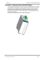
Appendix A: Restoring Factory Default Settings
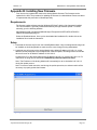
Appendix B: Installing New Firmware
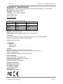
Appendix C: Specifications
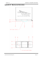
Appendix D: Mechanical Information
Xytronix Research & Design, Inc.
Page 3
Revision 1.3
DAQ Series™ Analog Module Users Manual
Trademark and Copyright Information
This document is Copyright ©2015 by Xytronix Research & Design, Inc. All rights reserved.
DAQ Series™ and ControlByWeb™ are Trademarks of Xytronix Research & Design, Inc. 2015.
All parts of this product and design including but not limited to firmware, hardware design,
schematics, PCB layout, concept, graphics, users manual, etc., are property of Xytronix Research
& Design, Inc. ©2015. Analog Module may not be opened, disassembled, copied, or reverseengineered.
No part of this manual may be reproduced or transmitted in any form or by any means, electronic
or mechanical, including photocopying or scanning, for any purpose other than the personal use
by the purchaser of this product. Xytronix Research & Design, Inc., assumes no responsibility for
any errors that may appear in this document.
Whereas effort has been made to make the information in this document as useful and accurate
as possible, Xytronix Research & Design, Inc. assumes no responsibility for the application,
usefulness, or completeness of the information contained herein. Under no circumstance will
Xytronix Research & Design, Inc. be responsible or liable for any damages or losses including
direct, indirect, special, incidental, or consequential damages or losses arising from either the use
of any information contained within this manual or the use of any products or services referenced
in this manual.
Xytronix Research & Design, Inc. reserves the right to change any product’s features,
specifications, documentation, warranties, fee schedules, and conditions at any time and without
notice.
Xytronix Research & Design, Inc.
Page 4
Revision 1.3
DAQ Series™ Analog Module Users Manual
Warranty
This Xytronix Research & Design, Inc. product has a warranty against defects in material and
workmanship for a period of one year from the date of shipment. During the warranty period,
Xytronix Research & Design, Inc. will, at its option, either repair or replace products that prove to
be defective. This warranty is extended to the original purchaser of the equipment only.
For warranty service or repair, the product must be properly packaged, and returned to Xytronix
Research & Design, Inc. The purchaser shall prepay all charges for shipping to Xytronix Research
& Design, Inc., and Xytronix Research & Design, Inc. will pay the shipping charges to return the
product to the purchaser as long as the product is shipped within the United States. If the product
is shipped outside of the United States, the purchaser shall pay all shipping charges, duties, and
taxes.
Limitation
The foregoing warranty shall not apply to defects or damage resulting from improper use or
misuse, unauthorized repair, tampering, modification, improper connection, or operation outside
the electrical/environmental specifications for the product. Further, the warranty does not cover
Acts of God, such as fire, flood, hurricanes, and tornadoes. This warranty does not cover damage
to property, equipment, direct, indirect, consequential, or incidental damage (including damage for
loss of business profit, business interruption, loss of data, and the like) arising out of the use or
misuse of this product.
UNDER NO CIRCUMSTANCES WILL THE LIABILITY OF XYTRONIX RESEARCH & DESIGN,
INC. TO THE PURCHASER OR ANY OTHER PARTY EXCEED THE ORIGINAL PURCHASE
PRICE OF THE PRODUCT, REGARDLESS OF THE FORM OF THE CLAIM. No other warranty
is expressed or implied. Xytronix Research & Design, Inc. specifically disclaims the implied
warranties or merchantability and fitness for a particular purpose. Some jurisdictions may not
allow the exclusion of limitation of liability for consequential or incidental damage.
Xytronix Research & Design, Inc.
Page 5
Revision 1.3
DAQ Series™ Analog Module Users Manual
FCC Statement
This device complies with Part 15 of the FCC Rules. Operation is subject to the following two
conditions:
‒
‒
This device may not cause harmful interference.
This device must accept any interference received, including interference that may
cause undesired operation.
Warning:
This equipment has been tested and found to comply with the limits for a Class B (Class A for POE
models) digital device, pursuant to Part 15 of the FCC Rules. These limits are designed to provide
reasonable protection. This equipment generates, uses and can radiate radio frequency energy
and, if not installed and used in accordance with the instructions, may cause interference to radio
communications. However, there is no guarantee that interference will not occur in a particular
installation. If this equipment does cause harmful interference to radio or television reception,
which can be determined by turning the equipment off and on, the user is encouraged to try to
correct the interference by one or more of the following measures:
‒
‒
‒
‒
Reorient or relocate the receiving antenna.
Increase the separation between the equipment and receiver.
Connect the equipment into an outlet on a circuit different from that to which the receiver
is connected.
Consult the dealer or an experienced radio/TV technician for help.
Notice:
Changes or modification not expressly approved by the party responsible for compliance could
void the user’s authority to operate the equipment.
Xytronix Research & Design, Inc.
Page 6
Revision 1.3
DAQ Series™ Analog Module Users Manual
Installation Guidelines (Read Before Installing)
Do not open the Analog Module enclosure. This will void the warranty.
‒
‒
‒
This unit must be installed by qualified personnel.
This unit must not be installed directly outdoors.
This unit must not be used for medical, life saving purposes, or for any purpose where its
failure could cause serious injury or the loss of life.
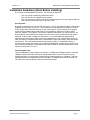
Security Notes
By design, the DAQ Series™ product are very secure. They do not support terminal or file transfer
programs such as telnet, ftp, ssh, etc. This means that it is not possible for someone to ‘break in’
to this module and access other devices on your local network. These products do not support
remote firmware updates which means that it is not possible for someone to remotely install
malicious software. The simplicity of this series of products make them very secure devices. As
with any device to be installed on a network, there are some security precautions that should be
observed. If this module is installed on the Internet, it is recommended that passwords be
enabled for the control page. Make sure secure passwords are used. Passwords should be at
least 8 characters in length and should be a combination of upper case letters, lower case letters,
and numbers. Don’t use passwords that would be easy to guess. For additional security, a
firewall may be used to limit access only to selected IP addresses. Another option may be to set
up a Virtual Private Network (VPN) between the network where the module resides and the client
machine (web browser, PLC, etc.).
Final installation note
This ControlByWeb™ product supports connection to 10Mbps and 100Mbps networks. Although
100Mbps networks are faster, the amount of data transferred to and from this device is very
minimal and little if any performance increase will be gained by setting it to 100Mbps. There are
advantages however, to operate this device at 10Mbps. At 10Mbps, less power is required, the
unit runs cooler, and the lifetime of the product will be extended.
Xytronix Research & Design, Inc.
Page 7
Revision 1.3
DAQ Series™ Analog Module Users Manual
Section 1: Introduction
The DAQ Series™ Analog Module is an industrial grade, Ethernet data acquisition module with
eight analog inputs. It can be configured and monitored over standard networks including private
networks, IP-based industrial control networks, and the Internet. Users can view the value of the
analog inputs using a web browser or a custom application. Computers, PLCs, or automation
controllers may monitor input values by sending text commands over the network and reading
XML status pages from the module, or by using Modbus/TCP protocol. Up to four other
ControlByWeb™ products can be controlled by the Analog Module as the analog inputs change
state.
The Analog Module is very easy to set up using a web browser. It has a simple “Control Page”,
which displays the analog readings of the module. The Analog Module can be setup to accept
either eight single-ended analog signals, four differential analog signals, or a combination of
singled ended and differential inputs. For example, inputs 0 and 1 could be setup to accept a
differential signal and the other 6 inputs could be setup to accept single ended signals.
1.1 Features
The Analog Module is very simple but has many features. Some features include:
‐ Eight analog input channels (can be configured as eight single ended inputs, four differential
inputs, or a combination of single ended and differential inputs).
‐ 10µV resolution.
‐ High input impedance.
‐ Full 0 to 5V Input Range (Input range can be changed with external resistors at inputs).
‐ 4-20mA Inputs (with external 250 ohm resistors.)
‐ No programming required.
‐ Easy to use as a stand alone device or as part of a large control system.
‐ Built-in web server provides simple, web based configuration and control.
‐ Control page can be customized with appropriate text and buttons.
‐ 10/100 Ethernet connectivity.
‐ Removable terminal connectors (included) simplifies wiring and service.
‐ Set high/low alarms for analog inputs which can send out alert emails and control remote
ControlByWeb™ devices.
‐ Apply a different slope and offset to each raw voltage reading.
‐ Custom applications can control the module with simple text commands and read XML
formatted status.
‐ Modbus/TCP protocol support provides inter-interoperability with devices/software from other
manufacturers.
‐ Password protection.
‐ Selectable TCP ports.
Xytronix Research & Design, Inc.
Page 8
Revision 1.3
DAQ Series™ Analog Module Users Manual
1.2 Available Models
The Analog Module is currently available in two models. The only difference between the two
models are the power supply requirements.
Part Number
Power Supply Requirements
X-DAQ-8A5-I
9-28VDC
Xytronix Research & Design, Inc.
Page 9
Revision 1.3
DAQ Series™ Analog Module Users Manual
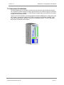
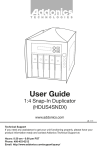
1.3 Connectors & Indicators
The Analog Module has a removable 12-position terminal connector and an Ethernet connector.
The 12-position terminal connector is used to provide power to the module as well as connections
for eight analog inputs. In addition, a 5 VDC reference voltage output is provided as a convenient
voltage source for analog sensors.
There are three LED indicators on the Analog Module labeled POWER (green), LINK (green), and
ACT (amber). Note that the LINK and ACT LEDs are located on the Ethernet connector. LINK
means the Analog Module is properly connected to an Ethernet network. The ACT LED flashes
when activity is detected on the network.
Xytronix Research & Design, Inc.
Page 10
Revision 1.3
DAQ Series™ Analog Module Users Manual
1.4 Example Configurations and Applications
The Analog Module is very versatile and can be used in many applications. Several basic
installation schemes are illustrated in this section.
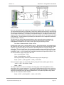
1.4.1 Monitoring Height, Position, Etc.
The illustration below shows a simple example of using the Analog Module with a potentiometer
based sensor commonly used to measure position, height, etc.
P o t e n t io m e t e r T y p e
S ensor
V in +
V in -
P o w e r S u p p ly
(6 V D C o r 9 -2 8 V D C )
+5V
AG N D
A0
IP
N e tw o rk
Potentiometer based sensors have three connections: power, ground, and output. Typically, the
+5V reference from the Analog Module, and the Agnd are used for power and ground (note that
the 5V reference is a very low power output so make sure sensor(s) don't draw more than the
rated current output). The output connection can be connected to any of the eight analog inputs on
the input module. This input can then be monitored through the Analog Module's control page.
1.4.2 Monitoring Temperature and Using 4-20mA Sensors
The illustration below shows an example of using the Analog Module to monitor temperature. The
example illustrates both measuring temperature and using 4-20mA sensors with the Analog
Module.
There are many different types of sensors that can be used to measure temperature. Most of
these sensors, such as the thermocouple in this example, provide an output signal that is
nonlinear. In order for the Analog Module to be used with a sensor that outputs a nonlinear signal,
the signal must be converted to a linear signal. Many devices exist that will convert a nonlinear
signal to a linear voltage or current. In this example a temperature transmitter is used to convert
the signal from a thermocouple to a linear 4-20mA current. The temperature transmitter outputs a
current that changes as the temperature changes.
The Analog Module has an input range of 0-5VDC. Since the output from the temperature
transmitter is a 4-20mA current, a resistor is used to convert the signal to a voltage at the input of
the Analog Module. A 250 Ohm resistor is the proper value for any sensor that outputs 4-20mA.
Xytronix Research & Design, Inc.
Page 11
Revision 1.3
DAQ Series™ Analog Module Users Manual
Once the Analog Module and supporting components are properly wired, they must be configured.
The temperature transmitter is configured for the specific characteristics and type of thermocouple.
The user may specify the expected temperature range that the thermocouple will be used, and the
current output for that range. For example, if the expected range is -160 degrees Celsius to 400
degrees Celsius, the temperature transmitter may be set to output 4mA at -160 degrees and 20mA
at 400 degrees. The documentation provided by the manufacturer of the temperature transmitter
should be used for this step.
The final step is to configure the Analog Module so that it reports the proper temperature by
assigning a slope and offset value for the input which the thermocouple is connected. The
Analog Module calculates the final value for each input using the following formula.
Final Value = Measured Value * Slope + Offset
By default the slope is set to 1 and the offset is set to 0. Using these settings, the Analog Module
will display the raw input value (0-5volts) on its control page (as well as the xml page and modbus
registers). By properly setting the slop and offset, the Analog Module will properly display the
temperature. The slope in this case, is the change in temperature that causes the Input 0 voltage
to change by 1 volt. To determine the slope, first determine the maximum voltage range that will
be applied to Input 0. In this example the temperature transmitter will output 4mA to 20mA. This
can be converted to voltage using Ohms law V=IR.
Vmin = 4mA*250ohms = 1VDC
Vmax = 20mA*250ohms = 5 VDC
Now to get the slope, divide the temperature range by the voltage range.
Slope = (400°C - (-160°C))/(5VDC – 1VDC) = 140°C/VDC
Once you have the slope, you can find the offset by using the linear equation (given above).
-160°C = 1VDC * 140°C/VDC + Offset
Offset = -300°C
The slope and offset can now be entered into the setup pages of the Analog Module so that
temperature will be properly displayed. The example illustrated determining the slope and offset
for displaying temperature in Celsius. To display the temperature in Fahrenheit, a new slope and
offset can be calculated using the steps presented above, except the temperature range will be
-256°F to 752°F instead of -160°F to 400°F.
Slope = (752°F - (-256°F))/(5VDC – 1VDC) = 252°F/VDC
Xytronix Research & Design, Inc.
Page 12
Revision 1.3
DAQ Series™ Analog Module Users Manual
-256°F = 1VDC * 252°F/VDC + Offset
Offset = -508°F
1.4.3 Monitoring Current
The illustration below shows an example of using the Analog Module in conjunction with a current
sensor to measure current draw of a motor.
P o w e r S u p p ly
(6 V D C o r 9 -2 8 V D C )
M o t o r P o w e r S u p p ly
V in +
V in AG N D
A0
0 -2 0 A m p s A C
to
0 -5 V D C
C u rre n t T ra n s d u c e r
IP
N e tw o rk
This example uses a self-powered current sensor that will measure current up to 20 Amps AC.
The sensor chosen produces a linear output with a range of 0-5VDC so it can be connected
directly to the input of the Analog Module. Note that the Analog Module has a high input
impedance so self-powered sensors will work properly when connected to its inputs. The
illustration shows how the sensor is connected. The slope should be calculated and entered into
the setup pages of the Analog Module. The slope calculation is given below.
Slope = (20 Amps – 0Amps)/(5 VDC – 0VDC) = 4 Amps/VDC
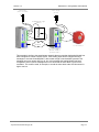
1.4.4 Control Application
The illustration below shows a simple example of using the Analog Module in conjunction with a
remote device to sound an alarm.
Xytronix Research & Design, Inc.
Page 13
Revision 1.3
DAQ Series™ Analog Module Users Manual
P o w e r S u p p ly
(6 V D C o r 9 -2 8 V D C )
P o w e r S u p p ly
(2 4 V D C )
P o te n tio m e t e r T y p e
S ensor
V in +
V in +
V in +5V
V in -
AG N D
G N D
1C
1N O
A0
+V
IP
N e tw o rk
2 4 V o lt A la r m B e ll
A n a lo g M o d u le
O t h e r C o n t r o lB y W e b
D e v ic e W ith R e la y s
( I n d u s t r ia l V e r s io n )
This example is similar to the potentiometer example above except that the Analog Module has
been configured to control a remote device. Each analog input can be configured to send
messages to a remote ControlByWeb™ device when a high or low threshold is passed. This
message can turn a remote relay on, off, etc. In this example the Analog Module has been
configured to send a remote message that in turn will sound an alarm when a given level is
exceeded. This could be used, for example, to sound an alarm when water level becomes too
high or too low.
Xytronix Research & Design, Inc.
Page 14
Revision 1.3
DAQ Series™ Analog Module Users Manual
Section 2: Installation and Setup
Installation consists of mounting the Analog Module, wiring analog inputs, connecting to an IP
network, providing power, and configuring via a web browser.
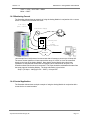
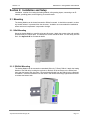
2.1 Mounting
The Analog Module can be be wall mounted or DIN rail mounted. It should be mounted in a clean
dry location where it is protected from the elements. Ventilation is recommended for installations
where ambient air temperature is expected to be high.
2.1.1 Wall Mounting
Mount the Analog Module to a wall by using two #8 screws. Attach the screws to the wall vertically
spaced exactly 2.5 inches apart. The head of the screws should be about 1/10 inch away from the
wall. See Appendix D for mechanical details.
2.1.2 DIN-Rail Mounting
The Analog Module can be mounted to a standard (35mm by 7.55mm) DIN rail. Attach the Analog
Module to the DIN rail by hooking the top hook on the back of the enclosure to the DIN rail and
then snap the bottom hook into place. Remove Analog Module from the DIN rail using a flat-head
screwdriver. Insert the screwdriver into the notch in the release tab and pry against the enclosure
to release the bottom hook.
Xytronix Research & Design, Inc.
Page 15
Revision 1.3
DAQ Series™ Analog Module Users Manual
2.2 Connection
CAUTION: MAKE SURE POWER IS SHUT OFF BEFORE WIRING!
A removable 12-terminal connector is provided for simple wiring to the Analog Module. The correct
wiring procedure is as follows;
1. Make sure power is turned off.
2. Remove terminal connectors from the Analog Module and make wiring connections to the
terminals.
3. Reconnect terminal connectors.
4. Apply power.
IMPORTANT: MAKE SURE WIRES ARE PROPERLY ATTACHED TO THE TERMINALS AND
THAT THE TERMINALS ARE TIGHT!
B a d C o n n e c to r E x a m p le .
S t ra n d (s ) o f w ire a re lo o s e
W ire s a re s t rip p e d t o o f a r b a c k
G o o d C o n n e c to r E x a m p le .
W ire s a r e s t r ip p e d c o r re c t
a m o u n t a n d t h e re a re n o lo o s e
s tra n d s th a t c a n c a u s e s h o rts
Xytronix Research & Design, Inc.
Page 16
Revision 1.3
DAQ Series™ Analog Module Users Manual
12-Pin Connector Pinout
Pin
Description
VIn+
Power supply input +. Connect to the positive side of
the
appropriate power supply. DO NOT EXCEED
MAXIMUM
POWER SUPPLY VOLTAGE.
Model X-DAQ-8A5-6
6VDC Power Supply
Model X-DAQ-8A5-I
9-28VDC Power supply
Vin+5V Ref
AGnd
Vin- Negative power supply input (Ground).
+5VDC Reference Output
Common ground for analog inputs in single-ended mode
A7
Analog input 7+ (single ended mode) or
Analog input 3- (differential mode)
A6
Analog input 6+ (single ended mode) or
Analog input 3+ (differential mode)
A5
Analog input 5+ (single ended mode) or
Analog input 2- (differential mode)
A4
Analog input 4+ (single ended mode) or
Analog input 2+ (differential mode)
A3
Analog input 3+ (single ended mode) or
Analog input 1- (differential mode)
A2
Analog input 2+ (single ended mode) or
Analog input 1+ (differential mode)
A1
Analog input 1+ (single ended mode) or
Analog input 0- (differential mode)
A0
Analog input 0+ (single ended mode) or
Analog input 0+ (differential mode)
2.2.1 Power Supply Connection
The Analog Module requires power for its internal logic circuits. Connect appropriate power supply
to the Vin+ and Vin- terminals.
Multiple Analog Modules may be connected to a single power supply by connecting the power
supply input terminals in parallel. The power supply must have a high enough current rating to
power all units connected (see specifications for current requirements for a specific model
number).
2.2.2 Network Connection
Connect the Ethernet port to a 10 Base T or 10/100 Base T Ethernet connection. This typically
connects to an Ethernet hub, switch, or router. For configuration, the Analog Module may be
connected directly to the Ethernet port on a computer using a “crossover” cable. Otherwise, for
connection through a hub or router, a standard “straight-thru” cable should be used.
Xytronix Research & Design, Inc.
Page 17
Revision 1.3
DAQ Series™ Analog Module Users Manual
2.2.3 Analog Input Connections
The analog inputs must be in the range of 0.0V to 5.0V. Analog sensors that provide an output
voltage in the range of 0 to 5 volts can be connected directly to the Analog Module. Voltages
outside this range will be clamped internally by the Analog Module to 0.0 and 5.0V respectively.
The inputs are internally protected with a 1K ohm resistor and a pair of over-voltage steering
diodes.
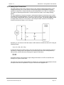
For some applications it may be necessary to add external resistors to scale the input to a value
compatible with the Analog Module. In the case of a sensor whose output levels are higher than 5
volts, a simple voltage divider can be used to scale down the output. The following diagram shows
a voltage divider circuit for a 0-10V sensor. In the example resister values for R1 and R2 are
chosen so that Vout will have a 0 to 5 volt range.
Generally, you can choose a 10K Ohm resistor for R2 and then calculate the value of R1 using the
following formula.
Vout = Vin * (R2 / (R1 + R2))
To determine the proper resister value to use in the example above, use the maximum output of
the sensor (10 VDC) as Vin in the equation, the maximum input value of the Analog Module (5
VDC) as Vout, and R2=10K Ohms. Solving for R1 gives R1=10K ohms.
R1=10K
R2=10K
As another example, if the maximum output voltage of the sensor is 15VDC, choose R2=10K.
Solving for R1 gives R1=20K ohms.
The input bias current of the Analog Module is relatively low, such that the Analog Module will work
with input circuits with an impedance of up up to 10K ohms with negligible error.
Xytronix Research & Design, Inc.
Page 18
Revision 1.3
DAQ Series™ Analog Module Users Manual
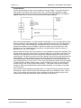
Current Sensors
Some senors generate an output current instead of an output voltage. To use these sensors, a
load resistor is connected in the current sensor loop. The load resistor generates a voltage
proportional to the sensor current which is in turn sensed by the Analog Module. The following
diagram shows how to connect a 4 to 20mA sensor to the Analog Module.
With a 250-ohm load resistor, a 4 to 20mA sensor will generate a 1.0 to 5.0V output which can be
directly connected to the Analog Module. A voltage measurement of less than 1.0V indicates the
current loop is open or that something is wrong with the sensor. Ensure the resistor wattage is
appropriate to handle the power dissipation. A 250-ohm resistor with 20mA flowing thru it will
generate 0.1W. The measurement accuracy will be no better than the resistor's accuracy. In
general use a 1% or a 0.1% resistor.
When making connections with current sensors it is very important to consider the lead dress. The
example above shows the voltage sense connections made with a 4-wire Kelvin connection. This
technique uses separate pairs of current-carrying and voltage-sensing wires to make accurate
measurements. The goal is to prevent current from flowing in the sense wires and terminals of the
Analog Module. If current is allowed to flow in the Agnd connections of the Analog Module, the
current will generate a small offset voltage due to the resistance of the wires and terminals. The
offset voltage becomes a source of error. This is especially problematic where the Analog Module
is used to measure multiple 4-20mA sensors. When connecting more than one 4-20ma sensor
consider using a “star” or single point ground topology. If the output current from one sensor
changes or affects the measurements of other sensors (crosstalk), you will need to re-consider
your connections.
Loop powered current transmitters normally require 7 to 8 Volts across their terminals in order to
work properly. With a 250-ohm resistor the load resistor will drop an additional 5-Volts. Allow 2volts or so for voltage drops across the wiring, especially if the wires are small or long. In this
example make certain your loop power source is at least 15-Volts (8+5+2).
Xytronix Research & Design, Inc.
Page 19
Revision 1.3
DAQ Series™ Analog Module Users Manual
Differential Inputs
The differential input mode can be used with sensors that have two analog outputs that are
referenced to each other instead of ground. When making differential voltage measurements, the
Analog Module is programmed to use a pair of inputs (2) to make a single differential
measurement. With differential inputs you must make certain both inputs are within the common
mode range (0-5V) of the input amplifiers. Normally this means you must provide some sort of
input bias. If no input bias is provided, even though the differential voltage is correct the absolute
voltages may drift into or beyond the 0-5V power rails of the amplifiers and will produce erratic
measurements.
The illustration below shows the connections for a Wheatstone bridge sensor with two output
signals. The outputs are connected to Ain1 and Ain2. The Analog Module must be programmed
for differential mode on “Ain1”. The analog measurement will be made by the voltage difference
between the two inputs (Ain1-Ain2). For differential measurements the measurement range is
±5V. For example, if Ain1 is 2.0V and Ain2 is 3.0V, the differential measurement will be -1.0V.
Note however, the absolute voltage of both inputs must be in the range of 0-5V for the input
amplifiers to work. For example:
Ain1
Ain2
Measurement
+5V
0V
+5.0V
0V
+5V
-5.0V
In the illustration below the bridge is excited (driven) by the 5.0V reference output. Notice also that
the bridge provides the necessary input bias.
The low input bias and high resolution inputs of the Analog Module together with the reference
output make the Analog Module workable with many bridge sensors without using a preamplifier or
other circuitry.
Xytronix Research & Design, Inc.
Page 20
Revision 1.3
DAQ Series™ Analog Module Users Manual
2.3 Establishing Communications for Setup
The Analog Module is set up using a web browser. The first task is to establish communications
between a computer and the Analog Module so that the browser-based configuration can begin.
To do this, the computer and the Analog Module must be physically connected to the same
network and both must have IP addresses on the same network. There are two ways to set up the
computer and the Analog Module so that they are on the same network. The first way (Option 1),
is to change the IP address of the Analog Module to an address that is on the same network as the
computer. The second way (Option 2) is to change the IP address of the computer to an address
that is on the same network that the Analog Module is set to by default.
2.3.1 Option 1: Assign a temporary IP address to the Analog Module
This option is used to TEMPORARILY assign an IP address to the Analog Module without the
need to change the IP address of the configuration computer. Note that the Analog Module will
only use this IP address as long as power is maintained. Once power is lost and restored, the
analog module will use the IP address assigned in the setup page and not the temporary address
assigned here. This means that once communications are established, the desired IP address
should be entered into the network setup page using the browser.
To assign the temporary IP address...
1.
Make sure the Analog Module and the configuration computer are connected to the same
physical network. This will not work through routers or gateways.
2.
Assign the address as follows...
Windows:
Open a Command Prompt (on Windows XP, select START, then RUN, then type “cmd”).
Type...
arp -s {new IP address} {serial number of analog module }
Note: IP address format is: xxx.xxx.xxx.xxx
Serial number format is: ss-ss-ss-ss-ss-ss
For example, to set an analog module (with serial number 00-0C-C8-01-00-01 ) to
10.10.10.40 the following command would be used.
arp -s 10.10.10.40 00-0c-c8-01-00-01
Next, type...
ping -l 102 {new IP address}
For example, if the new IP address is 10.10.10.40, the following command would be
used.
ping -l 102 10.10.10.40
Linux/Unix:
Open a terminal, change to root user (su -, then enter root password).
Type...
arp -s {new IP address} {serial number of analog module}
Note: IP address format is: xxx.xxx.xxx.xxx
Serial number format is: ss:ss:ss:ss:ss:ss
For example, to set an Analog Module (with serial number 00-0C-C8-01-00-01 ) to
Xytronix Research & Design, Inc.
Page 21
Revision 1.3
DAQ Series™ Analog Module Users Manual
10.10.10.40 the following command would be used.
arp -s 10.10.10.40 00:0c:c8:01:00:01
Next, type...
ping -s 102 {new IP address}
For example, if the new IP address is 10.10.10.40, the following command would be
used.
ping -s 102 10.10.10.40
Mac OS X
Open a terminal,
Note that the terminal is in the “Utilities” directory which is in “Applications” directory.
type
sudo arp -s {new IP address} {serial number of Analog Module}
Note: Administrator password is required.
IP address format is: xxx.xxx.xxx.xxx
Serial number format is: ss:ss:ss:ss:ss:ss
For example, to set an Analog Module (with serial number 00-0C-C8-01-00-01 ) to
10.10.10.40 the following command would be used.
sudo arp -s 10.10.10.40 00:0c:c8:01:00:01
Next, type...
ping -s 102 {new IP address}
For example, if the new IP address is 10.10.10.40, the following command would be
used.
ping -s 102 10.10.10.40
2.3.2 Option 2: Assign a temporary IP address to configuration computer
If the first option above is not used, you can use this option to communicate with the analog
module . By default, the Analog Module comes from the factory with an IP address of 192.168.1.2.
Communications with Analog Module may be established by assigning an IP address to the
configuration computer that is on the same network as the analog module(for example, the
configuration computer could be assigned to 192.168.1.5) .
Instructions for changing the IP address of the computer that will be used for the Analog Module
configuration are given here. Note that these instructions are specifically for computers with the
Windows XP operating system. For setup using other operating systems, refer to the appropriate
users manual.
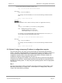
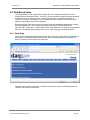
Step 1
Open the control panel by clicking on the start menu and then clicking on Control Panel. (Note
that control panel shown is in “Classic View”. If control panel is in “Category View” select the
“Classic View” option before proceeding.)
Xytronix Research & Design, Inc.
Page 22
Revision 1.3
DAQ Series™ Analog Module Users Manual
Step 2
Double click on the icon labeled Network Connections. The following menu will pop up.
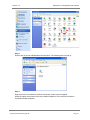
Step 3
Right click on the icon labeled Local Area Connection. Another menu will appear.
Select the option at the bottom of the menu labeled Properties. The Local Area Connection
Properties window will appear.
Xytronix Research & Design, Inc.
Page 23
Revision 1.3
DAQ Series™ Analog Module Users Manual
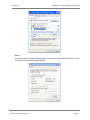
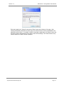
Step 4
On the Local Area Connection Properties page scroll down to Internet Protocol (TCP/IPv4), select
it, and then click the button labeled properties.
Xytronix Research & Design, Inc.
Page 24
Revision 1.3
DAQ Series™ Analog Module Users Manual
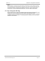
Step 5
Before making any changes to the network settings, write down the current settings so that they
can be restored once the Analog Module is configured. Next, select the radio button labeled “Use
the following IP address,” and type in the IP address 192.168.1.50. Type in a subnet mask of
255.255.255.0. Leave the default gateway field blank. Click OK to apply the new settings.
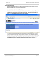
2.3.3 Open Configuration Web Page
Once the network is set up, open the configuration setup page by typing the following URL into the
browser: http://192.168.1.2/setup.html (note that if option 1 above was used for initial
configuration, replace the IP address given here with the newly assigned IP address). A password
is required to change any parameters. The default password is ‘webrelay’ (do not include quotes,
password is case sensitive).
Xytronix Research & Design, Inc.
Page 25
Revision 1.3
DAQ Series™ Analog Module Users Manual
2.4 Web-Based Setup
The Analog Module is fully configurable through HTML 4.0 compliant web browsers such as
Internet Explorer and Mozilla Firefox. It’s easy to use tab based menu system has been designed
to allow the unit to be configured easily. Note that in this chapter, the default IP address of
192.168.1.2 is used in all examples. If the IP address has been changed, substitute the new IP
address for the address shown in the examples.
Before proceeding, make sure a network connection has been established between the computer
and the Analog Module. This is done by typing the following URL into the web browser:
http://192.168.1.2/setup.html. Another way to check communications is to ping the Analog Module
(from the command prompt (type ping 192.168.1.2)). Each setup page is described below.
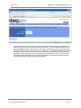
2.4.1 Setup Page
This is the initial page that appears when the URL http://192.168.1.2/setup.html is entered into the
web browser. It provides basic information about the unit. Navigating between setup pages is
done by clicking on the tabs at the top of the page.
The setup pages require a password. The default username is 'admin', the default password is
‘webrelay’ (no quotes, all lower case).
Xytronix Research & Design, Inc.
Page 26
Revision 1.3
DAQ Series™ Analog Module Users Manual
Each setup page has a “Submit” button and a “Reset” button at the bottom of the page. After
entering the desired parameters into each page, the “Submit” button must be pressed before any
parameters will be saved. If a mistake is made in entering the parameters, the “Reset” button may
be used to restore all parameters on the page to their current settings. The “Reset” button is only
effective before the “Submit” button is pressed.
Xytronix Research & Design, Inc.
Page 27
Revision 1.3
DAQ Series™ Analog Module Users Manual
2.4.2 Network Setup Page
The network parameters are changed on this page. Note that if multiple analog modules are used
on the same network, install one unit at a time and set the IP address of each unit before
connecting the next unit to the network. This avoids having multiple units installed on the network
with the same factory default IP address at the same time. It may be necessary to clear the arp
cache each time you swap Analog Modules on the network (this is because each unit has the
same default IP address but a different mac address). This is done by typing arp -d in the
command prompt of a Windows computer (arp -d -a as super user on Apple OSX). Also note
that the unit must be power-cycled (power disconnected, then reconnected) before network
settings take effect. No other setup page requires power-cycling for the settings to take effect.
IP Address
The Analog Module requires a static IP address. This is a unique address that identifies the
Analog Module on the network. Dynamic IP address assignment is not supported. The lack of
dynamic IP addressing support is intentional because dynamically changing the IP address
would make it difficult for a client to access the web server built into the Analog Module. The
IP address is specific to the network where the unit will be installed, and must be obtained
from the network administrator.
This guide is not meant to be a tutorial on IP addressing, however a few comments about IP
addressing are given here. If the Analog Module will be used over the Internet, the IP address
must be a routable address assigned by the upstream Internet Service Provider (ISP).
In cases where the ISP only provides a single routable IP address for the entire network (this
is typical with ISPs such as cable providers), a proxy server (or gateway router) may be used.
A proxy server allows multiple devices to connect to the Internet using a single routable IP
address. Many small routers from LinkSys, Dlink, and Netgear perform proxy server functions.
If a proxy server is used, the Analog Module will not be accessible from the Internet until the
proxy server is properly configured (forward proper port to the Analog Module). This
information is mentioned for convenience but details of setting up a configuration such as this
is beyond the scope of this manual.
Xytronix Research & Design, Inc.
Page 28
Revision 1.3
DAQ Series™ Analog Module Users Manual
If the Analog Module is used on a private network only and is NOT used over the Internet, a
routable IP address is not necessary. This may be the case when the analog module is used
to control a device in another room or a nearby building.
If the Analog Module will be installed on a simple, private network that does not connect to the
Internet, the default IP address may be used as long as no other device on the network uses
the same address. If multiple units are installed on the same network, each unit must have its
own unique IP address. For example, the Analog Module comes from the factory with a
default IP address of 192.168.1.2. If multiple units are used, change the IP address for each
unit (192.168.1.3, 192.168.1.4, 192.168.1.5 etc.).
Netmask
This specifies the size of the local network. This must be obtained from the network
administrator. By default, the netmask is set to 255.255.255.0.
Broadcast
This specifies the broadcast address. This must be obtained from the network administrator.
By default, this is set to 192.168.1.255.
Gateway
This specifies the IP address of the gateway router. This must be obtained from the network
administrator. By default, this is set to 192.168.1.1.
TCP Port
This specifies the TCP port used for communications with the Analog Module. By default, the
port is set to 80 which is the standard http port. It is recommended that the port not be
changed without an understanding of TCP/IP and ports.
Changing the port can be useful for accessing multiple Analog Modules which are installed
behind a gateway router on a private network that uses non-routable IP addresses
(192.168.x.x, 10.x.x.x, and 172.16.x.x through 172.31.x.x are non-routable or private IP
addresses). In this case, each Analog Module would be assigned a different port (for example
8000, 8001, 8002, etc). The gateway router would be set up to forward all traffic for each of
the assigned ports to the IP address of the Analog Module which uses that port. The Analog
Modules could then be accessed from outside the private network by entering the IP address
of the gateway and the port for the desired Analog Module. Note that whenever any port is
assigned other than port 80, all communications with that Analog Module must include the
port. For example, if the Analog Module is assigned port 8000, access to the setup pages
would require the following URL to be entered; http://192.168.1.2:8000/setup.html.
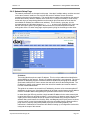
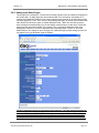
An example screen shot of a gateway router configuration is given below. This setup allows
seven ControlByWeb™ products to be accessed on a private network behind a gateway
router. Note that this screen shot is simply an example of a typical router setup page. Routers
will vary.
Xytronix Research & Design, Inc.
Page 29
Revision 1.3
DAQ Series™ Analog Module Users Manual
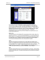
In the example, the seven ControlByWeb™ products are assigned IP addresses of
10.10.10.41 to 10.10.10.47. The first device labeled WebRelay 1 has an IP address of
10.10.10.41 and is assigned port 8001. Note that in the WebRelay™ setup page (under
Network settings tab), TCP Port 8001 must be specified for this device. The second device,
labeled WebRelay 2 has an IP address of 10.10.10.42 and is assigned port 8002. This
WebRelay™ must have its TCP Port set to 8002 in it's network settings page. This pattern
continues through 10.10.10.77 which is assigned the port 8007. To access the
ControlByWeb™ units from the Internet, enter the IP address of the gateway plus the port
number of the desired device.
Modbus Port:
This specifies the port used for Modbus/TCP communications with the analog module. By
default this is set to port 502 which is the standard Modbus port. For users not familiar with
Modbus, Modbus is a messaging structure protocol used in industrial manufacturing control
and automation. It is an open protocol and offers interoperability with software and devices
from other manufacturers. If Modbus is not used, this setting can be ignored. Modbus
communications are disabled whenever the control password is enabled.
Speed
This option sets the data rate of the Ethernet port. Both 10Mbps and 100Mbps can be
selected. The 100Mbps option offers faster communications but the amount of data to and
from the Analog Module is so small that users will not likely notice much of a difference. When
the Analog Module is set to 10Mbps, it draws less power and runs a little cooler which
translate into a longer product life. IT IS RECOMMENDED THAT THIS SETTING BE LEFT AT
10MBPS UNLESS THE USER HAS A SPECIFIC REASON TO USE 100MBPS.
Mode
This option allows the Ethernet port to be set to Half Duplex or Full Duplex. Legacy Ethernet
operates in Half Duplex mode which means that devices can either send data or receive data,
but not both at the same time. Full duplex means that devices can send and receive data at
the same time.
Xytronix Research & Design, Inc.
Page 30
Revision 1.3
DAQ Series™ Analog Module Users Manual
MTU Setting
To change the MTU, manually enter the advSetup.html (case sensitive) page into the address
bar. (http://192.168.1.2/advSetup.html). This new setup page will have a text box that will allow
the MTU to be changed. The valid range is 256 to 1476 bytes. MTU is a network parameter
that stands for Maximum Transmission Unit. This defines the max size, in bytes, of the TCP
packets sent out from the device. This normally can be left alone, but there are some
circumstances where it might be beneficial to change it. One of these circumstances is when
the device is to be used over a VPN (virtual private network). VPN's add extra information to
TCP packets, if the new packets are too big to physically travel across the network (greater
than about 1500 bytes) then the packets will be split up. This causes problems for some
firewalls and those firewalls will just discard the packets. To fix this, the MTU can be adjusted
until the TCP packets do not get split up.
2.4.3 Email Setup Page
The email setup page is used to configure the device for use with a SMTP server, as well as to
define up to three recipient email addresses. The settings on this page will be used when
inputs are configured to send email messages. If none of the inputs are configured to send
email messages then the settings on this page can be left at there default values.
DNS Address
If Email notification will be used, enter the IP address of a DNS server. This is used to lookup
the IP address of the mail server. If the IP address of the mail server is known, it can be
directly entered into this field. If this is the case, the Mail Server field should be left blank.
This will cause the Analog Module to attempt to send email messages directly to this IP
address, bypassing the need for a DNS server.
Xytronix Research & Design, Inc.
Page 31
Revision 1.3
DAQ Series™ Analog Module Users Manual
Mail Server (SMTP)
If email notification will be used, enter the name of an SMTP email server here. If this field is
left blank, the Analog Module will try and send email messages directly to the IP address
specified in the DNS Address field. This allows the DNS server to be bypassed if the IP
address of the SMTP server is already known.
Mail Server Port
This is the port which the SMTP server will be listening on for incoming messages. By default
most SMTP servers use port 25.
Domain
This is the domain name for the sender. This value usually follows the @ sign in the senders
email address. By default this is set to controlbyweb.com, and the return email address is
[email protected]
User Name (Optional)
If the SMTP server requires authentication, the Analog Module supports the AUTH LOGIN
method of authentication. With this method the user name and password entered on this page
are sent to the SMTP server in a Base64 encoded string. If the user name and password are
found to be valid for the SMTP server then the email will be delivered. If the user name and
password fields are left blank then an attempt to send the email will be made without any
authentication.
Password (Optional)
This field is used to specify the password used for authentication with an SMTP server. See
the explanation of the User Name field for more information.
Return Email
This is the email address that will show up in the From: line of the email. If there are problems
delivering the email, error messages will be sent to this email address. Also, recipients of
emails from this device can respond back to this email address.
Email 1 Address
If email notification will be used, enter the email address of the first recipient of notification
messages.
Email 2 Address
If email notification will be used and messages will be sent to at least two recipients, enter the
email address of the second recipient of email notification messages.
Email 3 Address
If email notification will be used and messages will be sent to three recipients, enter the email
address of the third recipient of email notification messages
Xytronix Research & Design, Inc.
Page 32
Revision 1.3
DAQ Series™ Analog Module Users Manual
2.4.4 Password Setup Page
The password setup page is used to change and enable passwords. A password is required for
the setup pages but is optional for the control page. The password is enabled or disabled for the
control page by using the Yes or No radio buttons. Enabling the control page password also
enables the requirement for a password when reading/writing XML pages. Enabling the control
page password also disables the ability to communicate with the Analog Module using Modbus.
Note that when the password is changed, the password may be displayed in the browser’s history
in clear text. It is advisable to clear the browsers history after setting the password. Passwords
may be alpha-numeric passwords up to 10 characters.
Xytronix Research & Design, Inc.
Page 33
Revision 1.3
DAQ Series™ Analog Module Users Manual
2.4.5 Analog Input Setup Pages
These pages (An 0 through An 7) define how the analog inputs function and what inputs appear on
the control page. All eight pages are almost identical with a few exceptions. Setup page An 0
includes some additional settings for the control page that aren't present on the other setup pages,
and setup pages An 0, An 2, An 4, and An 6 have settings that apply to remote communication with
other devices as well as the option to enable differential mode. When one of these inputs has
been configured as a differential input, the next higher numbered input is used as the -IN and the
settings for that input aren't editable. For example, if An 4 is placed in differential mode, then
analog input 4 will act as +IN for the differential pair, and analog input 5 will act as -IN for the
differential pair. The settings for An 4 will apply to the differential pair, and the settings for An 5 will
not appear as long as differential mode is enabled.
The first 3 parameters appear on the Analog 0 setup page only. The input parameters appear on
all the Analog input setup pages accept for the Differential Mode setting which appears on even
numbered input setup pages only. The final three parameters appear on even numbered input
setup pages and apply to that analog input as well as the odd numbered analog input directly
following. This is because each pair of analog inputs communicate with the same remote device.
Xytronix Research & Design, Inc.
Page 34
Revision 1.3
DAQ Series™ Analog Module Users Manual
Main Header Text
The text entered here appears at the top of the control page. It also appears in the header of
the email text when the email notification is used. This field can be up to 25 characters in
length.
Auto Refresh Page
Web pages traditionally display static information. The Analog Module control page, however,
displays information that is dynamic. Each time the control page is loaded to the browser, it
displays a snapshot of the current status of the unit. Whenever the state of a sensor changes,
the control page will be obsolete until the page is refreshed. The Analog Module cannot force
the web page to be updated when the sensors update. The 'Auto Refresh Page' option will
cause the control page to continually update its contents by setting a timer in the web page
that causes it to be reloaded at a specified time interval.
Duration
When the 'Auto Refresh Page' option is set to YES, this field specifies the time interval in
seconds that the page will be refreshed. It can be set from 1 to 32 seconds.
Differential Mode
This option determines whether or not two inputs will act together in differential mode or
whether they are independent of each other in single-ended mode. When in differential
mode, only one set of options for the first input will be displayed. These options will apply to
the differential pair while they are in the differential mode. When two inputs are in differential
mode, the first input acts as the positive input and the second input acts as the negative input.
When the inputs are in single-ended mode, each input individually acts as the positive input
while the common ground (pin 4) acts as the negative input.
Differential mode can be used with sensors that have two analog outputs that are referenced
to each other instead of ground.
Mode
Input
0
1
2
3
4
5
6
7
IN+
ININ+
ININ+
ININ+
SingleEnded
ININ+
ININ+
ININ+
ININ+
IN+
Differential
IN-
ININ+
ININ+
ININ+
Xytronix Research & Design, Inc.
AGnd
IN-
Page 35
Revision 1.3
DAQ Series™ Analog Module Users Manual
Input Description
The text in this field appears to the left of the analog reading associated with the input. This
text also appears in the email status messages when that feature is enabled. This field can be
up to 20 characters in length.
Units
The contents of this field will be displayed after the analog measurement in the control page,
XML page, and email messages. This field doesn't change the value in any way, it is simply
used to add units to the value shown. It can be up to 4 characters long. By default this field is
cleared.
Display Input Status
When this parameter is set to YES, the analog value will appear on the control page and in
emails. When this parameter is set to NO, the analog value for this input will not appear on
the control page or in email messages.
Slope
The analog inputs have an input range from 0-5VDC. In many cases, the inputs must be
scaled to represent “real-world” measurements that are outside the range of 0-5. The Analog
Module reads the “raw” value from each input, and calculates the number that represents the
“real-world” measurement that the user is actually interested in. This real-world value (referred
to as the “scaled” value in this section) is calculated using the following linear formula.
Scaled Analog Value = Slope*Raw Voltage + Offset
The scaled value is the only number that the the Analog Module keeps track of and uses. This
is the value which is used to determine alarm conditions and is the value that is displayed on
the control page, the XML page, and it is also returned when modbus values are read.
The “slope” in the formula above is provided by the user and is entered in this field. The
default value for this field is 1. When both the slope and offset are set to their default values,
the Scaled Value = the Raw Voltage.
Note: The slope and offset can be calculated by hand and entered directly into these fields, or
can be calculated automatically by the Analog Module through the calibration setup page
described in Section 2.5.6.
Offset:
See the description of slope and offset in the previous paragraph.
The “offset” in the formula above is provided by the user and is entered in this field. The
default value for this field is 0. When both the slope and offset are set to their default values,
the Scaled Value = the Raw Voltage.
Note: The slope and offset can be calculated by hand and entered directly into these fields, or
can be calculated automatically by the Analog Module through the calibration setup page
described in Section 2.5.6.
Message Options
Each input has the capability of sending out a variety of messages to a variety of destinations
based on the current analog reading of the input and the trigger and delta values. The
Message Options parameter defines the type of message is sent (email, on/off, analog value)
and where the message should be sent to (email server, other device defined by IP address).
The following options are available:
Xytronix Research & Design, Inc.
Page 36
Revision 1.3
DAQ Series™ Analog Module Users Manual
‐ Disabled- Don't send messages out for this input.
‐ Send email on triggers- When the scaled analog value moves above the upper
trigger or below the lower trigger, an email message will be sent to the email recipients
selected. If the scaled analog value falls back within the limits of the upper and lower
triggers, another email message will be sent to the same recipients to indicate the
scaled analog value has returned to its normal state. To avoid an excess of email
messages, the scaled analog value must move back into the normal range by the
amount specified in the 'delta' parameter. For example, suppose the upper trigger is
set to 25 and delta is set to 0.5. In this case, a high alarm will occur when the scaled
analog value rises above 25, and a normal alarm will occur when the measured value
returns below 24.5, which is the upper trigger minus the delta. The delta value can be
considered the dead band when email messages are to be sent out based on the
triggers.
‐ Send email when value changes by delta- When the scaled analog value changes
by the amount defined in the parameter 'delta', an email message will be sent to the
selected email recipient(s). When power is applied to the unit, the current value is
recorded and used as the initial reference (message will be sent immediately when
power is applied and this option is selected). When this option is first enabled in the
setup pages, the current value is recorded at that time and used as the initial
reference (message will be sent immediately when this option is selected).
‐ Send on/off message to remote unit on triggers- When the scaled analog value is
above the upper trigger or below the lower trigger, a command is sent to the remote
device at the IP address defined in the field 'Remote Unit IP Address' field to turn a
relay within that device on. When the scaled analog value returns to a value that falls
within the upper and lower triggers, a command is sent to the remote device to turn
the relay within that device off. To avoid an excess of commands being sent, the
'delta' parameter is used as a deadband region. When the scaled analog value rises
above the upper trigger or falls below the lower trigger, the message will be sent
immediately. When the scaled analog value moves back into normal range, it must
move into the normal range by the amount of the “delta”value before the message is
sent. For example, suppose the upper trigger is set to 25 and delta is set to 0.5. In
this case, a high alarm will occur when the scaled analog value rises above 25, and a
normal alarm will occur when the measured value returns below 24.5, which is the
upper trigger minus the delta.
‐ Send value to remote unit on triggers- When the scaled analog value is above the
upper trigger or below the lower trigger, the raw voltage measurement will be sent to
the remote device at the IP address defined in the field 'Remote Unit IP Address'.
When the scaled analog value of the input returns to a value that falls within the
normal range, the raw voltage reading will be sent to the remote device. To avoid an
excess of messages being sent, the 'delta' parameter is used as a deadband region.
When the scaled analog value rises above the upper trigger or falls below the lower
trigger, the message will be sent immediately. When the scaled analog value moves
back into normal range, it must move into the normal range by the amount of the
“delta”value before the message is sent. For example, suppose the upper trigger is
set to 25 and delta is set to 0.5. In this case, a high alarm will occur when the scaled
analog value rises above 25, and a normal alarm will occur when the measured value
returns below 24.5, which is the upper trigger minus the delta.
‐ Send value to remote unit on each change by delta- When the scaled analog value
changes by the amount defined in the 'delta' field, the raw voltage measurement will
be sent to the remote device at the IP address defined in the field 'Remote Unit IP
Address'. When power is applied to the unit, the current value of the value is recorded
and used as the initial reference (message will be sent at power-up when this option is
selected). When this option is first enabled in the setup pages, the current value is
recorded at that time and used as the initial reference (message will be sent
immediately when this option is enabled).
Xytronix Research & Design, Inc.
Page 37
Revision 1.3
DAQ Series™ Analog Module Users Manual
Use Email Address
When the input is set to send email messages, this field specifies which email address the
message will be sent to. There are three check boxes which specify which email address on
the Email Setup page will be used. When the input is set to send email messages, the
message can be sent to one, two, or all of the email addresses specified on the Email Setup
Page.
Upper Trigger
This option defines the upper alarm trigger. This value should be greater than the lower
trigger. When the scaled analog value moves from lower than this value to greater than or
equal to this value, the input is in a high alarm state. The actions taken as a result of this state
are determined by the 'Message Options' parameter. To effectively disable the upper trigger
while using the lower trigger, set this value to a very high number.
Lower Trigger
This option defines the lower alarm trigger. This value should be lower than the upper trigger.
When the scaled analog value moves from the greater than this value to less than or equal to
this value, the input will be in a low alarm state. The actions taken as a result of this state are
determined by the 'Message Options' parameter. To effectively disable the lower trigger while
using the upper trigger, set this value to a very low number.
Delta
This field is used to specify the delta value. The delta value is used in two ways. First, it is
used when the input is configured to send messages based upon a delta. In this case, the
when the scaled analog value changes by the amount specified in this field, a messages will
be sent. Secondly, when upper and/or lower triggers are used, the delta value is used as a
deadband that eliminates alarm state toggling quickly when the scaled analog value is close to
the trigger values. In this case, when the scaled analog value changes from a normal value to
a value that is above the upper trigger or lower than the lower trigger, the input is in an alarm
condition. The input will stay in the alarm condition until the scaled analog value moves back
into the normal range by a minimum of the delta value. For example, suppose the upper
trigger is set to 25 and delta is set to 0.5. In this case, a high alarm will occur when the scaled
analog value rises above 25, and a normal alarm will occur when the measured value returns
below 24.5, which is the upper trigger minus the delta. The delta value can be considered the
dead band when email messages are to be sent out based on the triggers.
Send Periodic Message
When this field is set to Yes, and the 'Message Option' parameter is set to send commands to
a remote device (not email), messages will be sent periodically to the remote device (even if
input value does not change). The type of message sent (on/off command or value) is
determined by which 'Message Option' is selected. The rate at which the periodic messages
are sent is determined by the parameter 'Period'.
Period
This field specifies the rate at which periodic message are sent to a remote device when the
'Send Periodic Message' field is set to Yes, and a 'Message Option' is selected that sends
messages to a remote unit. This field can be set within the range of 10 to 4223173 seconds
(roughly 48 days).
Xytronix Research & Design, Inc.
Page 38
Revision 1.3
DAQ Series™ Analog Module Users Manual
Remote Output #:
When the 'Message Option' field is set to send messages to a remote unit (not email
messages) the messages are sent to the remote device with this output number. For
example, if an on/off command is sent to a WebRelay-Quad™, this field specifies which if the
four relays will be affected. Note this when sending commands to a single WebRelay™, (with
only 1 relay) this filed should be set to 0.
Remote Unit IP Address
When an input is configured to send messages to a remote device, this field specifies IP
address of the remote device. Note that the Analog Module is capable of sending messages
to up to four devices Each IP address setting is shared between two analog inputs (An 0/1, An
2/3, An 4/5, An 6/7). Both inputs that share the IP address can send different messages to the
device, but they cannot send messages to different devices.
Remote Unit TCP Port
When an input is configured to send messages to a remote device, this field specifies TCP
port used on the the remote device. Like the IP Address setting, each TCP Port setting is
shared between two analog inputs (TCP Port settings are associated with the same analog
input pairs as IP address settings).
Remote Unit Password
When an input is configured to send messages to a remote device, this field specifies the
password used to access the device. This is necessary whenever password authentication is
enabled on the remote device.
Xytronix Research & Design, Inc.
Page 39
Revision 1.3
DAQ Series™ Analog Module Users Manual
2.5.6 Calibration Page
Each input value can be scaled so the analog readings represent real-world values. The Analog
Module scales the inputs using the linear equation below.
Scaled Value = Slope*Raw Voltage + Offset
By default, the slope is set to 1 and the offset is set to 0 which which will not scale the input. If the
input does need to be scaled, the slope and offset for sensors can be manually entered into the
analog setup pages. Alternatively, if the slope and offset information are not readily available, the
calibration page can be used to determine the slope and offset. This is done by connecting the
sensor to the Analog Module and performing a 2-point calibration.
The calibration process requires that precise measurements be known for two sensor positions
(usually on each end of the scale). Once the sensor is connected, move it to the first calibration
point and enter the sensor number (analog input number) and measurement value (scaled analog
value) into the calibration page. Press submit. Next, move the sensor to the second calibration
point, enter that value into the calibration page and press submit. Once these two points are
entered, the Analog Module automatically calculates the slope and offset for that sensor.
Xytronix Research & Design, Inc.
Page 40
Revision 1.3
DAQ Series™ Analog Module Users Manual
An example will be used to illustrate the use of the calibration page. Suppose a potentiometer
sensor is used with a float to measure water level of a river. The water level is measured in feet
and is reported as elevation (with respect to sea level). In this example, the river bed (no water)
measures 5237 feet and the river can move up to 5289 feet. The measurement float can move the
full range. Once the sensor is set up and connected to the Analog Module, the float should be
physically moved to the bottom of the river and the first measurement (5337) is entered into the
Calibrate page and submitted. Next, the float is physically moved to the high position and the
second measurement (5289) is entered and submitted.
Xytronix Research & Design, Inc.
Page 41
Revision 1.3
DAQ Series™ Analog Module Users Manual
Section 3: Operation
The Analog Module can be operated using a web browser, by sending text commands to an XML
status/control page, or by sending Modbus/TCP requests.
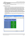
3.1 Browser Operation
Once the unit is set up, the control page may be accessed by typing the following URL into the
web browser: http://192.168.1.2 (Note that if the IP address was changed, replace the default IP
address shown with the new address that was assigned. Note also that if any port is used other
than port 80, the port must also be included in the request: http://192.168.1.2:8000 ) The new
control page will appear. The control page displays the final values (raw voltages with the slope
and offset applied) for each input at the time of the request. Note, only those inputs who have the
'Display Input Status' setting found on the input setup pages set to YES will be displayed on the
control page. A control page is shown below. In this example, all the inputs use the default
settings accept for input 3. Input three has been configured to convert the raw voltage value from
volts to an angle in degrees, 0 degrees corresponding to 0 volts and 360 degrees corresponding to
5 volts. Notice also that the 'Units' option from the input setup page is being used to display the
units next to the value.
Note: When the input signal is out of range, meaning it is less than 0 volts or greater than 5, then
the control page will indicate this by displaying the text OUT_OF_RANGE instead of a value for
the input.
Xytronix Research & Design, Inc.
Page 42
Revision 1.3
DAQ Series™ Analog Module Users Manual
3.2 XML Operation
Custom computer applications may be created to monitor and control the Analog Module without
using a web browser. There are two XML pages used for monitoring and controlling the unit.
Monitoring the analog readings is done by sending a request to port 80 (or port specified in setup)
for the XML page state.xml. Monitoring the analog input modes and resolution can be achieved by
requesting the XML page adcstate.xml. The use of these XML pages can be demonstrated by
entering commands into the URL line of a web browser.
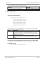
3.2.1 state.xml
Request the current state:
http://192.168.1.2/state.xml
This will return the following XML page.:
<?xml version="1.0" encoding="utf-8" ?>
<datavalues>
<input0state>2.50487</input0state>
<input1state>2.50494</input1state>
<input2state>2.50673</input2state>
<input3state>180.42037 deg.</input3state>
<input4state>2.50496</input4state>
<input5state>2.50494</input5state>
<input6state>2.50491</input6state>
<input7state>2.50491</input7state>
<powerupflag>1</powerupflag>
</datavalues>
The tags <inputstate> and <powerupflag> indicate the current state of the Analog Module. Values
for each tag are described below.
XML Tags*
Monitor Values
<inputXstate>
180.42037 Deg. = Scaled analog value from the corresponding Analog
Input.
OUT_OF_RANGE = Raw analog value lies outside the valid input rand of 0
to 5V
The powerup flag can be used to detect power loss. Whenever the unit is
powered on, the powerup flag will be set to 1. This flag can be cleared by the
user.
The only way the powerup flag can be set to 1 is if the unit looses power, and
is then powered on again after the flag has been cleared.
* 'X' is replaced by the Analog Input number.
<powerupflag>
When commands are sent to the Analog Module, its current state is returned in the form of an XML
page.
Note: The XML reply does not contain headers. To generate an XML reply with headers use the
following command:
Command
Description
stateFull.xml
Return the XML reply with headers
Xytronix Research & Design, Inc.
Page 43
Revision 1.3
DAQ Series™ Analog Module Users Manual
The XML commands can also be sent without having the Analog Module return the XML page.
This is accomplished by adding the noReply field as follows.
Command
Description
state.xml?relayState=1&noReply=1
Turn Relay ON without returning state.
state.xml?relayState=0&noReply=1
Turn Relay OFF without returning state.
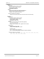
3.2.2 Mode and Resolution
Request the current mode of the analog inputs as well as current resolution:
http://192.168.1.2/adcstate.xml
This will return the following XML page.:
<?xml version="1.0" encoding="utf-8" ?>
<datavalues>
<resolution>24.6</resolution>
<an0_mode>single-ended</an0_mode>
<an1_mode>single-ended</an1_mode>
<an2_mode>single-ended</an2_mode>
<an3_mode>single-ended</an3_mode>
<an4_mode>single-ended</an4_mode>
<an5_mode>single-ended</an5_mode>
<an6_mode>single-ended</an6_mode>
<an7_mode>single-ended</an7_mode>
</datavalues>
The tags <resolution> and <anX_mode> indicate the current settings of the analog to digital
convert. Values for each tag are described below.
XML Tag*
Description
<resolution> This is the current resolution of the analog to digital converter. This resolution
is specified in bits and can be changed through the XML page. Higher
resolutions slow down the conversion process. The highest resolution is the
default resolution of 24.6 bits.
Single-ended (The input is being used in single-ended mode)
Differential (The input is being used in differential mode with the adjacent
input.)
* 'X' is replaced by the Analog Input number.
<anX_mode>
Commands can be sent to the Analog Module to change the resolution of the analog to digital
convert. This allows the Analog Module to be adjusted for precision or speed. The resolution
setting applies to all the analog inputs. The following is an example of how to set the resolution.
Set resolution to 22.4 bits:
http://192.168.1.2/adcstate.xml?res=22.4
Xytronix Research & Design, Inc.
Page 44
Revision 1.3
DAQ Series™ Analog Module Users Manual
The following table indicates how long it takes to sample all eight inputs 1 time based on the
selected resolution. Choosing a lower resolution will result in a faster response time while loosing
precision.
Resolution (Effective Number of Bits) Time Required to Sample All Eight Inputs
(Seconds)
24.6
1.6
24.4
0.58
24
0.291
23.4
0.15
22.9
0.072
22.4
0.036
Xytronix Research & Design, Inc.
Page 45
Revision 1.3
DAQ Series™ Analog Module Users Manual
3.3 GET Requests
3.3.1 Using GET for Monitoring
No Password
GET requests to the device for information
Example request: home.html
GET /home.html HTTP/1.1\r\n\r\n
Example request: state.xml
GET /state.xml HTTP/1.1\r\n\r\n
Password
If the control password is enabled in the Analog Module and the XML page is requested through a
browser, the browser will prompt the user for the password. If the XML request is sent from
another application and not a browser, the html request will need to contain the password encoded
using the base 64 encoding scheme. The html request header without the password looks like
this:
GET /state.xml?noReply=1 HTTP/1.1 (Terminated with two \r\n)
The html request header with the password looks like this:
GET /state.xml?noReply=1 HTTP/1.1 (Terminated with one \r\n)
Authorization: Basic bm9uZTp3ZWJyZWxheQ== (Terminated with two \r\n)
where bm9uZTp3ZWJyZWxheQ== is the base 64 encoded version of the username and password
none:webrelay
A utility is provided at http://www.ControlByWeb.com/encoder that can be used to encode the
password. The utility is used by simply typing the string username:password into the website and
pressing encode.
Xytronix Research & Design, Inc.
Page 46
Revision 1.3
DAQ Series™ Analog Module Users Manual
3.4 Modbus Operation
The Analog Module can read using Modbus/TCP protocol. This provides a standard means of
using the Analog Module in conjunction with devices and software from other manufacturers. This
section contains the information necessary to communicate with the Analog Module using
Modbus/TCP. This is not a tutorial on Modbus and it is assumed that the reader is already familiar
with Modbus. Detailed Modbus information can be found at http://www.modbus.org.
It is important to note that when the control password in the Analog Module is enabled,
Modbus/TCP communications are disabled. This is because Modbus/TCP does not provide a
mechanism for password protection. Make sure the control password is disabled (default) before
using Modbus with the Analog Module.
The Analog Module functions as a Modbus server (slave). Client (master) devices open a
connection with the Analog Module on port 502 (unless another modbus port is selected) and send
commands or requests to read the state of the analog inputs. When the Analog Module receives a
command, it will perform the desired function and return a response. The following commands are
available:
Read Holding Registers (Modbus Function Code 03 (0x03)) – read analog values
Multiple commands may be sent without closing and re-opening the connection, but if no data is
transferred for 50 seconds the connection will time out. To keep the connection open, a read
request can be sent periodically. Two TCP sockets are available for Modbus communications. If
two masters each have a socket open (or a single master using two sockets) and a third master
attempts to open a socket for Modbus communications, the request to open a third socket will be
rejected.
3.4.1 Read Holding Registers (Modbus Function Code 03 (0x03))
This function is used to read the final values (raw values with slope and offset applied) of each
input. One, multiple, or all values can be read at the same time using this function.
Valid address/quantity combinations
Reading these registers requires that the address be in the range of 16 to 30 (0x10 and 0x1E).
Also, the address must be evenly divisible by 2. In other words, only address 0x10, 0x12, 0x14,
0x16, 0x18, 0x1A, 0x1C, and 0x1E are valid. Each value is returned as two registers in IEEE 754
floating point format. The four data bytes are treated as two individual big endian 16-bit words with
the least significant word being sent first. In other words, the 32 bit floating point number
represented as ABCD is sent as CDAB. The following table lists the address that correspond to
each input.
Input Address PLC Registers
0
0x10
400017
1
0x12
400019
2
0x14
400021
3
0x16
400023
4
0x18
400025
5
0x1A
400027
6
0x1C
400029
7
0x1E
400031
Note: When the input value is outside the valid range (0 to 5 volts) then a really large value will be
returned, usually a hex value such as 4F80 XXXX will be returned which is roughly 4294967295
when converted to a float using the IEEE 754 format..
Xytronix Research & Design, Inc.
Page 47
Revision 1.3
DAQ Series™ Analog Module Users Manual
Request:
Modbus/TCP
Transaction identifier (2 Bytes): 0x0001
Protocol identifier (2 Bytes): 0x0000
Length (2 Bytes): 0x0006
Unit identifier (1 Byte): 0xff
Modbus
Function code (1 Byte): 0x03 (read holding registers)
Reference number (2 Bytes): 0x0010 to 0x0016
Register count (2 bytes): 0x02 to 0x08
char write_registers_mb_request[] =
{0x00, 0x01, 0x00, 0x00, 0x00, 0x06, 0xff, 0x03, 0x00, 0x10, 0x00, 0x04};
Response:
Modbus/TCP
Transaction identifier (2 Bytes): 0x0001
Protocol identifier (2 Bytes): 0x0000
Length (2 Bytes): 0x000B
Unit identifier (1 Byte): 0xff
Modbus
Function code (1 Byte): 0x03 (read holding registers)
Byte count (1 Byte): 0x08
Register values (2 Bytes): 0xffff – (register count x 2 bytes)
Modbus Error:
Function code (1 Byte): 0x83
Exception code (1 Byte): 0x01 or 0x02
Exception codes:
0x01 – Function code not supported
0x02 – Incorrect starting address / quantity of outputs combination
char write_registers_mb_request[] =
{0x00, 0x01, 0x00, 0x00, 0x00, 0x0B, 0xff, 0x03, 0x08, 0x00, 0x00,
0x00, 0x00, 0x00, 0x00, 0x00, 0x00};
Xytronix Research & Design, Inc.
Page 48
Revision 1.3
DAQ Series™ Analog Module Users Manual
3.5 Special Functions
3.5.1 Email Alerts
Each of the eight inputs on the Analog Module can be configured to send an email message to up
to three users when alarm conditions occur. For each input, up to three email addresses can be
configured to receive email messages. The header, descriptions and units are taken from the
entries in the setup pages.
The message shown below uses default text settings accept for where the units VDC are shown
for input 3. The text shown in bold indicates that it can be changed by the user.
Analog Input Module - Email Notification
Email alert triggered by high alarm from Input 3 Description: 2.50587 VDC.
Input 0 Description: 2.50405
Input 1 Description: 2.50410
Input 2 Description: 2.50585
Input 3 Description: 2.50573 VDC.
Input 4 Description: 2.50408
Input 5 Description: 2.50402
Input 6 Description: 2.50406
Input 7 Description: 2.50406
Much of the text above is shown in bold. These items can be changed by the user using the fields
described below from the setup pages.
Analog Input Module – This text is set in the 'Main Header Text' field under the An 0 tab.
‐
‐
‐
‐
‐
‐
‐
‐
‐
VDC. – The units are set through the 'Units' field under the analog input setup tabs.
Input 0 Description – This text is set in the 'Input Description' field under the An 0 tab.
Input 1 Description – This text is set in the 'Input Description' field under the An 1 tab.
Input 2 Description – This text is set in the 'Input Description' field under the An 2 tab.
Input 3 Description – This text is set in the 'Input Description' field under the An 3 tab.
Input 4 Description – This text is set in the 'Input Description' field under the An 4 tab.
Input 5 Description – This text is set in the 'Input Description' field under the An 5 tab.
Input 6 Description – This text is set in the 'Input Description' field under the An 6 tab.
Input 7 Description – This text is set in the 'Input Description' field under the An 7 tab.
Note: The email message will only contain the values for inputs that have the 'Display Input Status'
field set to Yes on the input setup pages.
Email Notification requires that the following fields are set. See Section 2 for a description of each
field.
Network Page:
IP Address
Netmask
Broadcast
Gateway
Email Page
DNS Address
Mail Server (SMTP)
Domain
Return Email
Email 1 Address (Email 2,3 Address is optional)
Xytronix Research & Design, Inc.
Page 49
Revision 1.3
DAQ Series™ Analog Module Users Manual
An 0 Through An 7 Pages:
Message Options
Use Email Address (At least one email address should be selected for email to work)
Once the email settings are entered, the email functionality can be tested by entering the following
command:
http://IP address/state.xml?testEmail=1
For example, using the default IP address, enter:
http://192.168.1.2/state.xml?testEmail=1
This will cause an email message to be sent immediately.
3.5.2 Alarm Conditions
The diagram below shows a visualization of the upper and lower trigger options when one of the
analog inputs is configured to send out emails or remote messages based on the triggers. When
the input goes above the upper trigger level a high alarm occurs. This high alarm condition
remains until the input drops below the dead band. The same is true when the input falls below
the lower trigger. In this situation the low alarm condition remains until the input rises past the
dead band. Red dots indicate high and low alarms while the green dots indicate a return to the
normal operating condition.
Xytronix Research & Design, Inc.
Page 50
Revision 1.3
DAQ Series™ Analog Module Users Manual
Appendix A: Restoring Factory Default Settings
In the event that the IP address or passwords are forgotten, the Analog Module may be restored
to its original factory default settings. To do this, first remove the power from the unit. Next, insert
a thin object (such as a toothpick) through the small hole in the bottom of the unit to press the
small button that is located inside the unit. When the object is inserted, a tactile feel can be
detected as the button is depressed. While holding the button down, apply power and wait for
about 10 seconds. After about 10 seconds, release the button. Now all settings will be back to
the original factory defaults.
CAUTION: DO NOT USE METAL OBJECTS FOR THIS FUNCTION.
Xytronix Research & Design, Inc.
Page 51
Revision 1.3
DAQ Series™ Analog Module Users Manual
Appendix B: Installing New Firmware
From time to time, updates are made to the Analog Module firmware. The firmware can be
updated in the field. The procedure for updating the firmware is outlined below. Please note that it
is important that this procedure is followed precisely.
Requirements
The firmware update software requires Windows XP/Vista/7 with the .Net framework installed.
The .Net framework is generally installed automatically through Windows update. To install it
manually, go to the following address:
http://www.microsoft.com/downloads/details.aspx?FamilyId=333325FD-AE52-4E35-B531508D977D32A6&displaylang=en
Select the Download button. Once you've downloaded the installation file, double click on the
installation file to install the framework.
Setup
1. Download the firmware zip file from the ControlByWeb website. Only an Analog Module image can
be installed on the Analog Module so make sure the correct image is being downloaded.
2. bootloader.exe will connect to the Analog Module using default IP address 192.168.1.2, not the
address currently assigned to the Analog Module. After the update, all settings will be lost and the
device will return to its default IP address of 192.168.1.2.
Configure the PC to the same subnet as the IP address 192.168.1.2, such as 192.168.1.10. For
instructions on doing this see Section 2.3 Establishing Communications for Setup.
Note: The IP address of the Analog Module will automatically be set to the default 192.168.1.2
during the update process.
Note: A crossover cable cannot be used during the update procedure, an ethernet switch will be
necessary to properly update the firmware.
Figure Appendix B.1
Xytronix Research & Design, Inc.
Page 52
Revision 1.3
DAQ Series™ Analog Module Users Manual
3. Open the bootloader.exe utility on the computer by double clicking on the downloaded file (Figure
Appendix B.1).
4. Within the ControlByWeb™ Programmer utility programmer, select File, then Open. Specify the
firmware image downloaded from the ControlByWeb™ web site.
Device Upgrade Procedure
Carefully follow the following steps to put the Analog Module into bootloader mode and perform the
upgrade:
1. Remove DC power from the Analog Module.
2. Using a small, non-conductive tool, press and hold the reset button.
3. While holding the reset button, apply power to the Analog Module. The LINK and ACT lights will
flash. Continue to hold the reset button for the next step.
4. While holding the reset button, press the Upload Firmware button at the bottom of the
ControlByWeb™ Programmer window. After the programming process begins, the reset button can
be released
5. Programming will take approximately 20-30 seconds, the LINK LED will stop flashing and remain lit.
The Analog Module will be set to factory defaults with an IP address of 192.168.1.2.
6. Refer to Section 2.3 Establishing Communication for Setup to reconfigure the Analog Module.
Verify the new version of firmware has been installed by viewing the default setup page with a web
browser (http://192.168.1.2/setup.html).
Figure Appendix B.2 - Firmware Update Complete
Xytronix Research & Design, Inc.
Page 53
Revision 1.3
DAQ Series™ Analog Module Users Manual
Appendix C: Specifications
Analog Inputs: 8 Channels (can be configured as 8 single-ended, 4 differential, or a combination)
Max Inaccuracy: ±0.075% Full Scale
Resolution: 10µV (24 bit ∑∆ ADC)
Input Range: 0 to 5 Volts (all channels)
Power Requirements:
Model X-DAQ-8A5-I
Voltage: 9~28VDC
Current: See table below for typical values
Power Supply
10 Mbps Network
100 Mbps Network
9 VDC
151 mA
252 mA
12 VDC
114 mA
189 mA
24 VDC
61 mA
98 mA
28 VDC
53 mA
85 mA
Network: 10/100 Base-T Ethernet
Network Setup: static IP address assignment, TCP port selectable
Connectors:
Power/8-Analog Inputs: 12-position, removable terminal strip, 3.81 mm terminal spacing
(Replacement part number, Phoenix Contact 1803691)
Network: 8-pin RJ-45 socket
LED Indicators: 3
-Power on
-Network linked
-Network activity
Physical:
Operating Temperature: -40° to 65.5°C ( -40° to 150°F)
Size: 1.41in (35.7mm) wide X 3.88in (98.5mm) tall X 3.1 in(78.0mm) deep
Weight: 5oz (142 grams)
Enclosure Material: Lexan 940 (UL94 V0 flame rated)
Password Settings:
Password protection on setup page: Yes
Password protection on control page: Optional
Password Encoding: Base 64
Max password length: 10 characters
Regulatory Compliance:
Electromagnetic Compliance:
IEC CISPR 22, CISPR 24
FCC 47CFR15 (class B)
EU EN55024, EN55022
Product Safety:
IEC 60950-1 / EN 60950-1
Xytronix Research & Design, Inc.
Page 54
Revision 1.3
DAQ Series™ Analog Module Users Manual
Appendix D: Mechanical Information
Xytronix Research & Design, Inc.
Page 55