1
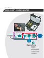
User Manual
CONNEXION® - COMMUNICATOR
Kamstrup b.v.
P.O. Box 109
NL-6980 AC DOESBURG
Leigraafseweg 4
NL-6983 BP DOESBURG
T: +31 (0) 313 - 47 19 98
F: +31 (0) 313 - 47 32 90
[email protected]
www.kamstrup.nl
User manual
2
CONNEXION® - COMMUNICATOR
CONNEXION® COMMUNICATOR DDO2110GHGB / 10.2009 / Rev. 03
CONNEXION® - COMMUNICATOR
User manual
Preface ............................................................................................................................... 4
1
Introduction.................................................................................................................. 5
®
1.1
The CONNEXION software package...................................................................................................5
1.2
The MANAGER module ........................................................................................................................5
1.3
The INSPECTOR module......................................................................................................................6
1.4
The DIAGNOSTICS module..................................................................................................................7
1.5
The COMMUNICATOR module ............................................................................................................8
1.6
System integration with business management systems ......................................................................8
2
Definitions .................................................................................................................... 9
3
Scope of supply, identification................................................................................. 10
4
COMMUNICATOR ...................................................................................................... 11
4.1
Screen setup........................................................................................................................................11
5
Synchronisation......................................................................................................... 13
6
Files ............................................................................................................................ 14
6.1
XML pressure regulator station data file..............................................................................................14
6.2
Microsoft Access pressure regulator station data file ........................................................................15
6.3
Updating the results.............................................................................................................................15
®
6.3.1
From INSPECTOR PDA to PC in XML format............................................................................15
6.3.2
From INSPECTOR PDA to PC in Microsoft Access format......................................................15
6.3.3
From PC to INSPECTOR PDA in XML format............................................................................15
6.3.4
From PC to INSPECTOR PDA in Microsoft Access format......................................................15
®
®
CONNEXION® COMMUNICATOR DDO2110GHGB / 10.2009 / Rev. 03
3
CONNEXION® - COMMUNICATOR
User manual
Preface
®
■
This manual provides important information on the use of the CONNEXION software. Please read
this manual carefully.
■
Various remarks and warnings in this manual are marked with symbols. Read these carefully and
take measures were necessary.
The symbols used have the following meaning:
4
REMARK
Suggestions and recommendations to make tasks easier.
NOTE
A note draws the user's attention to potential problems.
WARNING
If the procedure is not carried out correctly, data or settings may be lost.
CONNEXION® COMMUNICATOR DDO2110GHGB / 10.2009 / Rev. 03
CONNEXION® - COMMUNICATOR
User manual
1
Introduction
1.1
The CONNEXION® software package
The Kamstrup inspection system for pressure regulator stations consists of two main parts: the portable
®
®
PLEXOR test device and the CONNEXION software package.
®
With the portable and easy to handle PLEXOR test device the performance of the main components of a
pressure regulator station is meticulously tested. Reliable quantitative inspection results are achieved.
®
The PLEXOR test device is connected to the pressure regulator station by means of specially designed safe
measuring and diagnosis couplings that are permanently installed in the pressure regulator stations.
The inspection results obtained out of the above functional inspection of the pressure regulator station are
automatically stored in a hand-held personal computer (PDA) without any specific action by the inspector
being required.
The results of the visual inspection are entered manually. In this way, the condition of the installation is
exactly recorded.
®
In the CONNEXION software package the specific procedures used by the energy company for performing
A and B inspections can be entered.
®
The CONNEXION software package as a whole consists of four complementary modules:
MANAGER, INSPECTOR, COMMUNICATOR and DIAGNOSTICS. A demo version of the DIAGNOSTICS
module is supplied as a standard.
Main characteristics:
®
•
It has been developed to be used in combination with the PLEXOR test device.
•
It performs inspections in a highly automated way on the basis of procedures already in use by the
energy company.
•
It renders a high degree of uniformity and efficiency in the performance of inspections.
•
It is suitable to perform functional inspections of components. The identity and other data of components
can be registered.
•
Its operation-oriented (not component-oriented) structure guarantees a smooth integration with existing
business management systems.
1.2
The MANAGER module
®
MANAGER is intended as a tool to organise the CONNEXION software package and to deal with inspection
procedures, pressure regulator station data and rejection boundaries.
Main characteristics:
•
Company-specific inspection procedures and methodologies can be entered.
•
There is sufficient capacity to control dozens of units from the INSPECTOR module.
•
It manages the essential data of the PLEXOR test device, such as serial number, Bluetooth address and
calibration date.
•
It manages the file locations for data exchange by the COMMUNICATOR module between INSPECTOR,
MANAGER and a business management system, if any.
®
CONNEXION® COMMUNICATOR DDO2110GHGB / 10.2009 / Rev. 03
5
CONNEXION® - COMMUNICATOR
User manual
1.3
The INSPECTOR module
INSPECTOR is intended to be used by the inspector in the field. The software will guide the inspector through
the mandatory procedure. The measuring data collected in the test are shown on screen on a real-time basis.
Main characteristics:
•
It guides the inspector through the inspection procedure in a simple way. As a result, the inspections are
fully reproducible.
•
It assists the inspector in the performance of the inspection procedure by means of auxiliary texts. The
energy company can set up inspection procedures per type of pressure regulator station.
•
It represents the status of inspections in the list of pressure regulator stations and gas control lines.
•
Clear-cut input by making use of condition codes, option lists and check lists.
•
Simple user interface and a touch screen for the operation of INSPECTOR.
•
The results from the inspection of a gas control line are stored automatically and without specific action
needed from the inspector. The inspector only needs to enter the results of the visual check manually by
means of the keyboard.
•
Measurements that are carried out during tests with the PLEXOR test device are initiated by
INSPECTOR. That considerably simplifies the execution of an inspection.
•
The actual gas pressure is displayed on a real-time basis.
•
Data are stored by INSPECTOR on an SD card.
•
The inspection results are labelled with time and date stamp.
•
The inspection results are labelled with the identity of the PLEXOR test device and the digital
manometer or manometers with which the results have been obtained (traceability).
•
Representation of the inspection results of previous and present inspections is possible.
•
Inspection results are compared against the rejection boundaries that have been entered. In case of
rejection it is reported and, after the inspection procedure has been completed, the inspection can be
repeated.
•
Software setup, inspection procedures, pressure regulator station data and rejection boundaries cannot
be modified with INSPECTOR. Alterations can be made by means of the MANAGER module.
6
®
®
CONNEXION® COMMUNICATOR DDO2110GHGB / 10.2009 / Rev. 03
CONNEXION® - COMMUNICATOR
User manual
1.4
The DIAGNOSTICS module
By using DIAGNOSTICS selections can be made of the measuring data obtained from functional inspections.
DIAGNOSTICS will import the selected data and present these graphically in the form of a condition diagram.
This graphical drawing provides insight into the condition of a pressure regulator station, a gas control line or
a component.
Main characteristics:
•
The measuring data can easily be imported, by means of a script.
•
The selected measuring data can be graphically presented. The graphical representation provides
valuable information on the performance of components.
•
Condition diagrams at different points of time can be presented in a graph (a trend graph). Such a trend
graph in a simple way enables trend analyses to be made of the condition of a component or group of
components. Condition diagram and trend graph can be selected on the basis of date.
•
The condition diagrams of gas control lines of a pressure regulator station can be combined into a
graphical drawing. With this function the performance of the gas control lines of a pressure regulator
station can be compared against each other.
•
Presentation of rejection boundaries and standard values in a condition diagram.
•
Possibility to import and apply rejection boundaries that are laid down for a gas control line.
•
Extensive zoom function.
•
Memory of data for condition and trend graphs in Oracle or Microsoft Access database format.
®
®
DIAGNOSTICS allows for selecting and importing data for condition diagrams and trend graphs on the basis
of various selection criteria. These determine which measuring data are stored in the DIAGNOSTICS
database as input for condition or trend graphs.
Example:
At a measurement of the maximum actuating pressure of a safety valve device it is defined that the
measuring data shall be saved in the database from 20 s before till 5 s after triggering of the safety device.
The required data are selected from the relevant measuring data.
As in each inspection procedure specific inspection operations are involved, the selection criteria can be
prepared as per inspection procedure.
CONNEXION® COMMUNICATOR DDO2110GHGB / 10.2009 / Rev. 03
7
CONNEXION® - COMMUNICATOR
User manual
1.5
The COMMUNICATOR module
The COMMUNICATOR module is used for the synchronisation of data between INSPECTOR, the various
applications and the database.
This module is also used for the synchronisation of data between the business management system and the
Kamstrup inspection system for pressure regulator stations.
Main characteristics:
•
Synchronisation of data between INSPECTOR, the various applications and the database.
•
It can be installed separately.
•
Input and output files in XML and/or ACCESS format can be used for data of pressure regulator stations
and for inspection results.
•
Information on INSPECTOR is shown in the COMMUNICATOR synchronisation screen, such as:
1. INSPECTOR software version
2. Most recent synchronisation date
3. PDA serial number
4. Battery status
5. Memory status
•
Status report on the synchronisation.
•
Automatic synchronisation after the PDA has been connected to the desktop PC.
1.6
System integration with business management systems
®
CONNEXION can be used in combination with all business management systems.
Thanks to this system integration the pressure regulator station data and the inspection results can be
®
exchanged between the business management system and CONNEXION .
The file format used is XML (eXtensible Markup Language). XML Scheme Definition files (XSD) are available
for a clear-cut description of the setup and information of the XML files.
®
The use of XML and XSD files relatively simplifies the system integration of CONNEXION into a business
management system.
As an option, the objects and related measuring points can be included in the inspection procedure. As a
result, the software for maintenance management can easily recognise the results of a certain measuring
point.
8
CONNEXION® COMMUNICATOR DDO2110GHGB / 10.2009 / Rev. 03
CONNEXION® - COMMUNICATOR
User manual
2
Definitions
®
®
Microsoft ActiveSync :
Program for establishing a connection between the PDA and the desktop PC.
Once the connection has been made, data can be synchronised.
Management:
Create, open, store, modify, copy, move and remove data, including alterations of
file locations.
Condition code:
Customer-specific code used by the recording of the inspection results.
®
CONNEXION :
Software package that consists of the modules MANAGER, INSPECTOR,
COMMUNICATOR and DIAGNOSTICS. A demo version of the DIAGNOSTICS
module is supplied as a standard item.
Check list:
List with condition codes; for each condition code it is shown whether it complies
with the requirements, or not.
Inspector:
Person who performs inspections.
Inspection:
A verification by a procedure performed with the aim to establish and assess the
condition of a pressure regulator station.
Inspection procedure:
Procedure to carry out an inspection.
Inspection result:
Result of an inspection.
Check list:
List which allows only one option to be selected.
Manager:
Person who is in charge of the data of CONNEXION and who takes care of the
coupling between pressure regulator stations, gas control lines and inspection
procedures.
Measuring data:
Collected data achieved in the measurement.
The measuring data are used in two ways:
1. to determine the inspection results by INSPECTOR,
2. to represent the condition diagrams.
Measurement:
Pressure reading in the functional test by means of the PLEXOR test device.
Option list:
List that presents a number of condition codes, the inspector indicating, which
condition code and/or codes apply.
PDA:
Personal Digital Assistant (hand-held personal computer).
Script command:
Specific part of an inspection procedure. An inspection procedure is sequentially
performed according to a script. A script consists of a number of script
commands.
®
®
CONNEXION® COMMUNICATOR DDO2110GHGB / 10.2009 / Rev. 03
9
CONNEXION® - COMMUNICATOR
User manual
3
Scope of supply, identification
®
CONNEXION comprises:
®
•
CONNEXION CD-ROM
This CD-ROM contains the MANAGER, INSPECTOR, COMMUNICATOR and DIAGNOSTICS software
modules.
DIAGNOSTICS is installed as a demo version and can be activated and registered later by means of a
code, if preferred. COMMUNICATOR in an XML version can also be activated and registered later, if
preferred.
•
Instruction card with brief installation description.
The INSPECTOR module is supplied as a robust and explosion-proof hand-held computer (zone 2 in
conformity with ATEX Ex II 3G EEx nL IIC T4).
10
CONNEXION® COMMUNICATOR DDO2110GHGB / 10.2009 / Rev. 03
CONNEXION® - COMMUNICATOR
User manual
4
COMMUNICATOR
The COMMUNICATOR module is used for the synchronisation of data between INSPECTOR, the various
®
applications and the various Microsoft Access databases.
COMMUNICATOR can also be used for the synchronisation of data between the business management
system and the Kamstrup inspection system for pressure regulator stations.
If a PDA is connected to the PC, COMMUNICATOR will check the serial number. The synchronisation data
are retrieved on the basis of this serial number. In the MANAGER module these synchronisation data are set
up for the PDA (see the MANAGER user manual).
It is possible to create a connection with a business management system. In case of a connection an
activation code is necessary for each PDA.
4.1 Screen setup
1
2
3
4
8
5
6
7
9
1. Title bar and indicator bar. The status of the connection of the PC with the PDA is indicated by the colour
of the indicator bar:
•
Blue: no connection.
•
Yellow: connection present, synchronisation started.
•
Red: connection present, synchronisation stopped due to problems.
•
Green: connection present, synchronisation completed successfully.
2. INSPECTOR:
•
PDA serial number: the unique serial number of the PDA.
•
Current version: the actual version of the INSPECTOR software on the PDA.
•
New version: the version of the new INSPECTOR software available on the PC.
CONNEXION® COMMUNICATOR DDO2110GHGB / 10.2009 / Rev. 03
11
CONNEXION® - COMMUNICATOR
User manual
3. Last data exchange:
•
Time of latest data exchange with INSPECTOR.
•
Date of latest data exchange with INSPECTOR.
4. Device information:
•
Operating system: the operating system of the PDA.
•
Type processor: the processor type of the PDA.
•
Device Information: name of the PDA.
•
IP address.
5. Battery:
•
Status: status of the battery.
•
Life: total time available.
•
Full time: time left.
•
Life percent: percentage that battery is loaded.
•
AC line: is PDA connected to external current supply?
6. Memory:
•
Memory: total memory capacity.
•
Available: memory capacity available.
•
Percentage available: memory percentage available.
7. Storage:
•
Total: total storage capacity available.
•
Free: storage capacity available.
•
Percentage used: storage percentage available.
8. Progress bar with specified information per process.
9. Progress screens:
12
•
Above:
Progress in the copying of files
•
Below:
Progress in the synchronisation as a whole
CONNEXION® COMMUNICATOR DDO2110GHGB / 10.2009 / Rev. 03
CONNEXION® - COMMUNICATOR
User manual
5
Synchronisation
The synchronisation process consists of the following steps:
1. Reading the PDA data.
2. Reading the PDA serial number.
3. Allocation of data folders depending on the PDA serial number.
4. Creation of a temporary folder for the PDA data.
5. Determination when the latest data exchange with the PDA has taken place.
6. Import of the PDA data files.
7. Processing the inspection results. The inspection results will be stored by INSPECTOR in the Results.xml
file. There are two options, depending on the setup selected:
®
•
The inspection results are stored in the Microsoft Access Result.mdb database.
•
The inspection results from the Results.xml file are processed in the business management system.
8. If the data have been processed correctly, the inspection procedures, the inspection results and the
measuring data files are deleted from the PDA.
9. Generation of a file with information on the pressure regulator station. Depending on the configuration:
®
•
all the pressure regulator stations from the Microsoft Access PRS.mdb database are saved on the
PDA, or
•
the various XML files with pressure regulator stations are processed.
10. Creation of an XML file (ResultsLast.xml) which contain the latest measuring results.
11. Deleting the pressure regulator station data and the inspection status from the PDA.
12. Copying the most recent pressure regulator station data, the XML file (ResultsLast.xml) with the latest
measuring results and inspection procedures to the PDA.
13. Storage of date and time of the latest synchronisation on the PDA.
CONNEXION® COMMUNICATOR DDO2110GHGB / 10.2009 / Rev. 03
13
CONNEXION® - COMMUNICATOR
User manual
6
Files
At the first startup of COMMUNICATOR the system configuration shall be determined.
At first it has to be determined whether the pressure regulator station data, the gas control lines and the
®
rejection boundaries are retrieved from the Microsoft Access PRS.mdb database (select: ACCESS) or from
the business management system (select: XML). In the latter case the business management system
supplies the pressure regulator station data, the gas control lines and the rejection boundaries to the
StationInformation.xml file. This selection can be made in the screen below:
®
Then it has to be determined whether the inspection results in the Microsoft Access Result.mdb database
(select: ACCESS) shall be stored or that the inspection results from the Results.xml file shall be processed in
the business management system (select: XML). This selection can be made in the screen below:
®
In case of a stand-alone configuration, Microsoft Access shall be selected (select: ACCESS/ACCESS).
In case of a connection with a business management system, the choice depends on the preferred
arrangement of the connection.
6.1 XML pressure regulator station data file
If a business management system is used, the pressure regulator station data file can be stored as an XML
file.
COMMUNICATOR combines the pressure regulator station data files into a single file. As a result, the
business management system can create more pressure regulator station data files to be operated.
The pressure regulator station data files are combined using the following procedure:
•
The basic items for finding out which file is the most recent one, are date and time of the pressure
regulator station data files.
•
The most recent file is taken as the basic file, as it contains the most recent data.
•
The remaining files are handled in chronological order, starting with the most recent one.
•
Only pressure regulator stations are added that are not yet present in the basic file.
•
Pressure regulator stations that have not yet been inspected but are present in the pressure regulator
station data file on the PDA, are added to the basic file.
14
CONNEXION® COMMUNICATOR DDO2110GHGB / 10.2009 / Rev. 03
CONNEXION® - COMMUNICATOR
User manual
The result is a file that contains a unique list of pressure regulator stations stating, for each pressure
regulator station:
•
the most recent data from the business management system and
•
the pressure regulator stations that have not yet been inspected.
6.2 Microsoft® Access pressure regulator station data file
®
All the pressure regulator stations present in the Microsoft Access database (PRS.mdb) are stored on the
PDA.
6.3 Updating the results
6.3.1
From INSPECTOR PDA to PC in XML format
INSPECTOR stores the inspection results in the Results.xml XML file. In the synchronisation process the
Results.xml XML file is taken from the INSPECTOR PDA. If the Results.xml XML file is not available on the
PC, it will be created, otherwise the data are added to the file already present.
6.3.2
®
From INSPECTOR PDA to PC in Microsoft Access format
®
All the measuring results are stored in the Microsoft Result.mdb database.
6.3.3
From PC to INSPECTOR PDA in XML format
The business management system can create more StationInformation.xml XML files, if needed. In the
synchronisation process all the data are added to a StationInformation.xml XML file. Of the pressure regulator
stations and gas control lines present on the INSPECTOR PDA, only the most recent and current inspection
results are available.
6.3.4
®
From PC to INSPECTOR PDA in Microsoft Access format
In the synchronisation process the latest inspection result for a pressure regulator station and/or gas control
line is added to the ResultsLast.xml XML file and sent from the PC to the INSPECTOR PDA.
CONNEXION® COMMUNICATOR DDO2110GHGB / 10.2009 / Rev. 03
15
Kamstrup b.v.
PO Box 109
NL-6980 AC Doesburg
Leigraafseweg 4
NL-6983 BP Doesburg
TEL: +31 (0) 313 – 47 19 98
FAX: +31 (0) 313 – 47 32 90
[email protected]
www.kamstrup.nl
16
CONNEXION® COMMUNICATOR DDO2110GHGB / 10.2009 / Rev. 03
DDO2110GHGB/10.2009/Rev. 03
CONNEXION® - COMMUNICATOR
User manual