1
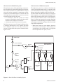
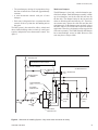
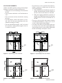
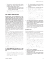
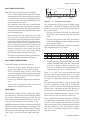
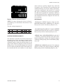
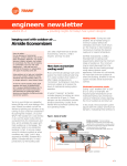
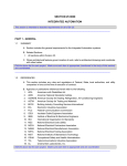
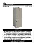
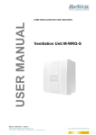
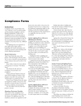
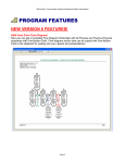
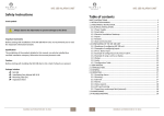
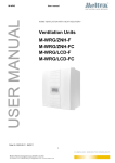
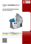
MULTIZONE APPLICATION
OF SOLUTION UNITS
APPLICATION GUIDE
Supersedes: 102.20-AG12 (206)
GENERAL
Multi-zone heating and air conditioning units offer
design and application advantages over various smaller
single zone machines. As a result, many consulting
engineers have favored them for years. Multi-zone units
are the ‘tried and true’ workhorse of the industry.
The YORK Solution unit is designed to carry on that
tradition by including a multi-zone (MZ) segment into
the design of the unit.
FUNDAMENTALS OF DELIVERY SYSTEMS
All-air delivery systems are capable of heating, cooling,
ventilation and dehumidification and provide a way of
supplying conditioned air to the specific conditioned
spaces or zones. When there is more than one zone to
be served, there must be a means by which each zone
has some control over the air-conditioning effect in
that zone.
Conditioned air can be supplied in one of two ways. A
Single-path system can be used or a dual-path system.
Single-path System
Single-path systems configure the primary heating and
cooling coils in a series flow path. The common duct
used for air distribution supplies the single-zone with
just one temperature control. This is the simplest type
of all air systems. For this type of system to work properly, the load must be uniform all through the space, or
else there may be a large temperature variation. Single
zone systems are, in most cases, controlled by varying
the quantity of chilled water or refrigerant, variable air
volume, adding reheat, adjusting face or bypass dampers, or a combination of these. If humidity control is
required while in the cooling mode, a reheat system
must be used.
Dual-path System
Dual-path systems place the cooling coils and heating
coils in separate ducts in which the air from the supply
fan is split into two parallel paths, one for heating and
the other for cooling. The two parallel paths provides
for great flexibility in satisfying multiple loads and in
providing prompt and opposite temperature response
Form: 102.20-AG12 (307)
as required. Dual path systems mix the hot and cold air
at each zone at all times. A dual path system may be
either a dual-duct system or a multi-zone system. These
two systems are similar in thermal dynamics, how they
affect temperature, pressure, volume, mechanical action,
and function; they differ only in the physical layout of
where the system mixes the air for each zone.
DESIGN CONSIDERATIONS
Possible Applications
Multi-zone and Dual Deck air-handling units can be
configured for heating and cooling, or cooling and
ventilation, or ventilation and heating applications. The
historical concept behind most MZ applications was to
typically maintain 55° and 95° air at all times. As maintaining the hot deck proved expensive, especially in the
southern regions where it is rarely used, the hot deck
became a bypass deck. In cases where some heating was
still required those zones received a heating coil. This
development proved to be the most economical.
The concept of bypass allowed a “dead band” between
heating and cooling where the space is merely ventilated with blended return air and outside air. One of the
more innovative implementations of this concept is in
the use of the traditional hot-deck to supply neutral air
from a dedicated outdoor air unit to the VAV boxes.
Another variation of this strategy is referred to as the
Texas multi-zone.
Cooling Coils
For the purposes of this discussion we will refer to
cooling coils as ‘Chilled Water’ coils. The alternative
would be to discuss both chilled water coils and direct
expansion (DX) coils. Simply stated; DX coils applied
in multi-zone systems can be very sophisticated. The
selection of the coil, coil circuiting and the condenser
should be reviewed with the system application for
correct system operation. Potential risks with DX coil
applications include but not limited to; low cooling load
and compressor cycling, resulting in poor cold deck
control and compressor failures. A special application
review should be requested when a multi-zone DX
cooling system is being considered.
FORM: 102.20-AG12 (307)
Characteristics of Dual Duct System
Characteristics of Multi-zone System
The dual-duct system, while maintaining a constant airflow, distributes air to the building through two separate
ducts. Hot and cold ducts are extended into the occupied
areas with mixing terminals for temperature control
located over the conditioned spaces. The hot and cold
air brought by the separate ducts to each zone is then
mixed to meet the needs of the zone.
• It is common for dual-duct systems to use high
pressure air distribution systems with the pressure
reduced in the mixing box at each zone.
• A thermostat controls each zone in the system.
The multi-zone system is a variation of the dual-duct
system. The traditional multi-zone is a constant volume
system that maintains room air changes, and space temperature and relative humidity with great precision.
Dual-duct systems are used in larger buildings where
it would be impractical to run a separate duct from
the air-handler to each zone as is done in multi-zone
systems. A simple dual-duct system is illustrated in the
figure 1 below:
The basic Multi-zone (MZ) unit consists of a supply air
blower segment, a coil segment and discharge air elements. Other sections such as filters, air mixing boxes,
access, and full economizer with a return/exhaust air
blower is offered to customize the systems functional
requirements. The unit discharge is available with multizone dampers or dual-duct openings either in horizontal
or up-blast configurations.
• Multi-zone systems use zone dampers, located at
the air unit, to mix heated air from a heating coil
and chilled air from a chilled water coil to regulate
the air temperature for a space, or zone.
EXHAUST AIR
RELIEF DAMPER
RETURN
FAN
CEILING PLENUM
OR RETURN DUCT
RETURN AIR
MIXING BOXES
(TYP)
RETURN
AIR
DAMPER
HEATING
COIL
OUTSIDE
AIR
DAMPER
OUTSIDE
AIR
SUPPLY
FAN
COOLING
COIL
RETURN
(TYP)
ZONE 1
SUPPLY
(TYP)
ZONE 2
ZONE 3
Figure 1 – Basic Dual Duct Air Handling System
2
JOHNSON CONTROLS
FORM: 102.20-AG12 (307)
• The zone dampers, mixing air in proportions, keep
the flow of mixed air to each zone approximately
constant.
• A zone thermostat controls each pair of zone
dampers.
• Each zone is designed to have a separate duct that
extends all the way from the air-handling unit to
the space.
The MZ system is best suited for offices, schools and
other similar buildings where a relatively small space
requires independent zone thermostatic control. See
figure 2.
Multi-zone Dampers
The MZ damper is a low-leak, vertical orientation, parallel blade damper. Each MZ damper assembly is made
up of two dampers, one for the cold deck and one for
the hot deck. The damper blades for the hot and cold
decks are linked together and offset by 90°. Therefore,
one actuator may operate the cold deck and hot deck
simultaneously. As the damper opens one deck it closes
the other, and vice versa. Each zone requires an actuator
application. Therefore, calculate the torque required for
each zone separately. The YORK Solution MZ damper
has a constant height across its width. However, each
zone may have a unique width.
EXHAUST AIR
Optional Manual Volume Damper
CEILING PLENUM
OR RETURN DUCT
RELIEF DAMPER
RETURN
FAN
RETURN AIR
RETURN AIR
DAMPER
ZONE DAMPERS
(TYP)
HOT DECK
HEATING COIL
OUTSIDE AIR
DAMPER
OUTSIDE
AIR
SUPPLY
(TYP)
RETURN
(TYP)
SUPPLY
FAN
COLD DECK
COOLING COIL
ZONE 1
ZONE 2
ZONE 3
Figure 2 – Multizone Air Handling System—Only three zones are shown for clarity
JOHNSON CONTROLS
3
FORM: 102.20-AG12 (307)
SOLUTION MZ SEGMENTS
A Multi-zone (MZ) segment is used to provide multiple
discharge air-streams to specific building zones.
• Each zone receives two discharge-air streams from
the MZ.
• One air-stream is defined as “cold” and the other as
“hot.”
• These air-streams are then mixed before entering
the space.
• The MZ damper controls the balance of “hot”
and “cold” air to the space depending on the zone
demand for heating or cooling.
• The part of the MZ that supplies “cold” air is called
the “cold deck,” and the part that supplies “hot” air
is called the “hot deck.”
Cold Deck Damper
• The bottom tier is the cold deck and contains a
diffuser or plenum, a chilled water coil and cold
deck-zoning dampers.
1. When a DWDI fan is immediately upstream of
the MZ, then the MZ must include a diffuser as
the first section in the bottom tier of the MZ.
2. When the segment immediately upstream of
the MZ is not a DWDI fan, then an access plenum
will be the first section in the bottom tier of
the MZ.
• The top tier is the hot deck and contains a heating
coil mounted horizontally (configured for vertical
air flow) and hot deck-zoning dampers.
• Air enters at the diffuser or plenum then splits into
two streams. One stream turns up through the hot
deck coil and exits the rear or top of the unit through
the hot deck damper. See Figures 3 and 4.
Cold Deck Damper
Hot Deck Damper
Hot Deck Damper
HEATING COIL
HOT DECK
HOT DECK
S1
XA
HEATING OR COOLING COIL
AIR FLOW
ENTERING
MZ
RACEWAY
RACEWAY
HEATING OR COOLING COIL
S1
VC
VC
DI^
RACEWAY
RACEWAY
Hot Deck Damper
HEATING COIL
HEATING COIL
HOT DECK
XA
DI^
SIDE VIEW
Figure 4 – Rear Discharge Flow w/Diffuser
HEATING OR COOLING COIL
RACEWAY
RACEWAY
AIR FLOW
ENTERING
MZ
Cold Deck Damper
HOT DECK
HEATING OR COOLING COIL
Cold Deck Damper
XA
Figure 5 – Top Discharge Flow w/o Diffuser
RACEWAY
RACEWAY
Hot Deck Damper
Figure 3 – Top Discharge Flow w/Diffuser
4
AIR FLOW
ENTERING
MZ
SIDE VIEW
SIDE VIEW
VC*
FH+.75
HEATING COIL
RACEWAY
FH+.75
INSULATED WALL
RACEWAY
RACEWAY
RACEWAY
INSULATED WALL
2.750
VC*
AIR FLOW
ENTERING
MZ
XA
SIDE VIEW
Figure 6 – Rear Discharge Flow w/o Diffuser
JOHNSON CONTROLS
FORM: 102.20-AG12 (307)
• The other stream continues horizontally through
the chilled water coil and exits the rear or top of
the unit through the cold deck damper.
1. Air pressure drop balance plates are to be used
to equalize pressure drop across the hot and
cold deck coils when required.
• When a DWDI fan is immediately upstream of the
MZ, then the fan configuration shall be a horizontal
inverted discharge.
ANSI / ASHRAE / IESNA LIMITATIONS
Increasing energy costs have limited the use of conventional MZ systems, which use more energy than
certain single duct configurations when it is necessary to
both heat and cool supply air and mix the airstreams to
obtain the desired zone temperature and humidity. It is
important to control MZ systems to limit simultaneous
heating and cooling as much as possible. By far the largest opportunity for energy conservation in a multi-zone
re-heat system is minimizing the mixing of hot and cold
air. You can radically reduce energy losses by adjusting
the discharge temperatures or supply air temperatures
of the heating and chilled water coils. Automatic supply
air temperature reset controls are available to maintain
optimum temperatures. These methods are relatively
inexpensive.
However, we must mention the limitations placed on
MZ systems by ANSI/ASHRAE/IESNA Standard 90.12004 – Energy Standard for Buildings Except Low-Rise
Residential Buildings. These limitations can be found
on page 38 of the 2004 Standard and 6-54 of the 2004
User’s Manual. Standard 90.1, per section (6.5.2.1),
requires that zone thermostat controls must be capable
of sequencing the supply of heating and cooling to each
space. These controls must prevent; reheating, re-cooling, mixing or simultaneous supply of air that has been
previously mechanically heated and air that has been
previously cooled, either mechanical or by economizer
systems, or other simultaneous operation of heating and
cooling systems to the same zone.
STANDARD 90.1 COMPLIANCE
To comply with Standard 90.1-2004 (6.5.2.1), MZ
systems must use one of the three exceptions as follows:
1. Simultaneous heating and cooling is allowed if it is
minimized by limiting the airflow rate that is being
reheated, re-cooled or mixed to a rate no greater
than the larger of the following:
JOHNSON CONTROLS
a. The volume of outdoor air required to meet the
ventilation requirements of standard 6.1.3 of
ASHRAE.
b. 0.4 cfm/ft2 of the zone conditioned floor area
c. 30% of the zone design peak supply rate
d. 300 CFM – this exception is for zones whose
peak flow rate totals no more than 10% of the
total fan system flow rate.
e. Any higher rate that can demonstrated, to the
satisfaction of the authority having jurisdiction,
to reduce overall system annual energy usage by
offsetting reheat/re-cool energy losses through
a reduction in outdoor air intake in accordance
with the multiple space requirements defined
in ASHRAE Standard 62
2. Zones where special pressurization relationships,
cross-contamination requirements, or code-required
minimum circulation rates are such that variable air
volume systems are impractical.
3. Zones where at least 75% of the energy for reheating
or for providing warm air in mixing systems is provided from a site-recovered (including condenser
heat) or site-solar energy source.
DESIGNING TIPS
The following should be taken into consideration when
a multi-zone application is being considered:
• Designers should include a manual opposed blade
main volume damper near the unit to assist in air
balancing. Air quantities delivered to the conditioned spaces will vary as the static pressure fluctuates with filter loading and conditions of the chilled
water coil.
• With designs containing a considerable number of
zones, it is best to keep the zone duct static pressure
low as possible to limit leakage. Maximum duct
leakage should be around 2% of the zone supply air.
(SMACNA leakage standard allows over 10%).
• Periodically check the mixing dampers to insure
that the mixing dampers are properly positioned
and not blending air when full cooling or heating
is required.
• Specify low leak zone dampers.
• Select areas of similar loads for a zone; don’t mix
interior and exterior areas.
• Locate the sensor or t-stat in the area of the zone and
specify that the zone sensor be verified to control
the proper zone.
5
FORM: 102.20-AG12 (307)
MULTI-ZONE ADVANTAGES
Multi-zone units offer the following advantages:
• From a control standpoint the multi-zone is rather
simple and inexpensive, there is little to go wrong. If
you combine zone sensors, a mixing damper actuator for each zone, and cooling and heating valves,
you have multi-zone control.
• The simplicity of the multi-zone system includes
minimum ceiling space requirements, uncomplicated installation, and has the control elements for
mixing of the hot and cold air paths centrally located
at the air-handling unit.
• Since the multi-zone fan operates as a low static
pressure system, it is quieter. Also, the fan is located
mid position in the unit gaining fan outlet attenuation from the baffles, coils and casing. More importantly, the fan is not subject to any abnormal system
effect, eliminating fan performance problems and
the all too familiar rumble of a variable air system.
Because it operates at a lower speed, the fan can
typically be a Class I fan, which offers smooth
operation and longer bearing and drive life.
• The multi-zone will most certainly provide longevity with only minor maintenance and repairs.
MULTI-ZONE DISADVANTAGES
Some disadvantages of multi-zone units are:
• When the need for many individual ducts is
required, the number of zones could be limited
• There is potential energy waste as well as high
energy consumption due to the simultaneous heating
and cooling of the air stream and inferior temperature control of the hot deck.
• It can be very difficult to implement an economizer
cycle
• A multi-zone is generally custom selected and
arranged for ‘fixed-functional’ needs
ZONE SIZING
The following example will use a multi-zone damper
for a unit sized @ 10,000 CFM. This particular damper
has 16 zones, each zone containing a 6" blade. The end
zones for this specific damper will each be 8” wide. The
inner zones will each be 6" wide for a total of 100".
NOTE: Each end zone includes a 6" blade and a blank-off
plate sized to fit the various cabinet sizes. See Figure 7. The
total zone maximum CFM is 10,000 spread over 9 zones.
The zones have the following CFM requirements: 700;
1,000; 2,500; 1,700; 500; 400; 400; 1,000; 2,000 CFM.
6
E= NO. OF 6" SPACES
END
ZONE
D
END
ZONE
1.50
D
DIVIDER
BLADE
BLANK-OFF
PLATE
BLANK-OFF
PLATE
Figure 7 – 16 - Zone Multi-zone Damper
First determine the CFM per inch of damper length.
10,000/100" = 100 CFM/in. Therefore, the ideal CFM
for the 8" zone sections is 800 CFM, and 600 CFM for
the 6" zone sections.
• The first zone requires 700 CFM. The first blade’s
ideal CFM is 800. Assign the first zone to the first
blade.
• The next zone requires 1,000 CFM. The next two
blades’ ideal CFM totals 1,200. Assign the next zone
to the next two blades.
Continue until the second to last zone has been defined.
Zone assignments will be as follows:
1
2
8"
700
6" 6"
1000
3
6"
6" 6"
2500
4
6"
6"
5
6
7
8
9
6" 6" 6" 6" 6" 6" 6" 8"
1700
500 400 400 1000 1800
• The final zone needs 1,800 CFM but the ideal CFM
for the last available blade is only 800. The last zone
needs 20" of damper width to be properly sized.
Therefore, we must take two 6" damper blades from
a previous zone and “give” it to the last zone.
Zones 1, 5, 6, and 7 have only one blade each and
therefore cannot be made smaller. Zones 2, 3, 4, and 8
have more than one blade. Therefore, we will examine
the impact of subtracting a blade from each of these
zones.
Zone two has an ideal CFM of 1,200, and actual CFM
of 1,000 – a difference of 200 CFM. If we subtract a
blade, it will have an ideal CFM of 600 and an actual
CFM of 1,000 – a difference of 400 CFM. The ratio of
this difference to the actual CFM is 400/1000, or 0.4.
We do the same calculation for zones 3, 4 and 8, yielding
impact ratios of 0.28, 0.29, and 0.4, respectively.
Zones 3 and 4 have the smallest impact ratios. Therefore
we could take one 6" blade from each zone. However, if
you only “steal” one blade from either zone 3 or 4, then
zone 9 has an ideal CFM of 1400 and an actual CFM of
1800 for a difference of 400, which equals an impact
ratio of 0.22 – less than the impact ratio of stealing a
blade from 3 & 4.
JOHNSON CONTROLS
FORM: 102.20-AG12 (307)
(these items are typically shipped loose with each
air handler). Next, consult the job specifications and
submittal drawings for specific zoning requirements,
connection requirements, and location. It is essential
that, prior to performing any task on this equipment,
the individual responsible for installation, shall have
read and understood all the equipment documentation
and installation instructions, shipped with each unit,
for assembling.
HOT DECK
COLD DECK
Figure 8 – Multizone Controlled Dampers
REFERENCES
NOTE: For more information, please reference:
Air handling Unit Installation Instructions Form
102.20-N1.
“Fundamentals of HVAC Systems” chapter 9 & 10,
Richard R. Johnson, Ph.D., ASHRAE Society of Heating,
Refrigeration and Air-Conditioning Engineers Inc.
The final zoning arrangement is:
1
2
8"
700
6" 6"
1000
3
6"
6" 6"
2500
4
6"
5
6
7
8
6" 6" 6" 6" 6" 6" 6"
1700
500 400 400 1000
9
6" 8"
1800
CONTRACTOR RESPONSIBILITY
The individual responsible for the final connection of
the zoning ducts to the zone dampers should, before
installing the zone-ducts to the damper, check each set
of damper blades to make sure that the blades are 90
degrees apart. Rotate the dampers to make sure that no
binding occurs. Check all of the damper rods, clips and
screws to make sure that all are tight. Locate and secure
the extended shaft kits and couplers for each damper
JOHNSON CONTROLS
“Air Conditioning Design Manual”, chapter 6, ASHRAE
581-RP Project Team, 1993 American Society of Heating,
Refrigerating and Air-Conditioning Engineers, Inc.
ASHRAE. 2004. ANSI/ASHRAE/IESNA Standard 90.1
– 2004 Energy Standard for Buildings Except Low-Rise
Residential Buildings. Atlanta, GA: American Society
of Heating, Refrigerating and Air-Conditioning Engineers, Inc.
ASHRAE 2004. ASHRAE Standard 90.1 User’s Manual,
chapter 6. Atlanta, GA: American Society of Heating,
Refrigerating and Air-Conditioning Engineers, Inc.
7
P.O. Box 1592, York, Pennsylvania USA 17405-1592
© by Johnson Controls 2006
Form 102.20-AG12 (307)
Supersedes: 102.20-AG12 (206)
Tele. 800-861-1001
www.york.com
Subject to change without notice. Printed in USA
ALL RIGHTS RESERVED