1
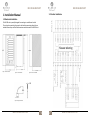
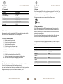
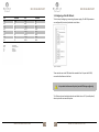
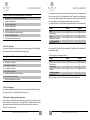
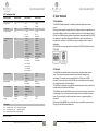
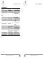
MS 10B ALARM UNIT
Safety Instructions
Table of contents
Used symbols
Always observe this information to prevent damage to the device
Important Comments
Before starting with installation of the MS 10B Alarm Unit, we recommend you to read
the important information beneath.
Qualification
The installation of the product detailed in this manual, can only be installed by a
certified installation company. Otherwise the warranty becomes void.
Caution:
Before starting with installing the MS 10B Alarm Unit, check if all parts are present.
Package includes:
MS 10B
Installation/User Manual MS 10 B
Mounting Clips (2x)
Inspection Sheet
MARBLE AUTOMATION BV © 2011
MS 10B ALARM UNIT
1
SAFETY INSTRUCTIONS ................................................................................................ 1
1. INSTALLATION MANUAL........................................................................................... 3
1.1 MECHANICAL INSTALLATION .................................................................................. 3
1.2 ELECTRICAL INSTALLATION ..................................................................................... 4
1.2.1 Power Supply ................................................................................................... 5
1.2.2 Used cable ....................................................................................................... 5
1.2.3 Electrical installation Roadmap......................................................................... 5
1.2.3 Inputs .............................................................................................................. 5
1.2.4 Outputs............................................................................................................ 6
1.2.5 Data communication ........................................................................................ 6
1.3 CONFIGURING OF THE MS 10B UNIT ...................................................................... 8
1.3.1 Roadmap of configuring MS 10B unit................................................................ 9
1.3.2 Examples of configuring inputs ....................................................................... 10
1.3.2.4 N.C. Status input ......................................................................................... 11
1.3.3 Example of configuring an oil pressure alarm.................................................. 11
1.3.4 Example of using a unit as a display ................................................................ 13
1.3.5 Delays ............................................................................................................ 14
1.3.5 Locks.............................................................................................................. 14
1.3.7 Configuration Table........................................................................................ 15
2. USER MANUAL ....................................................................................................... 16
2.1 INTRODUCTION.................................................................................................... 16
2.2 GENERAL.............................................................................................................. 16
2.3 OPERATING .......................................................................................................... 17
2.3.1 Accepting alarms............................................................................................ 17
2.3.2 Dimming ........................................................................................................ 17
2.3.3 LED-test ......................................................................................................... 17
2.3.4 Alarms ........................................................................................................... 17
2.3.5 Status reports ................................................................................................ 18
2.3.6 LED synchronizing .......................................................................................... 18
2.3.7 Cancel horn and accept flash (external) .......................................................... 18
2.3 MAINTENANCE .................................................................................................... 18
2.4 TROUBLESHOOTING ............................................................................................. 19
2
MARBLE AUTOMATION BV © 2011
MS 10B ALARM UNIT
MS 10B ALARM UNIT
1.2 Electrical Installation
1. Installation Manual
Figure 5. Wiring diagram
1.1 Mechanical Installation
The MS 10B unit is specially designed for mounting in a switchboard or desk.
The unit can be mounted in the panel or desk with two mounting clips which are
included. Beneath you will find the dimensions needed to mount the MS 10B unit.
Nieuwe tekening
Figure 1. Front view MS 10B
Figure 2. Side view MS 10B
Figure 3. Panel cut out MS 10B
Figure 4. Wiring space MS 10B
MARBLE AUTOMATION BV © 2011
3
4
MARBLE AUTOMATION BV © 2011
MS 10B ALARM UNIT
1.2.1 Power Supply
Description
Supply voltage
Power consumption
Digital inputs
Digital lock inputs
Group outputs
Relay output
1.2.4 Outputs
The unit has 3 outputs 24V DC, which can deliver an maximum of 500 mA each. These
outputs are available at the terminals 20-23. Terminal 20 is the common ground for the
outputs. Make sure the common ground will be used.
Specification
18-30 Vdc
2,7 Watt
10 (N.C./N.O.)
3 (N.C./N.O.)
3 (N.E/N.N.E) 500mA
1 (N.O.)
The three group outputs can be configured in three different ways:
Level
Dip
LED-copy
Table 1. Power supply specifications
1.2.2 Used cable
Recommended is a shielded twisted cable (LIYCY). Connect shield at one end only. The
end of the shield must be insulated with tape or insulating tube.
1.2.3 Electrical installation Roadmap
1. Pull the connectors from the unit.
2. Connect the wires to the connectors.
3. Turn the breaker of the supply on.
4. Check voltage polarity of the power supply.
5. Turn breaker off.
6. Plug the connectors to the unit.
7. Turn breaker on.
8. Check if the unit is working, the green LED will Flash.
9. Test channels and output wiring. The software is in default setting.
10. When the MS 10B unit operates , configuring can be started.
1.2.5 Data communication
The MS 10B is equipped with an RS485 communication port. Using this port it is
possible to link two or more units. The one is set as ‘master’ and the other ones as
‘slave’. The master unit has the channels connected. The slave unit will follow the
master-unit as a second display.
The cancel horn/accept flash buttons work remotely on all units. When local cancel
horn an accept flash functionality is preferred, ‘slave 4’ mode should be set.
It is also possible to connect a PLC as master and the MS 10B as slave. This gives the
possibility to create networks with a PLC system as a main Alarm system and the
MS 10B as sub-systems.
1.2.3 Inputs
The unit has 10 inputs (channels). The inputs are connected to the terminals 2 – 11.
Terminal 1 is the common ground, which should always be used.
Inputs can be configured as an Alarm input or as a Status input. Both input types can be
configured as Normally Open (N.O.) or as Normally Closed (N.C.) input.
MARBLE AUTOMATION BV © 2011
MS 10B ALARM UNIT
5
Description
Communication Interface
Protocol
Baudrate
Databits
Parity
Stopbits
Slave-ID
Modbus functions
Specification
RS-485
Modbus-RTU
19200
8
None
8
1 - 100
3&6
Table 2. Data communication specifications
6
MARBLE AUTOMATION BV © 2011
MS 10B ALARM UNIT
Bit
B0
B1
B2
B3
B4
B5
B6
B7
Function
N.U.
I1
I2
I3
I4
I5
I6
I7
Bit
B8
B9
B10
B11
B12
B13
B14
B15
MS 10B ALARM UNIT
1.3 Configuring of the MS 10B unit
Function
I8
I9
I10
A.H.
A.F.
N.U.
N.U.
N.U.
The first step of configuring is connecting the power supply. The MS 10B parameters
are configured by four rotary knobs and a save button.
Table 3. Bit functions
B0-B15
I0-I15
N.U.
A.H.
A.F.
: Bit 0 t/m Bit 15
: Input 1 t/m Input 15
: Not Used
: Accept Horn
: Accept Flash
Figure 6. Inside MS 10B
These switches are on the PCB behind the removable front. To open the MS 10B,
remove the black frame at the front.
It is permitted to disconnect the front from the PCB during configuring!
The 10 alarm channels and status channels are default set as a N.C. (normally closed)
alarm input with one second delay time.
MARBLE AUTOMATION BV © 2011
7
8
MARBLE AUTOMATION BV © 2011
MS 10B ALARM UNIT
1.3.1 Roadmap of configuring MS 10B unit
For programming the MS 10B, the steps on the following page have to be performed.
To start configuring, the power supply has to be connected!
Step 1: Function Selection
Switch 1 configures the function on the PCB. There are 10
different functions available, which are described in the
Configuration Table (page 13).
MS 10B ALARM UNIT
Continuation of Roadmap MS 10B unit
Step 4: Save settings
The settings chosen with switch 1, 2 and 3 will be saved by
pressing the save button.
You will find the save button above the four selector switches.
The settings will be saved in the retain memory of the
MS 10B.
Repeat this step after each setup!
The Configuration Table is also displayed on the side of the
MS 10B unit.
After the settings are saved, LED 1 to 10 will reflect the settings
3 and 4.
If Switch 1 is in the normal operation mode (position 1), the
power LED will flash. During configuring the power LED will
light steady.
The setting of switch 3 is reflected by a slow flashing LED, the
setting of switch 4 is shown by a fast flashing LED. If the settings of switches 3 and 4
have the same setting, the LED will light steady.
After configuring, switch 1 has to be set to position 1, otherwise the MS
10B unit will not work!
After configuring, switch 1 has to be set to position 1, otherwise the MS
10B will not work!
Step 2: Input / Output Selection
Switch 2 will select the input or output selected with switch 1.
Table 5. Continuation of table 4
If function 9 is chosen in step 1, switch 2 can only be used for the master or slave
selection.
1.3.2 Examples of configuring inputs
1.3.2.1 N.O. Alarm input
If an input is configured as a N.O. alarm input, then after closing the contact,
the corresponding LED will flash and the potentially free output will close.
Step 3: Input / Output parameters
Switches 3 and 4 are used to configure settings of the function chosen with switch
These will work in combination with the input or output chosen with switch 2.
1.3.2.2 N.C. Alarm Input
If an input is configured as a N.C. alarm input, then after opening the contact,
the corresponding LED will flash and the potentially free output contact will close.
Table 4. Roadmap of configuring MS 10B unit
MARBLE AUTOMATION BV © 2011
9
10
MARBLE AUTOMATION BV © 2011
MS 10B ALARM UNIT
MS 10B ALARM UNIT
To prevent false alarms, the channel is given a delay of 5 seconds. If the engine stops,
the oil pressure will drop. This will generate an alarm. To prevent this, we are going to
use the running signal contact of the diesel engine as a lock. To prevent a false alarm
when the engine is started, the Lock is given an off delay of 9 seconds.
To configure the delay, use the following configuration settings in the table beneath.
Example 1: Channel 3 has to be configured as a N.C. alarm input
1 Remove the front frame and the front of the unit
2 Set switch 1 at position 2
3 Set switch 2 at position 3
4 Set switch 3 at position 1
5 Set switch 4 at position 1
6 Push the save button to save the settings
7 Set switch 1 back at position 1
8 Place the front and the front frame
Subject
Delay
Channel input
Delay
Delay-time (5 seconds)
Press the save-button
Table 6. Configuring N.C. alarm input
Switch
1
2
3
4
position
3
5
0
5
Table 8. Configuring the delay
1.3.2.3 N.O. Status input
If an input is configured as a NO status report, the corresponding LED will only display
the status of the input. The LED will light if the input is high.
After saving LED 10 (for 0) will flash slowly and LED 5 will flash fast. This reflects the 5
seconds delay setting.
The following step is to configure the Lock.
Subject
Switch
Lock
1
Channel input
2
Running signal
3
Not used
4
Press the save button
Example 2: Channel 7 has to be configured as a N.O. status input
1 Remove the front frame and the front of the unit
2 Set switch 1 at position 2
2 Set switch 2 at position 7
3 Set switch 3 at position 2
4 Set switch 4 at position 2
5 Push the save button to save the settings
6 Set switch 1 back at position 1
7 Place the front and the front frame
Table 9. Configuring the lock
After the setting is saved, LED 4 will flash slowly and LED 10 flashes fast.
Table 7. Configuring N.O. status input
1.3.2.4 N.C. Status input
If an input is configured as a NC status report, the corresponding LED will only display
the status of the input. The LED will light if the input is low.
1.3.3 Example of configuring an oil pressure alarm
As an example we will configure the “oil pressure low” alarm of a diesel engine. The oil
pressure contact on the engine is N.C. (Normally Closed). The alarm has to occur when
the pressure drops, the switch will then open. We want to configure this alarm on
channel 5 as “oil pressure low”.
MARBLE AUTOMATION BV © 2011
position
5
5
4
0
11
12
MARBLE AUTOMATION BV © 2011
MS 10B ALARM UNIT
Now we have to configure the settings of the lock.
Subject
Switch
Lock-settings
1
Lock selection
2
Lock configuration setting
3
Seconds
4
Press the save button
MS 10B ALARM UNIT
1.3.5 Delays
It is possible to configure delays on the inputs or outputs of the MS 10B. The delay
prevents false alarms generated by fast reaction times of a sensor or when automatic
recovery must take place.
position
6
3
6
9
Example 3: Channel 5 has to be delayed for 5 seconds
1 Remove the front frame and the front
2 Set switch 1 at position 3
3 Set switch 2 at position 5
4 Set switch 3 at position 5
5 Push the save button to save the settings
6 Set switch 1 back at position 1
7 Replace the front and the front frame
Table 10. Configuring lock settings
After configuring, switch one has to be set to position 1, otherwise the
unit will not work.
Table 12. Delay channel 5
1.3.4 Example of using a unit as a display
1.3.5 Locks
A lock is used to block any alarm or status report, when it is not necessary to display
the alarm or status. This is usually the case with alarms on engines. These alarms are
blocked when the engine is at standstill. The locks are free configurable for each
channel and can be set with an “on” or “off” delay. The units has 3 lock-inputs. The
locks can be connected to the terminals 13-15. Terminal 16 is the ‘common ground’.
Which should always be used.
Example 8: Unit 2 has to be used as a display of unit 1
1
Remove the front frame and the front of unit 1
2
Set switch 1 at position 9
3
Set switch 2 at position 1
4
Push the save button to save the settings
5
Set switch 1 back at position 1
6
Replace the front and the front frame of unit 1.
7
Unit 1 is now ready to be used as Master.
8
Remove the front frame and the front of unit 2
9
Set switch 1 at position 9
10 Set switch 2 at position 2
11 Set switch 3 at position 0
12 Set switch 4 at position 0
13 Push the save button to save the settings
14 Set switch 1 back at position 1
15 Replace the front and the front frame of unit 2.
16 Unit 2 is now ready to be used as slave.
These connections are only needed if the option
‘Lock by lock input’ will be used.
Table 11. Example of display use
MARBLE AUTOMATION BV © 2011
13
14
MARBLE AUTOMATION BV © 2011
MS 10B ALARM UNIT
1.3.7 Configuration Table
Switch 1 Function
Switch 2 Channel
Switch 3 Setting
Switch 4 setting
1. Alarm mode
2. Input mode
Not Used
1 - 10
Not used
1. Alarm
2. Status
3. Input delay
4. Lock by channel
1 - 10
1 - 10
5. Lock inputs & Group
outputs
1 - 10
6. Lock settings
1-3
Not used
1. N.C.
2. N.O.
0 - 99 sec.
st
1 Lock
CH. 1 - 9
10 - No lock
1. Lock 1
2. Lock 2
3. Lock 1, 2
4. Lock 3
5. Lock 1,3
6. Lock 2,3
7. Lock 1, 2 and 3
10. No locks
1. N.C. Direct
2. N.O. Direct
3. N.C. Delay on
4. N.O. Delay on
5. N.C. Delay off
6. N.O. Delay off
1. Level
2. Dip
3. Led copy
On delay
1-10 Seconds
* Slave setting
1-99 Slave ID
00 - Follow master
MS 10B
1. Level
2. Dip
* Slave setting
7. Output settings
1-3
8. Output delays
1-3
9. Communication
1. Master
2. Slave
3. Slave WB
10. None
1. Default
2. Relay
10. Set default & Relay
settings
MS 10B ALARM UNIT
2. User manual
2.1 Introduction
The MS10B of Marble Automation is a flexible system that handles alarm /status
reports.
By using a micro controller in combination with configure switches, the parameters can
simply be modified on site by the user without the need for a PC with configure facility.
Also the use of SMD technology instead of conventional components makes the MS10B
very compact. It is possible to join several MS10B units to each other and let them
interface with each other. The MS10B can be used in shipping as well as industrial
applications.
The MS10B has been type approved by Lloyds Register (07/30018) and Bureau Veritas
(21072/A0).
nd
2 . Lock
CH. 1-9
10. No lock
1. Lock 1
2. Lock 2
3. Lock 1, 2
4. Lock 3
5. Lock 1,3
6. Lock 2,3
7. Lock 1, 2 and 3
10. No output
Lock delay
1-10 Seconds
2.2 General
The MS10B has ten channels which can be used either as an alarm input or status
input. These channels are galvanic isolated from the internal feeding part by
optocouplers. The internal circuit is separated from the 24V net with a DC/DC
converter. The three lock inputs of the MS 10B unit can be linked to the alarm inputs,
which makes it possible to block the alarms.
The MS10B unit is equipped with an RS-485 communication port which can be used to
interface with other systems or MS10B units.
The MS10B unit has one potential free relay contact that can be used to control a horn
or rotating light. There are three transistor outputs which can be linked to the alarm
inputs. They can be used to relay the main alarm system or to generate switching
commands.
When using multiple MS10B units next to each other it is possible to synchronize the
LED-lights so they will flash simultaneously.
1. N.N.E.
2. N.E.
Off Delay
1-10 Seconds
1. N.N.E.
2. N.E.
Abbreviations:
N.C. : Normally Closed N.N.E. : Normally Not Energized
N.O. : Normally Opened N.E. : Normally Energized
W.B. : Without Buttons Accept horn/Accept flash
Table 13. Configuration table
MARBLE AUTOMATION BV © 2011
15
16
MARBLE AUTOMATION BV © 2011
MS 10B ALARM UNIT
2.3 Operating
2.3.1 Accepting alarms
To cancel the horns, press the ‘cancel Horn’ button. After that the ‘accept’ button can
be pressed. This will cause the Led to light steady or turn off if the alarm has recovered.
MS 10B ALARM UNIT
2.3.5 Status reports
If an input is configured as a status report, this channel will only display the status of
the input. The LED will light if the input is high or low, depending on the N.O./N.C.
settings. When set as status report the potential free relay contact will not operate.
2.3.6 LED synchronizing
The LED synchronizing can be applied if more than one MS 10B units are being used,
placed next to each other. If the Led synchronizing inputs en outputs are connected to
each other than the power and alarm LED’s will flash simultaneously.
2.3.7 Cancel horn and accept flash (external)
If more MS 10B units are placed next to each other, cancel horn and accept flash
buttons can be joined by connecting the corresponding terminals. Each button that is
pressed, will work for every unit.
Figure 7. Cancel horn and accept
2.3.2 Dimming
The backlight of the MS 10B can be dimmed by pressing the ‘Cancel Horn’ button and
holding it until the desired light setting is reached. The power LED can be dimmed by
holding the ‘Accept’ button.
2.3.3 LED-test
The LED lights can be tested by pressing the ‘Cancel Horn’ and ‘Accept’ buttons at the
same time. All LED lights should light up.
2.3.4 Alarms
When an input is configured as alarm input and the alarm contact opens or is closed
depending on N.O./N.C. setting, the corresponding LED will flash and the potential free
contact will close. An alarm is generated after exceeding the alarm delay time.
This delay prevents false alarms generated by contact rumble. The delay has a range of
1 - 99 seconds. If there is an alarm active the horn can be turned off by pressing the
‘Cancel Horn' button. The channel LED will continue to flash and can be stopped by
pressing the `Accept' button. It is possible to configure incident, so that it switches off
for half a second and then switches on again, if there is an alarm active and the horn
has not yet been cancelled.
MARBLE AUTOMATION BV © 2011
17
Figure 8. Connected MS 10B units
2.3 Maintenance
The MS 10B unit is maintenance free. It is permitted to clean the front of the MS 10B
unit with a damp cloth.
Do not use aggressive cleaning agents!
18
MARBLE AUTOMATION BV © 2011
MS 10B ALARM UNIT
MS 10B ALARM UNIT
2.4 Troubleshooting
Symptom
Green LED is not flashing
Green light gives a steady
light
Possible cause
Power supply is not
connected
Error in processor
Processor is broken
Alarm is not coming in
Broken sensor
Electrical installation is
broken
Relay switches off when
an alarm is coming in
Unit is set as ‘slave’ and
not as ‘Master slave’.
Input is configured as
N.C. (Normally Closed)
Test and remedies
Check if power supply is
connected
Turn of the power
supply for a few seconds
and connect again
Contact Marble
Automation for possible
solution
Check
sensors/repair/replace
sensors
Check electrical
installation/ otherwise
repair the installation
Reconfigure the unit as
‘Master slave’.
Reconfigure input as
N.O. (Normally Open)
Table 14. Table troubleshooting
MARBLE AUTOMATION BV © 2011
19
20
MARBLE AUTOMATION BV © 2011