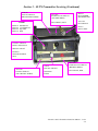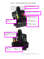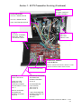
1
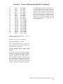
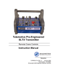
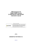
Telemotive SLTX Transmitter
Remote Crane Controls
Instruction Manual
TC18KSLTX-0 Rev. C
January 2006
Part Number: 178-01000
©Copyright 2006 Magnetek Material Handling
This page intentionally left blank.
Table of Contents
1- Service Information ....................................................................................................................... 1-1
1. Service Information ................................................................................................. 1-1
2- Radio Controlled Crane Safety...................................................................................................... 2-1
1. Warnings, Cautions And Notes ................................................................................ 2-1
2. Critical Installation Considerations.......................................................................... 2-1
3. General ..................................................................................................................... 2-2
4. Persons Authorized To Operate Radio Controlled Cranes....................................... 2-2
5. Training Checklist For Crane Operators .................................................................. 2-2
6. Operating Area ......................................................................................................... 2-3
7. Transmitter Unit ....................................................................................................... 2-3
8. Operating The Crane ................................................................................................ 2-3
9. Boarding The Crane ................................................................................................. 2-4
10. Crane Repair ............................................................................................................ 2-4
11. Using The Crane As A Work Platform .................................................................... 2-5
12. Condition Of The Radio Controlled Crane .............................................................. 2-6
13. Battery Disposal ....................................................................................................... 2-6
3- General System Information ......................................................................................................... 3-1
1. General System Information .................................................................................... 3-1
2. FCC Regulations ...................................................................................................... 3-1
3. Signaling .................................................................................................................. 3-1
4. Part 90 TMS And Continuous Carrier ..................................................................... 3-1
5. Part 15 TMS ............................................................................................................. 3-1
6. Receiver Unit ........................................................................................................... 3-1
7. Part 15 Specifications .............................................................................................. 3-1
8. Time Multiplex Shared (TMS) System Software ................................................... 3-2
4- SLTX Transmitter Operation ........................................................................................................ 4-1
1. Power On/Off Switch............................................................................................... 4-1
2. E-Stop ...................................................................................................................... 4-1
3. Motion Push Buttons, Joysticks Or Levers .............................................................. 4-1
4. Battery Monitor LED Indicator................................................................................ 4-1
5. Time-Out-Timer....................................................................................................... 4-1
6. Key Switch (For Models So Equipped) ................................................................... 4-1
7. Servicing Information .............................................................................................. 4-2
5- SLTX Transmitter Servicing ......................................................................................................... 5-1
1. SLTX Transmitter Setup Information ...................................................................... 5-1
2. Setting Access Code ................................................................................................ 5-1
3. Programming Switches ............................................................................................ 5-1
4. To Check Data ......................................................................................................... 5-3
5. Battery Monitor........................................................................................................ 5-3
6. Analog Voltage Reference ....................................................................................... 5-3
7. Transmit LED ......................................................................................................... 5-3
8. Batteries and Charger .............................................................................................. 5-3
9. Replacement Parts ................................................................................................... 5-3
Telemotive SLTX Transmitter Instruction Manual – 1/1/06
i
Section 1 – Service Information
1-1. Service Information.
Thank you for your purchase of Magnetek’s
Telemotive® brand SLTX Radio Remote
Crane Control. Magnetek has set a whole
new standard in radio-remote performance,
dependability, and value with this unique
new line of belly box transmitters. Without a
doubt, our Telemotive SLTX is the ultimate
solution for having precise, undeterred, and
safe control of your material.
If your product ever needs modification or
service, please contact one of our
representatives at the following locations:
U.S. Service Information
For questions regarding service or technical
information contact:
1-866-MAG-SERV
(1-866-624-7378).
Magnetek Material Handling
N49 W13650 Campbell Drive
Menomonee Falls, WI 53051
Telephone:
800-288-8178
Website:
e-mail:
www.magnetekmh.com
[email protected]
Fax Numbers:
Main:
800-298-3503
Sales:
262-783-3510
Service:
262-783-3508
Canada Service Information:
4090B Sladeview Crescent
Mississauga, Ontario
L5L 5Y5 Canada
Phone: 1-800-792-7253
Fax: 1-905-828-5707
Telemotive SLTX Transmitter Instruction Manual – 1/1/06
1-1
Section 2 - Radio Controlled Safety
Warnings, Cautions And Notes.
2-1. Critical Installation Considerations.
Through out this document WARNING,
CAUTION and NOTE statements have been
deliberately placed to highlight items critical to
the protection of personnel and equipment.
WARNING – A warning highlights an essential
operating or maintenance procedure, practice,
etc. which if not strictly observed, could result in
injury or death of personnel, or long term physical hazards. Warnings are highlighted as shown
below:
WARNING
ALL EQUIPMENT MUST HAVE A
MAINLINE CONTACTOR INSTALLED AND
ALL TRACKED CRANES AND SIMILAR
EQUIPMENT MUST HAVE A BRAKE INSTALLED. FAILURE TO FOLLOW THIS
WARNING COULD RESULT IN SERIOUS
INJURY OR DEATH AND DAMAGE TO
EQUIPMENT.
WARNING
CAUTION – A caution highlights an essential
operating or maintenance procedure, practice,
etc. which if not strictly observed, could result in
damage to, or destruction of equipment, or loss
of functional effectiveness. Cautions are highlighted as shown below:
CAUTION
NOTE – A note highlights an essential operating
or maintenance procedure, condition or statement. Notes are shown as below:
WARNING
ON ALL REMOTE CONTROLLED CRANES
AN AUDIBLE AND/OR VISUAL WARNING
MEANS MUST BE PROVIDED. THESE AUDIBLE AND/OR VISUAL WARNING DEVICES MUST MEET ALL GOVERNMENTAL
REQUIREMENTS. FAILURE TO FOLLOW
THIS WARNING COULD RESULT IN SERIOUS INJURY OR DEATH AND DAMAGE TO
EQUIPMENT.
NOTE
WARNINGS, CAUTIONS AND NOTES
SHOULD NEVER BE DISREGARDED.
The safety rules in this section are not intended
to replace any rules or regulations of any applicable local, state, or federal governing organizations. The following information is intended to
be used in conjunction with other rules or regulations already in existence. It is important to
read all of the safety information contained in
this section before installing or operating the
Radio Control System.
WARNING
REMOVE ALL ELECTRICAL POWER FROM
THE CRANE OR MACHINERY BEFORE ATTEMPTING ANY INSTALLATION PROCEDURES. DE-ENERGIZE AND TAG OUT ALL
SOURCES OF ELECTRICAL POWER
BEFORE TOUCH TESTING ANY EQUIPMENT. FAILURE TO FOLLOW THIS WARNING COULD RESULT IN SERIOUS INJURY
OR DEATH AND DAMAGE TO EQUIPMENT.
Telemotive SLTX Transmitter Instruction Manual – 1/1/06
2-1
Section 2 - Radio Controlled Safety (Continued)
2-4. Training Checklist For Crane Operators.
WARNING
THE DIRECT OUTPUTS OF THIS PRODUCT
ARE NOT DESIGNED TO INTERFACE DIRECTLY TO TWO STATE SAFETY CRITICAL MAINTAINED FUNCTIONS, I.E.,
MAGNETS, VACUUM LIFTS, PUMPS,
EMERGENCY EQUIPMENT, ETC. A MECHANICALLY LOCKING INTERMEDIATE
RELAY SYSTEM WITH SEPARATE POWER
CONSIDERATIONS MUST BE PROVIDED.
FAILURE TO FOLLOW THIS WARNING
COULD RESULT IN SERIOUS INJURY OR
DEATH AND DAMAGE TO EQUIPMENT.
Anyone being trained to operate a radio-controlled crane should possess as a minimum the
following knowledge and skills before operating
the crane:
The operator should have knowledge of hazards
peculiar to crane operation.
The operator should have knowledge of the
safety rules for radio-controlled cranes.
The operator should have the ability to judge
distance or moving objects.
The operator should have knowledge of the radio
transmitter.
The operator should know the limit switch test
procedure.
2-2. General.
Radio controlled overhead cranes and other material handling equipment operate in several directions. They are large, bulky pieces of equipment that handle heavy loads efficiently at high
speeds. Quite frequently, the equipment is operated in areas where people are working on the
floor below. The crane operator must exercise
extreme caution at all times. Workers must constantly be alert to avoid accidents. The following
rules have been included to indicate how your
careful and thoughtful actions may prevent injuries, damage to equipment, or even save a life. If
radio controlled material-handling equipment is
operated from the cab, special care must be taken
to secure the transmitter. Refer to section titled
Section 2-8. Boarding The Crane for specific
safety rules.
2-3. Persons Authorized To Operate Radio
Controlled Cranes.
Only properly trained persons designated by
management should be permitted to operate radio-controlled cranes.
Radio controlled cranes should not be operated
by any person who cannot read or understand
signs, notices and operating instructions that
pertain to the crane.
Radio controlled cranes should not be operated
by any person with insufficient eyesight or
hearing or by any person who may be suffering
from a disorder or illness or is taking any medication that may cause loss of crane control.
The operator should know, where authorized,
instructions for plugging motions.
The operator should have knowledge of the use
of crane warning lights and alarms.
The operator should have
observing crane signal lights.
knowledge
of
The operator should be trained to avoid striking
any obstructions.
The operator should have knowledge of the
proper clearance of lifts or hooks before moving
bridge or trolley.
The operator should have knowledge of the
proper storage space for radio control box when
not in use.
The operator should be trained in transferring
radio control box to another person.
The operator should be trained how and when to
report unsafe or unusual operating conditions.
The operator should be trained how to exhibit
caution in approaching bridge or trolley bumpers.
The operator should know equipment capacity.
The operator should be trained in making lifts
below floor level.
Telemotive SLTX Transmitter Instruction Manual – 1/1/06
2-2
Section 2 - Radio Controlled Safety (Continued)
The operator should be trained in making side
pulls.
be centered over an area free of personnel and
equipment.
The operator should know how to keep himself
and other people clear of lifts and to avoid
"pinch" points.
Visually inspect the hook, load lines, trolley, and
bridge as much as possible from the operator's
station; in most instances, this will be the floor of
the building.
The operator should know cable and hook
inspection procedures.
The operator should know procedures for testing
hoist, trolley, and bridge brakes.
2-5. Operating Area.
Aisles between equipment, stock, etc., should be
free of obstructions so the crane operator can
move freely. These aisles should be a minimum
of three feet (one meter) wide, or meet local
regulations.
Crane operators should always position themselves for the best view of the crane they are
controlling. The crane should never be operated
blindly. The operator should stay as close to the
crane load as possible. Operators should never
position themselves in a "pinch" point.
2-6. Transmitter Unit.
The bridge and trolley brakes should be tested.
On transmitter units equipped with two or more
speeds, use the "lowest" speed when testing
braking devices.
When lifting maximum loads, the crane operator
should test the hoist brakes by raising the load a
few inches from the floor. If the brakes do not
hold, the load should immediately be lowered to
the floor.
If provided, test the lower-limit switch.
Test all warning devices.
Test all direction and speed controls for both
bridge and trolley travel.
Test all bridge and trolley limit switches, where
provided, if operation will bring the equipment
in close proximity to the limit switches.
Transmitter switches should never be mechanically blocked ON or OFF for any crane motion.
When not in use turn the transmitter OFF. A secure storage space should be provided for the
transmitter unit and the transmitter unit should
always be placed there when not in use. This
precaution will prevent unauthorized people
from operating the crane.
Test the transmitter emergency stop.
Spare transmitters should be stored in a secure
storage space and only removed from the storage
space after the current transmitter in use has been
turned OFF, taken out of the service area and
secured.
2-7.2. General Rules For Operation.
2-7. Operating The Crane.
Test the hoist brake to verify there is no drift
without a load.
If any crane or hoist that fails any of the above
tests notify the supervisor and lock out and tag
for repair.
Consult the crane manufacturer, local and
governmental regulations for complete rules of
operation. In general the following rules apply to
remotely controlled cranes:
2-7.1. Pre-operation Test.
The limit switches should never be used as a
regular stopping device. They are intended to be
protective devices.
At the start of each work shift, or when a new
operator takes control of the crane, operators
shall do as a minimum the following steps before
making lifts with any crane or hoist:
Do not make lifts in excess of the equipment
rated capacity.
Test the upper-limit switch. Slowly raise the
unloaded hook block until the limit switch trips.
When checking limit switches the hoist should
The bridge and trolley should be centered directly over the load when the load is raised to
prevent swinging when making lifts.
Telemotive SLTX Transmitter Instruction Manual – 1/1/06
2-3
Section 2 - Radio Controlled Safety (Continued)
A crane designed for this purpose and only with
supervisor permission should make side pulls.
When a lift is being made, the crane operator
should not be positioned in the line of travel. The
crane or hoist should be operated from a position
either to the side or opposite from the direction
of travel.
The crane operator should never permit anyone
to ride on the load or hook except when authorized by the supervisor.
When another crane on the same runway is stationary with a load hanging, the crane operator
should maintain a safe distance between the stationary crane and the one under their control.
When raising or lowering a load, proceed slowly
and make certain the load is under control. Tag
lines should be used for handling unusual lengths
or bulky loads. Remove slack from chains or
slings gradually. Make certain all personnel are
clear before making a lift.
Never leave suspended loads unattended. In an
emergency, if the crane is inoperative and a load
suspended, notify the supervisor immediately,
barricade and post signs on the floor beneath
crane and load.
The crane operator should keep all body parts
away from the lift and should never be positioned under the lift.
If power to the crane is removed, the crane operator should turn the transmitter unit OFF and
keep it OFF until power is restored.
Do not make a lift or move a load if anyone is in
a location where they could be struck by the
crane or the load.
If the crane fails to respond properly, the crane
operator should stop operation, turn the transmitter unit OFF and immediately report the condition to their supervisor.
If the crane operator is being helped, the crane
should not be moved until the helper signals they
are clear of the crane and its load.
When a load is hanging from the crane hook and
the crane is being moved, the crane operator
should sound all warning devices frequently.
Loads should not be carried over workers heads.
If a worker is in the path of crane travel, the
crane operator should stop the crane and clear
the area before proceeding.
Runway stops or other cranes should never be
bumped into.
When moving the crane, the crane operator
should be sure that the hook block and attachments or cables would not catch on nearby
equipment. Slings, chains, or cables should never
be dragged along the floor.
Unless required for operator safety, gloves
should not be worn when operating the transmitter unit.
All loose materials or parts should be removed
from the load before starting the lift.
The crane operator should always hoist lifts high
enough to clear all equipment and workers.
Outdoor cranes, which are subject to movement
by wind, should be securely anchored when left
unattended. If the crane is equipped with bridge
brakes, the parking brake should be set immediately.
2-8. Boarding The Crane.
The crane should not be boarded without permission of the supervisor.
The crane operator should turn off the transmitter
and take it with them when boarding the crane.
If more than one person is boarding the crane,
one person should be made responsible for ensuring all personnel are off the crane before the
system is returned to operation.
2-9. Crane Maintenance And Repair.
Qualified personnel must maintain a regularly,
i.e., such as monthly, scheduled crane inspection.
During this crane inspection the functionality
and safety of the crane remote control must also
be tested. The inspection shall include, but be not
limited to items listed in Section 2-11. Condition
Of The Radio Controlled Crane. Consult crane
manufacturer, local and governmental regulations for recommended inspection intervals and
proper inspection procedures. Problems noted
during this inspection must be repaired before
using the crane or the remote control.
Telemotive SLTX Transmitter Instruction Manual – 1/1/06
2-4
Section 2 - Radio Controlled Safety (Continued)
Minor repairs include routine maintenance and
repairs such as greasing, cleaning and control
troubleshooting. All other repairs should be considered major. If the repair crew consists of more
than one person, one person should be designated as the repair crew leader with the following responsibilities. If the repair crew consists of
only one person, that person has the following
responsibilities:
For minor repairs warning signs should be
placed on the floor beneath the crane or suspended from the crane. For major repairs, the
floor area below the crane should be roped off.
When major repairs are to take place, all persons
operating other cranes on the same or adjacent
runways, if any, must be notified prior to starting
repairs. Notification should include the nature of
the repair, safeguards provided, and movement
limitations while repairs are in progress.
When practical, radio controlled cranes which
cannot be moved during repairs must be protected against being bumped by other cranes on
the runway. Bumpers should be installed on the
exposed side or sides of the crane under repair.
They should be placed as far away as possible.
The location of these bumpers should be indicated by red lights placed so that they are clearly
visible to other crane operators traveling on the
same runway. When it is not possible to use
bumpers, red lights must be placed so they are
clearly visible to other crane operators traveling
on the same runway to indicate the restricted
travel zone. All crane operators on the same
runway must be informed of the repair effort and
thoroughly instructed to what their operations are
limited to and informed they will be notified
when repairs are completed.
If any hazard involving the repairmen exists
when there is a runway adjacent to the crane under repair, the adjacent runway should be
blocked off as described above. When it is necessary to continue crane operation on the adjacent runways warning lights must be installed
and be visible to operators of cranes on those
runways. All cranes should come to a complete
stop prior to entering the restricted area and
should proceed through this area only after receiving permission from a signal person designated for this purpose. Access of persons to and
from the crane being repaired should be under
control of the repair crew leader.
When boarding the crane, the transmitter should
be turned OFF and the transmitter should remain
with the repair crew leader. The leader should
board the crane first, open and lock out the main
switch, and then signal the other members of the
crew it is safe to board the crane.
If work on the crane is to be done in areas not
protected by standard handrails, the repair crew
should wear approved safety belts.
All tools and equipment should be moved onto
the crane by the use of hand lines. The tools and
equipment should be adequately secured to the
hand lines.
If it is necessary to have the crane control circuits energized, all power circuits for crane
movement must be opened prior to energizing
the control circuits.
All personnel and tools should be moved to a
safe spot before moving the crane during repairs.
Headroom is at a minimum in some crane cabs
and on some crane walkways. Caution should be
exercised when boarding or working on cranes.
Hard hats should be worn whenever possible.
When repairs are finished, all personnel, tools
and repair equipment should be removed before
energizing the crane circuits.
2-10. Using The Crane As A Work Platform.
When the crane is to be used as a stationary work
platform, follow all rules provided in Section 29. Crane Maintenance and Repair. When it is
necessary for the crane to be moved from time to
time, the crane operator should board the crane
with the transmitter unit. The crane operator
should ensure all personnel working on the crane
are in a secure position before moving the crane
to the next workstation. It should also be the
crane operator’s responsibility to ensure the main
switch is open and locked down before work is
resumed.
Telemotive SLTX Transmitter Instruction Manual – 1/1/06
2-5
Section 2 - Radio Controlled Safety (Continued)
Protective guards are in place for all moving
parts.
WARNING
Alignment of bridge (screeching or squealing
wheels indicate bridge is out of line).
THE CRANE OPERATOR SHOULD NOT ATTEMPT TO REPAIR ANY OF THE ITEMS
STATED BELOW. THE CRANE CONDITION
SHOULD BE REPORTED TO THE SUPERVISOR. FAILURE TO FOLLOW THIS WARNING COULD RESULT IN SERIOUS INJURY
OR DEATH AND DAMAGE TO EQUIPMENT.
2-11. Condition Of The Radio Controlled
Crane.
If the crane fails to respond properly, the crane
operator(s) should notify their supervisor. When
serious conditions are noticed (conditions that
make the crane unsafe to operate), the crane
should be shut down immediately and the supervisor notified. The following is a list of some of
the items that should be included in the report.
(See the crane manufacturer for specifics and
possible additional items):
Condition of hoisting cable and hook block (broken strands, clipped sheave wheels, etc.).
Condition of brakes (hoist, trolley, and bridge).
(No bluing, rivets on shoes showing, glazing,
etc.).
Condition of trolley and rail stops.
Broken, cracked, or chipped rails on trolley or
runway.
Condition of limit switches.
Condition of electrical and mechanical control
(electrical or mechanical defects which cause
faulty operation such as un-commanded stopping
or starting of any crane motions, warning devices, lights, or auxiliary functions).
Condition of gears (grinding or squealing may
indicate foreign materials in gear teeth or a lack
of lubrication.
All controls especially E-STOPs are in place and
in working order.
Frequent relay tripping of power circuits.
Mechanical parts loosened by vibration (loose
rivets, covers, bolts, etc.).
Uneven riding (worn or damaged wheels).
Condition of collector shoes or bars.
Condition of warning or signal lights and horns.
(Burned out or broken).
2-12. Batteries
Condition of bridge structure.
Condition of festoon system.
WARNING
Broken welds in any part of the crane structure.
Proper fluid levels and lubrication.
Condition of bridge and trolley stops.
Carbon dust or signs burning on the covers of
motors.
Indication of fluid, oil or grease leaks.
Condition of rail sweeps.
KNOW AND FOLLOW PROPER BATTERY
HANDLING, CHARGING AND DISPOSAL
PROCEDURES. IMPROPER BATTERY PROCEDURES CAN CAUSE BATTERIES TO
EXPLODE OR DO OTHER SERIOUS DAMAGE. FAILURE TO FOLLOW THIS WARNING COULD RESULT IN SERIOUS INJURY
OR DEATH AND DAMAGE TO EQUIPMENT.
Walkways required handrails and ladders are in
place, sturdy and not loose.
Telemotive SLTX Transmitter Instruction Manual – 1/1/06
2-6
Section 2 - Radio Controlled Safety (Continued)
2-12.1. Battery Handling.
Use only batteries approved by Telemotive for
the specific product.
Do not dispose of a battery pack in fire; it may
explode.
Do not attempt to open the battery pack.
Do not short circuit battery.
For intrinsically safe environments only use
specified Telemotive intrinsically safe batteries.
Keep the battery pack environment cool during
charging operation and storage, (i.e., not in direct
sunlight or close to a heating source).
2-12.2. Battery Charging.
For those transmitters equipped with battery
chargers, please familiarize all users with the
instructions of the charger before attempting to
use.
Use only Telemotive approved chargers for the
appropriate battery pack.
Do not attempt to charge non-rechargeable battery packs.
Avoid charging the battery pack for more than
24 hours.
Do not charge batteries in a hazardous environment.
Do not short charger.
Do not attempt to charge a damaged battery.
Do not attempt to use a battery that is leaking,
swollen or corroded.
Charger units are not intended for outdoor use.
Use only indoors.
2-12.3. Battery Disposal.
Before disposing of batteries consult local and
governmental regulatory requirements for proper
disposal procedures.
Telemotive SLTX Transmitter Instruction Manual – 1/1/06
2-7
Section 3 – General System Information
3-1. General System Information.
The 10K and 18K SLTX transmitter (system)
provides remote control of overhead cranes using
radio signals. The system consists of a hand held
portable battery operated transmitter unit and a
fixed station receiver unit.
Each system has its own access code, which
permits a receiver unit to respond only to a
transmitter unit with the same access code. Up to
four transmitters may be used with the same
frequency. Each transmitter operating on the
same frequency may be operated in close
proximity (not less than six feet) to each other.
Access Code: Any received signal, which does
not match the receiver access code, is considered
invalid by the receiver.
NOTE
DETERMINE IF YOUR SYSTEM IS FCC
PART 15 OR PART 90. IF THE RECEIVER
HAS THE PART NUMBER 18087 ON THE
DOOR OR YOUR TRANSMITTER HAS A
PUSH BUTTON FOR ON/OFF RATHER
THAN A TOGGLE SWITCH IT IS FCC PART
15.
3-2. FCC Regulations.
There are two types of radio-controlled systems.
One is high power licensed (FCC Part 90) and
low power unlicensed (FCC Part 15). Both give
more than adequate range, security and features;
however there are subtle differences in operation
required by FCC rules and regulations. It is
helpful to know with system type you have to
troubleshooting and servicing.
3-3. Signaling (TMS and Continuous).
TMS (Time Multiplexed Signaling) is a
Telemotive proprietary high-speed packet data
system that transmits data in pulses. Continuous
Carrier signaling means the transmitter is
continuously transmitting power whether or not a
lever or function is activated. Continuous carrier
systems tend to be older systems.
3-4. Part 90 (TMS And Continuous Carrier).
For 18K licensed systems, the transmitter unit is
frequency modulated, has relatively high power
(greater than 100 mW typically) and a license is
required under Part 90 of FCC rules and
regulations. The transmitter unit uses crystalcontrolled oscillators to set the operating
frequency.
3-5. Part 15 (TMS only).
For 10K and 18K systems with part 15 signaling,
the transmitter unit is frequency modulated,
lower power and is certified under part 15 of
FCC rules and regulations. A license is not
required for the transmitter or operator. The
transmitter unit uses crystal-controlled oscillators
to set the operating frequency.
A power down feature turns the transmitter unit
OFF if no keys are pressed for an extended
(approximately 15 minutes) period of time. The
transmitter unit must again be turned ON. A
configuration of the transmitter unit is available
without automatic timeout.
A LED mounted on the front panel provides
battery voltage and data transmission status.
3-6. Receiver Unit.
The receiver unit consists of an RF receiver
module, microprocessor control module, output
relay/control modules and a power supply.
A power down feature turns the receiver unit
OFF if no commands are received for an
extended (approximately 15 minutes) period of
time. A configuration of the receiver unit is
available without automatic time out.
3-7. Part 15 System Specifications.
Channel Designations: (The channels listed here
are for reference purposes and are not an
indication of production stock. Some channels
may take extended delivery. Contact Telemotive
for availability).
01.
02.
03.
04.
05.
06.
07.
08.
09.
10.
11.
AK01
AK02
AK03
AK04
AK05
AK06
AK07
AK08
AK09
AK10
AK11
439.8 MHz
439.6 MHz
439.4 MHz
439.2 MHz
439.0 MHz
438.8 MHz
438.6 MHz
438.4 MHz
438.2 MHz
438.0 MHz
437.8 MHz
Telemotive SLTX Transmitter Instruction Manual – 1/1/06
3-1
Section 3 – General System Information (Continued)
12.
13.
14.
15.
16.
17.
18.
19.
20.
21.
22.
23.
24.
25.
26.
27.
28.
29.
30.
31.
AK12
AK13
AK14
AK15
AK16
AK17
AK18
AK19
AK20
AKA00
AKA01
AKA02
AKA03
AKA04
AKA05
AKA06
AKA07
AKA08
AK38
AK50
sent, and the data rate (baud). Once the packet is
sent, the transmitter will turn OFF. This allows
for other transmitters to time-share the same
frequency when a transmitter has turned OFF.
The TMS system software determines the OFF
period and repetition rate of the ON period. This
allows up to 4 transmitters to share and have
equal access to the same frequency, and also
allows for reduced battery consumption and
extended battery life.
437.6 MHz
437.4 MHz
437.2 MHz
437.0 MHz
436.8 MHz
436.6 MHz
436.4 MHz
436.2 MHz
436.0 MHz
433.125 MHz
433.325 MHz
433.525 MHz
433.725 MHz
433.925 MHz
434.125 MHz
434.325 MHz
434.525 MHz
434.725 MHz
432.4 MHz
430.0 MHz
Ambient Operating Conditions - -22°F to
+158°F (-30°C to +70°C).
Humidity - up to 95% (non-condensing).
Typical Operating Range - 300 feet.
Up to four transmitter units may operate on the
same frequency while in close proximity (not
less than six feet) to each other.
3-8. Time Multiplex Shared (TMS) System
Software.
The system software is structured to minimize
"on the air" transmission time of any transmitter.
This allows for multiple transmitters to share a
common frequency. The TMS system is
designed so that a transmitter will send a signal
for a predetermined ON time, and then will turn
OFF. The length of transmitter ON time is
referred to as data burst or packet. The packet
length is a function of the quantity of data to be
Telemotive SLTX Transmitter Instruction Manual – 1/1/06
3-2
Section 4 –SLTX Transmitter Operation
activated). If the battery goes below a safe level
the LED will not light, replace battery soon.
4-5. Time-Out-Timer.
CAUTION
BEFORE OPERATING THE TRANSMITTER
FAMILIARIZE YOURSELF WITH ALL
SAFETY INFORMATION IN THIS MANUAL
AND ANY OTHER LOCAL, STATE, OR
FEDERAL RULES OR REGULATIONS
ALREADY IN EXISTENCE. FAILURE TO
FOLLOW COULD RESULT IN DAMAGE TO,
OR DESTRUCTION OF EQUIPMENT, OR
LOSS OF FUNCTIONAL EFFECTIVENESS.
4-1. Power
“ON-OFF”
Switch
(Turns
transmitter and receiver ON and OFF).
With the key switch engaged pressing the
ON/OFF push-button switch (Part 15) or
toggling the ON/OFF toggle switch (Part 90)
turns the transmitter and then pushing the
START button turns the receiver ON. If the
transmitter is ON the BATT MONITOR light is
ON or flashing. Pushing the ON/OFF button
(Part 15) or resetting the toggle switch to OFF
(Part 90) will turn the transmitter and receiver
OFF.
4-2. E-STOP (For Emergency Stopping only).
When depressed the MCR relay is opened, the
receiver shutdown and power to the equipment is
immediately stopped. The transmitter must be
turned OFF and ON again to restore normal
operation. To be used for emergency stopping
only, not for normal system shut down. The ESTOP will not function with the optional key
switch turned OFF.
Unless this function is disabled the transmitter
will turn itself OFF if not used for 15 minutes.
4-6. Key Switch. (For Models So Equipped,
disables power to transmitter circuitry only).
For models so equipped, turning the key OFF
and removing it will disable the transmitter.
Turning the key switch to ON enables power to
the transmitter unit, but does not activate the
transmitter controls or turn ON the receiver. The
ON/OFF push button must be pushed to turn the
transmitter and receiver ON or OFF. Under
normal procedures it is recommended that the
unit be turned OFF with the ON/OFF push
button before turning OFF the key switch. On a
Part 15 unit, if the key switch is turned OFF with
the transmitter and receiver on, the key switch
must be turned ON again to use the ON/OFF
pushbutton or E-STOP. On a Part 90 system the
receiver will turn off with the key switch.
NOTE
THE KEY IS TO BE USED FOR RENDERING
THE TRANSMITTER DISABLED ONLY; IT
DOES CONTROL THE RECEIVER OR
POWER TO OR FROM THE RECEIVER.
4-3. Motion Push Buttons or Levers.
To activate motor functions, press and hold the
push-button or lever that corresponds to the
desired motion. To activate higher speed
functions for those models so equipped press the
motion switch or lever a little farther.
4-4. Battery Monitor LED Indicator.
The battery Monitor LED (red) indicates the
transmitter is on, or transmitting, or has a low
battery voltage. A slow flash rate indicates the
unit is ON. A rapid flash rate indicates a unit is
transmitting (when a function or control is
Telemotive SLTX Transmitter Instruction Manual – 1/1/06
4-1
Section 4 – SLTX Transmitter Operation (Continued)
4-7. Servicing Information.
CAUTION
FOR PRODUCT MODELS LISTED IN COMPLIANCE WITH UL, CSA AND ANSI INTRINSICALLY SAFE STANDARDS, DO NOT
ATTEMPT TO REPAIR WITHOUT USING
TELEMOTIVE APPROVED REPLACEMENT
PARTS. FAILURE TO DO SO COULD VOID
LISTING AND CREATE A SAFETY HAZARD. FOR INTRINSICALLY SAFE PRODUCTS ONLY QUALIFIED TRAINED SERVICE PERSONNEL ARE ALLOWED TO
PERFORM REPAIRS. FAILURE TO USE APPROVED SERVICING TECHNIQUES AS
WELL AS TELEMOTIVE APPROVED PARTS
FOR INTRINSICALLY SAFE PRODUCTS
COULD CREATE A SAFETY HAZARD. IF
THERE IS ANY QUESTION AS TO WHOM
IS QUALIFIED, WHAT PARTS TO USE OR
PROPER SERVICE PROCEDURES PLEASE
CONTACT
YOUR
TELEMOTIVE
REPRESENTATIVE.
CAUTION
DO NOT ATTEMPT TO OPEN OR SERVICE
THE SLTX UNIT. ONLY TRAINED
QUALIFIED INDIVIDUALS SHOULD DO
SERVICING.
STRICT
ANTI-STATIC
HANDLING PROCEDURES MUST BE
FOLLOWED. FAILURE TO FOLLOW THIS
CAUTION COULD RESULT IN SERIOUS
DAMAGE TO EQUIPMENT AND/OR VOID
THE WARRANTY.
Telemotive SLTX Transmitter Instruction Manual – 1/1/06
4-2
Section 5 – SLTX Transmitter Servicing (Continued)
5-1. SLTX Transmitter Board Setup
Information.
The SLTX Transmitter Board is shown in Figure
5-1. Refer to paragraphs 5-1 through 5-10 for
servicing procedures.
M5
J29
J32
J28
J31
M4
J27
J30
J34 J33
J17 J35
M3
J21
M6
J36 J38
J3
J2
J37
8
7
6
AUX B
5
M7
J6
TP5
POWER
CONTROL
J9
J20 Power
connector
J8
Battery
1
OFF
M1
OFF
OFF
J23
EXTERNAL CODE PLUG
EPROM
TP4 +5V
TP3 DATA
AND
2
J5
8---------1 8---------1 8---------1 8---------1
SW2 “B” SW1 “A” SW4 “D” SW3 “C”
TP2
GND
Figure 5-1. 10K
4 3
AUX A
OFF
RF
MODULE
E13653-X
J7
J19 J18 J14 J13 J12 J11 J10
16 15 14 13 12 11 10 9
ANT.
J4
M2
E10642
18K SLTX
J1
J24
ON/OFF LED
Key switch
J15
ON/OFF switch
J25
EMS (ESTOP)
J26
Not used
RPOT1
J9 Firmware Loading
Connector
TP6
J40
Firmware
Number Label
Reset
RPOT2
J39
TP1
Transmitter Board
then B1 through B4. For 8 bit access codes
switch B is not used.
5-2. SLTX Programming Switches.
The programming switch SW3 controls the
following features: (These only apply to units
originally programmed to utilize these features).
External Code Plug Enable – Switch SW3position 1 turn “ON” to enable external code
plug.
Time-Out-Timer Disable – Switch SW3-position
8 turn “ON” to disable transmitter time-out
timer.
5-3. Access Codes Switches. (SW1 and SW2).
Setting Access Code (for units with no
external code plug only).
For Part 90 systems the 12 bit access code is
assigned starting with position A1 through A8
The access code is set at the factory and should
not be changed unless absolutely necessary. If a
spare transmitter unit is used, the receiver unit
access code should be changed to match the
access code of the spare transmitter unit. For Part
15 systems the access codes are printed on a
white label on the outside of any transmitter and
may be matched to “A” and “B” on the receiver
CPU Board without having to open the
transmitter housing.
Switch SW2 (B) in the transmitter must match
switch (B) on the receiver CPU Board and
switch SW1 (A) in the transmitter must match
switch (A) on the receiver CPU Board.
If the codes do not match you will get an error
light DS9 on the receiver CPU Board while
transmitting.
Telemotive SLTX Transmitter Instruction Manual – 1/1/06
5-1
Section 5 – SLTX Transmitter Servicing (Continued)
If you are reprogramming a spare transmitter
make sure the other transmitter is securely taken
out of service.
5-3.2.1.1.
“OFF”).
5-3.2.1.2.
Position 8 Time-out-timer
Disable. (Normally keep turned “OFF”).
WARNING
TWO OPERATIONAL TRANSMITTERS
WITH THE SAME ACCESS CODES OPERATING AT THE SAME TIME IS A DEFINITE
SAFETY HAZARD. FAILURE TO FOLLOW
THIS WARNING COULD RESULT IN SERIOUS INJURY OR DEATH AND DAMAGE TO
EQUIPMENT.
Telemotive receivers are shipped with the access
code settings for the transmitter marked on the
receiver door.
Also a label on the transmitter lists the access
code settings inside. The positions on the
transmitter label match the switch settings. The
“1” by A1 means the switch position A1 should
be ”ON” and “0” means A1 should be “OFF”.
5-3.1.1. Changing Transmitter Access
Codes.
WARNING
AFTER CHANGING THE ACCESS CODES
ON THE TRANSMITTER, TEST THE UNIT
BY TURNING IT ON AND OFF NEAR THE
APPROPRIATE RECEIVER. IF THE RECEIVER DOES NOT RESPOND, DO NOT
ACTIVATE A FUNCTION BUTTON! THE
TRANSMITTER MAY HAVE THE WRONG
ACCESS CODE, WHICH COULD MOVE
ANOTHER CRANE. RE-CHECK THE
ACCESS CODE IN THE TRANSMITTER
AND RETEST. FAILURE TO FOLLOW THIS
WARNING COULD RESULT IN SERIOUS
INJURY OR DEATH AND DAMAGE TO
EQUIPMENT.
5-3.2. 10K Series SLTX Programming
Switches SW3 and SW4 Programming.
5-3.2.1. Transmitter programming SW3.
Positions 1-7 (Keep turned
The transmitter has an approximate 15-minute
time-out-timer. If the transmitter is not used for
over 15 minutes it will shut down. This
transmitter time-out-timer function is transmitter
dip switch selectable. SW3 position 8 disables
the time-out-timer.
Turning SW3-8 “ON”
disables the time-out-timer.
5-3.2.2. Transmitter programming SW4.
5-3.2.2.1.
Position 1-2 Mode Enable.
(Standard Mode 1, keep 1-2 turned “OFF”).
Mode 1, SW4 1-2 all “OFF”. The 10K12 single
speed system comes standard configured this
way from the factory with three motion controls
and six auxiliaries (controlled by the toggle
switches). The 10K12 2-speed system comes
standard configured this way from the factory
with three 2-speed controls and three auxiliaries
(controlled by the toggle switches, the rotary is
non-functional).
Mode 2, SW4 1 turned “OFF” and SW4 2 turned
“ON”. The 10K12 2-speed system configured
this way is able to control four 2-speed motion
controls and no auxiliaries this give bridge,
trolley, main and aux hoist. The rotary selector
switch functions are H1 main hoist, H2 aux hoist
and B both main and aux hoist (the toggle
switches are non-functional).
Mode 3, SW4 1 and 2 turned “ON”. The 10K12
2-speed system will control up to 5 motors using
the rotary selector switch.
This mode
reconfigures two of the 10K12 auxiliary outputs
(Aux 1 and Aux 2) to be external motor select
functions by the rotary switch. In this mode the
auxiliary toggle switch Aux 1 and Aux 2 is
disabled. When the rotary switch is in the H1 or
H2 position Aux 1 relay or Aux 2 relay will pull
in respectively when ever trolley or hoist
pushbuttons are pressed. When the rotary switch
is in B position both Aux 1 and Aux 2 relays will
pull in.
5-3.2.2.2.
Position 3 Disable Tandem for
Hoist and Trolley. (Normally keep turned
“OFF”).
Telemotive SLTX Transmitter Instruction Manual – 1/1/06
5-2
Section 5 – SLTX Transmitter Servicing (Continued)
For cranes with auxiliary hoists and/or trolleys,
turning this switch “ON”
disables the
transmitter selector switch “B” position (both
function) that selects tandem operation of hoist
or trolley.
2). Use RF SW pin on RF Module for External
Trigger input.
3). Use TP2 for Ground.
5-5. Battery Monitor.
5-3.2.2.3.
Position 4 Invert Crane Select
Aux. Outputs. (Normally keep turned
“OFF”).
Set to 5.8 Volts by R6 and R8 not adjustable.
For cranes that use the select function only,
turning this switch “ON” inverts the select
function operation so that the relay closes for
the unselected function.
Controls lever range, V+ (TP1) factory adjusted
with RPOT2 (zero adjust) V- (TP6) factory
adjusted with RPOT1 (full scale adjust).
5-6. Analog Voltage Reference.
5-7. Transmit LED.
5-3.2.2.4.
Positions 5-7 Extended Crane
Control Configurations. (Standard all
“OFF” otherwise see the appropriate
receiver manual).
This flashing red LED flashes rapidly during
transmit, slowly when unit is ON and turns out
when battery is low.
The 10K12/18 SLTX transmitter is available
with extended crane control configurations.
These options are switch configurable on the
transmitter. The eight-position dip switches
SW3 and SW4 on the transmitter can provide all
configurations with a single transmitter CPU
EPROM for the 2-speed transmitter. See your
receiver manual for available configurations and
the switch programming needed to provide them.
5-3.2.2.5.
Position 8 No Function (keep
turned off).
5-4. To Check Data.
1). For data input use Data pin on RF Module.
5-8. Batteries and Charger.
Two batteries are available, a disposable alkaline
battery BT10KP-0 and a rechargeable NiCad
BT10KP-1. The single unit charger for the
BT10KP-1 is E10670-1. The typical recharge
time for a completely discharged battery is
approximately three hours. Please follow local
regulations for the disposal of any battery
product.
5-9. Replacement Parts.
The following pictures detail replacement parts
for the SLTX:
Telemotive SLTX Transmitter Instruction Manual – 1/1/06
5-3
Section 5 – SLTX Transmitter Servicing (Continued)
A232-201
TOGGLE SWITCH
(BRN/RED/ORN WIRES)
KNOBS
MP681-0
MP630-0
MP632-0
MP633-0
A233-202
PUSH BUTTON SWITCH
(YEL/ORN WIRES)
MP135-1
KEY, RUBBER
MOLDED KNOB
H634-0 BOOT, GREY
A231-204
KEY SWITCH
SPHERICAL
CYLINDRICAL
SQUARE
HEX
H634-0
BOOT, GREY
TOGGLE SWITCH
BOOTS AND SEALS
MP10661-0 BOOT
H10008-0
SWITCH BUSHING
SEAL
A232-200
TOGGLE SWITCH
(YEL/GRN/BLU WIRES)
A235-0
ROTARY SWITCH
MP10604-0
KNOB
A233-201
PUSH BUTTON SWITCH
(BRN/RED WIRES)
H635-0 BOOT, RED
Telemotive SLTX Transmitter Instruction Manual – 1/1/06
5-4
Section 5 – SLTX Transmitter Servicing (Continued)
A1444-9 10K METAL HANDLE
H1954-1 SCREW 6-32 X 1 METAL HANDLE
2 PLACES EACH
A2261-111
10K END CAP ASSEMBLY
UHF ANTENNA UNLICENSED
METAL HOUSING H1019-0
SCREW 6-32 X 3/4
(4 PLACES)
A2261-100
18K END CAP ASSEMBLY
VHF ANTENNA LICENSED
A2261-110
18K END CAP ASSEMBLY
UHF ANTENNA LICENSED
METAL HOUSING
A2260-100 END CAP ASSEMBLY
BATTERY, INCLUDES CAPTIVE
SCREWS
METAL HOUSING
H732-1
CAPTIVE SCREW
(5 PLACES)
H1225-0
SCREW RETAINER
(5 PLACES)
Telemotive SLTX Transmitter Instruction Manual – 1/1/06
5-5
Section 5 – SLTX Transmitter Servicing (Continued)
A10686-2
BATTERY CONTACT
BOARD ASSEMBLY
LEVER SWITCHES
S764-101 3 SPEED SWITCH
S763-101 5 SPEED SWITCH
S1005-100 STEPLESS SWITCH
A2160-0
HOUSING ASSEMBLY,
BOTTOM – METAL
10K MODELS ONLY
MP1325-0
BRACKET
METAL CASE
E10642-0 CPU MODULE
(LESS RF HEAD)
Must be ordered with Firmware number. For 10K
check for Firmware number label on board.
Firmware number label
E13653-X
PART 15 RF HEAD
-X EQUALS THE
FREQUENCY OR
CHANNEL NUMBER
FOR EXAMPLE IF AK05
USE –5
PART 90 LICENSED
TRANSMITTER
INTERFACE BOARD
E13655-X
FOR PART 90 LICENSED
TRANSMITTER
INTERFACE BOARD
E13655-X
RF TRANSMITTER
(NOT SHOWN):
VHF E7650-X
UHF E7651-X
CABLE TRANSMITTER
INTERFACE BOARD TO
TRANSMITTER
WA1007-3
Telemotive SLTX Transmitter Instruction Manual – 1/1/06
5-6
Section 5 – SLTX Transmitter Servicing (Continued)
This page intentionally left blank.
Telemotive SLTX Transmitter Instruction Manual – 1/1/06
5-7