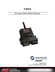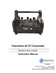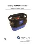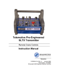
1
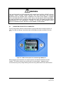
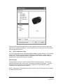
Enrange XLTX Transmitter Wireless Controls April 2011 Part Number: 178-01598-1000-R3 ©Copyright 2011 Magnetek Material Handling Your New Radio Remote Thank you for your purchase of Magnetek’s Enrange® brand XLTX Radio Wireless Controls. Magnetek has set a whole new standard in radio-remote performance, dependability, and value with this unique new line of bellybox transmitters. If your product ever needs modification or service, please contact one of our representatives at the following locations: U.S. Service Information For questions regarding service or technical information contact: 1.866.MAG.SERV (1.866.624.7378). Magnetek, Inc. N49 W13650 Campbell Drive Menomonee Falls, WI 53051 Telephone: 1.800.288.8178 Website: e-mail: www.magnetekmobilehydraulic.com [email protected] Fax Numbers: Main: 1.800.298.3503 Sales: 1.262.783.3510 Service: 1.262.783.3508 Canada Service Information: 4090B Sladeview Crescent Mississauga, Ontario L5L 5Y5 Canada Phone: 1.800.792.7253 Fax: 1.905.828.5707 1.416.424.7617 (24/7 Service pager) ©2011 MAGNETEK All rights reserved. This notice applies to all copyrighted materials included with this product, including, but not limited to, this manual and software embodied within the product. This manual is intended for the sole use of the person(s) to whom it was provided, and any unauthorized distribution of the manual or dispersal of its contents is strictly forbidden. This manual may not be reproduced in whole or in part by any means whatsoever without the expressed written permission of MAGNETEK. Enrange Engineered XLTX Transmitter Instruction Manual April 2011 Page 2 of 40 TABLE OF CONTENTS 1.0 INTRODUCTION .................................................................................................................. 5 1.1 PRODUCT MANUAL SAFETY INFORMATION ............................................................... 5 1.2 WARNINGS and CAUTIONS ............................................................................................ 6 2.0 CRITICAL INSTALLATION CONSIDERATIONS ................................................................. 7 2.1 GENERAL ......................................................................................................................... 7 2.2 PERSONS AUTHORIZED TO OPERATE RADIO CONTROLLED EQUIPMENT ........... 7 2.3 SAFETY INFORMATION AND RECOMMENDED TRAINING FOR RADIO CONTROLLED EQUIPMENT OPERATORS .............................................................................. 8 2.4 TRANSMITTER UNIT ....................................................................................................... 9 2.5 PRE-OPERATION TEST .................................................................................................. 9 2.6 HANDLING BATTERIES................................................................................................. 10 2.7 OPTIONAL RECHARGABLE BATTERY CHARGING ................................................... 10 2.8 BATTERY DISPOSAL..................................................................................................... 10 3.0 XLTX TRANSMITTER STANDARD CONFIGURATION AND OPERATION ..................... 11 3.1 INSTALLING BATTERY PACK(S) .................................................................................. 12 3.1.1 Alkaline Battery Pack (BT129) ................................................................................. 12 3.1.2 Optional NiMH Rechargeable Battery Pack (BT128) .............................................. 13 3.1.3 Spare Battery Storage Compartment ...................................................................... 14 3.1.4 Setting Battery Type Dip Switches .......................................................................... 14 3.2 TURNING THE TRANSMITTER ON AND OFF.............................................................. 15 3.2.1 Turning On the Transmitter ...................................................................................... 16 3.2.2 Pulling In the Machine Stop Relay ........................................................................... 16 3.2.3 Turning Off the Transmitter ...................................................................................... 16 3.3 MACHINE STOP SWITCH (For Emergency Stopping Only) .......................................... 16 3.4 GRAPHIC USER INTERFACE ...................................................................................... 16 3.5 NORMAL OPERATING MODE ....................................................................................... 17 3.5.1 Watch Dog Indicator (Spinning Arrow) .................................................................... 17 3.5.2 Command Confirmation ........................................................................................... 17 3.5.3 Battery Life Indicator ................................................................................................ 17 3.5.4 Signal Strength Indicator ......................................................................................... 18 3.5.5 Two-Way Feedback System .................................................................................... 18 3.6 JOYSTICKS AND PADDLES/LEVERS .......................................................................... 18 3.7 ROTARY SELECTOR SWITCH ..................................................................................... 18 3.8 AUXILIARY SWITCHES ................................................................................................. 18 4.0 USING THE TRANSMITTER IN SETUP MODE ................................................................ 19 4.1 ENTERING SETUP MODE ............................................................................................. 19 4.2 ADJUSTING SETTINGS IN SETUP MODE ................................................................... 19 4.2.1 Access Code ............................................................................................................ 19 4.2.2 Channel Select......................................................................................................... 19 4.2.3 User Code ................................................................................................................ 20 4.2.4 Transmitter Timeout ................................................................................................. 20 4.2.5 Backlight Timeout .................................................................................................... 20 4.2.6 Password Enable ..................................................................................................... 20 4.2.7 Change Password.................................................................................................... 21 4.2.8 Exit Without Save..................................................................................................... 21 4.2.9 Exit With Save.......................................................................................................... 21 5.0 OPTIONAL PROGRAMMING WITH RCP.......................................................................... 22 5.1 ACCESS CODES............................................................................................................ 22 5.2 CHANGING RECIEVER ACCESS CODES.................................................................... 22 5.3 CONNECTING THE XLTX TO A COMPUTER............................................................... 23 5.4 PROGRAMMING WITH RCP ......................................................................................... 24 5.4.1 XLTX Configuration Pages ...................................................................................... 26 5.4.2 Saving, Downloading, and Reading the Programs and Other RCP Software Functions ................................................................................................................................ 31 Enrange Engineered XLTX Transmitter Instruction Manual April 2011 Page 3 of 40 6.0 TRANSMITTER CHANNEL CONFIGURATION SETTINGS ............................................. 33 6.1 FCC STATEMENTS....................................................................................................... 33 6.2 CHANNEL AND FREQUENCY DESIGNATIONS BY COUNT....................................... 34 6.3 OPTIONAL FREQUENCIES AND CHANNELS ............................................................. 35 6.3.1 900 MHz: FHSS ....................................................................................................... 35 6.3.2 2.4 GHz: FHSS ........................................................................................................ 35 6.3.3 433 MHz Telemotive Legacy Channel Set: TMS and TDMA .................................. 35 7.0 OPTIONAL CAN BUS TETHER FEATURE ....................................................................... 36 7.1 INSTALLATION OF TETHER CABLE......................................................................... 36 7.2 OPERATION OF TRANSMITTER IN TETHER MODE ............................................... 36 7.3 RETURNING TRANSMITTER TO WIRELESS MODE ............................................... 36 7.4 CAN CONNECTOR RECEPTACLE PIN-OUT DETAILS ............................................ 37 8.0 GENERAL TROUBLESHOOTING .................................................................................... 38 8.1 TROUBLESHOOTING: OPTIONAL TETHER OPERATION .......................................... 39 8.2 ASSEMBLY AND REPLACEMENT PARTS ................................................................... 40 Enrange Engineered XLTX Transmitter Instruction Manual April 2011 Page 4 of 40 1.0 INTRODUCTION ® Thank you for your purchase of Magnetek’s Enrange brand XLTX Radio Wireless Controls. ® These instructions are to be used as a reference for personnel operating the Enrange brand XLTX Radio ® Wireless Controls and the equipment that this Enrange brand XLTX Radio Wireless Control is attached to. The user of these instructions should have basic knowledge in the handling of electronic equipment. 1.1 PRODUCT MANUAL SAFETY INFORMATION Magnetek, Inc. (Magnetek) offers a broad range of radio wireless controls products, control products and adjustable frequency drives, and industrial braking systems for overhead material handling applications. This manual has been prepared by Magnetek to provide information and recommendations for the installation, use, operation and service of Magnetek’s material handling products and systems (Magnetek Products). Anyone who uses, operates, maintains, services, installs or owns Magnetek Products should know, understand and follow the instructions and safety recommendations in this manual for Magnetek Products. The recommendations in this manual do not take precedence over any of the following requirements relating to cranes, hoists and lifting devices: Instructions, manuals and safety warnings of the manufacturers of the equipment where the radio system is used, Plant safety rules and procedures of the employers and the owners of facilities where the Magnetek Products are being used, Regulations issued by the Occupational Health and Safety Administration (OSHA), Applicable local, state or federal codes, ordinances, standards and requirements, or Safety standards and practices for the overhead material handling industry. This manual does not include or address the specific instructions and safety warnings of these manufacturers or any of the other requirements listed above. It is the responsibility of the owners, users and operators of the Magnetek Products to know, understand and follow all of these requirements. It is the responsibility of the owner of the Magnetek Products to make its employees aware of all of the above listed requirements and to make certain that all operators are properly trained. No one should use Magnetek Products prior to becoming familiar with and being trained in these requirements. WARRANTY INFORMATION FOR INFORMATION ON MAGNETEK’S PRODUCT WARRANTIES BY PRODUCT TYPE, PLEASE VISIT WWW.MAGNETEKMOBILEHYDRAULIC.COM. Enrange Engineered XLTX Transmitter Instruction Manual April 2011 Page 5 of 40 1.2 WARNINGS and CAUTIONS Throughout this document WARNING and CAUTION statements have been deliberately placed to highlight items critical to the protection of personnel and equipment. WARNING – A warning highlights an essential operating or maintenance procedure, practice, etc. which, if not strictly observed, could result in injury or death of personnel, or long term physical hazards. Warnings are highlighted as shown below: WARNING CAUTION – A caution highlights an essential operating or maintenance procedure, practice, etc. which, if not strictly observed, could result in damage to, or destruction of equipment, or loss of functional effectiveness. Cautions are highlighted as shown below: CAUTION WARNINGS and CAUTIONS SHOULD NEVER BE DISREGARDED. The safety rules in this section are not intended to replace any rules or regulations of any applicable local, state, or federal governing organizations. Always follow your local lockout and tagout procedure when maintaining any radio equipment. The following information is intended to be used in conjunction with other rules or regulations already in existence. It is important to read all of the safety information contained in this section before installing or operating the Radio Control System. Enrange Engineered XLTX Transmitter Instruction Manual April 2011 Page 6 of 40 2.0 CRITICAL INSTALLATION CONSIDERATIONS WARNING PRIOR TO INSTALLATION AND OPERATION OF THIS EQUIPMENT, READ AND DEVELOP AN UNDERSTANDING OF THE CONTENTS OF THIS MANUAL AND THE OPERATION MANUAL OF THE EQUIPMENT OR DEVICE TO WHICH THIS EQUIPMENT WILL BE INTERFACED. FAILURE TO FOLLOW THIS WARNING COULD RESULT IN SERIOUS INJURY OR DEATH AND DAMAGE TO EQUIPMENT. ALL EQUIPMENT MUST HAVE A MAINLINE CONTACTOR INSTALLED AND ALL TRACKED CRANES, HOISTS, LIFTING DEVICES OR SIMILAR EQUIPMENT MUST HAVE A BRAKE INSTALLED. FAILURE TO FOLLOW THIS WARNING COULD RESULT IN SERIOUS INJURY OR DEATH AND DAMAGE TO EQUIPMENT. AN AUDIBLE AND/OR VISUAL WARNING MEANS MUST BE PROVIDED ON ALL REMOTE CONTROLLED EQUIPMENT AS REQUIRED BY CODE, REGULATION, OR INDUSTRY STANDARD. THESE AUDIBLE AND/OR VISUAL WARNING DEVICES MUST MEET ALL GOVERNMENTAL REQUIREMENTS. FAILURE TO FOLLOW THIS WARNING COULD RESULT IN SERIOUS INJURY OR DEATH AND DAMAGE TO EQUIPMENT. FOLLOW YOUR LOCAL LOCKOUT TAGOUT PROCEDURE BEFORE MAINTAINING ANY REMOTE CONTROLLED EQUIPMENT. ALWAYS REMOVE ALL ELECTRICAL POWER FROM THE CRANE, HOIST, LIFTING DEVICE OR SIMILAR EQUIPMENT BEFORE ATTEMPTING ANY INSTALLATION PROCEDURES. DE-ENERGIZE AND TAGOUT ALL SOURCES OF ELECTRICAL POWER BEFORE TOUCH-TESTING ANY EQUIPMENT. FAILURE TO FOLLOW THIS WARNING COULD RESULT IN SERIOUS INJURY OR DEATH AND DAMAGE TO EQUIPMENT. THE DIRECT OUTPUTS OF THIS PRODUCT ARE NOT DESIGNED TO INTERFACE DIRECTLY TO TWO STATE SAFETY CRITICAL MAINTAINED FUNCTION, I.E., MAGNETS, VACUUM LIFTS, PUMPS, EMERGENCY EQUIPMENT, ETC. A MECHANICALLY LOCKING INTERMEDIATE RELAY SYSTEM WITH SEPARATE POWER CONSIDERATIONS MUST BE PROVIDED. FAILURE TO FOLLOW THIS WARNING COULD RESULT IN SERIOUS INJURY OR DEATH AND DAMAGE TO EQUIPMENT. 2.1 GENERAL Radio controlled material handling equipment operates in several directions. Cranes, hoists, lifting devices and other material handling equipment can be large, and operate at high speeds. Quite frequently, the equipment is operated in areas where people are working in close proximity to the material handling equipment. The operator must exercise extreme caution at all times. Workers must constantly be alert to avoid accidents. The following recommendations have been included to indicate how careful and thoughtful actions may prevent injuries, damage to equipment, or even save a life. 2.2 PERSONS AUTHORIZED TO OPERATE RADIO CONTROLLED EQUIPMENT Only properly trained persons designated by management should be permitted to operate radio controlled equipment. Radio controlled cranes, hoists, lifting devices and other material handling equipment should not be operated by any person who cannot read or understand signs, notices and operating instructions that pertain to the equipment. Radio controlled equipment should not be operated by any person with insufficient eyesight or hearing or by any person who may be suffering from a disorder or illness, is taking any medication that may cause loss of equipment control, or is under the influence of alcohol or drugs. Enrange Engineered XLTX Transmitter Instruction Manual April 2011 Page 7 of 40 2.3 SAFETY INFORMATION AND RECOMMENDED TRAINING FOR RADIO CONTROLLED EQUIPMENT OPERATORS Anyone being trained to operate radio controlled equipment should possess as a minimum the following knowledge and skills before using the radio controlled equipment. The operator should: have knowledge of hazards pertaining to equipment operation have knowledge of safety rules for radio controlled equipment have the ability to judge distance of moving objects know how to properly test prior to operation be trained in the safe operation of the radio transmitter as it pertains to the crane, hoist, lifting device or other material handling equipment being operated have knowledge of the use of equipment warning lights and alarms have knowledge of the proper storage space for a radio control transmitter when not in use be trained in transferring a radio control transmitter to another person be trained how and when to report unsafe or unusual operating conditions test the transmitter emergency stop and all warning devices prior to operation; testing should be done on each shift, without a load be thoroughly trained and knowledgeable in proper and safe operation of the crane, hoist, lifting device, or other material handling equipment that utilizes the radio control know how to keep the operator and other people clear of lifted loads and to avoid “pinch” points continuously watch and monitor status of lifted loads know and follow cable and hook inspection procedures know and follow the local lockout and tagout procedures when servicing radio controlled equipment know and follow all applicable operating and maintenance manuals, safety procedures, regulatory requirements, and industry standards and codes The operator shall not: lift or move more than the rated load operate the material handling equipment if the direction of travel or function engaged does not agree with what is indicated on the controller use the crane, hoist or lifting device to lift, support or transport people lift or carry any loads over people operate the crane, hoist or lifting device unless all persons, including the operator, are and remain clear of the supported load and any potential pinch points operate a crane, hoist or lifting device when the device is not centered over the load Enrange Engineered XLTX Transmitter Instruction Manual April 2011 Page 8 of 40 operate a crane, hoist or lifting device if the chain or wire rope is not seated properly in the sprockets, drum or sheave operate any damaged or malfunctioning crane, hoist, lifting device or other material handling equipment change any settings or controls without authorization and proper training remove or obscure any warning or safety labels or tags leave any load unattended while lifted leave power on the radio controlled equipment when the equipment is not in operation operate any material handling equipment using a damaged controller because the unit may be unsafe operate manual motions with other than manual power operate radio controlled equipment when low battery indicator is on WARNING THE OPERATOR SHOULD NOT ATTEMPT TO REPAIR ANY RADIO CONTROLLER. IF ANY PRODUCT PERFORMANCE OR SAFETY CONCERNS ARE OBSERVED, THE EQUIPMENT SHOULD IMMEDIATELY BE TAKEN OUT OF SERVICE AND BE REPORTED TO THE SUPERVISOR. DAMAGED AND INOPERABLE RADIO CONTROLLER EQUIPMENT SHOULD BE RETURNED TO MAGNETEK FOR EVALUATION AND REPAIR. FAILURE TO FOLLOW THIS WARNING COULD RESULT IN SERIOUS INJURY OR DEATH AND DAMAGE TO EQUIPMENT. 2.4 TRANSMITTER UNIT Transmitter switches should never be mechanically blocked ON or OFF. When not in use, the operator should turn the transmitter OFF. A secure storage space should be provided for the transmitter unit, and the transmitter unit should always be placed there when not in use. This precaution will help prevent unauthorized people from operating the material handling equipment. Spare transmitters should be stored in a secure storage space and only removed from the storage space after the current transmitter in use has been turned OFF, taken out of the service area and secured. 2.5 PRE-OPERATION TEST At the start of each work shift, or when a new operator takes control of the equipment, operators should do, as a minimum, the following steps before making lifts with any equipment: Test all warning devices. Test all direction and speed controls. Test the transmitter emergency stop. Enrange Engineered XLTX Transmitter Instruction Manual April 2011 Page 9 of 40 2.6 HANDLING BATTERIES WARNING KNOW AND FOLLOW PROPER BATTERY HANDLING, CHARGING AND DISPOSAL PROCEDURES. IMPROPER BATTERY PROCEDURES CAN CAUSE BATTERIES TO EXPLODE OR DO OTHER SERIOUS DAMAGE. FAILURE TO FOLLOW THIS WARNING COULD RESULT IN SERIOUS INJURY OR DEATH AND DAMAGE TO EQUIPMENT. Use only batteries approved by Magnetek for the specific product. Do not dispose of a battery pack in fire; it may explode. Do not attempt to open the battery pack. Do not short circuit the battery. Keep the battery pack environment cool during storage (i.e., not in direct sunlight or close to a heating source). 2.7 OPTIONAL RECHARGABLE BATTERY CHARGING For those transmitters equipped with rechargeable batteries and battery chargers, all users shall be familiar with the instructions of the charger before attempting to use. Do not attempt to charge non-rechargeable battery packs in the charger. Avoid charging partially discharged rechargeable batteries to help prolong battery cycle life. Do not charge batteries in a hazardous environment. Keep the battery pack environment cool during charging (i.e., not in direct sunlight or close to a heating source). Do not short the charger. Do not attempt to charge a damaged battery. Use only Magnetek Enrange approved chargers for the appropriate battery pack. Do not attempt to use a battery that is leaking, swollen or corroded. Charger units are not intended for outdoor use. Only use charger units indoors. 2.8 BATTERY DISPOSAL Before disposing of batteries consult local and governmental regulatory requirements for proper disposal procedure. Enrange Engineered XLTX Transmitter Instruction Manual April 2011 Page 10 of 40 3.0 XLTX TRANSMITTER STANDARD CONFIGURATION AND OPERATION WARNING BEFORE OPERATING THE TRANSMITTER FAMILIARIZE YOURSELF WITH ALL SAFETY INFORMATION IN THIS MANUAL, THE CORRESPONDING RECEIVER SYSTEM MANUAL, APPROPRIATE MANUAL SUPPLEMENTS AND ANY OTHER LOCAL, STATE, OR FEDERAL RULES OR REGULATIONS ALREADY IN EXISTENCE. FAILURE TO FOLLOW THIS WARNING COULD RESULT IN SERIOUS INJURY OR DEATH AND DAMAGE TO EQUIPMENT. Figure 1: Typical XLTX with maximum number of Paddles and Auxiliary Switches Enrange Engineered XLTX Transmitter Instruction Manual April 2011 Page 11 of 40 3.1 INSTALLING BATTERY PACK(S) Prior to utilizing the XLTX transmitter, battery packs must be installed (unless unit is being utilized with the optional tether feature - then the battery packs are optional). 3.1.1 Alkaline Battery Pack (BT129) The XLTX comes standard with a battery pack (BT129) that holds three disposable AA alkaline batteries. Figure 2: BT129 Battery Pack To change the alkaline batteries in the battery pack, separate the inner tray from the outer housing (see Figure 2) and replace all the batteries with new ones. Figure 3: Separated Alkaline Battery Pack When reinserting the tray into the outer housing, make sure the grooves in the inner tray align with the slides in the outer housing. When placing the battery pack into the XLTX battery pocket, orient the battery pack so that the sticker is facing out (see Figure 4). Figure 4: Installation of Battery Pack into XLTX transmitter Enrange Engineered XLTX Transmitter Instruction Manual April 2011 Page 12 of 40 After installing the battery pack, install the battery cover over the battery and secure by tightening the thumbscrew at the end of the battery cover (see Figure 5). Figure 5: Installation of Battery Cover NOTE: For the battery level indicator on the XLTX display to display the correct battery level, the battery type dip switch settings need to be set for the battery pack being used. See section 3.1.4 for details on setting the battery type dip switches. 3.1.2 Optional NiMH Rechargeable Battery Pack (BT128) NOTE: If using the optional rechargeable battery pack BT128, review and become familiar with the rechargeable battery charger manual prior to use. The rechargeable battery pack BT128 is a sealed battery pack that has no user-serviceable components within the battery pack. Figure 6: BT128 Battery Pack The rechargeable battery pack BT128 is shipped from the factory with a minimal charge and will need to be charged prior to use for the first time with the specified charger. NOTE: When utilizing the optional tether mode on the XLTX transmitter, the battery packs will not be recharged from the tether power feed. The rechargeable battery pack only can be recharged using the specified charger. When placing the battery pack into the XLTX battery pocket, orient the battery pack so that the sticker is facing out (see Figure 4). After installing the battery pack, install the battery cover over the battery and secure by tightening the thumbscrew at the end of the battery cover (see Figure 5). NOTE: For the battery level indicator on the XLTX display to display the correct battery level, the battery type dip switch settings need to be set for the battery pack being used. See section 3.1.4 for details on setting the battery type dip switches. Enrange Engineered XLTX Transmitter Instruction Manual April 2011 Page 13 of 40 3.1.3 Spare Battery Storage Compartment The XLTX transmitter features a spare battery compartment to store a second battery pack. The second battery pack allows for quick replacement of the primary battery pack when the battery level gets low. The spare battery storage compartment is the battery compartment with USB/IR cover inside the battery compartment. Compartment without USB/IR cover is the primary battery compartment USB/IR Cover is located in spare battery compartment Figure 7: Spare Battery Compartment Location NOTE: The spare battery compartment features battery spring contacts like the primary battery compartment. These spring contacts in the spare battery compartment have no electrical connection and are used to secure the spare battery pack inside the compartment to prevent rattling. 3.1.4 Setting Battery Type Dip Switches For proper indication of the battery level on the battery level indicator on the XLTX display, the battery type dip switch settings need to be set for the battery pack being used in the transmitter. NOTE: The dip switch settings are set at the factory for the battery type ordered with the system. These settings will only need to be changed if the battery type changes. The dip switches are accessed through the USB/IR cover inside the spare battery compartment on the XLTX transmitter (see Figure 8). Figure 8: USB/IR Cover Location and Cover Removal Enrange Engineered XLTX Transmitter Instruction Manual April 2011 Page 14 of 40 Use the following table to properly set the dip switches for the correct battery type (see Figure 9 for dip switch view): Battery P/N BT129-0 BT128-0 Battery Type 4.5V Alkaline 3.6V NiMH Dip switch 1 Off Off Dip switch 2 Off On Dip switch 3 Off Off Figure 9: Dip switch block as viewed through USB/IR port NOTE: The dip switch block switches are oriented that the off position is next to the number designator and the on position is up or away from the number designator. 3.2 TURNING THE TRANSMITTER ON AND OFF The XLTX uses both a three position toggle switch labeled OFF-ON-START and a Machine Stop switch to turn the transmitter on or off. Figure 10: Machine Stop Switch and OFF-ON-START toggle Enrange Engineered XLTX Transmitter Instruction Manual April 2011 Page 15 of 40 3.2.1 Turning On the Transmitter First, the Machine Stop switch must be in the raised position (pulled out). Next, push the OFFON-START toggle switch to the START position and release it once the Magnetek logo appears on the LCD screen. Following the logo screen, the unit will perform a routine initialization. During initialization, the XLTX scans for any switches or motions that may be on during power up. If any switches or motions are on, the failure will be displayed on the screen, and then the XLTX will power itself down. After a successful initialization, the XLTX will enter the Normal Operation Mode and display the normal operating screen. See Section 3.5 for more information on the Normal Operation Mode. NOTE: Holding the OFF-ON-START toggle in the START position for more than 5 seconds will put the device into Setup Mode. For normal use release the START toggle once the Magnetek logo appears. See Section 4.0 for more information on the Setup Mode. 3.2.2 Pulling In the Machine Stop Relay Once the XLTX has been turned on (as described in Section 3.2.1) and in the Normal Operating Mode, the Machine Stop relay in the receiver can be pulled in by pushing the OFF-ON-START toggle switch to the START position and then releasing. NOTE: You must release the OFF-ON-START switch to the ON position after the unit is powered up, then push to the START position a second time to pull in the Machine Stop relay. 3.2.3 Turning Off the Transmitter The transmitter can be turned off by pressing the OFF-ON-START toggle switch down to the OFF position. Once turned off, the MLC relay in the receiver is immediately opened. NOTE: Depressing the Machine Stop switch will also turn the transmitter off and open the Machine Stop relay in the receiver. See Section 3.3 for more information on the Machine Stop switch. 3.3 MACHINE STOP SWITCH (For Emergency Stopping Only) When depressed, the Machine Stop relay in the receiver is immediately opened. Under normal operating conditions, the Machine Stop switch must be in the raised position or the transmitter and system will not operate. NOTE: The Machine Stop Switch is to be used for emergency stopping only, not for normal system shut down. 3.4 GRAPHIC USER INTERFACE The LCD screen located at the center of the device is an integral part of the XLTX transmitter. It is used to change configuration settings, confirm commands being operated, provide two-way feedback, and display transmitter diagnostic information such as battery life and signal strength. Enrange Engineered XLTX Transmitter Instruction Manual April 2011 Page 16 of 40 3.5 NORMAL OPERATING MODE In normal operating mode, the XLTX displays real time information relating to the operation of the transmitter on the XLTX graphic user interface. Information may include Command Confirmation, Battery Life, Signal Strength, Two-Way Feedback, etc. Figure 11: Normal operating screen on XLTX graphic user interface 3.5.1 Watch Dog Indicator (Spinning Arrow) The spinning arrow represents the watch dog timer within the CPU of the unit. NOTE: The arrow should be continuously spinning at all times. If the arrow is not spinning the transmitter will need to be rebooted to operate properly. 3.5.2 Command Confirmation Each time the user operates a control on the transmitter, a message will be displayed on the graphic user interface screen confirming what is being operated. For example, if the second paddle is moved to its 4th position in the UP direction the display will show ‘MTN2 D1 SP=4’. This translates to ‘Motion 2, Direction 1, Speed 4’. 3.5.3 Battery Life Indicator Remaining battery life is displayed in the bottom left hand corner of the graphic user interface screen. Battery life is displayed in 5% increments. NOTE: If using an optional battery pack from what the unit was shipped from the factory with, the battery life indicator will be inaccurate unless the dip switch settings are set to the correct battery type being used. See Section 3.1.4 for details to properly set the dip switches. Enrange Engineered XLTX Transmitter Instruction Manual April 2011 Page 17 of 40 3.5.4 Signal Strength Indicator The Signal Strength Indicator is only available in systems equipped for Two-Way feedback (systems utilizing the 433 MHz frequency band do not have Two-Way feedback available). For such systems, Signal Strength is displayed at the bottom right hand corner of the graphic user interface screen. Signal Strength is displayed in 5% increments. NOTE: On 433MHz systems, the signal strength indicator will show minimum signal strength regardless of the actual signal strength (systems utilizing the 433 MHz frequency band do not have Two-Way feedback). 3.5.5 Two-Way Feedback System This option allows the user to view various parameters that may be important to the operation of the equipment on the graphic user interface display screen. Parameters such as engine RPM, the torque or speed of a drive, temperature, current, or any other useful values can be sent from the receiver and displayed on the transmitter. NOTE: Systems utilizing the 433 MHz frequency band do NOT have Two-Way feedback available. 3.6 JOYSTICKS AND PADDLES/LEVERS To activate the desired motor functions, operate the Joystick or Paddle/Lever that corresponds to the desired motion. To activate higher speed functions for those transmitter models so equipped, operate the Joystick or Paddle/Lever further to activate the desired speed. 3.7 ROTARY SELECTOR SWITCH The rotary selector switch can be used to select various modes of operation. A rotary switch can have 2 to 12 positions to select from. 3.8 AUXILIARY SWITCHES These switches activate special function relays that control items such as grab attachments, magnets, lights, and etc. The auxiliary switches can be momentary or latched. Enrange Engineered XLTX Transmitter Instruction Manual April 2011 Page 18 of 40 4.0 USING THE TRANSMITTER IN SETUP MODE The Setup Mode can be used to edit configuration settings such as: Access Code, Channel Select, User Code, Transmitter Time Out, Backlight Time Out, Password Enable, Change Password, and more. The settings can still be changed with the optional RCP software. NOTE: No parameter changes will take effect until the user has selected ‘Save and Exit’ from the Setup Mode. 4.1 ENTERING SETUP MODE To enter the Setup Mode, first make sure the unit is OFF and the Machine Stop switch is raised. Next, push the OFF-ON-START toggle switch to the START position and hold it in the START position for more than 5 seconds until the setup screen appears. The user will see a prompt for a four digit password if the password feature is enabled. If no password is enabled, then the adjustments in Section 4.2 will be available with no further input required from the user. Use the Joystick/Paddle to increase/decrease the value and toggle to the START position when finished. If the password is entered correctly, the device will enter Setup Mode. If it is entered incorrectly, the device will power down. NOTE: The factory default password to get into the setup menu is 0000. 4.2 ADJUSTING SETTINGS IN SETUP MODE To navigate through Setup Mode, the Joystick/Paddle designated (MTN 1) and OFF-ON-START switch are used. The Joystick/Paddle cycles through the menus and is also used to change parameters within the menus. Pushing the OFF-ON-START switch to the START position will toggle between the menu and its parameter(s). When adjusting larger values, the speed is dependent on how far the Joystick/Paddle is depressed. NOTE: No parameter changes will take effect until the user has selected ‘Save and Exit’ from the Setup Mode. 4.2.1 Access Code The Access Code determines which receiver will be controlled by the transmitter. The Access Code in the XLTX transmitter must match the receiver Access Code or DIP switches. If the Access Codes settings on the receiver and transmitter do not match, no communication will occur. The Access Code is a 20-bit binary value with a decimal equivalent of 0 - 1048575. It will be displayed as binary or decimal depending on the application. 4.2.2 Channel Select The Channel Select setting determines the frequency on which the XLTX is operating. The user can select channels 1 through 32, which correspond to the frequencies in Sections 6.2 and 6.3. Enrange Engineered XLTX Transmitter Instruction Manual April 2011 Page 19 of 40 4.2.3 User Code The User Code setting is a unique identifier that allows the user to select multiple modes when using the same channel. The receiver can be tuned to only ‘hear’ messages sent from a transmitter with the same user code. 4.2.4 Transmitter Timeout This setting controls the amount of time that the transmitter can be inactive before it automatically shuts off. The Timeout time can be set from 1 to 60 minutes. When the unit times out, the transmitter will turn off. Setting Timeout to 0 disables transmitter timeout. WARNING DO NOT ASSUME THE POWER IS OFF IN THE RECEIVER BECAUSE THE TRANSMITTER IS TURNED OFF. FAILURE TO FOLLOW THIS WARNING COULD RESULT IN SERIOUS INJURY OR DEATH AND DAMAGE TO EQUIPMENT. 4.2.5 Backlight Timeout Backlight timeout setting controls the amount of time that the backlight will stay on after a command is pressed before it automatically shuts off. Backlight Timeout can be set from 1 to 30 seconds. Setting Time-Out to 0 disables the backlight. NOTE: Leaving the backlight on longer will decrease the battery run time and will require more frequent battery replacement (or recharges for optional rechargeable battery packs). 4.2.6 Password Enable This setting enables or disables the requirement of entering a password into the transmitter to enter setup mode. When the disabled setting is selected the user will go directly into setup mode without being prompted to enter a password. Magnetek strongly recommends enabling the setup mode password setting to prevent unauthorized or accidental changes to parameters. NOTE: the unit is shipped with the password requirement enabled and utilizing the factory default password. Enrange Engineered XLTX Transmitter Instruction Manual April 2011 Page 20 of 40 4.2.7 Change Password This allows the user to change the password needed to enter the setup mode. The password must consist of 4 digits. 4.2.8 Exit Without Save If the user does not wish to save any of the configuration changes made, the Exit Without Save option can be selected. NOTE: None of the changes will be saved upon selection of this option. The transmitter will start up with the last saved configuration settings. 4.2.9 Exit With Save Selection of this option saves all changes and exits the Setup Mode. Upon exit, the device will start up with the new configuration settings. Enrange Engineered XLTX Transmitter Instruction Manual April 2011 Page 21 of 40 5.0 OPTIONAL PROGRAMMING WITH RCP Using the optional RCP software makes programming of the XLTX easier and allows for settings to be saved for future reference. WARNING THE USE OF RCP (RADIO CONTROL PROGRAMMER) IS INTENDED FOR USE BY AUTHORIZED PERSONS ONLY. CHANGES TO ANY RADIO DATA VALUE MAY LEAD TO UNEXPECTED, UNDESIREABLE, OR UNSAFE OPERATION OF EQUIPMENT AND FURTHERMORE MAY LEAD TO EQUIPMENT DAMAGE, PERSONAL INJURY, OR EVEN DEATH. ALL EQUIPMENT OPERATORS AND/OR PERSONNEL SHOULD BE NOTIFIED OF ANY RADIO DATA VALUE CHANGES THAT MAY AFFECT OPERATION. 5.1 ACCESS CODES The receiver and transmitter must be programmed with the same access code to properly communicate with each other. WARNING TWO OPERATIONAL TRANSMITTERS WITH THE SAME ACCESS CODES OPERATING AT THE SAME TIME IS A DEFINITE SAFETY HAZARD. FAILURE TO FOLLOW THIS WARNING COULD RESULT IN SERIOUS INJURY OR DEATH AND DAMAGE TO EQUIPMENT. 5.2 CHANGING RECIEVER ACCESS CODES Receiver Access Code Programming. For detailed instructions on setting parameters including access codes, see the “Programming” section of the applicable receiver manual. WARNING AFTER CHANGING THE ACCESS CODES ON THE TRANSMITTER, TEST THE UNIT BY TURNING IT ON AND OFF NEAR THE APPROPRIATE RECEIVER. IF THE RECEIVER DOES NOT RESPOND, DO NOT ACTIVATE A FUNCTION BUTTON! THE TRANSMITTER MAY HAVE THE WRONG ACCESS CODE, WHICH COULD MOVE OTHER EQUIPMENT. RE-CHECK THE ACCESS CODE IN THE TRANSMITTER AND RETEST. FAILURE TO FOLLOW THIS WARNING COULD RESULT IN SERIOUS INJURY OR DEATH, AND DAMAGE TO EQUIPMENT. Enrange Engineered XLTX Transmitter Instruction Manual April 2011 Page 22 of 40 WARNING THE ACCESS CODES IN THE RECEIVER ARE UNIQUE AND FACTORY PRESET. DO NOT CHANGE THESE ACCESS CODES UNLESS YOU ARE REPLACING AN EXISTING RECEIVER AND ITS ACCESS CODE. CHANGING THIS CODE COULD MAKE IT COMMON WITH ANOTHER RECEIVER ACCESS CODE, WHICH COULD MOVE OTHER EQUIPMENT. NO TWO SYSTEMS IN ANY LOCATION SHOULD EVER HAVE THE SAME ACCESS CODES INDEPENDENT OF THE FREQUENCY. FAILURE TO FOLLOW THIS WARNING COULD RESULT IN SERIOUS INJURY OR DEATH, AND DAMAGE TO EQUIPMENT. 5.3 CONNECTING THE XLTX TO A COMPUTER The XLTX transmitter contains circuits that permit communication with a computer system via USB. The USB mini-B plug is located through the IR/USB port window as detailed in Section 3.1.3. Figure 12: USB mini-B receptacle as viewed through USB/IR port When plugging in the transmitter to a computer system, the transmitter batteries must be installed. The USB circuit does not provide power to the transmitter. Magnetek highly recommends using a fully charged battery pack when using USB and RCP with the transmitter. Enrange Engineered XLTX Transmitter Instruction Manual April 2011 Page 23 of 40 5.4 PROGRAMMING WITH RCP Read the section of the XLTX manual regarding additional operational features to familiarize you with the features listed below. The XLTX transmitter can be programmed using the optional RCP (Radio Control Programmer) software. Magnetek RCP software makes the programming of the XLTX transmitter easier and allows the programmer to store all of the XLTX settings in files for later use or reference. The RCP software also allows the programmer to customize the XLTX transmitter display with language descriptions that are project- or machine-specific. Help is provided for each function at the bottom of the RCP screen. The RCP software allows you to select frequency, access code, transmitter power, as well as CAN configuration. Follow the steps below: Install the RCP Software Install the RCP software onto your computer. The software is self installing; simply insert the CDROM into your CD-ROM drive and follow the onscreen prompts. Refer to the installation instruction sheet for help. You will be prompted to enter an activation code. The code can be found on the CD jewel case and on the installation instructions. The software cannot be used without this code. Run the RCP Software After installation of the RCP Software, double click the RCP icon to launch the program. Click on New Project or Open Project Select “New Project” if you are creating a new program file. Select “Open Project” if you want to retrieve an existing program file. A list of recent projects will appear under “Open Project.” Clicking on one of these will open that project. It is recommended that you create a folder in which to save all programming files. Enrange Engineered XLTX Transmitter Instruction Manual April 2011 Page 24 of 40 For New Projects, Select Device Type After the New Projects icon is selected, a menu will open listing the available device types. Select the device type that matches the product you wish to program (selecting a project type will display a picture of the product for verification). Receive Device Data Checkbox At the bottom of the New Project window there is a check box that allows the user to automatically download the setting values on the device upon connection. NOTE: This check box is checked by default. Having the “Receive Device Data” option checked will cause the program to automatically read the data that is currently on the device upon clicking the Add button. WARNING IF “RECEIVE DEVICE DATA” CHECKBOX IS UNCHECKED, THE RCP PROGRAM WILL OVERWRITE ALL SETTING VALUES ON THE DEVICE WITH DEFAULT VALUES AND ANY SETTINGS CHANGED BY THE OPERATOR UPON SENDING THE PROGRAM TO THE DEVICE. ALL STORED VALUE SETTINGS WITHIN THE DEVICE WILL BE REPLACED, INCLUDING ANY PROJECT-SPECIFIC VALUES. MAGNETEK STRONGLY RECOMMENDS THAT THE “RECEIVE DEVICE DATA” CHECKBOX BE LEFT CHECKED. Enrange Engineered XLTX Transmitter Instruction Manual April 2011 Page 25 of 40 This screen also allows the programmer to create a specific name for the device to help keep track of device settings and changes. It is recommended that a unique name is chosen for each device programmed with RCP. 5.4.1 XLTX Configuration Pages The XLTX Transmitter has two configurable pages available to change settings on. The first page allows the configuration of general transmitter settings (Transmitter name, Access code, RF channel, etc.). The second page allows the configuration of the CAN bus network settings for models with the optional CAN connector equipped. Unit Info Pages This page allows the user to view the receiver’s Project ID and serial number. The user can modify the transmitter name, access code, RF channel and activate the password. This page may also be used by the user to synchronize the internal clock on the transmitter with the connected PC or manually set the clock/date. NOTE: Changing any of these details will require a reboot of the XLTX after the new information has been sent to the device. Enrange Engineered XLTX Transmitter Instruction Manual April 2011 Page 26 of 40 Transmitter Name The transmitter name field allows the user to create a custom name for the transmitter. The name can be up to 16 ASCII characters long. Project ID This section displays the Project ID for the unit. The Project ID is set by the factory and cannot be modified by the user. Serial Number This section displays the serial number for the unit. The serial number of the unit is set by the factory and cannot be modified by the user. Access Code The access code acts as the transmitter address. The transmitter will only transmit commands to receivers with the same address. This feature is selectable by the user. NOTE: The transmitter must be set with the same access code as the receiver to properly communicate with each other. Enrange Engineered XLTX Transmitter Instruction Manual April 2011 Page 27 of 40 WARNING THE ACCESS CODES IN THE RECEIVER ARE UNIQUE AND FACTORY PRESET. DO NOT CHANGE THESE ACCESS CODES UNLESS YOU ARE REPLACING AN EXISTING RECEIVER AND ITS ACCESS CODE. CHANGING THIS CODE COULD MAKE IT COMMON WITH ANOTHER RECEIVER ACCESS CODE, WHICH COULD MOVE OTHER EQUIPMENT. NO TWO SYSTEMS IN ANY LOCATION SHOULD EVER HAVE THE SAME ACCESS CODES INDEPENDENT OF FREQUENCY. FAILURE TO FOLLOW THIS WARNING COULD RESULT IN SERIOUS INJURY OR DEATH, AND DAMAGE TO EQUIPMENT. RF Channel The RF channel is user-selectable through the pull-down menu. This function is used to prevent interference with other radio devices. The user-selectable channels for 400MHz, 900MHz and 2.4GHz systems are 1 through 32. See Sections 6.2 and 6.3 for channel frequency details. Inactivity Timeout The transmitter can be set to turn off after a period of time when no controls are activated. To restart the transmitter, the OFF-ON-START switch must be cycled through the start position. The factory default setting for the inactivity timeout is 15 minutes. RF Power The RF transmitting power of the unit is user-selectable through the pull-down menu. This function is used to reduce the operating range of the transmitter from the equipment being operated. The user-selectable options for RF power are Full, Half, Quarter and Minimum. Activate Password The password is used to restrict access to the configuration menu on the XLTX. Having an active password prevents accidental changes to the transmitter. Please familiarize yourself with this section before programming your password. If you choose to enable the password function, you can create a new password by selecting a four digit numerical password using numbers from 0 to 9. Be sure to write this password down in a safe place for future reference. WARNING ALWAYS REMEMBER TO STORE THE PASSWORD IN A SECURE LOCATION FOR ACCESS IF THE PASSWORD IS LOST OR FORGOTTEN. ONCE THE TRANSMITTER IS PROGRAMMED WITH A PASSWORD, THERE IS NO WAY TO DEFEAT THE PASSWORD WITHOUT USING THE RCP SOFTWARE TO EITHER READ THE PASSWORD OR REPROGRAM A NEW PASSWORD. Enrange Engineered XLTX Transmitter Instruction Manual April 2011 Page 28 of 40 WARNING THIS PASSWORD FUNCTION IS NOT TO BE USED AS A SECURITY DEVICE. THE PURPOSE OF THIS FUNCTION IS TO PREVENT ACCIDENTAL CHANGES TO THE TRANSMITTER SETTINGS. THE BEST FORM OF SECURITY IS ALWAYS TO LOCK UP THE TRANSMITTER WHEN NOT IN SERVICE. FAILURE TO FOLLOW THIS WARNING COULD RESULT IN SERIOUS INJURY OR DEATH AND DAMAGE TO EQUIPMENT. The password default setting is to be disabled during initial programming by the RCP software. To enable password protection, check the box next to the phase “Activate password.” WARNING NOT ENABLING THE PASSWORD FUNCTION ALLOWS THE TRANSMITTER SETTINGS TO BE MODIFIED BY ANY UNAUTHORIZED USERS. IMPROPER TRANSMITTER SETTINGS COULD RESULT IN SERIOUS INJURY OR DEATH AND DAMAGE TO EQUIPMENT. Backlight Enable This section allows the user to enable the LCD display backlight (on systems equipped with optional graphic user interface LCD display) and select the period of time after transmitter activity that the backlight stays on. The user has the option to check the “Always On” check boxed for backlight timeout. If this box is checked, the backlight will remain on continuously while the transmitter is active. NOTE: The longer the backlight is turned on, the shorter the transmitter battery life will be. The user can also enable the backlight to turn off or timeout after a period of time - the user can select the custom field and enter in the time (in seconds) that the backlight should be lit. The range of values is 1 to 30 seconds. Update Transmitter Date/Time This feature allows the user to reset the internal clock on the transmitter to the correct date and time. The user can select to match the clock on the PC that is connected to the unit or select a custom date and time. Enrange Engineered XLTX Transmitter Instruction Manual April 2011 Page 29 of 40 CAN Configuration Page This page allows the user to modify the CAN bus network communication settings. Source Address This is the address that the XLTX will use as the source address when transmitting messages on the CAN bus network. Protocol This pull down menu allows the user to modify the communication protocol for the CAN bus network. The user can select from the following options: J1939 CAN Open Parker ICP High Country Tek DN OEM Controls Enrange Engineered XLTX Transmitter Instruction Manual April 2011 Page 30 of 40 Baud Rate This pull down menu allows the user to modify the communication speed of the CAN bus network. The user selectable options are 50k, 125k, 250k and 500k. Identifier This pull down menu allows the user to select between an 11 bits or 29 bits identifier. 5.4.2 Saving, Downloading, and Reading the Programs and Other RCP Software Functions CAUTION TO PROGRAM OR READ DATA FROM THE XLTX, THE TRANSMITTER MUST BE TURNED ON. Saving the Programming File Once programming is complete click the file tab at the top of the RCP screen to open the file menu. File locations and names can be selected from this menu. Old files can be deleted, called up, modified and renamed by this same menu. Sending a Program to the XLTX WARNING AFTER EVERY PROGRAMMING OF THE TRANSMITTER, TEST THE UNIT BY UTILIZING THE APPROPRIATE RECEIVER. IF THE RECEIVER DOES NOT RESPOND, DO NOT ACTIVATE A FUNCTION BUTTON! THE TRANSMITTER MAY HAVE INCORRECT PROGRAMMING. RE-CHECK THE PROGRAMMING IN THE TRANSMITTER AND RETEST. AFTER ACTIVATION OF THE RECEIVER, FUNCTIONALLY TEST ALL COMMANDS ON THE TRANSMITTER BY INITIALLY JOGGING THE BUTTONS, THEN WITH A FULL MOVEMENT BEFORE RETURNING TO SERVICE. FAILURE TO FOLLOW THIS WARNING COULD RESULT IN SERIOUS INJURY OR DEATH AND DAMAGE TO EQUIPMENT. To send a program file to a XLTX Transmitter 1. Plug in the USB programming cable or position. 2. Click the “send” button on the RCP screen. A dialog box will pop up confirming that you want to proceed. Check the box marked “I accept,” and then click the button “Continue send to radio.” On-screen prompts will confirm that the receiver has been programmed or if there are any issues. 3. Data will need to be sent separately for the Unit Info and CAN Configuration screens. Enrange Engineered XLTX Transmitter Instruction Manual April 2011 Page 31 of 40 Receiving (Reading) the XLTX Programming To read a program file from the XLTX Transmitter: 1. Plug in the USB programming cable. 2. Click “Receive” and follow on-screen prompts. 3. RCP will confirm reception and automatically display current programming in the XLTX unit. Reading the RCP Software Version 1. Select “Help”. 2. Select “About”. 3. The RCP Software Version number will be displayed. Resetting XLTX Back to Factory Default Settings 1. Select “Reset to Defaults” button. 2. A dialog box will pop up confirming that you want to proceed. Click the button “OK” to restore the factory default settings. On-screen prompts will confirm that the transmitter has been reset to defaults or if there are any issues. 3. Power cycle the XLTX transmitter to implement the factory default values. NOTE: Resetting the system back to factory defaults only restores the factory settings for the CAN configuration settings. All other settings will not be altered. Enrange Engineered XLTX Transmitter Instruction Manual April 2011 Page 32 of 40 6.0 TRANSMITTER CHANNEL CONFIGURATION SETTINGS The RF channel can be set via the setup mode or the optional RCP software. Sections 6.2 and 6.3 show the channels and protocols available for each transmitter radio frequency option. 6.1 FCC STATEMENTS Compliance Statement (Part 15.19) This device complies with Part 15 of FCC rules. Operation is subject to the following two conditions: 1. This device may not cause harmful interference, and 2. This device must accept any interference received, including interference that may cause undesired operation. Warning (Part 15.21) Changes or modifications not expressly approved by the party responsible for compliance should void the user’s authority to operate the equipment. This portable transmitter with its antenna complies with FCC’s RF exposure limits for general population/uncontrolled exposure. Enrange Engineered XLTX Transmitter Instruction Manual April 2011 Page 33 of 40 6.2 CHANNEL AND FREQUENCY DESIGNATIONS BY COUNT 433 MHz: TMS and TDMA 900 MHz: TMS and TDMA Channel Count 01) 02) 03) 04) 05) 06) 07) 08) 09) 10) 11) 12) 13) 14) 15) 16) 17) 18) 19) 20) 21) 22) 23) 24) 25) 26) 27) 28) 29) 30) 31) 32) Channel Count 01) 02) 03) 04) 05) 06) 07) 08) 09) 10) 11) 12) 13) 14) 15) 16) 17) 18) 19) 20) 21) 22) 23) 24) 25) 26) 27) 28) 29) 30) 31) 32) Channel Designator 01 02 03 04 05 06 07 08 09 10 11 12 13 14 15 16 17 18 19 20 21 22 23 24 25 26 27 28 29 30 31 32 Table 1.A Actual Frequency 433.000 MHz 433.050 MHz 433.100 MHz 433.150 MHz 433.200 MHz 433.250 MHz 433.300 MHz 433.350 MHz 433.400 MHz 433.450 MHz 433.500 MHz 433.550 MHz 433.600 MHz 433.650 MHz 433.700 MHz 433.750 MHz 433.800 MHz 433.850 MHz 433.900 MHz 433.950 MHz 434.000 MHz 434.050 MHz 434.100 MHz 434.150 MHz 434.200 MHz 434.250 MHz 434.300 MHz 434.350 MHz 434.400 MHz 434.450 MHz 434.500 MHz 434.550 MHz Channel Designator 1 2 3 4 5 6 7 8 A B C D E F G H I J K L M N O P Q R S T U V W X Actual Frequency 903.30 MHz 906.30 MHz 907.80 MHz 909.30 MHz 912.30 MHz 915.30 MHz 919.80 MHz 921.30 MHz 902.30 MHz 904.10 MHz 904.30 MHz 905.10 MHz 905.50 MHz 905.70 MHz 906.60 MHz 908.70 MHz 908.90 MHz 909.10 MHz 910.10 MHz 910.70 MHz 911.00 MHz 911.20 MHz 912.00 MHz 914.20 MHz 914.40 MHz 914.60 MHz 914.80 MHz 915.80 MHz 917.40 MHz 923.20 MHz 927.00 MHz 927.30 MHz Table 1.B Enrange Engineered XLTX Transmitter Instruction Manual April 2011 Page 34 of 40 6.3 OPTIONAL FREQUENCIES AND CHANNELS 6.3.1 900 MHz: FHSS Channel sets are designated between 1 and 32. The frequency range is between 902-928 MHz. The frequency hopping protocol does not use one particular frequency to transmit a message. Messages are transmitted over multiple frequencies in a predefined sequence or channel set. In doing so, this protocol is able to compensate for interference that may be present on a single frequency by sending the message across multiple frequencies. 6.3.2 2.4 GHz: FHSS Channel sets are designated between 1 and 32. The frequency range is between 2402-2478 MHz. The frequency hopping protocol does not use one particular frequency to transmit a message. Messages are transmitted over multiple frequencies in a predefined sequence or channel set. In doing so, this protocol is able to compensate for interference that may be present on a single frequency by sending the message across multiple frequencies. 6.3.3 433 MHz Telemotive Legacy Channel Set: TMS and TDMA Channel Count 01) 02) 03) 04) 05) 06) 07) 08) 09) 10) 11) 12) 13) 14) 15) 16) 17) 18) 19) 20) 21) 22) 23) 24) 25) 26) 27) 28) 29) 30) 31) Channel Designator Actual Frequency AK01 AK02 AK03 AK04 AK05 AK06 AK07 AK08 AK09 AK10 AK11 AK12 AK13 AK14 AK15 AK16 AK17 AK18 AK19 AK20 AKA00 AKA01 AKA02 AKA03 AKA04 AKA05 AKA06 AKA07 AKA08 AK38 AK50 439.8 MHz 439.6 MHz 439.4 MHz 439.2 MHz 439.0 MHz 438.8 MHz 438.6 MHz 438.4 MHz 438.2 MHz 438.0 MHz 437.8 MHz 437.6 MHz 437.4 MHz 437.2 MHz 437.0 MHz 436.8 MHz 436.6 MHz 436.4 MHz 436.2 MHz 436.0 MHz 433.125 MHz 433.325 MHz 433.525 MHz 433.725 MHz 433.925 MHz 434.125 MHz 434.325 MHz 434.525 MHz 434.725 MHz 432.4 MHz 430.0 MHz Table 2 Enrange Engineered XLTX Transmitter Instruction Manual April 2011 Page 35 of 40 7.0 OPTIONAL CAN BUS TETHER FEATURE The XLTX transmitter can be ordered with an optional CAN bus tether feature. This feature allows for the operation of the transmitter as a wired transmitter with no wireless radio transmission. If the XLTX transmitter was ordered with the CAN bus tether feature, this section applies to features and operation of the transmitter in tether mode. 7.1 INSTALLATION OF TETHER CABLE The tether cable is attached to the CAN connector on the transmitter by lining up the alignment groove and inserting the plug into the CAN connector receptacle. Twist the locking ring on the CAN plug clockwise to tighten it down and prevent accidental disengagement. 7.2 OPERATION OF TRANSMITTER IN TETHER MODE With the tether cable attached, turn on the transmitter following the start up sequence as outlined in Section 3.2. During the start-up sequence the transmitter will automatically recognize that the tether cable is attached and communicating and switch into tether mode. Tether mode turns off the wireless transmitter and sends all command signals through the tether cable. Visual verification of the transmitter being in tether mode can be observed on the graphic user interface screen. NOTE: The transmitter must go through the start up initialization sequence with the tether cable attached to activate tether mode. All controls on the transmitter will function the same regardless of whether the transmitter is in tether mode or wireless mode. NOTE: While the tether cable provides power to the transmitter when connected, it will not recharge batteries in the transmitter. To recharge batteries, you must only use the Magnetek Enrange approved chargers for the appropriate battery pack. 7.3 RETURNING TRANSMITTER TO WIRELESS MODE To return the transmitter to wireless mode, power down the unit and disconnect the tether cable. Following the start-up sequence from Section 3.2, restart the transmitter. The transmitter will automatically sense that it is no longer connected to the tether cable and start the unit in its normal wireless mode. Enrange Engineered XLTX Transmitter Instruction Manual April 2011 Page 36 of 40 7.4 CAN CONNECTOR RECEPTACLE PIN-OUT DETAILS The CAN connector receptacle located on the transmitter has specific pin assignments. It is very critical that these pin assignments are matched in the CAN cable assembly. 2 Keyway 3 1 4 5 Figure 13: CAN Connector Pin Out details Enrange Engineered XLTX Transmitter Instruction Manual April 2011 Page 37 of 40 8.0 GENERAL TROUBLESHOOTING Problems Possible Reasons Suggestions Replace the batteries and confirm they are installed according to the polarity marking in the battery pack. Inspect all battery pack Transmitter will not turn on Batteries are dead or installed contacts for damage. When installing the backwards; battery holder is battery pack into the XLTX, confirm it is damaged. installed with the label facing out. Confirm battery pack is installed in the primary battery compartment and not in the spare compartment. Transmitter is failing switch scan Be sure all switches and motions are in the off position on startup. See Section 3.2 for more info. Transmitter Machine Stop Switch is down or pressed Be sure the Machine Stop switch is pulled up. Make sure the transmitter and receiver unit are Incorrect system RF channel both set to the same RF channel. See Section 4.2.2. Make sure the transmitter and receiver both Incorrect system access code have the same access code. Sec Section 4.2.1. Transmitter will not respond with the receiver Make sure that the startup procedure is initiated within 300 feet from the receiver System out of range location. If equipped with the Signal Strength Indicator, make sure the level is greater than 0%. The antenna on the receiver is missing, damaged, or improperly installed. Inspect the antenna on the receiver for damage and try to locate the antenna in a location that is visible when operating the equipment at all times. Enrange Engineered XLTX Transmitter Instruction Manual April 2011 Page 38 of 40 8.1 TROUBLESHOOTING: OPTIONAL TETHER OPERATION Problems Possible Reasons Connecting tether cable is not installed, installed improperly, or is damaged. Transmitter will not turn on Suggestions Inspect the tether cable and confirm that it is installed and secured correctly. Inspect all connectors, connector contacts and cable jacket for damage. Transmitter is failing switch scan Be sure all switches and motions are in the off position on startup. See Section 3.2 for more info. Transmitter machine stop switch is down or pressed Be sure the Machine Stop switch is pulled up. Make sure that the start-up procedure is System not in tether mode Transmitter will not respond with the receiver in Tether The tether cable or connectors mode are damaged CAN settings are incorrect Transmitter will not respond with the System not in wireless mode receiver in wireless mode initiated with the tether cable attached. Ensure that all tether cable connections are secure prior to startup. Inspect the tether cable and connectors for damage. Verify CAN settings match project specific CAN bus document Make sure that the startup procedure is initiated with the tether cable detached. Ensure that the start-up procedure is initiated within 300 feet from the receiver location. Enrange Engineered XLTX Transmitter Instruction Manual April 2011 Page 39 of 40 8.2 ASSEMBLY AND REPLACEMENT PARTS If your transmitter ever needs repair, we always recommend that you have Magnetek perform the repair. If you need to refer to a parts list, refer to the transmitter drawing that was included in the shipment of your transmitter. Please contact Magnetek’s service department at 1.866.MAG.SERV for information regarding parts and service. Enrange Engineered XLTX Transmitter Instruction Manual April 2011 Page 40 of 40