1
USOO8905972B2
(12) United States Patent
(10) Patent N0.:
Smith et a].
(54)
US 8,905,972 B2
(45) Date of Patent:
INFUSION PUMPS
4,529,401 A
4,731,058 A
(75) Inventors: Roger E. Smith, lvins, UT (US); Carla
.
7/1985 Leslie et al.
3/1988 Doan
i
-
,
Mann woods’ Beverly Hlns’ CA (Us)
gbelfmann
,
er 1en
5,281,111 A
.
Dec. 9, 2014
5,378,126 A
1/1994 Plambeck et a1.
1/1995
Abrahamson et a1.
(73) Assignee: perQ?o, LLC,Valenc1a, CA (US)
5,380,314 A
M995 Herweck et 31‘
(*)
5,531,697 A
5,586,868 A
5,665,065 A
5,505,709 A
4/1996 F
Notice:
Subject to any disclaimer, the term of this
patent is extended or adjusted under 35
USC 15401) by 134 days-
(21) Appl. No.: 13/300,574
'
(65)
5,695,473 A
12/1997 Olsen
5,816,779 A
10/1998 Lawless
5,858,001 A
(22) Filed:
Nov. 19, 2011
FOREIGN PATENT DOCUMENTS
Related US. Application Data
W0
W0 0170307 A1
9/2001
W0
W0 0220073 AZ
30002
(60) Provisional application No. 61/415,830, ?led on Nov.
2010
' '
l
l'
t'
?léd on Magrglszlgl? app 102‘ Ion
(51)
1/1999 Tsals et al.
(Continued)
Prior Publication Data
US 2012/0184907 A1
Jul. 19, 2012
20
d b k t l.
7/1996 Olgesretlgl‘ e a
12/1996 Lawless
9/1997 Colman 6161.
N . 61/487 705
O
’
(commued)
’
I t Cl
OTHER PUBLICATIONS
Gnanalingham et a1., “Accuracy and reproducibility of low dose
An62M /00
(2006 01)
insulin administration using pen-injectors and syringes,” Arch Dis
A61M 5/142
(200601)
Child 1998; 79; 59-62.
A61M 5/168
(52) US. Cl.
(2006.01)
(Continued)
CPC ..... .. A61M5/14244 (2013.01); A61M 5/14248
(2013.01); A61M2005/16863 (2013.01); A61M
2205/8256 (201301); A61M2005/14268
(2013.01)
USPC
(58)
........................................................ ..
Primary Examiner * Jason Flick
(74) Attorney, Agent, or Firm * Henricks, Slavin& Holmes
LLP
604/152
Field of Classi?cation Search
USPC ........................................................ .. 604/152
(57)
ABSTRACT
See application ?le for complete search history.
Ambulatory infusion pumps, pump assemblies, and baseplate
(56)
References Cited
U.S. PATENT DOCUMENTS
3,701,345 A
assemblies, including cartridges, baseplates, cannulas, insert
ers, and related components and batteries therefor, as well as
component combinations and related methods.
10/1972 Heilman
4,116,240 A
9/1978 Guiney
4,206,764 A
6/1980 Williams
15 Claims, 12 Drawing Sheets
“no
US 8,905,972 B2
Page 2
(56)
References Cited
U_S_ PATENT DOCUMENTS
5 935 106 A
8/1999 Olsen
53954696 A
9/1999 Ryan
5 984 894 A
11/1999 Poulsen
2003/0161744
2003/0163088
2003/0163090
2003/0163223
2003/0167036
A1
A1
A1
A1
A1
2003/0167039 A1
55/2003
8/2003
8/2003
8/2003
9/2003
Vilks et a1.
Blomquist
Blomquist et al.
Blomquist
Flaherty
9/2003 Moberg
2003/0199085 A1
10/2003 Berger et a1.
10/2003 Mahoney et a1.
6’033’377 A
3/2000 Rasmussen
2003/0199824 A1
632483093 B1
@2001 Moberg
2003/0199825 A1
10/2003 Flaherty
6 296 907 B1
10/2001 Viksne
2003/0216683 A1
11/2003 Shekalim
6’458’102 B1
1072002 Mann et 31,
2003/0233069 A1
12/2003 Gillespie 61 a1. ............ .. 604/131
634613331 B1
6,482,186 B1
10/2002 Van Antwerp
11/2002 Douglas et 31‘
2004/0003493 A1
2004/0078028 A1
6 520 930 B2
2/2003 Critchlow et a1,
2004/0085215 A1
1/2004 Adair et a1.
4/2004 Flaherty et al.
5/2004 Moberg et al.
6’537’251 B2
6:585:695 B1
3/2003 Klitmose
7/2003 Adair et a1.
2004/0092865 A1
2004/0092873 A1
5/2004 Flaherty
5/2004 Moberg
6,585,698 B1
7/2003 Packman et a1.
2004/0092878 A1
5/2004 Flaherty
6,629,949 B1
6,641,566 B2
10/2003 Douglas
11/2003 Douglas et 31‘
2004/0127844 A1
2004/0133166 A1
7/2004 Flaherty
7/2004 Moberg et al.
6,656,158
6,656,159
6,659,980
6,692,457
6,699,218
6,723,072
6,736,796
6,752,787
6,768,425
6 800 071
B2
B2
B2
B2
B2
B2
B2
B1
B2
B1
12/2003
12/2003
12/2003
2/2004
3/2004
4/2004
5/2004
6/2004
7/2004
10/2004
Mahoney et a1,
Flaherty
Moberg et al‘
Flaherty
Flaherty et 31‘
Flaherty et 31‘
Shekalim
Causey, III et a1,
Flaherty et 31‘
McConnell et al‘
2004/0138612
2004/0153032
2004/0176727
2004/0220551
2004/0235446
2004/0243065
2005/0021000
2005/0021005
2005/0022274
2005/0065472
A1
A1
A1
A1
A1
A1
A1
A1
A1
A1
7/2004
8/2004
9/2004
11/2004
11/2004
12/2004
1/2005
1/2005
1/2005
3/2005
Cindrich et al.
638173990
6,830,558
6,852,104
6,902,207
B2
B2
B2
B2
1172004
12/2004
2/2005
6/2005
Yap et 31‘
Flaherty et 31‘
Blomquist
Lickliter
2005/0090808
2005/0148938
2005/0182366
2005/0197626
A1
A1
A1
A1
4/2005
7/2005
8/2005
9/2005
Malave et al.
Blomquist
Vogt et al.
Moberg et al.
Shermer et al.
Garribotto et al.
Shekalim
Flaherty et al.
Flaherty et al.
McConnell et al.
Adair et al.
Flaherty et al.
Campbell et al.
6 939 324 B2
9/2005 Gonnelli et a1,
2005/0215982 A1
9/2005 Malave et al.
730293455 B2
4/2006 Flaherty
2005/0222645 A1
10/2005 Malave et a1.
7,033,338 B2
4/2006 Vilks et al‘
2005/0234404 A1
10/2005 Vilks et al.
2005/0238507 A1
2006/0074381 A1
10/2005 DiIanni et al.
4/2006 Malave et al.
7,063,684 B2
7,137,964 B2
6/2006 Moberg
11/2006 Flaherty
7 179 226 B2
2/2007 Crothall et al‘
2006/0178633 A1
8/2006 Garibotto et al.
731933521 B2
372007 Moberg et 31‘
2006/0184154 A1
8/2006 Moberg et al.
7,214,207 B2
5/2007 Lynch et al‘
2006/0189939 A1
8/2006 Gonnelli et al.
7,250,037 B2
7/2007 Shermer et a1.
2006/0200112 A1
9/2006 Paul
7,303,543
7,306,578
7 311 693
7’390’3 14
B1
B2
B2
B2
7:455:66; B2
12/2007
12/2007
12/2007
@2008
Maule et 31‘
Gray et a1,
Shekalim
5th Jr, et 31‘
1172008 Bikogsky
2006/0206054
2006/0282290
2007/0021733
2007/0049870
A1
A1
A1
A1
2007/0073228 A1
9/2006
12/2006
1/2007
3/2007
_
Shekallm
Flaherty et al.
Hansen et al.
Gray et a1.
3/2007 Mernoe et a1.
7 481 792 B2
1/2009 Gonnelli et al‘
2007/0073235 A1
3/2007 Estes et al.
7,510,544 B2
7’534’226 B2
3/2009 Vilks et al‘
572009 Memoe et 31‘
2007/0073236 A1
2007/0100283 A1
3/2007 Mernoe et al.
5/2007 Causey et a1.
735692050 B2
8/2009 Moberg et 31‘
2007/0118405 A1
5/2007 Campbell et a1.
7,621,893 B2
7 632 247 B2
7’641’628 B2
11/2009 Moberg et al‘
12/2009 Adams
172010 Daoud et 31‘
2007/0123819 A1
2007/0149861 A1
2007/0149926 A1
5/2007 Mernoe et al.
6/2007 Crothall et a1.
736412649 B2
1/2010 Moberg et 31‘
2007/0156092 A1
6/2007 Moberg et a1.
7/2007 Estes et a1.
7 713 258 B2
5/2010 Adams et al‘
2007/0167905 A1
7/2007 Estes et al.
2007/0167912
2007/0173762
2007/0179444
2007/0219480
7/2007
7/2007
8/2007
9/2007
7’713’262
7’794’434
7’806’868
834302849
B2
B2
B2
B2
8,568,361 B2
8,777,901
2001/0034502
2001/0041869
2001/0053887
2002/0040208
2002/0077598
2002/0091358
2002/0123740
2002/0151855
2002/0173748
2002/0173769
2002/0183616
2003/0040700
2003/0055380
2003/0073952
2003/0100863
2003/0125672
2003/0135159
B2
A1
A1
A1
A1
A1
A1
A1
A1
A1
A1
A1
A1
A1
A1
A1
A1
A1
572010
9/2010
10/2010
472013
Adams et 31‘
Mounce et 31‘
De P010 et 31‘
Smith et 31‘
A1
A1
A1
A1
Causey et a1.
Estes et a1.
Causey et a1.
Kamen et a1.
10/2013 Yodfat et a1. ................ .. 604/155
2007/0228071 A1
10/2007 Kamen er al
7/2014
10/2001
11/2001
12/2001
4/2002
6/2002
7/2002
9/2002
10/2002
11/2002
11/2002
12/2002
2/2003
3/2003
4/2003
5/2003
7/2003
7/2003
2007/0276329
2007/0282269
2007/0287960
2007/0299397
2007/0299398
2007/0299399
2007/0299400
2007/0299401
2007/0299405
2007/0299408
2008/0021395
2008/0027296
2008/0045902
2008/0045903
2008/0045904
2008/0045931
2008/0058718
2008/0097318
11/2007
12/2007
12/2007
12/2007
12/2007
12/2007
12/2007
12/2007
12/2007
12/2007
1/2008
1/2008
2/2008
2/2008
2/2008
2/2008
3/2008
4/2008
Smith et al‘
Moberg et a1.
Causey, 111 et a1.
Douglas et 31‘
Flaherty et 31‘
Yap et al‘
Klitmose
Flaherty et 31‘
Douglas et 31,
McConnell et al,
Gray et al.
Toews et al.
Hickle et al.
Flaherty
Flaherty et a1.
Shekalim
Adair et al.
Daily et a1.
A1
A1
A1
A1
A1
A1
A1
A1
A1
A1
A1
A1
A1
A1
A1
A1
A1
A1
Mernoe
Carter er al
Adams et al
Alferness et al.
Alferness et al.
Alferness et al.
Alferness et al.
Alferness et al.
Kaufmann et a1.
Alferness et a1.
Yodfat et al.
Hadvary et al.
Estes et al.
Estes et al.
Estes et al.
Estes et al.
Adams et al.
Adams
US 8,905,972 B2
Page 3
(56)
References Cited
U.S. PATENT DOCUMENTS
2008/0097324
2008/0097381
2008/0119790
2008/0132842
2008/0167620
2008/0215006
2008/0215015
2008/0215035
2008/0234630
2008/0255516
2008/0281270
2008/0312512
2008/0312584
2008/0312585
2009/0006129
2009/0048563
2009/0048578
2009/0054866
2009/0062747
2009/0062768
A1
A1
A1
A1
A1
A1
A1
A1
A1
A1
A1
A1
A1
A1
A1
A1
A1
A1
A1
A1
4/2008
4/2008
5/2008
6/2008
7/2008
9/2008
9/2008
9/2008
9/2008
10/2008
11/2008
12/2008
12/2008
12/2008
1/2009
2/2009
2/2009
2/2009
3/2009
3/2009
Adams et al.
Moberg et al.
Hawkins et al.
Flaherty
Adams et al.
Thorkild
Cindrich et al.
Yodfat et al.
Iddan et al.
Yodfat et al.
Cross et a1.
Brukalo et al.
Montgomery et al.
Brukalo et al.
Thukral et al.
Ethelfeld et a1.
Adams et al.
Teisen-Simony et al.
Saul
Saul
FOREIGN PATENT DOCUMENTS
W0
W0
W0
W0
W0
W0
W0
W0
W0
W0
W0
W0
W0
W0
W0
W0
W0
W0
W0
W0
W0
W0
W0 0228455
W0 0249509
WO 2004098390
WO 2005018703
WO 2005018705
WO 2005037350
WO 2005046756
WO 2005072794
WO 2005072795
WO 2006032689
WO 2006032692
WO 2006061354
WO 2006104806
WO 2006108809
WO 2007038059
WO 2007038060
WO 2007038091
WO 2007142867
WO 2007142890
WO 2008040762
WO 2008078318
WO 2008103175
A1
A2
A2
A2
A2
A2
A2
A2
A2
A1
A1
A1
A2
A1
A2
A2
A2
A2
A2
A1
A2
A1
4/2002
6/2002
11/2004
3/2005
3/2005
4/2005
5/2005
8/2005
8/2005
3/2006
3/2006
6/2006
10/2006
10/2006
4/2007
4/2007
4/2007
12/2007
12/2007
4/2008
7/2008
8/2008
2009/0067989 A1
3/2009 Estes et al. .................. .. 415/118
W0
WO 2008122983 A1
10/2008
2009/0069784
2009/0076451
2009/0076453
2009/0088682
2009/0088689
2009/0088690
2009/0088691
2009/0088692
2009/0088693
2009/0088694
2009/0099523
3/2009
3/2009
3/2009
4/2009
4/2009
4/2009
4/2009
4/2009
4/2009
4/2009
4/2009
W0
W0
W0
W0
W0
W0
W0
W0
W0
W0
W0
WO
WO
WO
WO
WO
WO
WO
WO
WO
WO
WO
W0
WO 2009066288 A1
W0
W0
W0
W0
W0
W0
W0
W0
W0
W0
W0
W0
WO
WO
WO
WO
WO
WO
WO
WO
WO
WO
WO
WO
11/2008
11/2008
11/2008
2/2009
2/2009
2/2009
4/2009
4/2009
4/2009
4/2009
4/2009
5/2009
7/2009
7/2009
55/2009
9/2009
9/2009
10/2009
11/2009
12/2009
12/2009
2/2010
3/2010
3/2010
A1
A1
A1
A1
A1
A1
A1
A1
A1
A1
A1
2009/0131860 A1
2009/0143735
2009/0156989
2009/0163865
2009/0163866
2009/0182277
2009/0192471
2009/0198186
2009/0198215
2009/0221971
2009/0240240
2009/0254037
2009/0254041
2009/0259176
2009/0326453
2009/0326454
A1
A1
A1
A1
A1
A1
A1
A1
A1
A1
A1
A1
A1
A1
A1
Estes et al.
Teisen-Simony et al.
Mejlhede et al.
Cross et a1.
Carter
Carter et al.
Carter et al.
Adams et al.
Carter
Carter et al.
Grant et al.
5/2009 Nielsen
6/2009
6/2009
6/2009
6/2009
7/2009
7/2009
8/2009
8/2009
9/2009
9/2009
10/2009
10/2009
10/2009
12/2009
12/2009
De Polo et al.
Carter et al.
Hines et al.
Hines et al.
Carter
Carter et al.
Mernoe et al.
Chong et al.
Mejlhede et al.
Hines et al.
Bryant, Jr. et al.
Krag et al.
Yairi
Adams et al.
Cross et al.
2008139458
2008139459
2008139460
2009016635
2009016636
2009016637
2009045776
2009045779
2009045781
2009045784
2009045785
2009081399
2009088956
2009097292
2009113075
2009116045
2009125398
2009133557
2009146080
2009158651
2010022069
2010026580
2010029551
A2
A1
A2
A2
A2
A2
A2
A2
A2
A2
A2
A1
A2
A2
A1
A1
A2
A2
A2
A2
A2
A2
A2
OTHER PUBLICATIONS
2009/0326455 A1
12/2009 Carter
2009/0326456 A1
12/2009 Cross et al.
2009.
2009/0326472 A1
2010/0049128 A1
2010/0069848 A1
12/2009 Carter etfll
2/2010 MCKenZle et 31'
3/2010 Alfemessetal
Kristensen et al., “Dose accuracy and durability of a durable insulin
pen before and after simulated lifetime use,” Current Medical
Research and Opinion, 001. 2011; 27, N0. 10; 1877-1883.
2010/0137695 A1
2010/0198060 A1
6/2010
Nono Nordisk Canada, Inc., “NovoPen4 User Manual English,”
Yodfat et al.
8/2010 Fa
t l
go e a '
,1
-
,
,,
1mas Corp., OneTouch P1ng Owner sBooklet, Jul. 2008.. I
2012/0022452 A1
1/2012
3000 Smith et al‘
3/2012 Smith et al.
pract1ce, D1abetes/Metabol1sm Research and Rev1ews, Abstract,
N°V~20061V°1~23i184165-268
2012/0078182 A1
2012/0078183 A1
2012/0078184 A1
3/2012 Smith et al‘
3/2012 Smith et al‘
Knee et al., “A novel use ofU-500 insulin for continuous subcutane
ous insulin infusion in patients With insulin resistance,” Endocrine
3/2012 Smith etal.
3/2012 Smith et 31,
3/2012 Smith et 31,
Practice,vo1,9,No~3,(May2003)~
Medtronic, “The MiniMed, Paradigm Real-Time, Insulin Pump and
Continuous Glucose Monitor System, Insulin Pump UserGuide,”
3/2012 Smith et al.
3/2012 Smith et al.
(2008)
7/2012 Smith et al.
* cited by examiner
2012/0078217 A1
2012/0078222 A1
2012/0184907 A1
g.
,,’
.
.
y’
When and how to use 1n c11n1cal
2012/0078170 A1
2012/0078181 A1
2012/0078185 A1
2012/0078216 A1
Welsch et al. ............... .. 604/151
An-
Gar et al. “U-500 1nsu11n: Wh
.
US. Patent
Dec. 9, 2014
Sheet 1 0f 12
US 8,905,972 B2
US. Patent
Dec. 9, 2014
US 8,905,972 B2
Sheet 2 0f 12
\3
A“2
US. Patent
Dec. 9, 2014
Sheet 3 0f 12
/
2,65
US 8,905,972 B2
' 222
US. Patent
Dec. 9, 2014
FIG. 7
Sheet 4 0f 12
US 8,905,972 B2
US. Patent
Dec. 9, 2014
US 8,905,972 B2
Sheet 5 0f 12
! Cartridge is empty I
[- 5103
Use remote to signal
5101
v
I Replace
baseplate assy msg I—
J
5102
$104\
v
baseplate assy change
i
Rewind pusher
Obtain new
Obtain
baseplate assy
remote
51051
l—
|
, f5106
Remove system
from skin
5107\
V
Remove and
8
discard old
baseplate
assembly
5108 \
f 5115
¢
7
Remove plug
Remove cover
from primary
¢
battery
Prepare skin
+
r 5116
[-51 09
Attach new
V
r baseplate assy to
pump assy
¢
f 5117
Expose baseplate adhesive
¢
{- 5110
[.5118
Grasp inserter, press against skin
Ze’oing
Jr
r5119
Press inserter trigger
5111
Jr
,
r5120
Disengage inserter
Zerorng
OK
/' 5112
Rewind pusher
+
f 5113
Improper
cannula insertion
Yes
detected ?
Remove and discard
old baseplate assy/
/' 5122
cam/dye
+
Report error
r5114
_ Obtain new cartridge or
5123
US. Patent
Dec. 9, 2014
Sheet 6 0f 12
US 8,905,972 B2
888
/ 865
[8053
m
8” FIG. 10
804
612
102
106
189
f
21251
202
500
US. Patent
Dec. 9, 2014
Sheet 7 0f 12
US 8,905,972 B2
800
200
106
FIG. 11
US. Patent
Dec. 9, 2014
8841
600'
21.6
Sheet 8 0f 12
US 8,905,972 B2
U.S. Patent
Dec' 9,
Sheet 9 0f 12
l
I
w
100
256'
wan
ax
a‘ZA
FIG, 13
US. Patent
Dec. 9, 2014
Sheet 10 0f 12
FIG. 14
US 8,905,972 B2
US. Patent
Dec. 9, 2014
Sheet 11 0112
US 8,905,972 B2
400\
406
408
4oz\l______________
-& 14»
u;
l
500
5
\
4—4
5
a --------------
410
6 S
300/
FIG. 15
200 \,
216
264
\\
260
266_
/>
g
202
,6,
FIG. 16
US. Patent
Dec. 9, 2014
Sheet 12 0f 12
US 8,905,972 B2
US 8,905,972 B2
1
2
INFUSION PUMPS
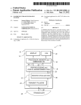
a reservoir and a plunger movable within the barrel, on the
baseplate. The infusion pump assembly and the baseplate
assembly may be con?gured to be attached to one another in
such a manner that the plunger pusher will be aligned with the
CROSS-REFERENCE TO RELATED
APPLICATION
plunger.
This application claims the bene?t of US. Provisional
Application Ser. No. 61/415,830, ?led Nov. 20, 2010 and
A baseplate assembly in accordance with at least one of the
present inventions includes a baseplate, a medicament car
entitled “Infusion Pumps,” which is incorporated herein by
reference in its entirety.
This application claims the bene?t of US. Provisional
Application Ser. No. 61/487,705, ?led May 18, 2011 and
entitled “Infusion Pumps,” which is incorporated herein by
reference in its entirety.
tridge on the baseplate de?ning a reservoir, a cannula and a
cannula inserter.
The features and attendant advantages of the present inven
tions will become apparent as the inventions become better
understood by reference to the following detailed description
when considered in conjunction with the accompanying
drawings.
BACKGROUND
BRIEF DESCRIPTION OF THE DRAWINGS
1. Field
The present devices and methods relate generally to ambu
latory infusion pumps.
2. Description of the Related Art
Ambulatory infusion pumps (also referred to herein simply
20
as “infusion pumps”) are relatively small, at least substan
tially self-contained devices that are used to introduce drugs
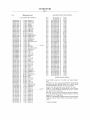
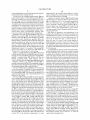
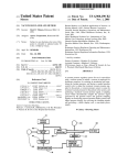
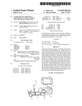
FIG. 2A is a schematic view showing use of an exemplary
and other infusible substances (collectively “medicament”)
into patients’ bodies. Some infusion pumps are con?gured to
Detailed description of exemplary embodiments will be
made with reference to the accompanying drawings.
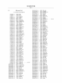
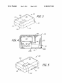
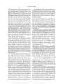
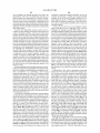
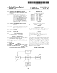
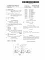
FIG. 1 is an exploded perspective view of an exemplary
infusion pump kit including an infusion pump assembly and
three baseplate assemblies.
25
infusion pump system.
FIG. 2B is a schematic view showing use of an exemplary
be worn on a belt or carried in a clothing pocket. Other
infusion pumps are con?gured to be adhered to skin in patch
like fashion. Infusion pumps are advantageous in that they
infusion pump system.
may be used to, for example, subcutaneously introduce (or
bly.
“infuse”) medicament on an ongoing or even continuous
basis outside of a clinical environment. Infusion pumps are
FIG. 3 is a perspective view of an exemplary pump assem
30
also advantageous in that they greatly reduce the frequency of
subcutaneous access events such as needle-based shots. One
example of a medicament that may be introduced by an infu
sion pump is a liquid formulation of insulin. Other exemplary
medicaments that may be introduced by an infusion pump
include, but are not limited to, drugs that treat cancers and
drugs that suppress the perception of pain.
Many conventional infusion pumps have improved patient
health and quality of life. Nevertheless, the present inventors
35
FIG. 4 is a bottom view of the exemplary pump assembly
illustrated in FIG. 3.
FIG. 5 is perspective view of the exemplary pump assem
bly illustrated in FIG. 3 with a baseplate attached and asso
ciated cartridge inserted.
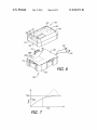
FIG. 6 is a perspective view of an infusion pump assembly
being attached to a battery recharging device.
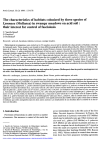
FIG. 7 is a graph showing recharging temperature during
an exemplary battery recharging method.
40
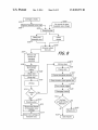
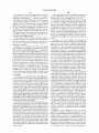
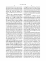
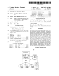
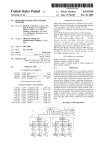
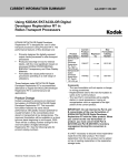
FIG. 8 is a ?ow chart showing an exemplary baseplate
have determined that conventional infusion pumps are sus
assembly removal and replacement method.
ceptible to a wide range of improvements. By way of
example, but not limitation, the present inventors have deter
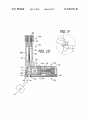
FIG. 9 is a front view showing a patient’s skin being
cleaned.
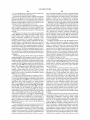
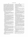
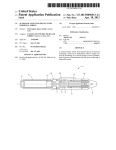
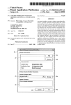
FIG. 10 is a section view showing the pump assembly
mined that it would be desirable to provide an infusion pump
that is smaller, more accurate and/or provides more opera
45
attached to the exemplary baseplate assembly, including car
tridge, a cannula inserter, and cannula, plus a pull before use
tional ?exibility than conventional infusion pumps.
plug.
SUMMARY
A system in accordance with at least one of the present
inventions includes an infusion pump assembly and a base
50
plate assembly. The infusion pump assembly may include a
housing and a rechargeable battery in the housing. The base
plate assembly may include a baseplate and a baseplate
energy supply, and may be con?gured to be attached to the
being removed.
55
infusion pump housing. Energy from the baseplate power
supply may be transferred to the rechargeable battery when
the baseplate assembly is attached to the housing.
A method in accordance with at least one of the present
inventions includes the step of securing a baseplate assembly
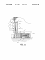
FIG. 11 is a section view showing the system illustrated in
FIG. 10 on the cleaned skin prior to cannula insertion.
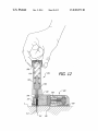
FIG. 12 is a section view showing the system illustrated in
FIG. 11 after cannula insertion.
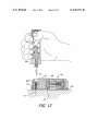
FIG. 13 is a section view showing the system illustrated in
FIG. 12 on the skin with the cannula inserted and the inserter
60
with a baseplate energy supply to an infusion pump assembly
with a rechargeable battery such that energy from the base
FIG. 14 is a section view showing the system illustrated in
FIG. 13 dispensing medicament by way of the cannula.
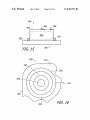
FIG. 15 is a side view ofa portion of one of the baseplate
assemblies illustrated in FIG. 1.
FIG. 16 is a bottom view ofa portion ofthe pump assembly
illustrated in FIG. 1.
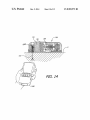
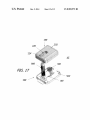
FIG. 17 is an exploded perspective view of another exem
plary infusion pump system.
plate energy supply is transferred to the rechargeable battery.
An infusion pump system in accordance with at least one of
the present inventions includes an infusion pump assembly
with a plunger pusher and a baseplate assembly with a base
plate and a medicament cartridge, including a barrel de?ning
DETAILED DESCRIPTION
65
The following is a detailed description of the best presently
known modes of carrying out the inventions. This description
US 8,905,972 B2
3
4
is not to be taken in a limiting sense, but is made merely for the
pump (FIG. 2B). Baseplate 502 is amedicament non-delivery
purpose of illustrating the general principles of the inven
baseplate that may be used to seal the cartridge 100 during
periods of non-use (e. g., by way of plug 504), thereby de?n
tions.
It should also be noted here that the speci?cation describes
ing a non-use system 12. In other words, using the same pump
structures and methods, mainly in the context of cartridge
assembly (e.g., pump assembly 200), the user may con?gure
based infusion pumps, which are especially well-suited for
the system for use as “pocket pump” or a “patch pump” by
the subcutaneous delivery of very high concentration insulin
(e.g., the U-500 insulin discussed below). Nevertheless, it
should be appreciated that the present inventions are appli
attaching the baseplate assembly to the pump assembly. The
simply selecting the appropriate baseplate assembly and
user may also switch from one con?guration to another, by
simply removing one baseplate assembly and replacing it
with another baseplate assembly. The baseplate assemblies
cable to a wide variety of infusion pumps and medicaments.
By way of example, but not limitation, many of the present
may also be con?gured for different medicaments, such as
different medicament concentrations, and/or different medi
inventions are also applicable to infusion pumps that are not
cartridge-based (e.g., pumps with re?llable reservoirs and
single use pumps). Also, the inventions may employ, for ?uid
cament amounts.
displacement, a cartridge with a plunger, a ?uid displacement
device in the form of a plunger pusher, and a drive mechanism
that includes a motor, or other ?uid displacement devices,
In some instances, the cartridge 100 may be detached from
a baseplate assembly and inserted into the pump assembly
200 prior to the baseplate assembly being secured to the pump
assembly. In other instances, the cartridge 100 may be
regardless of the type of cartridge or reservoir employed,
piston pumps (e.g., electromagnet pumps), MEMS pumps,
peristaltic pumps and any other suitable pumps as well as
20
corresponding drive mechanisms. Exemplary infusion pumps
pump assembly. For example, the baseplate assembly 300
that include a cartridge with a plunger, a ?uid displacement
device in the form of a plunger pusher, and a drive mechanism
are described in US. patent application Ser. No. 12/890,207,
?led Sep. 24, 2010, which is hereby incorporated by reference
in its entirety. The present inventions are also applicable to
medicaments such as, for example, drugs to mask pain, che
motherapy and other cancer related drugs, antibiotics, hor
mones, GLP-l, Glucagon, various other drugs that include
large molecules and proteins that may require a high level of
includes a cartridge 100 that is secured to the baseplate 500
25
(e.g., with adhesive) in exemplary system 10, while the car
tridge 100 and baseplate assembly 301 are separate structures
in exemplary system 11. Baseplate 502 is employed in those
instances where the cartridge and baseplate are detached from
one another.
It should also be noted here that, in addition to the base
30
delivery accuracy, as well as to relatively high concentration
plate, cartridge, and energy supply, some baseplate assem
blies may also include the cannula 600 as well as an inserter
800 for inserting the cannula. Other baseplate assemblies
insulin (i.e., U-200 and above) such as U-500 insulin.
with various combinations of these components (e.g. a base
plate and a cartridge that is either secured to the baseplate or
As noted above, some ambulatory infusion pumps are
intended to be worn on a belt, carried in a pocket, or otherwise
supported within a holder of some kind (referred to collec
secured to, integral with or otherwise a part of a baseplate
assembly so that the cartridge will be inserted into the pump
assembly 200 as the baseplate assembly is secured to the
35
separated therefrom) may also be provided. The baseplate
tively as “pocket pumps”). Such infusion pumps transfer ?uid
assembly components may be integrated together into a
from a reservoir to an infusion set by way of an elongate tube.
Subcutaneous access may be obtained by way of a cannula in
the infusion set. Other ambulatory infusion pumps are
single package that can be delivered to the user, as shown, for
instance, as baseplate assembly 300' in FIG. 17. In other
implementations, some or all of the baseplate assembly com
intended to be adhered to the skin at the delivery site (some
times referred to as “patch pumps”). Here, the cannula or
other subcutaneous access device may extend directly from
40
replaceable parts.
Whether con?gured as a “pocket pump” or a “patch pump,”
the system may be con?gured to provide basal delivery of
medicament in accordance with a delivery pro?le provided by
the infusion device. Given these modes of use, patients typi
cally prefer the pump to be as small as possible so that the
pump will be more comfortable, less obtrusive, and less vis
ible. In addition, patients want a device that is easy and
ponents may be provided to the user separately, as user
45
a physician by way of a clinician’s programming unit. For
example, the system may include a program that stores a
convenient to use.
number of delivery pro?les (e.g., delivery pro?les associated
Exemplary ambulatory infusion systems, which are gener
ally represented by reference numerals 10, 11 and 12 in FIG.
1, include a medicament cartridge (or “cartridge”) 100, an
with a 24-hour delivery cycle, delivery pro?les for particular
situations such as sleep or illness, and the like). Each delivery
50
ambulatory infusion pump assembly (or “pump assembly”)
200, and one of the baseplate assemblies 300, 301 and 302.
The baseplate assemblies 300, 301 and 302 each include an
energy supply 400 and a respective baseplate 500, 501 and
502. The baseplates 500, 501 and 502 are con?gured to be
attached to the pump assembly 200 and, to that end, each
includes a plate member 510, a pair of opposing connectors
pro?le speci?es multiple doses (or pump “operations”) over
time, e. g., a particular number of doses at particular times or
a particular number of doses per unit time. In some imple
mentations, a dose may be the volume associated with the
55
minimum controllable displacement of a cartridge plunger.
The system may also be con?gured to provide bolus delivery
in response to an instruction from a patient remote control. A
bolus instruction may come in response to a high glucose
512, and a hook 514.
level measurement in the case of a diabetic patient, an
The baseplates 500, 501 and 502 are also con?gured for
different modes of system operation. Baseplate 500 is a body
adherable baseplate that may be used in conjunction with a
cannula 600 that is directly connected to the cartridge 100 so
that the system 10 may be deployed as a “patch-pump” by
increase in pain level in the case of a pain management
patient, or some other symptom. The system may also be
60
con?gured to perform other functions, such as ending medi
cament delivery, in response to instructions from a patient
remote control.
securing the baseplate to the patient’s skin (FIG. 2A). Base
plate 501 is con?gured to connect the cartridge 100 to an
infusion set 503 so that the system 11 may be deployed as a
“pocket pump,” a “belt-wom pump” or some other wearable
The present infusion pumps may be used in conjunction
65
with a wide variety of remote controls. Such remote controls
may be used to, for example, allow the user to transmit
instructions to the pump assembly or facilitate communica
US 8,905,972 B2
6
5
tion between the pump assembly and the user (e.g., an alarm
condition message or other message concerning the condi
When a baseplate assembly is attached to the pump assem
bly, the pump assembly may automatically detect the version
tions of the pump assembly). An exemplary remote control
of baseplate assembly that was attached, as described further
below. Alternatively, the patient or a clinician may program
the pump, such as via a remote control, to indicate the type of
baseplate assembly attached. In a manner such as this, a
1000 (FIG. 14) may be con?gured to facilitate one, some or
all of the following operations: (1) turning the remote control
1000 on or off, (2) associating (or “assigning”) the remote
control 1000 to the pump assembly 200, (3) obtaining status
information such as medicament level, battery charge level,
and/or alarm conditions, (4) silencing the pump assembly
alarm, (5) selecting options that may be associated with the
pump assembly alarm such as type of alarm (audible, pal
pable, and/or visible) and strength/volume of alarm, (6) con
patient can access a variety of medicaments for use with a
single pump assembly.
necting the remote control to a computer to, for example,
update remote control or pump assembly ?rmware, load and
delete delivery pro?les stored in the pump assembly or
remote control, and otherwise reprogram the pump assembly
or remote control, (7) selecting medicament options such as
As such, parts of the present systems may be considered the
reusable parts, while other parts may be considered the dis
posable parts. In the illustrated embodiments, the pump
assembly 200, which includes structures such as the motor
and various mechanical structures, the pump assembly con
troller, and a rechargeable battery, is reusable, while the base
plate assembly, which may include some or all of a baseplate
(such as one of the baseplates 500-502), a cartridge 100, an
energy supply 400, a cannula 600, and a cannula inserter 800,
medicament concentrations, (8) selecting and initiating a
is disposable. Another disposable baseplate assembly 300' is
stored medicament delivery pro?le, (9) increasing and
decreasing medicament dose rate, (10) retracting the plunger
pusher from the cartridge to the home position, and/or (1 l)
shown in FIG. 17.
20
pausing a dispensing operation. A user may pause delivery in
order to remove or replace a patient applied structure (e. g., a
baseplate assembly), adjust for a current or anticipated
change body condition (e. g., low glucose, vigorous exercise),
25
follow a physician’s suggestion, or disconnect the pump
assembly from the body for any other reason.
The exemplary remote control 1000 may be con?gured to
example, but not limitation, some users prefer to avoid car
tridge ?lling procedures because they are inconvenient and
generate an indicator, based on information from a controller
for pump assembly 200, that is indicative of the amount of
time remaining in the current dispensing program and/ or the
30
and/ or the amount of time until the pump assembly battery
requires recharging. The indicator may be audible, visible,
a vacuum ?lling procedure.
35
edge of the time remaining prior to next baseplate assembly
travel or sleep), whether or not it wouldbe more convenient to 40
replace the baseplate assembly at a time prior to the end of the
dispensing program.
The system may also be provided with baseplate assem
blies con?gured for different concentrations of medicament,
45
pressure sensor may be used to detect occlusions that are
50
cially available. Humulin® R U-500 insulin, which is avail
55
by reference numeral 202 in FIG. 3, and a pump module that
is located within the housing, and is therefore not shown.
Other structures that may be carried within the housing 202
variety of baseplate assemblies can be provided containing
60
include, but are not limited to a rechargeable battery, a pump
assembly controller and associated circuitry 237 (FIG. 6), and
to baseplate assembly packaging and labeling, the different
an alarm. When the baseplate assembly is attached to the
pump assembly and medicament cartridge 100 is in opera
baseplate assemblies may include visual cues to differentiate
the various baseplate assemblies. For instance, baseplate
for the cartridge and/or baseplate of the baseplate assembly.
Brie?y, the exemplary pump assembly 200 may include an
external housing (“housing”), which is generally represented
cament ?ll volumes, to correspond to the amount of medica
ment used in the baseplate assembly lifetime. Therefore, a
assemblies with different concentrations of medicament or
different medicament ?ll volumes may use different colors
impeding, or completely preventing, medicament ?ow. To
that end, a medicament cartridge may include some or all of
the pressure sensor itself. The pressure sensor may also be
used to detect the presence of a cartridge in the pump assem
bly, as is also described below.
able from Eli Lilly and Company in Indianapolis, Ind.,
different concentrations and/or amounts of medicament, such
as various concentrations and/or units of insulin. In addition
prevents leakage from a pre?lled reservoir (e.g., pre?lled in a
vacuum with U-500 insulin) during packaging, shipping,
storage and handling, and can be manually removed by the
At least some of the exemplary implementations may
employ pressure data in various contexts. For example, a
age. However, higher concentration insulins are commer
contains 500 IU/ml. Additionally or alternative, different
baseplate assemblies may be con?gured for different medi
reservoir 104, a plunger 106, and a manifold 108. The mani
fold 108, which may include a through-bore 116, may be used
to connect the reservoir to, for example, cannulas and base
plate structures. The plunger 106 moves within the cartridge
to vary the volume of medicament within the reservoir. The
cartridge 100 may also be provided with a plug 110 that
user.
ingly, a 2 ml cartridge reservoir stores 200 IUs. One common
insulin dose is 0.5 IU, which equates to a dispensed volume of
5 microliters (ul) of U-100 per dose, 400 doses per 2 ml
reservoir, and about 4.5 days of therapy at the common dos
Referring to FIG. 10, the exemplary medicament cartridge
100 may include a barrel 102 that de?nes a medicament
replacement allows the patient to determine, based at least in
part on the current time of day and upcoming events (e.g.,
such as different types of insulin. For instance, U-100 insulin
is a relatively low concentration insulin containing 100 inter
national units (IU) of insulin activity per 1 ml and, accord
tend to involve needles. User-based re?lling also increases
the likelihood that air bubbles will be introduced into the
cartridge, while pre?lling by the manufacturer of the car
tridge and/or the medicament can be accomplished without
any substantial introduction of air bubbles using, for example,
amount of time until the next baseplate assembly replacement
palpable or combinations thereof. A time remaining indicator
may be useful for a variety of reasons. For example, knowl
The exemplary system is, as noted above, a cartridge-based
system in that medicament cartridges 100 (which may or may
not be included as part of baseplate assembly 300 or 301) are
inserted into the pump assembly 200 and later removed from
the pump assembly. The cartridges 100 may also be, but are
not required to be, pre?lled and disposable. Pre?lled car
tridges are advantageous for a variety of reasons. By way of
65
tional position within the pump assembly 200, the cartridge
plunger 106 will be proximate to and facing a plunger pusher
250 of the pump module (see FIG. 10). A drive mechanism of
the pump module may then drive the plunger pusher relative
US 8,905,972 B2
7
8
to the cartridge plunger to controllably and precisely dispense
medicament from the cartridge reservoir.
As noted above, the exemplary pump assembly 200 may
implementations, the cartridge opening 226 may be elimi
nated and replaced by a protrusion that covers the cartridge
and is part of the housing top wall 216.
include an alarm that is carried within the housing 202. The
alarm may be audible (e.g., a buzzer), palpable (e. g., a vibra
extend through (or be carried on) the housing bottom portion
A plurality of electrical contacts 228, 230 and 232 may
tor), visible (e.g., an LED with a portion that extends through
the housing 202) and/or any combination thereof. A number
of conditions may result in alarm activation in the exemplary
embodiments. For example, alarm conditions include, but are
208, as is illustrated in FIG. 4. As discussed in greater detail
below, two of the contacts (e.g., contacts 228 and 230) may be
used to electrically connect the pump assembly 200 to a
battery recharger (e.g., charger 700 in FIG. 6) and all of the
not limited to, low or dead battery, occlusion, low or empty
reservoir, hardware self-test, ?rmware error, absence of a
contacts, at least in some implementations, may be used by
the pump assembly during a baseplate identi?cation proce
baseplate, device fall-off, baseplate/pump assembly discon
dure described below.
With respect to dimensions, some embodiments of the
nection, battery charge over-temperature, telemetry fault,
motor error, unable to ?nd plunger, and/ or charging faults.
Referring to FIGS. 3-4, the housing 202 has a top portion
206 and a bottom portion 208. The top portion 206, which
exemplary housing 202 may have the following dimensions:
length dimensions of42 mm+/—l .0, 42 mm+/—0. 10, 40+/—l .0
includes two side walls 210, two end walls 212, a top wall 214
and rounded corners therebetween, generally de?nes the
internal volume in which the pump module and other pump
mm, 40+/—0. l 0 mm or 40+/—5 .0 mm; width dimensions of34
mm+/—l.0, 34 mm+/—0.10 mm, 32 mm+/—l.0 mm, 32
mm+/—0.10 mm or 32 mm+/—5 mm; overall thickness or
includes a bottom wall 216, which functions as a cover for
height dimensions of9 mm+/—l .0 mm or 9 mm+/—0. 10 mm;
and wall thickness dimensions on the order of 1.0 mm+/—0. 10
mm. Suitable housing materials include, but are not limited
mo st of the internal volume. The outer surface of the top wall
to, plastic or other materials having a modulus of elasticity of
assembly components are carried, as well as the overall vol
ume of the pump assembly 200. The bottom portion 208
20
0.2-1.0 million psi.
214 de?nes the “top face” or “top surface” of the housing 202,
and the outer surface of the bottom wall 216 de?nes the
“bottom face” or “bottom surface” of the housing.
There is a cartridge insertion opening 218 in the bottom
wall 216 through which the cartridge 100 is inserted into the
cartridge receiving area 220 when baseplate assembly 300 is
attached to pump assembly 200. Bottom wall 216 also
includes a baseplate energy supply receiving area (or
25
As mentioned above, pressure sensors may be provided to,
among other things, detect occlusions in a cannula or infusion
set tube. Occlusions may occur for any number of reasons
30
including, but not limited to, cannula kinks caused by move
ment of the pump assembly relative to a deployed cannula,
kinks in the infusion set tube, or granuloma formation at the
outlet end of a cannula. The structures that are used to sense
“recess”) 222 into which the energy supply 400 projects when
pressure may also be used to, for example, sense baseplate
a baseplate assembly (e.g., baseplate assembly 300) is
assembly attachment, medicament cartridge presence, and/or
attached to pump assembly 200. This arrangement facilitates
the transfer of energy from the baseplate energy supply 400 to
the rechargeable battery 238, as described below.
The top wall 214 of the housing 202 may be provided with
for an inserter 800 or 800'. Such access may be required for a 40
alignment within a pump assembly. In at least some imple
mentations, one portion of the pressure sensor may be part of
the medicament cartridge and another portion of the pres sure
sensor may be part of the pump assembly. Other exemplary
detectable structure arrangements include, but are not limited
to, a magnetically permeable structure carried on a diaphragm
and movable relative to a coil; and an optical element carried
cannula insertion process, such as that described below with
reference to FIGS. 10-13.
on a diaphragm and movable relative to an optical sensor; and
an electrical conductor carried on a diaphragm and movable
The top wall 214 of the housing 202 may also be provided
with a cartridge opening 226 for the top of cartridge 100. The
inserter opening 224 and cartridge opening 226 are merged
into a single opening in the illustrated embodiment. Such
openings may be separate in other embodiments. Cartridge
opening 226 facilitates observation of the medicament and
plunger within a cartridge formed from transparent material.
Additionally, in the illustrated embodiment, the pump assem
relative to a pair of switch contacts. It should also be noted
that, with respect to the implementations that include a pres
35
one or more openings. For example, an inserter opening 224
may be provided in the housing top wall 214 to enable access
45
sensor arrangements that include a cartridge portion and a
pump assembly portion. For example, a medicament car
tridge may include a pressure sensor that communicates with
50
bly 200 is con?gured (i.e., sized, shaped, etc.) such that a
portion of the associated cartridge (e.g., cartridge 100) may
protrude through the cartridge opening 226 when the base
plate assembly is in place and the cartridge is in the cartridge
receiving area 220. For example, the relative con?gurations
of the baseplate assembly 300, cartridge 100 and pump
assembly 200 may be such that the cartridge body protrudes
slightly (e.g., about 0.40-1.00 m, or ?ve percent of the
55
quickly, have high energy density, and have desirable linear
decay that facilitates accurate charge state indication.
60
Turning to FIG. 6, the exemplary rechargeable battery 238
may be carried within the pump assembly housing 202. Addi
tionally, because the battery 238 is rechargeable, e.g., via
external recharging contacts 228 and 230 or the baseplate
energy supply 400, the exemplary housing 202 does not
substantially equal to the length of the cartridge reservoir,
the opening 226 may be about 60 to 90% of the diameter and
is about 83% in the illustrated implementation. In other
rechargeable lithium ion battery. At least some implementa
tions will employ a rechargeable battery having a fully
charged, open circuit voltage of generally about 3.7 Volts, or
between about 3 0-424 Volts. One advantage of lithium poly
mer and lithium ion batteries is that they can be recharged
body will, however, be located below the inner surface of the
top wall 214. The length of the cartridge opening 226 is
with appropriate clearance, while the width is somewhat less
than the diameter of the cartridge. For example, the width of
the pump assembly by way of electrical contacts.
The battery that drives the motor may be a rechargeable
battery, such as a rechargeable lithium polymer battery or a
reservoir volume) through the opening 226 in the housing top
wall 214, as is illustrated in FIG. 5. The bulk of the cartridge
sure sensor, the present inventions are not limited to pressure
sensor arrangements that include a diaphragm, or to pres sure
65
include a door or a cover to provided access to the battery, and
the exemplary housing may be sealed (i.e., it cannot be
opened without damage thereto).
US 8,905,972 B2
9
10
One example of a battery recharger, which is generally
represented by reference numeral 700 in FIG. 6, includes
recharging circuitry 702 (e.g., a controller and power cir
cuitry) within a housing 704. The top portion of the recharger
housing 704 may include a plate 706, a pair of opposing
At least some implementations will employ an energy stor
age device 404 having a fully charged, open circuit voltage of
generally about 1 Volt, or between about 1.0-1.5 Volts.
The energy storage device 404 may be a Zinc-air battery,
the advantages of which include high energy density, small
size and wide availability. Zinc-air batteries obtain their
energy from the electro-chemical reaction of oxidiZing Zinc
with oxygen from the air. Therefore, the housing 402 may be
connectors 712, a hook 714, and electrical contacts 228R and
230R. Power and data connectors 716 and 718 may also be
provided. The respective con?gurations of the pump assem
bly 200 and battery recharger 700 are such that, when the
provided with an aperture and a cover that can be used to
prevent air from initiating the reaction and activating the
pump assembly is placed on the plate 706 with an end wall
battery. As such, in some embodiments, prior to use, a cover
212 abutting the hook 714, the pump assembly recharge con
must be removed from the housing 402. Other primary bat
teries (e.g., an alkaline battery) that may be used to recharge
rechargeable battery 238 may not require removal of a battery
tacts 228 and 230 will be electrically connected to the
recharger contacts 228R and 230R.
It should be noted here that the present pump assemblies
and battery rechargers are not limited to those which make a
direct electrical connection through the use of electrical con
tacts. By way of example, but not limitation, inductive cou
cover.
Returning to the above example, the recharging of
rechargeable battery 238 with baseplate energy supply 400
20
may use a DC-to-DC converter, for instance, within circuitry
237 (FIG. 6). The DC-to-DC converter may be used to convert
the nominal l V from the energy storage device 404 to a
25
voltage that is greater than the voltage of the battery 238, e. g.,
greater than a nominal 3.7 V, to recharge the rechargeable
battery 238. In some implementations, the recharging process
may be controlled by the pump assembly controller, such as
by circuitry 237 associated with the pump assembly control
pling may be employed.
In addition or as an alternative to the above, rechargeable
battery 238 may be recharged by the baseplate energy supply
400 carried on baseplate 500-502 (see FIG. 1). Referring to
FIG. 15, the exemplary energy supply 400 includes a housing
402 and an energy storage device 404 within the housing. Any
suitable energy storage device may be employed. Exemplary
energy storage devices include, but are not limited to, primary
cell batteries, fuel cells and capacitive storage devices. Exem
plary primary cells include alkaline batteries and Zinc-air
batteries, including those in the form of small button cells of
the type commonly used in hearing aids. Such batteries are
sometimes referred to as “disposable” batteries. The energy
supply also includes a pair of ?exible electrical contacts 406
and 408 that are respectively connected to the anode and
cathode of the energy storage device 404. A seal 410, such as
an o-ring seal, extends around the base of the energy supply
ler, or by other circuitry (such as dedicated circuitry or a
DC-to-DC converter semiconductor chip), or some combina
tion thereof. In such implementations, the pump assembly
controller (or processor circuitry, etc.) may monitor the pri
mary battery voltage and actively control the recharging pro
cess, such as when to commence or cease charging. In other
embodiments, the recharge process and/or primary battery
voltage may not be controlled or monitored, and the recharg
35
battery 238 to the medicament cartridge 100, heat from the
battery 238 could possibly increase the temperature of the
housing 402.
As noted above, the baseplate energy supply 400 projects
medicament during recharging, especially during rapid
into the baseplate energy supply receiving area 222 when a
baseplate assembly (e. g., baseplate assembly 300) is attached
40
to the pump assembly 200. To that end, the receiving area 222
is de?ned by a side wall 260 and an end wall 262 that are
45
carried on the circuit board associated with the exemplary
pump assembly controller. Temperature sensing apparatus,
50
prevent moisture ingress, when the baseplate assembly 300 is
connected to the pump assembly 200.
It should also be noted here that the present inventions are
not limited to the exemplary receiving area 222 and baseplate
energy supply 400 described above. For example, the base
sensor can sense the temperature of the medicament in the
cartridge 100 (or a temperature that is at least representative
thereof). For example, the temperature sensor 239 may be
respective con?gurations of the receiving area 222 and the
baseplate energy supply 400 are such that the energy supply
contacts 408 and 408 will engage the receiving area contacts
264 and 266, and the seal 410 will engage the side wall 260 to
recharging. The medicament temperature may be relevant to
certain medicaments such as insulin, for example, which can
be damaged and have its viability become unde?ned at about
37° C. Accordingly, a temperature sensor 239 (e.g., a ther
mistor or thermocouple) may also be carried within the pump
assembly housing 202 in such a manner that the temperature
formed in the bottom wall 216 of the housing 202. A pair of
electrical contacts, such as the illustrated annular contact 264
and circular contact 266, are located on the end wall 262. The
contacts 264 and 266 are connected to the circuitry 237. The
ing proceeds until the primary battery is exhausted.
Given the relatively close proximity of the rechargeable
55
such as a heat pipe that extends to the reservoir (not shown),
may also be included on some cartridge implementations.
The temperature information may be provided to the pump
assembly controller, or to other circuitry such as in recharger
700, or another controller (collectively referred to as the
“recharge controller”), to modulate the battery recharging
plate energy supply 400 may be provided with other types of
process as a function of temperature sensed by temperature
?exible or otherwise outwardly biased electrical contacts.
Alternatively, or in addition, the receiving area 222 may be
provided with ?exible or otherwise outwardly biased electri
sensor 239.
cal contacts. One or both sets of electrical contacts may also
Modulation of the recharging process may be accom
plished by, for example, selectively increasing or decreasing
60
be eliminated. For example, in those instances where the
baseplate energy storage device is a button battery, the base
plate energy supply and the infusion pump energy supply
receiving area may be con?gured such that contacts within
the receiving area directly contact the anode and cathode cans
65
the rate at which the battery 238 is recharged (e.g., by con
trolling current) as a function of sensed temperature. For
example, and referring to FIG. 7, the modulation process may
be designed to perform temperature control in a manner that
prevents the sensed temperature from overshooting the pre
determined maximum temperature (TMAX) as shown by the
of the battery. Inductive coupling may be employed in other
dashed lines. To that end, as temperature reaches a modula
implementations.
tion temperature (TMOD) below the maximum temperature