1
US006164920A
Ulllted States Patent [19]
[11] Patent Number:
Nazarian et al.
[45]
[54]
Date of Patent:
PERFUSION SYSTEM WITH CONTROL
Dec. 26, 2000
OTHER PUBLICATIONS
NETWORK
[75]
6,164,920
_
“BOC Puts Ohmeda Health Care Business Up for Sale”;
Inventors; Richard A_ Nazarian, Golden Valley;
Dirk R_ Smith, St Paul; James R_
Watts, WOOdbury, an of Minn;
Timothy J. Kriewall, Castle Rock,
CO1O_; Richard A_ Griewski, Canton
Township, Mich,
Medical Devices, Diagnostics & Instrumentation Reports
“The Gray Sheet”; vol. 23, No. 30; Jul. 28, 1997.
Jostra HL20 User’s Manual, Jostra AB, SWeden, 120 pages,
undated
Jostra HL20 Technical manual, Sep. 9, 1994, 46 pages.
[21] AppL NO‘: 08/722,980
SarnsTM 9000 Perfusion System Operators Manual, Sep.
1995,
pp.
i—v;
pp.
A—C;
pp.
1.1—1.11;
2.1—2.11,3.1—3.11,4.1—4.10;5.1—5.7;6.1—6.9;
7.1—7.6;
8.1—8.6; 9.1—9.4; 10.1—10.4; 11.1—11.3; 12.1—12.4;
13.1—13.2; 14.1—14.3; 15.1; 16.1—16.4; 17.1—17.14;
18.1—18.6; 19.1—19.19; 20.1—20.56, including Additional
Information insert, 4 sheets; and IndeX, pp. 21.1—21.4.
[22] Filed:
Manual, May 1996, pp. i—v; 1.1—1.22; 2.1—2.14; 3.1—3.10;
[73] Assignee; Minnesota Mining and
Manufacturing Company, St, Paul,
Minn,
3MTMSarnsTM Modular Perfusion System 8000 Operators
Sep. 30, 1996
7
4.1—4.10; 5.1—5.2; 6.1—6.2; 7.1—7.5; 8.1—8.4; 9.1—9.9;
[51]
[52]
Int. Cl. .................................................... .. F04B 41/06
US. Cl. .............................. .. 417/4; 417/18; 417/44.1;
[58]
Field of Search ................................
.. 604/65, 66, 67,
_
1014068; and Index, pp‘ 111413‘
604/65; 604/151
604/151’ 395/653’ 281’ 284’ 835’ 882’
883’ 884’ 828; 417/4’ 18’ 4411
(List continued on neXt page.)
Primary Examiner—Charles G. Freay
Assistant Examiner—Daniel E. Moses
Attorney, Agent, or Firm—Eloise J. Maki; Stephen W.
Bauer; Martin J. Hirsch
[56]
References Cited
[57]
U'S' PATENT DOCUMENTS
ABSTRACT
A medical perfusion system for use in connection With the
4,722,224
2/1988 Scheller et al. ......................... .. 73/599
medical treatment of a patient is provided With a ?rst type of
4,769,001
9/1988
. . . . . . .. 604/4
perfusion device in the form of a blood pump adapted to
5,001,642
3/1991 Botzenhardt et a1-
364/431-12
pump blood through a ?uid conduit connected to the patient
Prince
...............
5,059,167 10/1991 Lundquist et al. ...................... .. 600/17
and a Second type of perfusion device in the form of a
sensing device adapted to sense a condition and generate a
(List continued on neXt page.)
sensing signal relating to the condition. The perfusion sys
FOREIGN PATENT DOCUMENTS
electrical poWer line, means for selectively connecting the
0 578 338
0 609 688
1/1994
8/1994
0 690 291
3/1996
tem also includes an electrical poWer network having an
European Pat Off _______ __ A61M 1/16
European Pat. Off. ...... .. G06F 15/42
perfusion devices to the electrical poWer network, and a
controller With an input device for accepting control com
European Pat- Off- -
mands from an operator. The perfusion system could also
0
European Pat.
....... ..
include a Control device, Such as a pump, a
8
European 5“?
~~~~~~~~ ~~
sensing devices, and means for specifying the sensing
LII‘O
O 762 815
3/1997
can
a
.
.
........ ..
'
Eurogean Pat‘ Off‘ ~~~~~~~ n H 0 5K S/OO
0 768 060
4/1997
European Pat. Off.
A61B 5/215
24 55 229
5/1976
Germany .......... ..
A61M 1/03
WO 96/40322 12/1996
'
gregvéce that the control device should be accept feedback
'
WIPO ........................... .. A61M 1/36
20 Claims, 15 Drawing Sheets
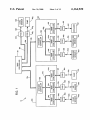
40h
MAN
CONTROLLER
10
EXTENDER
52h
30L
E
J
30k
32a
/22b
32b
309
34c
NODE
CONTROLLER
30d
E 40a
52a
50a
30%
E 40b
52b
50b
$
EXTENDER
CONTROLLER
Soc
34b
son
20
CONTROLLER
34a
34d
34a
24!
NQDE
CONTROLLER
301
.
30].
4%
52:
50c
of
52v
50f
6,164,920
Page 2
US. PATENT DOCUMENTS
5,105,441
4/1992
Borst et a1. ............................. .. 375/17
5,111,460
5/1992 BotZenhardt et al.
5,216,674
6/1993
5,222,110
6/1993 HolZinger et a1.
5,303,348
4/1994 Botlenhardtetal-
Peter et a1. ...... ..
5,572,658
11/1996 Mohr et al. ...................... .. 395/182.02
5,609,770
576227429
3/1997 Zimmerman et a1. ................ .. 210/739
4/1997 Heinze __________ __
395/2OO
371/29.1
576277531
5/1997 P0550 et aL _
341/22
.. 371/29.5
576537887
8/1997 Wahl et a1_ __
210/745
377/44
576667557
9/1997 Cassidy et aL
395/828
- 395/325
5,676,644
10/1997 Toavs 61 a1. .............................. .. 604/4
5,341,497 8/1994
5,357,518 10/1994
395/575
371/11.2
5,387,122
2/1995
439/353
5,444,626
8/1995
364/431_04
Cobe/Stockert Perfusion System, Technical Handbook,
5,448,180
5,448,561
9/1995 KienZler et a1. ........................ .. 326/15
9/1995 Kaiser et a1. ........................ .. 370/85.1
Cobe Laboratories, Inc., Rev. A, pp. 1—1—1—33; 2—1—2—66;
3—1—3—93; 4—1—4—105; and 5—1—5—29, undated (prior art).
OTHER PUBLICATIONS
_
_
574937515
2/1996 BatFhelder et al'
364/550
S 3 System, HerZ—Lungen—Maschine im Modularsystem,
5,499,336
3/1996 Preis et a1. ...... ..
395/182.02
Gebrauchsanweisung, Table of Contents, pp‘ I_XXI; pp‘
5,510,989
4/1996 Zabler et a1. ..
364/424.05
5,513,288
4/1996
5,524,213
5,539,778
6/1996 Dais 618.1.
395/20017
7/1996 KienZler 61 a1. ...................... .. 375/317
5,564,108
10/1996 Hunsaker et a1. .................... .. 395/800
Mayer
........
. . . . . . . . ..
385/30
1—1—1—2; 2—1—2—28; 3—1—3—14; 4—1—4—22; 5—1—5—262;
_
_
_
d
d
6—1—6—22> 7—1—7—8> 8—1—8—16>A—1_—A—18>un ate - _
Sarns, 3M CO- Model 9000 Perfuslon System Operatlon
Manual, Sep. 1995.
U.S. Patent
Dec. 26,2000
60
6O
Sheet 2 0f 15
QI/SO
__6O
66
22
C
6,164,920
\
40
{I
70
72
7O
7O
2O
86
68
40h
0
y
400
%
9
_ ¢ &
-6 ¢
//:_/
o
o
40e
o
o
64
FIG. 6
72,86
74 76
\
o o
40f
00000 0
84
40,,
40¢
20
.
o o o
40d
FIG. 5
6070
\
22b
220
FIG. 7
84
FIG. 8
84
FIG. 4
62
409
s2
\
88
U.S. Patent
Dec. 26,2000
20
Sheet 3 0f 15
(100
102
6,164,920
104
NON
MP
118
RAM
I
I
£83,‘?
VOLATILE
MQIQRY
I-\
I
I
V
NETWORK
DRAWING
CONTROL-
CONTROL-
LER
LER
/_
\10s
120
(114
112
V
->- DISPLAY
I/O
(
\108
I
INPUT
110
/30m
341 g
U _/34h
116
U /34i
34j
NODE
NODE
NODE
NODE
CONTROLLER
CONTROLLER
CONTROLLER
CONTROLLER
ILL
ILW
LL30,
LL30,
FIG. 9
32a
\
1/35
133
DRIVER
T
CONTROLLER ‘-——->
sw
130
/132
'
134
134
FIG. 10
30c
U.S. Patent
Dec. 26, 2000
Sheet 4 0f 15
6,164,920
34a
ENABLE!
DISABLE
\
DATA
,434
+24v
——152
._-120a
144
CODE‘
152
154
\
\
|-> sw
GND
~120b
~
150
F146
+5v
——120c
164
1
1521
sw
\sw
1
1
I—)
CONTROLLER
)
I\
l
_
f\
\14o
<—— DRIVER
\
17o
—-—120a
----—120b
12°C
#133
DATA
+24
+5
GND
40a
DATA
133
tun
1!s4
DRIVER
A
+24v +5v GND
XCVR
\
186
/
120a
12%
i
POWER
SUPPLY
CONTROLLER
180/
A
t
MEMORY
188/
__12oc
DEVICE
INTERFACE
190 192
194
FIG. 12
182
U.S. Patent
Dec. 26, 2000
6,164,920
Sheet 5 0f 15
/ 200
CONFIGURE
I
SELECT TYPE OF
PERFUSION CIRCUIT
SELECT FILE
h
DISPLAY
PERFUSION CIRCUIT
——*I
SELECT OPTION
226
ADD
DEVICE?
CONFIGURE
DEVICE?
SELECT
DEVICE TYPE
DISPLAY CURRENT
CONFIGURATION
I / 216
I /224
SELECT POSITION
CHANGE
CONFIGURATION
DISPLAY DEVICE
IN PERFUSION
CIRCUIT
218
/
FIG. 13A
DISPLAY
DATA?
DISPLAY
DATA
No
U.S. Patent
Dec. 26,2000
Sheet 6 0f 15
6,164,920
260
PLUG-IN
AUTO MODE?
ONLY ONE
MATCH?
Yes
SELECT
CONFIGURATION
ALREADY
CONFIGURED?
)
274
CONFIGURE DEVICE / 276
POSITION
KNOWN?
SELECT POSITION
_/ 268
DISPLAY DEVICE IN / 27o
PERFUSION CIRCUIT
FIG. 13B
U.S. Patent
Dec. 26, 2000
Sheet 7 0f 15
6,164,920
[280
DECODE DEVICE TYPE
AND PHYSICAL ADDRESS
/ 282
284
FULL POWER?
Yes
ALLOCATE LOGICAL
ADDRESS
/ 286
ENCODE STARTUP
/ 288
GRANTED MESSAGE
TRANSMIT MESSAGE
/ 29°
292
LOCAL DEVICE?
Yes / 294
ENABLE POWER VIA
LOCAL NODE CONTROLLER
+_____
ENCODE NODE ENABLE
MESSAGE
/ 296
I
298
TRANSMIT MESSAGE
/
FIG. 13C
U.S. Patent
Dec. 26,2000
Sheet 8 0f 15
ENCODE STATUS
REQUEST MESSAGE
/
BROADCAST STATUS
/ 304
6,164,920
302
REQUEST MESSAGE
*
306
START TIME-OUT
/
PERIOD
%
Fl G- 1 3D
DISOONNEOT VIA LOCAL
NODE CONTROLLER
/ 310
I
DETERMINE LOGICAL ADDRESS / 312
FROM STATUS MESSAGE
I
DETERMINE STATUS
FROM MESSAGE
/ 314
316
Yes
No
/
318
RESPOND TO
STATUS CONDITION
@I
FIG. 13E
ENCODE
DISCONNECT MESSAGE
i /338
TRANSMIT MESSAGE
U.S. Patent
Dec. 26, 2000
6,164,920
Sheet 9 0f 15
[350
352
CONTROL
COMMAND?
ENCODE CONTROL
MESSAGE
/ 354
T
f 356
BROADCAST
CONTROL MESSAGE
ENCODE ALARM
/ 360
RESET MESSAGE
+
BROADCAST ALARM /
362
RESET MESSAGE
RESET
SYSTEM?
ENCODE SYSTEM
RESET MESSAGE
/ 366
BROADCAST SYSTEM /
RESET MESSAGE
FIG. 136
368
U.S. Patent
Dec. 26, 2000
Sheet 10 0f 15
6,164,920
[370
UPDATE
_)
DISPLAY
LOG
EVENT
374
3.2205 +
380
STATUS
MESSAGE?
$23,522 +
\ass
STARTUP
REQUEST?
PROCESS _)
REQUEST
394
376
$20
>
382
3.2%}?
4+
388
UPDATE
DISPLAY
39s
FIG. 13H
STfT‘ZS
E0
—>
U.S. Patent
Dec. 26,2000
Sheet 11 0f 15
FIG. 14A
6,164,920
U.S. Patent
Dec. 26, 2000
Sheet 12 0f 15
CEXTENDER STARTUP)
PERFORM INTERNAL
6,164,920
[42°
/ 422
SELF-TESTS
424
No
Yes
TEST BUS
/ 426
42s
No
Yes
START PERIODIC
TRANSMISSION TO
BROADCAST
ERROR
MESSAGE
NODE CONTROLLER
A
WAIT FOR
PHYSICAL ADDRESS
430
/
432
/
ALL TESTS
PASSED?
BROADCAST
STARTUP REQUEST
438
V
WAIT FOR STARTUP
GRANTED MESSAGE
V
WAIT FOR
FULL POWER
T
MEASURE VOLTAGES
AND CURRENT
446
No
Yes
FIG. 15A
U.S. Patent
Dec. 26,2000
Sheet 13 0f 15
6,164,920
450
/
DECODE PHYSICAL
460
DISCONNECT
/ 452
ADDRESS OF MESSAGE
DECODE PHYSICAL
/ 462
ADDRESS OF MESSAGE
454
NO
Yes 456
TRANSMIT ENABLE SIGNAL
TO NODE CONTROLLER
464
‘
NO
Yes
4/66
TRANSMIT DISABLE SIGNAL
To NODE CONTROLLER
5
FIG. 158
FIG. 15C
U.S. Patent
Dec. 26,2000
Sheet 14 0f 15
6,164,920
CODE VALID?
Yes
/
RESTART
TIME-OUT TIMER
490
TRANSMIT PHYSICAL
ADDRESS
478
/
CONNECT DEVICE
TO DATA BUS
480
ENABLE?
DISCONNECT DEVICE f 492
FROM DATA BUS
I
DISCONNECT DEVICE / 494
FROM FULL POWER
Yes
482
/
SUPPLY FULL
POWER TO DEVICE
:84
DISCONNECT DEVICE
FROM DATA BUS
i [486
DISCONNECT DEVICE
FROM FULL POWER
FIG. 16A
FIG. 16B
U.S. Patent
Dec. 26, 2000
C POD STARTUP D
\ —
r———>+
PERFORM INTERNAL
522 /
6,164,920
Sheet 15 0f 15
DECODE MESSAGE
v
SELF-TESTS
552
524
N°
526 /
TRANSMIT CONTROL
SIGNAL TO DEvICE
554 f
Y“
i)
TEST BUS
528
FIG. 1 7B
560
NO
530
Yes,,,./
START PERIODIC
TRANsMIssION TO
BROADCAST
NODE CONTROLLER
ERROR
MESSAGE
@
562
\
ENCODE ALARM
MESSAGE
V
WAIT FOR
$\
PHYSICAL ADDREss
V
/ 532
BROADCAST
ALARM MESSAGE
554 -/
ALL TESTS
PASSED?
570
538 \
BROADCAST
STARTUP REQUEST
540
\
WAIT FOR STARTUP
ED
572 \
GRANTED+MEssAGE
542
\
WAIT FOR
FULL POWER
574
V
ENCODE MEssAGE
\
WITH SENSING
sIGNAL
MEASURE VOLTAGES
AND CURRENT
READ SENSING
SIGNAL
+
544\
FIG. 17C
V
576
BROADCAST
MESSAGE
%
FIG. 17D
6,164,920
1
2
PERFUSION SYSTEM WITH CONTROL
NETWORK
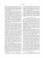
The perfusion system has means for specifying Which one of
the sensing signals is provided to the control device to
control the physical action and a controller With an input
device for accepting control commands from an operator.
The control device could be, for example, a blood pump
Which pumps blood through a ?uid conduit, and the sensing
BACKGROUND OF THE INVENTION
The present invention is directed to a medical perfusion
system adapted to handle the selective oxygenation, ?ltering
devices could be How sensors or level sensors. The speci
and recirculation of blood in connection With various medi
fying means may be composed of message-discrimination
cal procedures.
A conventional perfusion system may be used to
oxygenate, ?lter, and/or recirculate the blood of a patient
during a medical procedure. Such a perfusion system may
10
data stored in a memory in the perfusion system.
The perfusion system may also include a data communi
cations netWork for operatively interconnecting the perfu
sion devices and means for transmitting messages in the
have a ?uid conduit that removes blood from the patient
form of digital data packets among the perfusion devices
during the medical procedure, a separate ?uid conduit that
over the data communications netWork. In that case, the
specifying means could comprise means for comparing a
returns blood to the patient, one or more blood pumps that
pump blood through the conduits, and a plurality of sensing
15
devices, such as How sensors and/or level sensors associated
messages could include sensing messages related to one of
With blood pumps. The perfusion system may also include
air embolus sensors, temperature sensors, ?oW occluders,
the sensing signals and non-sensing messages not related to
one of the sensing signals, and the perfusion system could
include means for assigning a relatively high priority to the
etc.
Typically, a perfusion system is provided With a con?gu
ration speci?cally designed to be used for a particular
purpose. For example, one perfusion system may be spe
ci?cally designed as a full-function heart/lung machine,
While another perfusion system may be speci?cally designed
as a ventricular-assist system. Although it may be possible to
sensing messages and a relatively loW priority to the non
sensing messages.
These and other features of the present invention Will be
apparent to those of ordinary skill in the art in vieW of the
25
Which is provided beloW.
?guration is generally difficult and/or time-consuming.
BRIEF DESCRIPTION OF THE DRAWINGS
FIG. 1 is a block diagram of a preferred embodiment of
SUMMARY OF THE INVENTION
a perfusion system in accordance With the invention;
FIG. 2 is a perspective vieW of the main controller shoWn
schematically in FIG. 1;
FIG. 3 is a perspective vieW of one of the netWork
35
extenders shoWn schematically in FIG. 1;
FIG. 4 is a perspective vieW of one of the adapter pods
shoWn schematically in FIG. 1;
FIGS. 5—7 illustrate a number of connector con?gura
a sensing signal relating to the condition. The perfusion
tions;
system has an electrical poWer netWork With an electrical
FIG. 8 is a perspective vieW of the main controller shoWn
schematically in FIG. 1 With tWo netWork extenders and
poWer line, means for selectively connecting the perfusion
devices to the electrical poWer netWork, and a controller
eight adapter pods plugged therein;
With an input device for accepting control commands from
FIG. 9 is a block diagram of the main controller shoWn
an operator.
The means for selectively connecting the perfusion
detailed description of the preferred embodiments, Which is
made With reference to the draWings, a brief description of
convert a perfusion system designed for one purpose to a
perfusion system usable for a different purpose, such recon
The invention is directed to a medical perfusion system
for use in connection With the medical treatment of a patient.
In one form of the invention, the perfusion system includes
a ?rst type of perfusion device in the form of a blood pump
adapted to pump blood through a ?uid conduit connected to
the patient and a second type of perfusion device in the form
of a sensing device adapted to sense a condition and generate
portion of one of the sensing messages transmitted With the
message-discrimination data stored in the memory. The
45
devices to the electrical poWer netWork may include means
schematically in FIG. 1;
FIG. 10 is a block diagram of one of the extender
for providing a relatively loW level of electrical current,
means for providing a relatively high level of electrical
current, and means for selectively providing either the loW
level or high level of current. The selective connecting
controllers shoWn schematically in FIG. 1;
means may also include a poWer input, a poWer output, a
shoWn schematically in FIG. 1;
sWitch coupled betWeen the poWer input and the poWer
output, and resistive means coupled betWeen the poWer
input and the poWer output. The perfusion system may
FIGS. 13A—13H are ?oWcharts illustrating the operation
of the main controller shoWn in FIG. 1;
FIGS. 14A—14B are exemplary illustrations of a pair of
include a data communications netWork for operatively
interconnecting the perfusion devices and means for trans
FIG. 11 is a block diagram of one of the node controllers
shoWn schematically in FIG. 1;
FIG. 12 is a block diagram of one of the adapter pods
55
mitting messages in the form of digital data packets among
perfusion circuit images generated on the display device of
FIG. 9 during operation of the perfusion system;
FIGS. 15A—15C are ?oWcharts illustrating the operation
of the extender controllers shoWn in FIG. 1;
FIGS. 16A—16B are ?oWcharts illustrating the operation
of the node controllers shoWn in FIG. 1; and
FIGS. 17A—17D are ?oWcharts illustrating the operation
of the adapter pods shoWn in FIG. 1.
the perfusion devices over the data communications net
Work.
In another aspect, the invention is directed to a perfusion
system having a ?rst sensing device for sensing a ?rst
condition and generating a ?rst sensing signal relating to the
?rst condition, a second sensing device for sensing a second
condition and generating a second sensing signal relating to
the second condition, and a perfusion device in the form of
a control device for controlling a physical action, such as the
pumping of blood, based on only one of the sensing signals.
65
DETAILED DESCRIPTION OF THE
PREFERRED EMBODIMENTS
FIG. 1 illustrates a preferred embodiment of a medical
perfusion system 10 in accordance With the invention. The
6,164,920
3
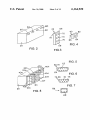
4
perfusion system 10 is adapted to handle the selective
oxygenation, ?ltering and recirculation of blood in connec
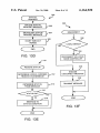
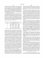
connector 70 is identical to the connectors 60 and has the
structure shoWn in FIG. 5. The connector 72, Which is shoWn
tion With a number of different medical procedures. The
perfusion system 10 may be placed in a number of different
con?gurations, each of Which corresponds to a different
medical procedure. For example, the perfusion system 10
in FIG. 6, has nine pin receptacles 74 formed in an asym
metrical housing 76 composed of an insulating material such
as plastic. The pin receptacles 74 are located to correspond
to the positions of the nine pins 62 of the connector 60.
may be con?gured as a full-function heart/lung machine, a
ventricular assist system, or a single-pump system that can
be used for various purposes, such as to perform blood
Consequently, the connector 72 has the same connector
con?guration as the connector 60 and thus can be plugged
into the connector 60.
aspiration or myocardial protection during surgery.
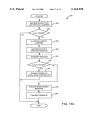
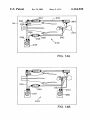
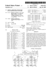
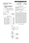
Referring to FIG. 1, the main controller 20 is connected
FIG. 4 is a perspective vieW of the adapter pods 40 shoWn
schematically in FIG. 1. Referring to FIG. 4, each adapter
to a netWork extender 22a via a data/poWer bus 30a and to
a netWork extender 22b via a data/poWer bus 30b. The
netWork extender 22a includes an extender controller 32a
pod 40 has a hexahedral housing With one side 82 on Which
a connector 84 is disposed and an opposite side on Which a
connector 86 is disposed. The connector 86 is identical to the
connected to three node controllers 34a, 34b, 34c via a
data/poWer bus 30c. The node controller 34a is connected
via a data/poWer bus 30a' to an adapter pod 40a, Which is in
connectors 72 described above (and shoWn in FIG. 6).
10
The connector 84 is adapted to be connected to a device
connector (not shoWn) that is associated With one of the
perfusion devices 50 described above. The connector 84 has
a different connector con?guration than the connectors 60,
70, 72, 86. One example of the structure of the connector 84
is shoWn in FIG. 7 to include six conductive pins 88. Since
each of the adapter pods 40 is adapted to be connected to a
turn connected to a perfusion device 50 in the form of a How
sensor 50a via a bidirectional data/poWer line 52a. The node
controller 34b is connected via a data/poWer bus 306 to an
adapter pod 40b, Which is connected to an air embolus
sensor 50b via a bidirectional line 52b. The node controller
34c is connected via a data/poWer bus 30f to an adapter pod
different type of perfusion device 50 (the pumps 50c, 50g
40c, Which is connected to a blood pump 50c via a bidirec
may be different types of pumps, such as a roller pump or a
tional line 52c.
The netWork extender 22b includes an extender controller
32b connected to three node controllers 34d, 34e, 34f via a
25
data/poWer bus 30g. The node controller 34a' is connected
via a data/poWer bus 30h to an adapter pod 40d, Which is
centrifugal pump), the connector 84 disposed on each of the
adapter pods 40 may have a different connector con?gura
tion.
Since the connectors 60 of the main controller 20 and the
connectors 70 of the netWork extenders 22 have the same
connector con?guration as the connector 86 of the adapter
connected to a pressure sensor 50d via a bidirectional line
52d. The node controller 346 is connected via a data/poWer
bus 30i to an adapter pod 406, Which is connected to a
temperature sensor 506 via a bidirectional line 526. The node
controller 34f is connected via a data/poWer bus 30j to an
pods 40, it should be noted that any of the adapter pods 40
adapter pod 40f, Which is connected to a How occluder 50f
FIG. 8 illustrates the main controller 20 having the
netWork extenders 22 and the adapter pods 40 connected to
it. Each of the adapter pods 40 of FIG. 8 Would be connected
may be plugged into any of the connectors 60, 70. As a
result, any combination of perfusion devices 50 may be
connected to the main controller 20.
via a bidirectional line 52]”.
The main controller 20 is operatively coupled to a blood
pump 50g via a bidirectional line 52g connected to an
to a respective one of the perfusion devices 50 shoWn in FIG.
adapter pod 40g. The pod 40g is connected to the main
controller 20 via a data/poWer bus 30k. The main controller
20 is operatively coupled to a level sensor 50h via a
bidirectional line 52h connected to an adapter pod 40h,
Which is connected to the main controller 20 via a data/
poWer bus 30l.
As used herein, the term “perfusion device” is a device
45
designed to be used in a medical perfusion system, including
but not limited to a blood pump such as a centrifugal or roller
pump, a ?oW sensor, a pressure sensor, a temperature sensor,
a level sensor, an air embolus sensor or an occluder.
Electronics
Mechanical Structure of Network Components
FIG. 2 is a perspective vieW of a portion of one mechani
cal embodiment of the main controller 20. Referring to FIG.
2, the main controller 20 has four netWork connectors 60,
1 via a respective connector (not shoWn) attached to the
perfusion device 50 by a cable.
Although the form of the netWork extenders 22 shoWn in
FIGS. 3 and 8 makes the resulting control unit compact,
netWork extenders having different structures could be used.
For example, instead of having the connector 72 ?xed on the
housing 66, the connector 72 could be connected to the
housing 66 via a cable. Alternatively, the housing 66 could
be eliminated, and the connectors 70, 72 could be intercon
nected via cables.
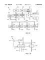
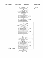
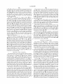
FIG. 9 is a block diagram of the main controller 20 shoWn
schematically in FIG. 1. Referring to FIG. 9, the main
controller 20 has a microprocessor (MP) 100, a random
55
access memory (RAM) 102, a nonvolatile memory 104 such
Which are shoWn schematically. Each of the netWork con
nectors 60 is identical and has the same connector con?gu
ration. FIG. 5 illustrates the structure of the connectors 60.
draWing controller 108, and an input/output (I/O) circuit
As shoWn in FIG. 5, each connector 60 may be, for example,
a standard personal computer connector having nine con
ductive pins 62 partially surround ed by an a symmetrical
such as a CRT or a ?at-panel display, and an input device
metal housing 64.
screen on the display device 114.
as a hard disk or a ?ash RAM, a netWork controller 106, a
110, all of Which are interconnected by an address/data bus
112. The U0 circuit 110 is connected to a display device 114,
116, such as a keyboard or electronic mouse or a touch
FIG. 3 is a perspective vieW of one embodiment of the
The main controller 20 also includes a poWer supply
netWork extenders 22 shoWn schematically in FIG. 1. Each
circuit 118 that is connected to an outside source of AC
netWork extender 22 has a hexahedral housing 66 With one
side 68 on Which three connectors 70 are disposed and an
opposite side on Which a connector 72 is disposed. Each
poWer and Which includes an internal transformer (not
shoWn) that generates +5 volt and +24 volt DC poWer on a
pair of electrical poWer lines relative to a ground line, Which
6,164,920
5
6
lines are schematically designated 120 in FIG. 9. The
electrical power and ground lines 120 are provided to each
of four node controllers 34g—34j via a data/poWer bus 30m
and to the other node controllers 34 via the other portions of
the netWork bus 30. The data/poWer bus 30m includes a
on the line 133 via a driver 184. The controller 180 receives
netWork messages from the data bus 152 and transmits
messages onto the data bus 152 via a transceiver 186.
The controller 180 is connected to a memory 188 and to
a device interface circuit 190. The device interface circuit
number of data communication lines Which are connected to
190 has a plurality of data lines 192 and a plurality of
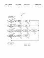
the netWork controller 106. FIG. 10 is a block diagram of the
electrical poWer lines 194 Which are connected to the
extender controller 32a shoWn schematically in FIG. 1 (the
design of the extender controllers 32a, 32b is the same).
Referring to FIG. 10, the extender controller 32a has a
controller 130 and a sWitch 132, both of Which are connected
to the data/poWer bus 30a. The extender controller 32a is
connected to its parent node controller 34g via a bidirec
tional signal line 133. As used herein, a “parent” device is a
connected device that is closer to the netWork controller 106
(FIG. 9) of the main controller 20. The node controller 34g
perfusion device 50a via the connector 84 (FIG. 7). The
10
adapter pod 40 is connected, the signals on the data lines 192
might include, for example, digital or analog signals (e.g.
15
4—20 ma signals) relating to the control of the perfusion
device 50, such as a desired pump speed or mode of
transmits a unique physical address to the extender control
ler 32a via the line 133, and the extender controller 32a
includes a driver circuit 135 Which is used to periodically
transmit a check-in code to the node controller 34g via the
line 133. The check-in code and the physical address may be
the same binary code.
FIG. 11 illustrates a block diagram of the node controller
34a shoWn schematically in FIG. 1 (the design of all the
node controllers 34 is the same). Referring to FIG. 11, the
controller 180 causes various types of data signals to be
transmitted to the perfusion device 50a via the data lines
192.
Depending on the type of perfusion device 50 to Which an
operation. The number of data lines 192 used depends on the
particular perfusion device 50 to Which the adapter pod 40
is connected.
The controller 180 also causes various types of electrical
poWer to be transmitted to the perfusion device 50 via the
poWer lines 194. These types of poWer include, for example,
+5 volt DC poWer or +24 volt DC poWer. If poWer of another
25
node controller 34a has a controller 140 Which receives an
enable signal or a disable signal from the extender controller
32a via one of the lines 134 and a periodic check-in code
voltage level is necessary, the poWer supply circuit 182 may
comprise a DC/DC converter.
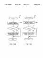
Con?guration and Display of Perfusion Circuit
from the adapter pod 40a via the line 133. The controller 140
Prior to using the perfusion system 10 for a medical
is connected to a code generator 144 via a multi-signal line
procedure, the operator connects the desired perfusion
146. The code generator 144 generates a predetermined
devices 50 to the main controller 20 by physically connect
multi-bit binary code that uniquely speci?es the physical
ing the desired adapter pods 40 and/or netWork extenders 22
address of the node controller 34a. The code generator 144
may be, for example, a number of printed metal circuit lines,
one line for each bit of the code, each line being selectively
to the main controller 20, as shoWn in FIG. 8.
Prior to the commencement of a medical procedure, the
35
perfusion system 10 is con?gured during a con?guration
connected either to +5 volts (logic “1”) or to ground (logic
process illustrated in FIG. 13A, Which is a ?oWchart of a
“0”).
con?guration computer program routine 200 executed by the
composed of tWo individual data lines, that is part of the
data/poWer buses 30c, 30d (and the other buses 30 that make
main controller 20. Referring to FIG. 13A, at step 202 the
program generates a visual prompt to the operator to request
Whether a previous con?guration ?le should be loaded from
the memory 104 of the main controller 20. A con?guration
up the network) . When the sWitch 150 is open, the data
?le generally includes image data corresponding to an image
The controller 140 selectively operates a sWitch 150 that
either connects or disconnects a data bus 152, Which may be
of a perfusion circuit, Which may include an outline of the
buses 30c, 30d are disconnected, and When the sWitch 150
is closed, the buses 30c, 30d are connected to enable data
communications betWeen the adapter pod 40a and the other
45
devices connected to the netWork 30.
The controller 140 also operates a sWitch 154 that controls
represented by a different image, depending upon the type of
perfusion device. For example, pumps may be represented
Whether +24 volt DC poWer (relative to a ground line 1206)
on a electrical poWer line 120a is supplied to the adapter pod
by a pump image, Whereas a How sensor may have a
different image.
40a and a sWitch 158 that controls Whether +5 volt DC
poWer on an electrical poWer line 120b is supplied to the
The con?guration ?le may also include data relating to the
perfusion devices 50, such as the manufacturer and model
number of the device, the desired operational mode of the
adapter pod 40a. The electrical poWer lines 120a, 120b are
part of the data/poWer buses 30c, 30d and the other buses 30
that make up the netWork. A resistor 162 is connected in
parallel With the sWitch 154, and a resistor 164 is connected
in parallel With the sWitch 158. The resistors 162, 164 act as
device, numeric limits at Which an alarm should be
55
current-limiting resistors Which prevent large amounts of
connected to a driver circuit 170 Which is used to transmit
poWer supply 182 connected to the electrical poWer lines
120a, 120b. The controller 180 may transmit a check-in code
triggered, and identi?cation of any associated perfusion
device. TWo perfusion devices may be “associated” if one
device that is used to control a physical process, referred to
herein as a control device, is to receive feedback from
another perfusion device, referred to herein as a sensing
device.
current from being draWn from the poWer lines 120a, 120b
When the sWitches 154, 158 are open. The controller 140 is
the physical address generated by the code generator 144 to
the adapter pod 40a via the line 133.
FIG. 12 illustrates a block diagram of the adapter pod 40a
shoWn schematically in FIG. 1. Referring to FIG. 12, the
adapter pod 40a has a controller 180 Which is poWered by a
patient, images of a plurality of ?uid conduits connected to
the patient, and images of the various perfusion devices 50
used in the system 10. Each perfusion device 50 may be
For example, referring to FIG. 1, the pump 50g could be
controlled based on feedback generated by either the level
sensor 50h (Which Would generate a signal indicative of ?uid
level Within a ?uid reservoir) or the How sensor 50a. In the
65
former case, the pump 50g could be controlled to maintain
a predetermined level of ?uid Within the reservoir, and in the
latter case the pump 50g could be controlled to maintain a