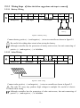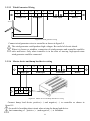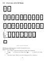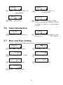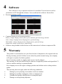
1
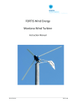
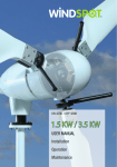
Wind & Solar Hybrid Controller User Manual Model: HY-C30-48BSLS Thank you for purchasing our product(s). The manual is provided to people who need to install and operate the controller. Read this manual before any work with controller and keep it carefully. The contents of this manual will be periodically updated or revised if necessary. However discrepancies cannot be excluded. Please refer to the actual product(s). Symbols The following symbols are used throughout this manual to indicate potentially dangerous conditions or mark important safety instructions. WARNING: Indicates a potentially dangerous condition. Use extreme caution when performing this task. INDICATION: Indicates a procedure or function that is important. NOTE: Indicates a specific description for content. General Safety Information Before receive the product, check it carefully. Make sure whether the product is damaged during transport. If it is damaged, contact the shipping company or our company immediately. All installation and electrical work must only be performed by professional personnel. Without any professional guidance, do not disassemble or attempt to repair the controller. Do not use the controller without batteries. Do not cut off the connection of controller and batteries when controller is working normally. Keep children away from controller. Do not allow water to enter the controller. Confirm that power connections are tightened to avoid excessive heating from a loose connection. Make sure cables are suitable for system. II Contents 1 2 Product Introduction ................................................................................................................................................ 1 1.1 Functions and Features ..................................................................................................................................... 1 1.2 Appearance ....................................................................................................................................................... 3 1.3 Dimensions ........................................................................................................................................................ 4 Installation and Electrical Connection ..................................................................................................................... 5 2.1 Installation......................................................................................................................................................... 5 2.2 Electrical Connection......................................................................................................................................... 6 3.1 Description of Buttons ...................................................................................................................................... 9 3.2 Overview of LCD Menu ................................................................................................................................... 10 3.3 Parameters Browsing ...................................................................................................................................... 11 3.4 System Information ........................................................................................................................................ 14 3.5 Wind Information ............................................................................................................................................ 14 3.6 Solar Information ............................................................................................................................................ 15 3.7 Optional Function 1: Date and Time Setting .................................................................................................. 15 4 Software ................................................................................................................................................................. 16 5 Warranty ................................................................................................................................................................. 16 III 1 Product Introduction This kind of wind and solar hybrid controller is special design for off-grid wind solar hybrid generation system. Appearance is elegant, operations are easy. It also makes the course wind generator and solar panels charge to batteries safely and efficiently. 1.1 Functions and Features 1.1.1 Basic Functions Wind Turbine and Load Adaptive Impedance Matching, maximize energy utilization. There is internal resistance in Wind generators, batteries and loads. According to impedance matching principle, only when input impedance equals to output impedance, power utilization is maximal, get the maximum power. Protect wind generator from over-revolution speed, over-voltage and over-current Max revolution speed, max voltage and max current of wind generator could be set. Once the actual revolution speed, voltage or current over the set ones, PWM intelligent unloading will start automatically. That protect wind generator. Intelligent limiting of batteries max current Batteries maximum capacity could be set through this controller. According to the set maximum capacity, controller could calculate the maximum charging current. Then batteries will be protected. Function of manual brake Wind charging manual switch On the controller you can manually set whether using wind charge to battery. Solar charging manual switch On the controller you can manually set whether using solar charge to battery. 1 BOOST and BUCK function in one (If do not buy Boost & Buck Wind Solar Controller, there is no this function) Once wind generator voltage is lower than battery voltage, controller starts boost module automatically. Wind generator voltage is increased to the charging voltage, and it is boost charging. When wind generator voltage is higher than battery voltage, in order to acquire max power, buck module of controller will be started, the generator is buck charging. Loads lower the revolution speed of wind generator, when it is breeze. That decreases the output power of wind generator. Through max current tracking (MCT) and max power point tracking (MPPT), output of wind generator is stabilized at the max balance of wind energy utilization. Combine with boost and buck function, wind energy utilization is increased. BOOST function (If do not buy Boost Wind Solar Controller, there is no this function) Once wind generator voltage is lower than battery voltage, controller starts boost module automatically to charge to battery. BUCK function (If do not buy Buck Wind Solar Controller, there is no this function) Once wind generator voltage is higher than battery voltage, controller starts buck module automatically to charge to battery. 1.1.2 Optional Function The following functions are available for purchase. USB function Record controller’s working data by USB stick. Users can analyze the data on PC. RS232 interface By serial interface communication, you could monitor the whole system, storage and analyze data. Program could be upgraded by serial interface. Connect PC and controller by serial interface. You could set the parameters on PC and controller simultaneously. Software is free, easy to operate and no need to be installed. RS485 interface Anemometer function Wind speed could be displayed on LCD, easy to observe. 2 1.2 Appearance 1 2 3 4 8 5 9 6 7 Figure1-1 Master device appearance description Item Name 1 LCD display panel 2 3 4 5 6 7 8 9 Terminal block Battery switch Wind brake switch USB RS485 interface RS232 interface System cooling fan Mounting holes Description A friendly human-computer interaction interface. Running data and configuration parameters are displayed in the LCD screen. Parameters could be set by keys on the panel. Connect wind generator, pv panel, battery and load. Disconnect battery current safely Turn on (ON) or turn off (OFF) wind braking Storage data(If don’t purchase, no USB interface) Communication interface(If don’t purchase, no this interface) Communication interface(If don’t purchase, no this interface) This fan rotates when charging current is too high, cooling the system Install controller 10 Figure1-2 Dump load device appearance description Item Name 10 Dump load device Description Connect master device Terminal block 3 1.3 Dimensions Figure1-2 Dimensions of master device Figure1-3 Dimensions of dump load device 4 2 Installation and Electrical Connection 2.1 Installation 2.2.1 Mounting Notes Read through this entire section first before beginning installation. All mounting work must only be performed by professional personnel. Disconnect all sources of power to the controller before installing or adjusting. Do not allow water and snows enter the controller. Install in locations where is dustless, airy and avoid direct sunlight. If install controller in a cabinet, make sure there is enough space for controller heat-dissipating. Keep controller away from corrosive gas and intense electromagnetic interference. Locate the product in where easy to install, electrical connection and service. 2.2.2 Mounting Steps 1. Choose mounting location.(Please refer to installation notes) 2. Check for clearance around the location; make sure there is enough space for connecting cables. 3. Prepare tools for installation. 4. Place the controller to the mounting location. 5. Check that the controller is securely mounted. 5 2.2 Electrical Connection 2.3.1 Overview of Electrical Connection Computer Dump load device + - + - Battery Wind + - Solar Figure2-1 Overview of electrical connection 2.3.2 Wiring Notes Improper operation during the wiring process can cause fatal injury to the operator or unrecoverable controller damage. Only qualified personnel can perform the wiring work. All cables must be undamaged, properly insulated and adequately dimensioned. Make sure that all cables are firmly attached. Unsecured cables create loose and resistive connections which may lead to excessive heating and /or fire. For mobile applications, be sure to secure all wiring, avoid loose connections. 6 2.3.3 Wiring Steps (Follow the bellow suggestions and steps to connect) 2.3.2.1 Battery Wiring 1 2 3 4 5 6 7 8 9 + - ~ ~ ~ + - + - Dump Load Solar Input Wind Input Battery + - Battery Figure2-2 Battery wiring Connect battery positive(﹢) and negative(﹣) wires to controller as shown in figure2-2. Be careful of avoiding short circuit when wiring the battery. Although controller has the protection of battery anti-reverse, but anti-connecting of positive (﹢) and negative(﹣) is forbidden. 2.3.2.2 Solar Wiring 1 2 3 4 5 6 7 8 9 + - ~ ~ ~ + - + - Dump Load Solar Input Wind Input Battery Solar Figure2-3 Solar wiring Connect solar positive(﹢) and negative(﹣) wires to controller as shown in figure2-3. The solar PV array may produce high voltages in sunlight. Be careful of electric shock when wiring. Although controller has the protection of solar anti-reverse, but anti-connecting of positive (﹢) and negative(﹣) is forbidden. 7 2.3.2.3 Wind Generator Wiring 1 2 3 4 5 6 7 8 9 + - ~ ~ ~ + - + - Dump Load Solar Input Wind Input Battery Wind Figure2-4 Wind generator wiring Connect wind generator wires to controller as shown in figure2-4. The wind generator could produce high voltages. Be careful of electric shock. When it is breeze or windless, connection of wind generator and controller would be safer and better. Only when controller is in the state of start-up, high-speed rotate wind generator could be connected. 2.3.2.4 Master device and dump load device wiring 1 2 3 4 5 6 7 8 9 + - ~ ~ ~ + - + - Dump Load Wind Input 1 2 3 NC + Dump Load Solar Input Battery Dump load device Figure2-5 Master device and dump load device wiring Connect dump load device positive(﹢) and negative(﹣) to controller as shown in figure2-5. Be careful of avoiding short circuit when wiring the dump load device. Anti-connecting of positive (﹢) and negative(﹣) is forbidden. 8 2.3.4 Confirm Wiring Double-check the wiring. Make sure each connection is correct. Secure no loose and resistive connections. 3 Operation 3.1 Description of Buttons Buttons Menu Description Enter into sub-screen or confirm the command. Switch between sibling menu or decrease the setting value.(Press more than two seconds change the setting value quickly ) Switch between sibling menu or increase the setting value.(Press more than two seconds change the setting value quickly ) Esc Return to parent screen or cancel the command. 9 Power On 10 8.ErrCode: B* S* W* T* 7.TP:Normal **C TM:Normal**C **C 6. Total-Energy: **W·H 5. In-Power: **W S:**W W:**W 4. Wind-Power P:**W I:**A 3. Wind:**R/min V:**V I:**A 2. Solar: V:**V I:**A 1. : 0% Low V: ** I: ** 参数浏览 Menu Main Menu 3. Solar Info Main Menu 2. Wind Info Menu Main Menu 1. System Info Menu 2. Wind Info Vmax:**V 6/9 2. Wind Info Amax:**A 7/9 2. Wind Info Time:**min 8/9 2. Wind Info CutIn: **V 9/9 1. System Info 7/9 Flot: **V 1. System Info Out: **V 8/9 1. System Info Rout: **V 9/9 2. Wind Info Brake:ON 4/9 1. System Info RLow:**V 4/9 1. System Info RFull: **V 6/9 2. Wind Info Pole: **D 3/9 1. System Info Low:**V 3/9 2. Wind Info M-SW: ON 5/9 2. Wind Info Rota:**R 2/9 1. System Info Energy: ADD 2/9 1. System Info FuLL: **V 5/9 2. Wind Info MPPT:ON 1/9 1. System Info Batt: **Ah 1/9 3. Solar Info M-SW: ON 1/1 Menu 光伏信息 风机信息 系统信息 3.2 Overview of LCD Menu Figure3-1 Overview of LCD menu The gray shaded parameters could be set manually by users. Parameter setting steps: 1. Press “Menu” to enter the setting state, setting value would flash. 2. Press “ ” to decrease the setting value. Press “ ” to increase the setting value. 3. After step 2, press “Menu” to save the setting, press “Esc” to back out. 3.3 Parameters Browsing 3.3.1 Battery : **% Low V:Percentage **V I:**Aof **%— 1. battery power Right corner have below displays: Low—Battery over-discharge protecting Normal—Battery is normal Full—Battery over-charge protecting; Float—Floating Ft:**s —Countdown of exiting float(countdown start from 30s) V—Battery voltage I—Battery charging current 3.3.2 Solar 2. Solar : V:**V I:**A V—Solar voltage I—Solar charging current 3.3.3 Wind 3. Wind: **R/min V:**V I:**A **R/min— rotating speed of wind generator.(Normal working state is this display) Other displays: W1:Brake—wind generator is manually braked W2:**S—when battery voltage is greater than “Full”, generator is braking. Exit braking “Time” countdown. W3:**S—when rotate speed of wind generator is greater than “Rota”, generator is braking. Exit braking “Time” countdown. W4:**S—when wind generator voltage is greater than “Vmax”, generator is braking. Exit braking “Time” countdown. W5:**S—when wind generator current is greater than “Amax”, generator is braking. Exit braking “Time” countdown. W*:Stay—Exit braking “Time” countdown finish, wind generator still stay brake. “Full” could be set in 5/9 of 3.4 on page 14. “Rota” could be set in 2/9 of 3.5 on page 14. “Vmax” could be set in 6/9 of 3.5 on page 15. “Amax” could be set in 7/9 of 3.5 on page 15. “Time” could be set in 8/9 of 3.5 on page 15. V—wind output voltage I—wind charging current 11 4. Wind-Power P:**W I:**A V—wind output power I—wind output current 3.3.4 Input 5. In-Power: **W S:**W W:**W In-Power—total input power S—solar input power W—wind input power 3.3.5 Total Generated Energy 6.Total-Energy: **W·h Total-Energy—total generated energy This value is cumulative. If want to start from 0, set in 2/9 of 3.4 on page 12. 3.3.6 Temperature Protection 7. TP: Normal TM:Normal **C **C TP—controller device working temperature TL—MOS tube temperature Normal:temperature is normal. Error:temperature detection module is error. OTP:over-temperature protection **C:**Celsius degree 3.3.7 Error Code 8.ErrCode: B* S* W* T* B1—battery over-discharge B2—battery over-charge S1—solar input voltage is high S2—solar charging module short-circuit fault S3—solar charging module open-circuit fault W1—wind generator is manually braked W2—battery voltage is greater than “Full”, wind generator brakes W3—wind generator rotate speed is greater than “Rota”, generator brakes W4—wind generator voltage is higher than “Vmax”, generator brakes W5—wind generator current is greater than “Amax”, generator brakes W6—brake module short-circuit fault W7—wind charging module short-circuit fault 12 W8—wind charging module open-circuit fault W9—wind input voltage is high T1—MOS tube detection module fault T2—MOS tube over-temperature protection T5—controller device detection module fault T6—controller device over-temperature protection *0—work normal 3.3.8 USB (This is optional function, if not purchase, there is no the following display) A1. USB** ****-**-** **:**:** ****-**-**—Year-Month-Day。Values could be set in 3.9, on page 16 USB**—USB state USB interface has the following states: USBOK—USB well connected USBNC—USB not connected USBdErr—USB conversion module damaged or not connected USBFULL—USB stick is full **:**:**—Hour: Minute: Second. Values could be set in 3.9, on page 16 3.3.9 RS485(This is optional function, if not purchase, there is no the following display) A2. Device-Addr: 1 Device-Addr— Device address, for Modbus communication 3.3.1 Anemometer (This is optional function, if not purchase, there is no the following display) A3. Wind-Speed: ***m/s Wind-Speed—Wind speed 13 3.4 System Information 1. Main Menu System Info 1. System Info Batt: **Ah System Info—system information 1. System Info Energy:ADD Batt—battery capacity 1. System Info Low: **V 2/9 Energy— ADD:Energy cumulates CLEAR:Energy clears to 0 1. System Info RLow:**V 1. System Info Full: **V 4/9 5/9 Full— battery over-charge limit voltage 1. System Info Flot: **V 6/9 7/9 Flot—floating voltage RLow—battery over-charge limit recovery voltage 1. System Info Out: **V 3/9 Low—battery over-discharge limit voltage RLow—battery over-discharge limit recovery voltage 1. System Info RFull: **V 1/9 1. System Info ROut: **V 9/9 8/9 Out—over load limit voltage This controller has no output. ROut—over-load limit recovery voltage This controller has no output. 3.5 Wind Information Main Menu 2. Wind Info 2. Wind Info MPPT:ON Wind Info—wind information 2. Wind Info Rota:**R MPPT—wind MPPT function switch. ON: turn on OFF: turn off If do not purchase the function of Boost/Buck/Boost & Buck, it would display “NONE”. 2. Wind Info Pole: **D 2/9 2. Wind Info M-SW:ON 4/9 Brake—manual braking switch ON: turn on OFF: turn off 3/9 Pole—wind generator pole logarithm Rota—maximum rotate speed of wind generator. 2. Wind Info Brake:ON 1/9 14 5/9 M-SW—wind charging manual switch ON: turn on OFF: turn off 2. Wind Info Vmax:**V 2. Wind Info Amax: **A 6/9 Amax—Maximum current of wind generator Vmax—Maximum voltage of wind generator 2. Wind Info Time: **min 7/9 2. Wind Info CutIn: **V 8/9 Time—braking time 9/9 CutIn—wind start charging voltage If do not purchase the function of Boost or Boost & Buck, it would display “NONE” 3.6 Solar Information 3. Main Menu Solar Info 3. Solar Info M-SW:ON Solar Info—solar information 1/1 M-SW—wind charging manual switch ON: turn on OFF: turn off 3.7 Date and Time Setting (If don’t purchase the USB function, there is no the following display) Main Menu A1. Date Time A1. 2012-03-22 1-YEAR 10:44:52 1-YEAR—“year” setting Date Time—date and time A1. 2012-03-22 2-MONTH 10:44:52 A1. 3-DAY 3-DAY—“day” setting 2-MONTH—“month” setting A1. 2012-03-22 4-HOUR 10:44:52 A1. 5-MIN 4-HOUR—“hour” setting A1. 6-SEC 2012-03-22 10:44:52 2012-03-22 10:44:52 5-MIN—“minute” setting 2012-03-22 10:44:52 6-SEC—“second” setting 15 4 Software The software is easy to operate need not to be installed. You can browse and set parameters on PC through the software. Users could ask the software from sellers. Browsing interface on PC: Contents displayed on browsing interface: Battery: voltage; charging current; power; power obtained; generated energy obtained. Solar: voltage; charging current; charging power; generated energy. Wind turbine: voltage; charging current; charging power; generated energy. Output load: voltage; current; power; output energy. Software using method could reference to the instruction of software compressed file. 5 Warranty The product is warranted for one year from the date of shipment to the original end user. During warranty period, if failure occurs when the product normal using, our company will repair or replace the failure product. Out of warranty period, we supply repair service, but for charges. This warranty is only provided to buyers who have bought the product and signed the CI with us, and the warranty is nontransferable. Our company reserves the right to change products and without notice when products update. This warranty does not apply under the following conditions: Damage by not operating in accordance with user manual. Damage by accident, negligence, abuse or improper use. Unauthorized product modification or attempted repair. Damage occurring during shipment 16 Parameters Model HY-C30-48BSLS Rated wind power 3KW External dump load device Yes Rated solar power 900W Nominal system voltage 48V Battery over-discharge limit voltage(Low) 40.8V(adjustable) Battery over-discharge limit recovery voltage(Rlow) 46.5V(adjustable) Battery over-charge limit voltage(Full) 58.8V(adjustable) Battery over-charge limit recovery voltage(RFull) 52.8V(adjustable) Float voltage(Flot) 54.0V(adjustable) Wind dumpload rotate speed(Rota) 800R(adjustable) Wind pole logarithm(Pole) 4D(adjustable) Wind start charge rotate(CutIn) 300R Wind dumpload voltage(Vmax) 100V(adjustable) Dump load control mode Over rotate speed limiting, Over voltage limiting, Over Current limiting, PWM Wind charging mode MPPT and PWM Solar charging mode PWM Display mode LCD Battery: voltage; charging current; Percentage of battery power. Display content Wind: voltage; charging current; rotate speed; output current; output power Solar: voltage; charging current. System: state; generated energy; error code Operating temperature & Relative humidity Quiescent power drain ﹣20~﹢55℃/35~85%RH(Non-condensing) ≤3W Battery: over-discharge protection; over-charge protection; anti-reverse Protection type connection, outside switch. Wind: Over rotate speed protection, over voltage protection, over current protection. Master device size 423mm*300mm*173.76mm Master device package size 510mm*250mm*395mm Master device net weight 11Kg Master device gross weight 12.5Kg Dump load device size 420mm*302.40mm*154.40mm Dump load device package size 510mm*250mm*395mm Dump load device net weight 8.0Kg Dump load device gross weight 9.5kg Optional function ■ RS232 □ RS485 □ USB □ Anemometer function 17