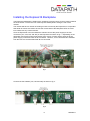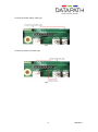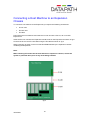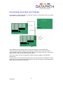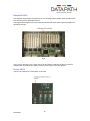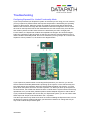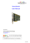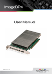
1
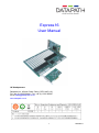
Express16 User Manual UK Headquarters Datapath Ltd., Alfreton Road, Derby, DE21 4AD, UK Tel: +44 (0) 1332 294441 Fax: +44 (0) 1332 290667 Email [email protected] www.datapath.co.uk 1 10/02/2011 Contents Contents .......................................................................................................... 2 Specifications: .................................................................................................. 3 Introduction ...................................................................................................... 4 Features ................................................................................................................................. 4 Unpacking ........................................................................................................ 5 Requirements ......................................................................................................................... 5 Installing the Express16 Backplane ................................................................. 6 Express16 slot layout ............................................................................................................. 9 Connecting a Host Machine to an Expansion Chassis................................... 10 Connecting more than one Chassis ............................................................... 11 Express16 LED’s.................................................................................................................. 12 Ex-Link LED’s....................................................................................................................... 12 Troubleshooting ............................................................................................. 14 Configuring Express16 for Limited Functionality Mode ....................................................... 14 Datapath Limited ............................................................................................ 15 Technical Support ................................................................................................................ 15 Copyright Statement ............................................................................................................ 15 Index .............................................................................................................. 17 2 10/02/2011 Specifications: Express16 Kit Power requirements (unpopulated chassis): 3.3V, 5.6A 12V, 4.2A Total 70W typical, 80W maximum Power: 24-Pin ATX PSU Chassis: ATX form factor 8 x 32bit PCI-X, 8 x 64bit PCI-X Environment: Express16/ Ex-Link / H-Link Operating Temperature 0 to 35 degC Storage Temperature: -20 to 70 degC Relative Humidity: 5% to 90% non-condensing 3 10/02/2011 Introduction The Datapath Express16 backplane provides 16 PCI-X slots which can be used with the Datapath Ex-Link and H-Link cards to provide a PCI expansion system for a standard PC. Features 16 slot PCI-X backplane. 8 x 32bit PCI-X slots and 8 x 64bit PCI-X slots Use as a PCI-X expansion backplane for a standard PC using the Ex-Link and H-Link cards Compatible with a standard 4U IPC chassis Support for daisy chaining multiple backplanes PCI Switch Fabric providing 20 Gb/s peak system bandwidth effectively providing each of the 16 PCI-X slots its own dedicated PCI-X bus 4 10/02/2011 Unpacking Your packing box should contain the following items: Express16 Backplane Ex-Link Card H-Link Card Ex-cable (optional) Datapath CD containing the user manual Note: All PCB’s are static sensitive and are packed it anti-static materials. Please keep the Express16 Backplane and any plug-in card in its packaging until you are ready to install and observe anti static precautions when installing this product. Requirements To install the Express16 backplane you require: Appropriate ATX Power supply Chassis Host Computer Choice of Power Supply The power supply must be capable of delivering sufficient power to the Express16 and to any PCI cards installed. The total power required for any system is calculated by adding together the maximum power requirement for all PCI cards in the system and the requirements of the Express16 back plane. The power requirements for all Datapath products can be found in the relevant User Manuals. It should be noted that the specific power requirements are in respect of sustained power usage and that PCI cards can, on occasions, instantaneously draw more power than the numbers given in the User Manuals. Therefore it is recommended that the chosen power supply unit has sufficient power overhead above the total calculated requirement. For large systems Datapath recommends a 1350W Redundant PSU as used on the IPC-X16. 5 10/02/2011 Installing the Express16 Backplane The Express16 backplane is fixed into the chassis by screwing down on the mounts located in the host chassis. Ensure the rear of the Express16 backplane is facing the rear of the chassis. The chassis will have a number of locating mounts not used by the Express16, it is important that stand off mounts are used to ensure the reverse side of the backplane does not come into contact with any unused mounts. Once the Express16 is secured inside the chassis connect the power supply to the four connectors (J27, J28, J29, and J30) on the Express16 as shown in fig.1. Depending on the application and system power requirements (see Choice of Power Supply page 5) all four power supply connectors need not be connected. However, if four connectors are available from the PSU it is recommended that all are connected. fig.1 Connect the fan headers (J24, J25 and J26) as shown in fig. 2 fig 2 6 10/02/2011 7 10/02/2011 Connect the Power Switch cable (J3). fig.3 Connect the power LED cable (J6). fig.4 8 10/02/2011 Express16 slot layout fig.5 9 10/02/2011 Connecting a Host Machine to an Expansion Chassis To connect a host machine to the Express16 you require the following accessories: H-Link card Ex-Link card Ex-cable Power down the host machine and insert the H-Link card into a free x4, x8 or x16 PCI Express slot. Insert the Ex-Link card into the Expansion Interface slot on the Express16 as shown in fig.6. Connect the H-Link and Ex-Link cards using the Ex-cable as shown in fig.6. When powering up switch on the host machine first followed by the expansion chassis containing the Express16. Note: When inserting PCI cards into the host machine or expansion chassis, ensure the system is powered down prior to any cards being installed. fig.6 10 10/02/2011 Connecting more than one Chassis It is possible to connect more than one expansion chassis to a host machine (fig.7) increasing the number of PCI slots available. fig.7 In this instance the host machine has an H-Link card located in a PCI Express slot. An Ex-Link card must be installed into the Expansion Interface slot in the first expansion chassis together with a D-Link card; the D-Link card does not require a PCI slot. The Ex-Link and the D-Link cards are connected using SIP cables. The Ex-Link card in the second expansion chassis should be installed in the Expansion Interface slot. Connect the H-Link card in the host machine to the Ex-Link card in the first expansion chassis and the D-Link card in the first expansion chassis to the Ex-Link card in the second expansion chassis using Ex-cables as shown in fig.7. 11 10/02/2011 Express16 LED’s The Datapath Express16 back plane has a non blocking switched fabric which provides each PCI slot with its own dedicated PCI bus. The Expres16 has eight built in LED’s which indicates that each of the eight PCI bridges are operating correctly. fig.8 If any of the LED’s are not lit, check the H-Link and Ex-link cards are sat firmly in the PCI express slots and that the Ex-cable is secured correctly then reset the host PC. Ex-Link LED’s The Ex-Link card has 3 x LED’s U20, U4 and U5. 12 10/02/2011 These LED’s indicate the system link status when both machines are powered on: U20 U4 U5 Status Action Off Off Off No link to host machine Check connectivity between host and expansion chassis. Check for faulty components. On Off Off x 1 link established N/A On On Off x 4 link established N/A On On On X 8 link established N/A 13 10/02/2011 Troubleshooting Configuring Express16 for Limited Functionality Mode If you have purchased your Express16 system as a kit and you are using your own host PC, you may experience problems when the Express16 expansion is detected by the operating system for the first time. When the system is booted for the first time with the Express16 attached, the OS will run through the new hardware it finds and configures it for use. Since each slot on the Express16 has its own dedicated bus, the OS will see many new ‘devices’ and certain systems can fail if these devices are detected by the OS in a single pass. For this reason, the Express16 contains two separate boot images. One of these images ‘hides’ the complexity of the full system so that only the first four slots are detected. This is called ‘Limited Functionality Mode’ and can be selected by moving Jumper J5 on the Ex-link expansion card to position 2-3, as shown in the diagram below. If you experience problems when connecting the Express16 to your host PC, you should select Limited Functionality Mode before powering up the system. Let the OS boot fully and let it finish finding new hardware. When the OS has finished finding new devices, you must power down the system and move J5 back to position 1-2. When you boot up the system for the second time, the OS will then detect the other 12 slots and the system should now be fully operational, but if you still have problems please contact Datapath support for further advice. If you purchased a Datapath IPC server with your Express16 system, you do not need to take these steps and Jumper J5 should be left in the 1-2 position. The above procedure only needs to be done once when installing the Express16 into a PC for the first time. However, please note that if you format the hard drive or change the OS you may need to follow this procedure again. 14 10/02/2011 Datapath Limited Datapath has a long and very successful history in the computer graphics industry. Datapath has been designing and supplying high performance, high quality graphics display systems to the world’s largest and most demanding companies and institutions since 1982. Datapath was one of the founding companies of multi-screen Windows acceleration using single and multi board solutions. Now using the very latest display technology Datapath offers some of the world’s leading multi screen graphics accelerators for the most demanding applications. As new technology advances, so we at Datapath improve the performance and functionality of both our hardware and software to give our customers more. Following a continuous development program, we pride ourselves on our support and responsive nature towards all our customers and their changing needs. As more sophisticated equipment and techniques become readily available, so we are there to exploit the power and potential that this technology presents. Technical Support Registered Users can access our technical support line using, email, and the Support page on the Datapath Web Site, usually with a response within 24 hours (excluding weekends). Via Email Send an email to [email protected] with as much information about your system as possible. To enable a swift response we need to know the following details: Specification of the PC - including processor speed Operating System Application Software Datapath Hardware / Software The exact nature of the problem - and please be as specific as possible. Please quote version and revision numbers of hardware and software in use wherever possible. Copyright Statement © Datapath Ltd., England, 2009 Datapath Limited claims copyright on this documentation. No part of this documentation may be reproduced, released, disclosed, stored in any electronic format, or used in whole or in part for any purpose other than stated herein without the express permission of Datapath Limited. Whilst every effort is made to ensure that the information contained in this on-line help is correct, Datapath Limited make no representations or warranties with respect to the contents thereof, and do not accept liability for any errors or omissions. Datapath reserves the right to change specification without prior notice and cannot assume responsibility for the use made of the information supplied. Datapath Limited acknowledges all registered trademarks used within this documentation. 15 10/02/2011 UK Headquarters and Main Sales Office Datapath Ltd., Alfreton Road, Derby, DE21 4AD, UK Tel: +44 (0) 1332 294441 Fax: +44 (0) 1332 290667 Email: [email protected] www.datapath.co.uk French Office Datapath France, 7 rue des Pinsons, 78990 Elancourt Tel: +33 1 30 13 89 34 Fax: +33 1 30 13 89 35 Email: [email protected] 16 10/02/2011 Index ATX Power supply, 5 Compatible, 4 Copyright Statement, 13 daisy chaining, 4 Datapath Limited, 13 Environment, 3 Form Factor, 3 French Office, 14 German Office, 14 H-Link, 9 increasing the number of PCIe slots, 10 LED, 11 locating mounts, 6 packing box, 5 Power requirements, 3 Relative Humidity, 3 Requirements, 5 S-Link, 10 slot layout, 8 Specifications:, 3 stand off mounts, 6 Storage Temperature, 3 Switch Fabric, 4 Technical Support, 13 Unpacking, 5 17 10/02/2011