1
User and Reference Manual
Altova UModel 2013 User & Reference Manual
All rights reserved. No parts of this work may be reproduced in any form or by any means
- graphic, electronic, or mechanical, including photocopying, recording, taping, or
information storage and retrieval systems - without the written permission of the publisher.
Products that are referred to in this document may be either trademarks and/or registered
trademarks of the respective owners. The publisher and the author make no claim to
these trademarks.
While every precaution has been taken in the preparation of this document, the publisher
and the author assume no responsibility for errors or omissions, or for damages resulting
from the use of information contained in this document or from the use of programs and
source code that may accompany it. In no event shall the publisher and the author be
liable for any loss of profit or any other commercial damage caused or alleged to have
been caused directly or indirectly by this document.
Published: 2012
© 2012 Altova GmbH
UML®, OMG™, Object Management Group™, and Unified Modeling Language™ are
either registered trademarks or trademarks of Object Management Group, Inc. in the
United States and/or other countries.
Table of Contents
1
UModel
3
2
Introducing UModel
6
3
What's new in UModel
8
4
UModel tutorial
4.1
Starting UModel
................................................................................................................. 16
4.2
Use cases
4.3
................................................................................................................. 28
Class Diagrams
4.3.1
Creating derived
...................................................................................................
classes
34
4.4
................................................................................................................. 39
Object Diagrams
4.5
Component Diagrams
................................................................................................................. 44
4.6
Deployment Diagrams
................................................................................................................. 49
4.7
.................................................................................................................
53
Round-trip engineering
(model - code - model)
4.8
.................................................................................................................
59
Round-trip engineering
(code - model - code)
5
UModel User Interface
5.1
Model Tree ................................................................................................................. 67
5.2
Diagram Tree ................................................................................................................. 71
5.3
Favorites
................................................................................................................. 73
5.4
Properties
................................................................................................................. 74
5.5
Styles
................................................................................................................. 76
5.6
Hierarchy
................................................................................................................. 79
5.7
Overview
................................................................................................................. 82
5.8
................................................................................................................. 83
Documentation
5.9
Messages
14
................................................................................................................. 20
66
................................................................................................................. 84
5.10 Diagram pane................................................................................................................. 85
5.10.1 Diagram properties
................................................................................................... 89
5.10.2 Cut, copy and...................................................................................................
paste in UModel Diagrams
91
Altova UModel 2013
1
.................................................................................................................
94
5.11 Adding/Inserting
model elements
.................................................................................................................
96
5.12 Hyperlinking modeling
elements
5.13 Bank samples................................................................................................................. 101
6
UModel Command line interface
106
6.1
File: New / Load
.................................................................................................................
/ Save options
110
7
Projects and code engineering
7.1
.................................................................................................................
115
Minimalist UModel
project - starting from scratch
7.2
.................................................................................................................
120
Importing source
code into projects
7.3
Importing Java,
.................................................................................................................
C# and VB binaries
125
7.4
Synchronizing
.................................................................................................................
Model and source code
130
7.4.1
Synchronization
tips
...................................................................................................
132
7.4.2
Refactoring code
...................................................................................................
and synchronization
134
7.5
Forward engineering
.................................................................................................................
prerequisites
135
7.6
Java code to/from
.................................................................................................................
UModel elements
137
7.7
.................................................................................................................
138
C# code to/from
UModel elements
7.8
.................................................................................................................
139
XML Schema
to/from UModel elements
7.9
VB.NET code
.................................................................................................................
to/from UModel elements
140
112
7.10 Database to/from
.................................................................................................................
UModel elements
141
.................................................................................................................
142
7.11 Including other
UModel projects
.................................................................................................................
144
7.12 Merging UModel
projects
7.12.1 2-way Project
...................................................................................................
merge
145
7.12.2 3-way Project
...................................................................................................
merge
146
7.12.3 Manual 3-way
project merge example
...................................................................................................
148
7.13 Sharing Packages
.................................................................................................................
and Diagrams
151
................................................................................................................. 154
7.14 UML templates
7.14.1 Template signatures
................................................................................................... 156
7.14.2 Template binding
................................................................................................... 157
7.14.3 Template usage
...................................................................................................
in operations and properties
158
7.15 Project Settings
................................................................................................................. 159
7.16 Enhancing performance
................................................................................................................. 160
2
8
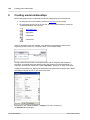
Creating model relationships
162
8.1
.................................................................................................................
165
Showing model
relationships
8.2
167
Associations,.................................................................................................................
realizations and dependencies
Altova UModel 2013
9
Generating UML documentation
172
9.1
179
Supplied SPS.................................................................................................................
stylesheet
9.2
181
User-defined.................................................................................................................
Stylesheets
10
UML Diagrams
184
10.1 Behavioral Diagrams
................................................................................................................. 185
10.1.1 Activity Diagram
................................................................................................... 186
...........................................................................................................
187
Inserting
Activity Diagram elements
...........................................................................................................
189
Creating
branches and merges
191
Activity...........................................................................................................
Diagram elements
10.1.2 State Machine
...................................................................................................
Diagram
201
...........................................................................................................
202
Inserting
state machine diagram elements
...........................................................................................................
202
Creating
states, activities and transitions
...........................................................................................................
208
Composite
states
...........................................................................................................
210
Code generation
from State Machine diagrams
...........................................................................................................
213
Working with State machine code
...........................................................................................................
220
State Machine
Diagram elements
10.1.3 Protocol State
Machine
...................................................................................................
223
...........................................................................................................
223
Inserting
Protocol State Machine elements
225
Protocol...........................................................................................................
State Machine Diagram elements
10.1.4 Use Case Diagram
................................................................................................... 227
10.1.5 Communication
Diagram
...................................................................................................
228
...........................................................................................................
228
Inserting
Communication Diagam elements
10.1.6 Interaction Overview
...................................................................................................
Diagram
231
...........................................................................................................
231
Inserting
Interaction Overview elements
10.1.7 Sequence Diagram
................................................................................................... 236
...........................................................................................................
237
Inserting
sequence diagram elements
.........................................................................................................................................
238
Lifeline
.........................................................................................................................................
239
Combined Fragment
.........................................................................................................................................
242
Interaction Use
.........................................................................................................................................
242
Gate
.........................................................................................................................................
243
State Invariant
.........................................................................................................................................
243
Messages
...........................................................................................................
248
Generating
Sequence Diagrams from source code
...........................................................................................................
251
Generate
Sequence diagrams from properties
...........................................................................................................
253
Generate
code from sequence diagram
.........................................................................................................................................
256
Adding code to sequence diagrams
10.1.8
Altova UModel 2013
Timing Diagram
................................................................................................... 260
...........................................................................................................
261
Inserting Timing Diagram elements
3
Lifeline........................................................................................................... 261
........................................................................................................... 263
Tick Mark
........................................................................................................... 264
Event/Stimulus
........................................................................................................... 264
DurationConstraint
........................................................................................................... 265
TimeConstraint
Message........................................................................................................... 266
10.2 Structural Diagrams
................................................................................................................. 268
10.2.1 Class Diagram
................................................................................................... 269
10.2.2 Composite Structure
...................................................................................................
Diagram
281
...........................................................................................................
281
Inserting Composite Structure Diagram elements
10.2.3 Component Diagram
................................................................................................... 283
10.2.4 Deployment ...................................................................................................
Diagram
284
10.2.5 Object Diagram
................................................................................................... 285
10.2.6 Package Diagram
................................................................................................... 286
...........................................................................................................
287
Inserting
Package Diagram elements
10.2.7 Profile Diagram
...................................................................................................
and stereotypes
289
291
Adding ...........................................................................................................
Stereotypes and defining tagged values
...........................................................................................................
295
Stereotypes
and enumerations
...........................................................................................................
297
User-defined
stereotype styles
299
Custom...........................................................................................................
stereotype icons - assigning
10.3 Additional Diagrams
................................................................................................................. 303
10.3.1 XML Schema
...................................................................................................
Diagrams
304
...........................................................................................................
305
Importing
XML Schema(s)
...........................................................................................................
310
Inserting
XML Schema elements
...........................................................................................................
315
Creating
and generating an XML Schema
11
Teamwork support for UModel projects
318
11.1 Creating and.................................................................................................................
editing subproject files
320
12
Source Control
326
.................................................................................................................
328
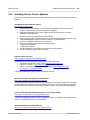
12.1 Supported Source
Control Systems
.................................................................................................................
333
12.2 Installing Source
Control Systems
12.3 SCSs and Altova
.................................................................................................................
DiffDog Differencing
340
12.4 Source Control
.................................................................................................................
Commands
346
12.4.1 Open from Source
Control
...................................................................................................
347
12.4.2 Enable Source
...................................................................................................
Control
349
12.4.3 Get Latest Version
................................................................................................... 350
12.4.4 Get
................................................................................................... 351
4
Altova UModel 2013
12.4.5
12.4.6
12.4.7
12.4.8
12.4.9
12.4.10
12.4.11
12.4.12
12.4.13
12.4.14
12.4.15
12.4.16
12.4.17
13
Get Folder(s)................................................................................................... 352
Check Out ................................................................................................... 353
Check In ................................................................................................... 354
Undo Check...................................................................................................
Out...
355
Add to Source
Control
...................................................................................................
356
Remove from...................................................................................................
Source Control
358
Share from Source
...................................................................................................
Control
359
Show History
................................................................................................... 360
Show Differences
................................................................................................... 362
Show Properties
................................................................................................... 363
Refresh Status
................................................................................................... 364
Source Control
...................................................................................................
Manager
365
Change Source
Control
...................................................................................................
366
UModel Diagram icons
368
13.1 Activity Diagram
................................................................................................................. 369
................................................................................................................. 370
13.2 Class Diagram
.................................................................................................................
371
13.3 Communication
diagram
13.4 Composite Structure
.................................................................................................................
Diagram
372
13.5 Component Diagram
................................................................................................................. 373
374
13.6 Deployment .................................................................................................................
Diagram
.................................................................................................................
375
13.7 Interaction Overview
diagram
13.8 Object Diagram
................................................................................................................. 376
13.9 Package diagram
................................................................................................................. 377
................................................................................................................. 378
13.10 Profile Diagram
.................................................................................................................
379
13.11 Protocol State
Machine
13.12 Sequence Diagram
................................................................................................................. 380
13.13 State Machine
.................................................................................................................
Diagram
381
................................................................................................................. 382
13.14 Timing Diagram
................................................................................................................. 383
13.15 Use Case diagram
13.16 XML Schema
.................................................................................................................
diagram
384
14
UModel Reference
386
14.1 File
................................................................................................................. 387
14.2 Edit
................................................................................................................. 392
14.3 Project
................................................................................................................. 395
14.4 Layout
................................................................................................................. 404
Altova UModel 2013
5
14.5 View
14.6 Tools
14.6.1
14.6.2
14.6.3
14.6.4
14.6.5
14.6.6
14.6.7
14.6.8
................................................................................................................. 405
................................................................................................................. 406
Spelling... ................................................................................................... 407
Spelling options...
................................................................................................... 410
Scripting Editor
................................................................................................... 412
Macros
................................................................................................... 413
User-defined...................................................................................................
Tools
414
Customize...................................................................................................... 415
........................................................................................................... 415
Commands
........................................................................................................... 415
Toolbars
Tools ........................................................................................................... 416
........................................................................................................... 418
Keyboard
Menu ........................................................................................................... 419
Macros........................................................................................................... 420
Plug-Ins........................................................................................................... 420
Options........................................................................................................... 420
Restore Toolbars
and Windows
...................................................................................................
421
Options
................................................................................................... 422
14.7 Window
................................................................................................................. 428
14.8 Help
................................................................................................................. 429
15
Code Generator
432
.................................................................................................................
433
15.1 The way to SPL
(Spy Programming Language)
15.1.1 Basic SPL structure
................................................................................................... 434
15.1.2 Variables ................................................................................................... 435
15.1.3 Operators ................................................................................................... 441
15.1.4 Conditions ................................................................................................... 442
15.1.5 Collections and
...................................................................................................
foreach
443
15.1.6 Subroutines ................................................................................................... 445
...........................................................................................................
445
Subroutine
declaration
...........................................................................................................
446
Subroutine
invocation
15.2 Error Codes ................................................................................................................. 447
16
Appendices
450
16.1 License Information
................................................................................................................. 451
16.1.1 Electronic Software
...................................................................................................
Distribution
452
16.1.2 Software Activation
...................................................................................................
and License Metering
453
16.1.3 Intellectual Property
...................................................................................................
Rights
454
6
Altova UModel 2013
16.1.4
Altova End User
License Agreement
...................................................................................................
455
Index
Altova UModel 2013
7
Chapter 1
UModel
UModel
1
3
UModel
UModel® 2013 Basic Edition is an affordable UML modeling application with a rich visual
interface and superior usability features to help level the UML learning curve, and includes
many high-end functions to empower users with the most practical aspects of the UML 2.4
specification. UModel is a 32/64-bit Windows application that runs on Windows Server
2003/2008/2012, Windows XP, Windows Vista, Windows 7, and Windows 8. 64-bit support is
available for the Enterprise and Professional editions.
UModel® 2013 supports:
all 14 UML 2.4 modeling diagrams
Support for the Model Driven Architecture (MDA) which allows conversion between
different programming languages (Enterprise edition only)
Ability to import and export SQL databases into UModel (Enterprise/Professional
editions only)
Teamwork support - allowing concurrent project editing
3-way project merging
Protocol State Machines
SysML 1.2 diagrams (Enterprise/Professional Edition only)
Sequence Diagram generation directly from source code
Code generation from State Machine diagrams (Enterprise/Professional Edition only)
UModel API and plugin (Enterprise/Professional Edition only)
Built-in Scripting environment and Form editor (Enterprise/Professional Edition only)
Visual Studio integration (Enterprise/Professional Edition only)
Eclipse integration (Enterprise/Professional Edition only)
Support for Version Control systems
XML Schema diagrams
Business Process Modeling Notation 1.0 and 2.0 (Enterprise/Professional Edition only)
Multiple layers per UML diagram (Enterprise/Professional Edition only)
import of Java, C# and Visual Basic binaries
hyperlinking of diagrams and modeling elements
syntax coloring in diagrams
cascading styles
unlimited Undo and Redo
sophisticated Java, C# and Visual Basic code generation from models
reverse engineering of existing Java, C#, and Visual Basic source code
complete round-trip processing allowing code and model merging
XMI version 2.4 for UML 2.0, 2.1, & 2.1.2, 2.2, 2.3, 2.4 - model import and export
generation of UModel project documentation
These capabilities allow developers, including those new to software modeling, to quickly
leverage UML to enhance productivity and maximize their results.
© 2012 Altova GmbH
Altova UModel 2013
4
UModel
UML®, OMG™, Object Management Group™, and Unified Modeling Language™ are either
registered trademarks or trademarks of Object Management Group, Inc. in the United States
and/or other countries.
Last updated: 11/13/2012
Altova UModel 2013
© 2012 Altova GmbH
Chapter 2
Introducing UModel
6
Introducing UModel
2
Introducing UModel
Altova web site:
Introduction to Altova UModel
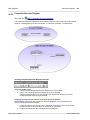
The UML is a complete modeling language but does not discuss, or prescribe, the methodology
for the development, code generation and round-trip engineering processes. UModel has
therefore been designed to allow complete flexibility during the modeling process:
UModel diagrams can be created in any order, and at any time; there is no need to
follow a prescribed sequence during modeling.
Code, or model merging can be achieved at the project, package, or even class level.
UModel does not require that pseudo-code, or comments in the generated code be
present, in order to accomplish round-trip engineering.
Code generation is customizable: the code-generation in UModel is based on SPL
templates and is, therefore, completely customizable. Customizations are automatically
recognized during code generation.
Code generation and reverse-engineering currently support Java versions 1.4.x, 5.0
and 1.6, C# versions 1.2, 2.0, 3.0, and 4.0 and Visual Basic versions 7.1, 8.0 and 9.0. A
single project can support Java, C#, or VB code simultaneously.
Support for UML templates and generics.
XML Metadata Interchange (XMI version 2.4) for UML 2.0 / 2.1.1 / 2.1.2 / 2.2 / 2.3 / 2.4
When adding properties, or operations UModel provides in-place entry helpers to
choose types, protection levels, and all other manner of properties that are also
available in industrial-strength IDEs such as XMLSpy, Visual Studio or Eclipse.
Syntax-coloring in diagrams makes UML diagrams more attractive and intuitive.
Modeling elements and their properties (font, colors, borders etc.) are completely
customizable in an hierarchical fashion at the project, node/line, element family and
element level.
Customizable actors can be defined in use-case diagrams to depict terminals, or any
other symbols.
Modeling elements can be searched for by name in the Diagram tab, Model Tree pane,
Messages and Documentation windows.
Class, or object associations, dependencies, generalizations etc. can be
found/highlighted in model diagrams through the context menu.
The unlimited levels of Undo/Redo track not only content changes, but also all style
changes made to any model element.
Please note:
This document does not attempt to describe, or explain, the Unified Modeling Language
(UML); it describes how to use the UModel modeling application, to model code and
achieve round-trip engineering results.
Altova UModel 2013
© 2012 Altova GmbH
Chapter 3
What's new in UModel
8
What's new in UModel
3
What's new in UModel
The 2013 Release version of UModel includes the following major and minor enhancements:
Support for UML 2.4
Support for SysML 1.2
Spellchecker, with extended spell-checking features
Abiltity to show .NET Properties as associations
Ability to ignore getters/setters when generating Sequence Diagrams for a project
Support for UML exception pins
The Eclipse plugins now run under Eclipse 4.2
A new Umodel edition has been introduced for the 2012 Release, namely the Basic edition.
The Basic edition has all the functionality of the previous Professional edition.
The Professional edition has all the functionality of the previous Enterprise edition, i.e. support
for SQL databases, SysML and BPMN diagrams, diagram layers, Automation support (COM
API), as well as Visual Studio and Eclipse integration.
The Enterprise editon has all the above, plus support for Model Driven Architecture, which
allows transformation of UML elements between different programming languages.
The new functionality of each of the specific versions is listed below.
The 2012 Release R2 version of UModel includes the following major and minor
enhancements:
Ability to generate code from a sequence diagram
UModel supports logical files of the IBM iSeries database and shows logical files as
views.
Supportfor IBM DB2 logical files. A logical file in IBM iSeries editions of the DB2
database represents one or more physical files. A logical file allows users to access
data in a sequence or format that can be different from the physical file. Users who
connect to IBM iSeries computers may encounter existing databases constructed with
logical files. These were previously not accessible, but are now supported in Version
2012 Release 2.
The 2012 Release version of UModel includes the following major and minor enhancements:
Snap line positioning during drag-and-drop
The 2011 Release 3 version of UModel includes the following major and minor enhancements:
Ability to show VS .NET (C# or VB.NET) properties in their own compartment
Ability to create new directories following the Java namespace hierarchy
Small enhancements in SPL to sorting of collections by name and kind as well as new
string comparison functions
The 2011 Release 2 version of UModel includes the following major and minor enhancements:
Code generation from State Machine diagrams in Java, VB.NET, or C#
Ability to customize UML Documentation using StyleVision Power Stylesheets (SPS).
Ability to automatically add operations to State Machine activities
Ability to toggle region names in States
The 2011 version of UModel includes the following major and minor enhancements:
Altova UModel 2013
© 2012 Altova GmbH
What's new in UModel
9
Teamwork support: ability to split up projects into several sections allowing concurrent
project editing
Ability to create a 3-way project merge
State Machine diagrams: automatic creation of operations when creating transitions
Sequence diagrams: automatic creation of operations (incl. parameters), by typed calls
in messages
The 2010 Release 3 version of UModel includes the following major and minor enhancements:
Support for Visual Studio 2010:
Supports new solution and project files, predefined include files supplied for .NET
framework 4.0
Support for C# 4.0
New C# 4.0 features are supported by round-trip engineering, binary import and
sequence diagram generation
Ability to create Protocol State Machines
New autolayout output option: Block
Ability to ignore operation names when generating Sequence diagrams
Ability to define Argument variables for external tools
The 2010 Release 2 version of UModel includes the following major and minor enhancements:
64-bit support
Support for UML 2.3
Ability to automatically split generated sequence diagrams into smaller sub diagrams
HTML Documentation generation includes manually defined hyperlinks between
elements
Creation of separate sequence diagrams for the getter or setter part of a property (C#,
or VB.NET)
Please note:
The following modifications in code engineering have been made due to the new UML
version 2.3 (please see Projects and code engineering Java / C# / VB.NET code
to/from UModel for more information):
The class modifiers “sealed” (C#), “NotInheritable” (VB.NET) and “final” (Java) are now
mapped to UML “isFinalSpecification”.
The Java modifier “final” for fields and methods are now mapped to UML “leaf”.
The 2010 version of UModel includes the following major and minor enhancements:
Code engineering:
Ability to resolve aliases when reverse-engineering code
small improvements in sequence diagram generation
User Interface:
Comments entered in the documentation window can now be shown/edited in
diagrams
Tagged values can now be shown in new compartment in: classes, interfaces, etc.
Hyperlinks can now be defined in the Documentation window
Hyperlinks to elements in the Model Tree are now possible
UML containment lines can now be displayed
© 2012 Altova GmbH
Altova UModel 2013
10
What's new in UModel
Documentation generation:
CSS code can be saved in HTML files, or externally
Generated image files can be saved in a specified subdirectory
File system:
Save Copy As is now supported
The 2009 version of UModel includes the following major and minor enhancements:
Support for UML 2.2
Sequence Diagram generation directly from source code
Support for Version Control Systems in the standalone version
New UML Profile Diagram
Detection and handling of types and namespaces when refactoring code
Goto feature for lifelines in sequence diagrams
Improved hierarchy window display
Ability to save UModel project files in "pretty print" format
Improved partial documentation functionality
Ability to open UModel projects from a URL
Ability to load/save currently open diagrams with the project file.
The 2008 Release 2 version of UModel includes the following major and minor enhancements:
Support for Visual Basic .NET 9.0 and C# 3.0 as well as Visual Studio 2008, Java 1.6
Merging of projects is now supported
User-defined Stereotype styles and how to define them
Enhanced Autocompletion capabilities
Automatic generation of ComponentRealizations
Importing multiple XML Schemas from a directory
Automatic generation of namespace directories for generated code
Support for ObjectNodes on Activity diagrams
Ability to generate relative links for UML documentation
UML conformant visibility icons in class diagrams
Support for Collection Associations
The 2008 version of UModel includes the following major and minor enhancements:
Visual Basic code generation from models, and reverse engineering of Visual Basic
code.
Abilty to save all project diagrams as images in one go.
Altova UModel 2013
© 2012 Altova GmbH
What's new in UModel
11
Multiline lifeline titles in sequence, communication and timing diagrams.
Support for event subelements in State Machine Diagrams: ReceiveSignalEvent,
SignalEvent, SendSignalEvent, ReceiveOperationEvent, SendOperationEvent and
ChangeEvent.
New 'go to operation' option for call messages on Sequence and Communication
Diagrams.
Signals can now have generalizations and own attributes.
Enhanced tagged value support
Ability to Find & Replace modeling elements.
Sequence diagrams:
Automatic generation of (syntactically correct) replies when adding messages to
sequence diagrams.
Static operation names are underlined in Sequence diagrams.
Ehanced "Override/Implement Operations" dialog.
Operations from bound templates can be made visible and also be overridden
Show which operations are abstract or undefined
© 2012 Altova GmbH
Altova UModel 2013
Chapter 4
UModel tutorial
14
UModel tutorial
4
UModel tutorial
This tutorial describes, and follows, the general sequence used when creating a modeling
project in UModel.
The major portion of the tutorial deals with the forward-engineering process, i.e. using UModel
to create UML diagrams and generate code as the precursor to the round-trip engineering
sections that follow. The round-trip engineering sections, describe the process from both code
and model vantage points.
The tutorial describes the following UML diagrams, and how to manipulate the various modeling
elements within them. The following diagrams and follow-on tasks are discussed:
Forward engineering process:
Use cases
Class diagrams
Object diagrams
Component diagrams
Deployment diagrams
Round-trip process (model - code - model)
Code generation from UModel
Add a new operation to the external code
Merge the external code back into UModel.
Round-trip process (code - model - code)
Import code produced by XMLSpy from a directory (or from a project file)
Add a new class to the generated model in UModel
Merge the updated project with the external code.
All the files used in this tutorial are initally available in the C:\Documents and Settings\All
Users\Application Data\Altova folder. When any single user starts the application for the first
time, the example files for that user are copied to C:\Documents and
Settings\<username>\My Documents\Altova\UModel2013\UModelExamples\ folder.
Therefore do not move, edit, or delete the example files in the initial ...\All Users\.... directory.
BankView-start.ump
is the UModel project file that constitutes the initial state of the tutorial sample. Several
model diagrams as well as classes, objects, and other model elements exist at this
stage. Working through the tutorial adds new packages, model diagrams and many
other elements that will acquaint you with the ease with which you can model
applications using UModel. Please note that the syntax check function reports errors
and warnings on this file, the tutorial shows you how to resolve these issues.
BankView-finish.ump
is the UModel project file that constitutes final state of the tutorial sample, if you have
worked through it step by step. This project file is the one used when generating code
and synchronizing it with UModel.
The OrgChart.zip file supplied in the folder is used for the round-trip engineering
process. Please unzip it in the ...\UModelExamples folder before starting the section.
Additional example files for both Java and C# programming languages are also available in the
same directory, i.e. Bank_Java.ump, Bank_CSharp.ump and Bank_MultiLanguage.ump.
These project files also contain Sequence diagrams which are described later in this
Altova UModel 2013
© 2012 Altova GmbH
UModel tutorial
15
documentation.
A section describing how to start a project from scratch and generate code, is included in the
Projects and code engineering section.
© 2012 Altova GmbH
Altova UModel 2013
16
UModel tutorial
4.1
Starting UModel
Starting UModel
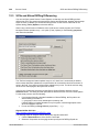
Having installed UModel on your computer:
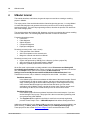
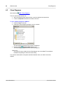
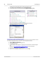
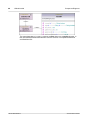
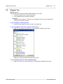
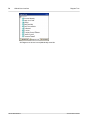
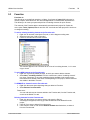
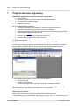
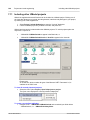
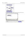
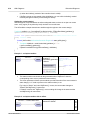
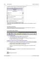
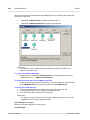
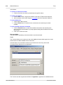
1. Start UModel by double-clicking the UModel icon on your desktop, or use the Start | All
Programs menu to access the UModel program.
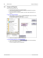
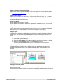
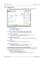
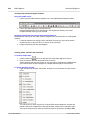
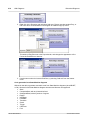
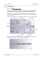
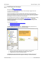
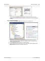
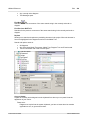
UModel is started with a default project "NewProject1" visible in the interface.
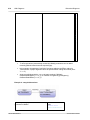
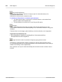
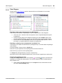
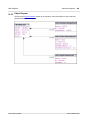
Note the major parts of the user interface: the three panes on the left hand side and the
empty diagram pane at right.
Two default packages are visible in the Model Tree tab, "Root" and "Component View".
These two packages cannot be deleted or renamed in a project.
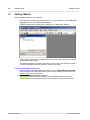
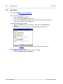
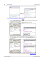
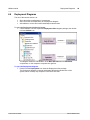
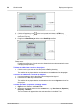
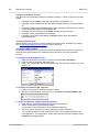
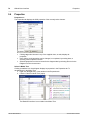
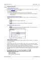
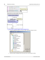
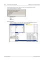
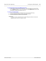
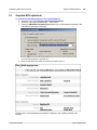
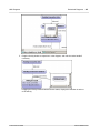
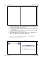
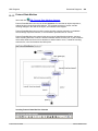
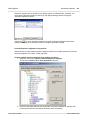
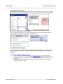
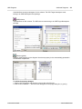
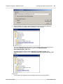
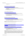
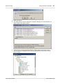
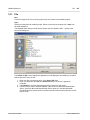
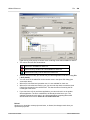
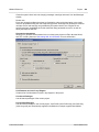
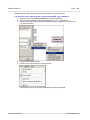
To open the BankView-start project:
1. Select the menu option File | Open and navigate to the ...\UModelExamples\Tutorial
folder of UModel. Note that you can also open a *.ump file through a URL, please see
Switch to URL for more information.
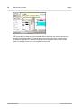
2. Open the BankView-start.ump project file.
The project file is now loaded into UModel. Several predefined packages are now
visible under the Root package. Note that the main window is empty at the moment.
Altova UModel 2013
© 2012 Altova GmbH
UModel tutorial
Starting UModel
17
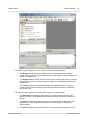
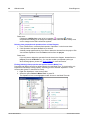
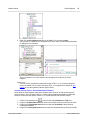
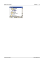
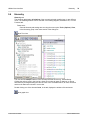
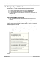
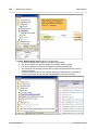
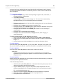
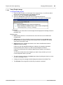
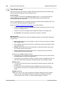
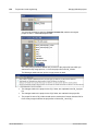
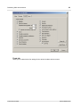
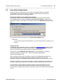
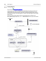
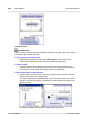
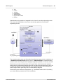
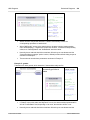
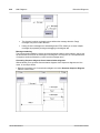
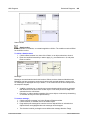
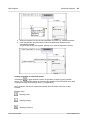
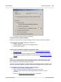
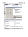
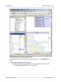
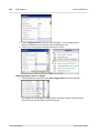
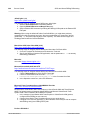
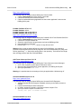
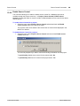
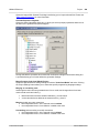
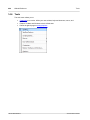
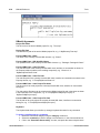
The Model Tree pane supplies you with various views of your modeling project:
The Model Tree tab contains and displays all modeling elements of your UModel
project. Elements can be directly manipulated in this tab using the standard editing keys
as well as drag and drop.
The Diagram Tree tab allows you quick access to the modeling diagrams of you project
wherever they may be in the project structure. Diagrams are grouped according to their
diagram type.
The Favorites tab is a user-definable repository of modeling elements. Any type of
modeling element can be placed in this tab using the "Add to Favorites" command of
the context menu.
The Properties pane supplies you with two views of specific model properties:
The Properties tab displays the properties of the currently selected element in the
Model Tree pane or in the Diagram tab. Element properties can defined or updated in
this tab.
The Styles tab displays attributes of diagrams, or elements that are displayed in the
Diagram view. These style attributes fall into two general groups: Formatting and
display settings.
The Hierarchy tab displays all relations of the currently selected modeling item, in two
© 2012 Altova GmbH
Altova UModel 2013
18
UModel tutorial
Starting UModel
different views. The modeling element can be selected in a modeling diagram, the
Model Tree, or in the Favorites tab.
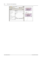
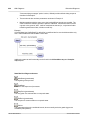
The Overview pane displays various tabs:
The Overview tab which displays an outline view of the currently active diagram
The Documentation tab which allows you to document your classes on a per-class
basis.
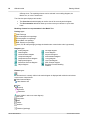
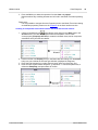
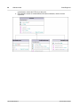
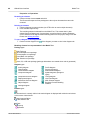
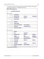
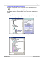
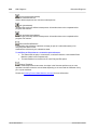
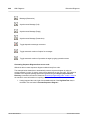
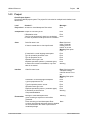
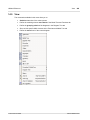
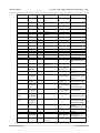
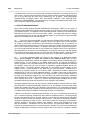
Modeling element icon representation in the Model Tree
Package types:
UML Package
Java namespace root package
C# namespace root package
Visual Basic root package
XML Schema root package
Java, C#, VB code package (package declarations are created when code is generated)
Diagram types:
Activity diagram
Class diagram
Communication diagram
Component diagram
Composite Structure diagram
Deployment diagram
Interaction Overview diagram
Object diagram
Package diagram
Profile diagram
Sequence diagram
State Machine diagram
Timing diagram
Use Case diagram
XML Schema diagram
Business Process Modeling
Notation
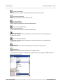
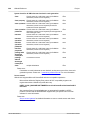
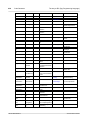
Element types:
An element that is currently visible in the active diagram is displayed with a blue dot at its base.
In this case a class element.
Class Instance/Object
Class instance slot
Class
Property
Operation
Parameter
Actor (visible in active use case diagram)
Use Case
Component
Node
Artifact
Interface
Relations (/package)
Altova UModel 2013
© 2012 Altova GmbH
UModel tutorial
Starting UModel
19
Constraints
© 2012 Altova GmbH
Altova UModel 2013
20
UModel tutorial
4.2
Use cases
Altova web site:
Use cases
UML Use Case diagrams
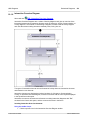
The aim of this tutorial section is to:
Add a new package to the project
Add a new Use Case diagram to the project
Add use case elements to the diagram, and define the dependencies amongst them
Align and size elements in the diagram tab.
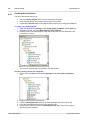
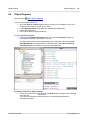
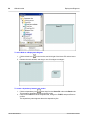
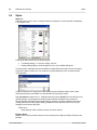
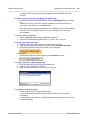
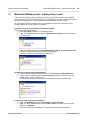
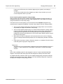
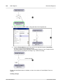
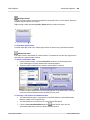
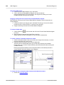
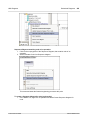
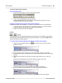
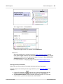
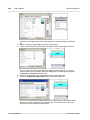
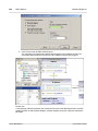
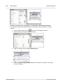
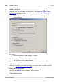
To add a new package to a project:
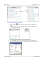
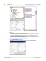
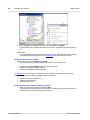
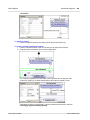
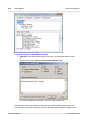
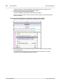
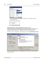
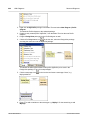
1. Right click the Root package in the Model Tree tab, and select New Element |
Package.
2. Enter the name of the new package e.g. Use Case View, and press Enter.
Please see Packages for more information on packages and their properties.
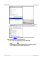
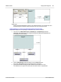
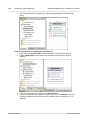
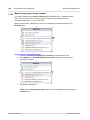
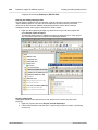
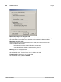
Adding a diagram to a package:
1. Right click the previously created Use Case View package.
2. Select New Diagram | UseCase Diagram.
Altova UModel 2013
© 2012 Altova GmbH
UModel tutorial
Use cases
21
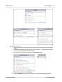
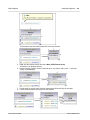
A Use Case diagram has now been added to the package in the Model Tree view, and
a diagram tab has been created in the diagram pane. A default name has been
provided automatically.
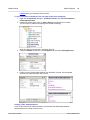
3. Double click the supplied name, in the Model Tree tab, change it to "Overview Account
Balance", and press Enter to confirm.
Please see Diagrams for more information on diagrams and their properties.
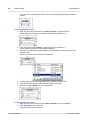
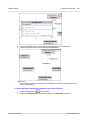
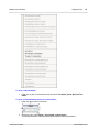
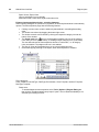
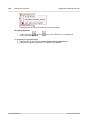
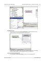
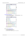
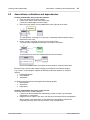
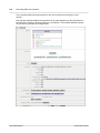
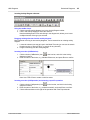
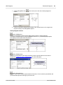
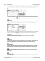
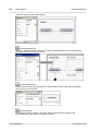
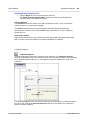
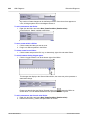
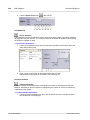
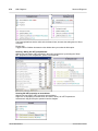
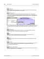
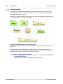
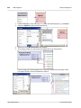
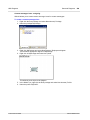
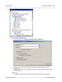
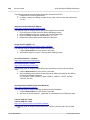
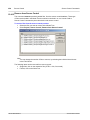
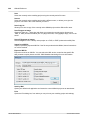
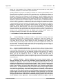
Adding Use case elements to the Use Case diagram:
1. Right click in the newly created diagram and select New | Actor.
The actor element is inserted at the click position.
2. Click the Use Case icon
in the icon bar and click in the diagram tab to insert the
element.
A UseCase1 element is inserted. Note that the element, and its name, are currently
selected, and that its properties are visible in the Properties tab.
© 2012 Altova GmbH
Altova UModel 2013
22
UModel tutorial
Use cases
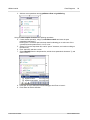
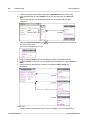
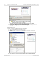
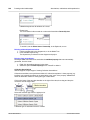
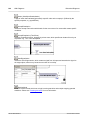
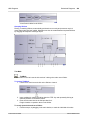
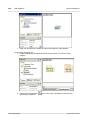
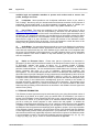
3. Change the title to "get account balance", press Enter to confirm. Double click the title if
it is deselected.
Note that the use case is automatically resized to adjust to the text length.
Model elements have various connection handles and other items used to manipulate
them.
Note: Use CTRL+Enter to create a multi-line use case name.
Manipulating UModel elements: handles and compartments
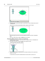
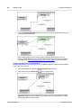
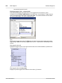
1. Double click the Actor1 text, of the Actor element, change the name to "Standard User"
and press Enter to confirm.
2. Place the mouse cursor over the "handle" to the right of the actor.
A tooltip containing "Association" appears.
3. Click the handle, drag the Association line to the right, and drop it on the "get account
balance" use case.
An association has now been created between the actor and the use case. The
Altova UModel 2013
© 2012 Altova GmbH
UModel tutorial
Use cases
23
association properties are also visible in the Properties tab. The new association has
been added to Model Tree under the Relations item of the Use Case View package.
4. Click the use case and drag it to the right to reposition it.
The association properties are visible on the association object.
5. Click the use case to select it, then click the collapse icon on the left hand edge of the
use case ellipse.
The extension points compartment is now hidden.
Please note:
A blue dot next to an element icon
, in the Model Tree tab, signifies
that the element is visible in the current diagram tab. Resizing the actor adjusts the text
field which can be multi line. A line break can be inserted into the text using
CTRL+Enter.
Finishing up the use case diagram:
Using the methods discussed above:
1. Click the Use Case icon in the icon bar and simultaneously hold down the CTRL
keyboard key.
2. Click at two different vertical positions in the diagram tab to add two more use cases,
then release the CTRL key.
3. Name the first use case "get account balance sum" and the second, "generate monthly
revenue report".
4. Click on the collapse icon of each use case to hide the extensions compartment.
© 2012 Altova GmbH
Altova UModel 2013
24
UModel tutorial
Use cases
5. Click the actor and use the association handle to create an association between
Standard user and "get account balance sum".
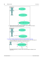
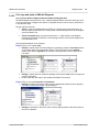
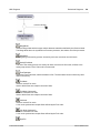
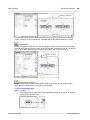
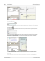
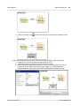
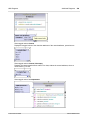
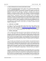
To create an "Include" dependency between use cases (creating a subcase):
1. Click the Include handle of the "get account balance sum" use case, at the bottom of
the ellipse, and drop the dependency on "get account balance".
An "include" dependency is created, and the include stereotype is displayed on the
dotted arrow.
Altova UModel 2013
© 2012 Altova GmbH
UModel tutorial
Use cases
25
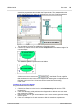
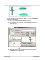
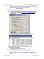
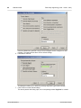
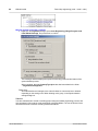
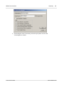
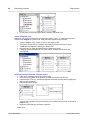
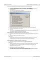
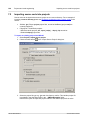
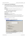
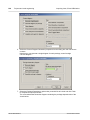
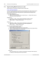
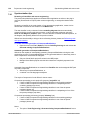
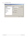
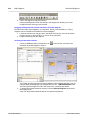
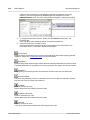
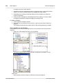
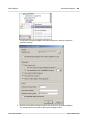
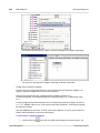
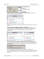
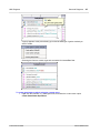
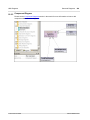
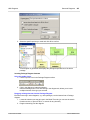
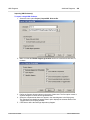
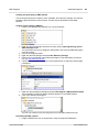
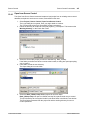
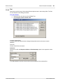
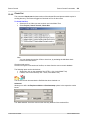
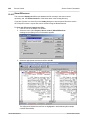
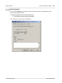
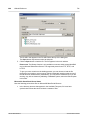
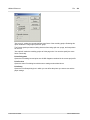
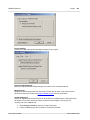
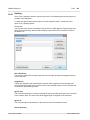
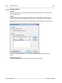
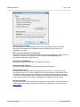
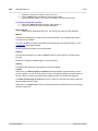
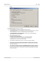
Inserting user-defined / customized actors:
The actor in the "generate monthly revenue report" use case is not a person, but an automated
batch job run by a Bank computer.
1. Insert an actor into the diagram using the Actor icon in the icon bar.
2. Rename the actor to Bank.
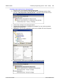
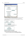
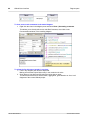
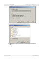
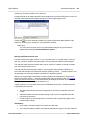
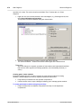
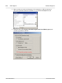
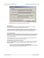
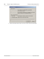
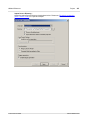
3. Move the cursor over to the Properties tab, and click the browse
icon next to the
"icon file name" entry.
4. Click the Browse icon to select the user-defined bitmap, Bank-PC.bmp.
5. Deselect the "Absolute Path" check box to make the path relative. Preview displays a
preview of the selected file in the dialog box.
6. Click OK to confirm the settings and insert the new actor.
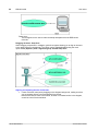
7. Move the new Bank actor to the right of the lowest use case.
8. Click the Association icon
in the icon bar and drag from the Bank actor to the
"generate monthly revenue report" use case.
This is an alternative method of creating an association.
© 2012 Altova GmbH
Altova UModel 2013
26
UModel tutorial
Use cases
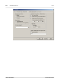
Please note:
The background color used to make the bitmap transparent has the RGB values
82.82.82.
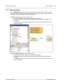
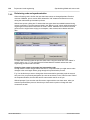
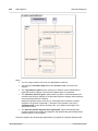
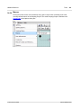
Dragging elements - Snap lines
When dragging components in a diagram, guide lines appear allowing you to align an element
to any other element in the diagram. This option can be enabled/disabled using the menu
option Tools | Options | View - Alignment group "Enable Snap lines".
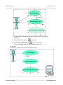
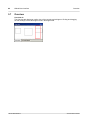
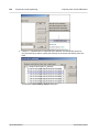
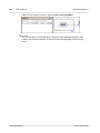
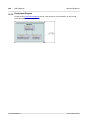
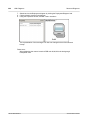
Aligning and adjusting the size of elements:
1. Create a selection marquee by dragging on the diagram background, making sure that
you encompass all three use cases starting from the top.
Note that the last use case to be marked, is shown in a dashed outline in the diagram,
as well as in the Overview window.
Altova UModel 2013
© 2012 Altova GmbH
UModel tutorial
Use cases
27
All use cases are selected, with the lowest being the basis for the following
adjustments.
2. Click the Make same size icon
in the title bar.
3. Click the Center Horizontally icon
to line up all the ovals.
The use case elements are all centered and of the same size.
Please note:
You can also use the CTRL key to select multiple elements.
© 2012 Altova GmbH
Altova UModel 2013
28
UModel tutorial
4.3
Class Diagrams
Altova web site:
Class Diagrams
UML Class diagrams
The aim of this tutorial section is to:
Add a new abstract class called Account, as well as attributes and operations
Create a composite association from Bank to Account
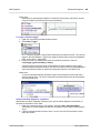
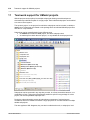
To open a different diagram in UModel:
1. Click the Diagram Tree tab.
2. Expand the Class Diagrams package to see its contents.
All class diagrams contained in the project are displayed.
3. Double click the
BankView Main diagram icon.
The Class diagram appears as a tab in the working area.
Please note:
You could of course, double click the Class diagram icon in the Model Tree tab below
the BankView package to achieve the same thing.
Two concrete classes with a composite association between them, are visible in the class
diagram.
Altova UModel 2013
© 2012 Altova GmbH
UModel tutorial
Class Diagrams
29
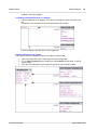
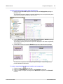
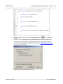
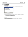
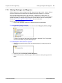
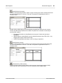
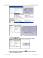
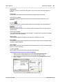
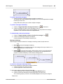
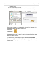
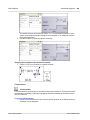
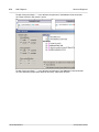
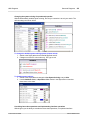
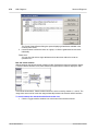
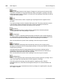
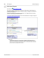
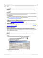
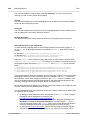
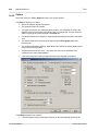
To add a new class and define it as abstract:
1. Click the class icon
in the icon bar, then click to the right of the Bank class to
insert it.
2. Change the Class1 name to e.g. "Account", press Enter to confirm, (double click the
name if it becomes deselected).
Note that the Properties tab displays the current class properties.
3. Click the "abstract" check box in the Properties pane to make the class abstract.
4. Click in the "code file name" text box, and enter Account.java to define the Java class.
© 2012 Altova GmbH
Altova UModel 2013
30
UModel tutorial
Class Diagrams
The class title is now displayed in italic, which is the identifying characteristic of abstract
classes.
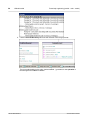
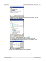
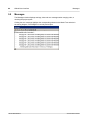
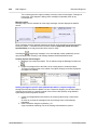
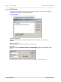
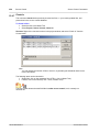
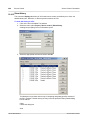
To add properties to a class:
1. Right click the Account class and select New | Property, or press the F7 key.
A default property "Property1" is inserted with stereotype identifiers << >>.
2. Enter the Property name "balance", and then add a colon character ":".
A drop-down list containing all valid types is displayed.
3. Enter the "f" character through the keyboard, and press Enter to insert the return value
datatype "float".
Please note that drop-down lists are case sensitive!
4. Continue on the same line by appending "=0" to define the default value.
5. Press the F7 keyboard key to add a second property to the class.
6. Enter Id: and select String from the drop-down list.
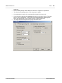
To add operations to a class:
1. Right click the Account class and select New | Operation, or press the F8 key.
2. Enter Account() as the constructor.
Using the method described above:
Altova UModel 2013
© 2012 Altova GmbH
UModel tutorial
Class Diagrams
31
3. Add two more operations namely getBalance:float and getId:String.
Using the autocomplete function while defining operations:
4. Create another operation, using F8, collectAccountInfo and enter the open
parenthesis character "(".
Entering the "i" character opens the drop-down list allowing you to select one of the
operation direction parameters: in, inout, or out.
5. Select "in" from the drop-down list, enter a "space" character, and continue editing on
the same line.
6 Enter "bankAPI" and then a colon.
7. Select IBankAPI from the drop-down list, add the close parenthesis character ")", and
enter a colon ":".
8. Press the "b" key to select the boolean datatype, then Enter to insert it.
9. Press Enter to end the definition.
© 2012 Altova GmbH
Altova UModel 2013
32
UModel tutorial
Class Diagrams
Please note:
Clicking the visibility icon to the left of an operation , or property , opens a
drop-down list enabling you to change the visibility status. Note that these visibilty icons
can be changed to the UML conformant symbols.
Deleting class properties and operations from a Class Diagram:
1. Press F8 then Enter, to add a default operation "Operation1" in the Account class.
2. Click Operation1 and press the Del. key to delete it.
A delete prompt appears asking if you want to delete the element from the project. Click
Yes to delete Operation1 from the class as well as from the project.
Please note:
If you only want to delete the operation from the class in the diagram, but not from the
project, press the CTRL+Del. key. You can also enable a prompt that queries you
when deleting objects, please see "Tools | Editing" for more information.
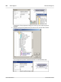
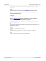
Finding (deleting) class properties and options from the Model Tree:
Properties and options can also be deleted directly from the Model Tree. To do this safely, it is
important to first find the correct property. Assuming you have inserted "Operation1" in the
Account class (press F8, then Enter to insert):
1. Right click Operation1 in the Account class.
2. Select the option "Select in Model Tree" or press F4.
The Operation1 item is now highlighted under Account in the Model Tree tab.
Altova UModel 2013
© 2012 Altova GmbH
UModel tutorial
Class Diagrams
33
3. Press the Del key to delete the operation from the class and project!
Note that almost any modeling element can be found in the Model Tree when pressing
F4.
Please note:
It is also possible to navigate from the Properties pane to the Model Tree when viewing
an attributes properties, please see: the Properties in the User Interface section.
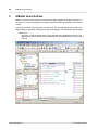
Creating an composition association between the Bank and Account classes:
1. Click the Composition icon
in the title bar, then drag from the Bank class to the
Account class. The class is highlighted when the association can be made.
A new property (Property1:Account) is created in the Bank class, and an composite
association arrow joins the two classes.
2. Double click the new Property1 entry in the Bank class and change it to "accounts",
being sure not to delete the Account type definition (displayed in teal/green).
3. Press the End keyboard key to place the text cursor at the end of the line, and
4. Enter the open square bracket character "[" and select "*" from the dropdown list, to
define the multiplicity, and press Enter to confirm.
© 2012 Altova GmbH
Altova UModel 2013
34
UModel tutorial
4.3.1
Creating derived classes
Class Diagrams
The aim of this tutorial section is to:
Add a new Class diagram called Account Hierarchy to the project
Insert existing classes, and create a new Savings account class
Create three derived classes of the abstract base class Account, using Generalizations
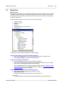
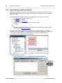
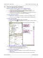
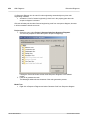
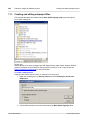
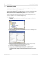
To create a new Class Diagram:
1. Right click the bankview package (under Design-phase | BankView | com | altova) in
the Model Tree tab, and select New Diagram | Class Diagram.
2. Double click the new ClassDiagram1 entry and rename it to "Account Hierarchy", and
press Enter to confirm.
The Account Hierarchy tab is now visible in the working area.
Inserting existing classes into a diagram:
1. Click the Account class in the bankview package (under com | altova | bankview),
and
2.
3.
4.
5.
Drag it into the Account Hierarchy tab.
Click the CheckingAccount class (of the same package) and drag it into the tab.
Place the class below and to the left of the Account class.
Use the same method to insert the CreditCardAccount class. Place it to the right of
the CheckingAccount class.
Altova UModel 2013
© 2012 Altova GmbH
UModel tutorial
Class Diagrams
35
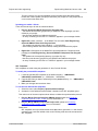
Adding a new class:
1. Right click the diagram background (to the right of CreditAccountClass) and select New
| Class.
A new class is automatically added to the correct package, i.e. bankview which contains
the current class diagram Account Hierarchy.
2. Double click the class name and change it to SavingsAccount.
3. Press the F7 key to add a new property.
4. Enter "interestRate", then a colon, and press "f" to select the float datatype from the
© 2012 Altova GmbH
Altova UModel 2013
36
UModel tutorial
Class Diagrams
dropdown list and press Enter twice to select and confirm the entry.
5. Press F8 and add the operation/constructor SavingsAccount().
6. Use the same method, F8, to add the operation getMinimumBalance:float.
7. Click in the "code file name" text box, in the Properties tab, and enter
SavingsAccount.java to define the Java code class.
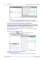
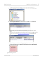
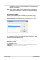
Reusing/copying existing Properties/Operations:
Properties and operations can be directly copied, or moved, from one class to another. This can
be achieved using drag and drop, as well as the standard keyboard shortcuts:
within a class in the diagram tab
between different classes in the diagram tab
in the Model Tree view
between different UML diagrams, by dropping the copied data onto a different diagram
tab.
Please see "Cut, copy and paste in UModel Diagrams" for more information.
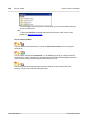
1. Expand the Account class in the Model Tree.
2. Right click the collectAccountInfo operation and select Copy.
Altova UModel 2013
© 2012 Altova GmbH
UModel tutorial
Class Diagrams
37
3. Right click the SavingsAccount class in the Model Tree and select Paste.
The operation is copied into the SavingsAccount class, which is automatically expanded
to display the new operation.
The new operation is now also visible in the SavingsAccount class in the Class
Diagram.
Please note:
You can use the Copy/Paste keyboard shortcuts (CTRL C, or V), as well as drag and
drop in the Model Tree to achieve the same effect. You might have to disable the sort
options to drop the operation between specific items.
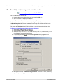
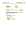
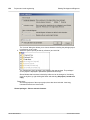
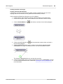
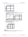
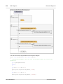
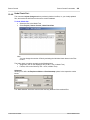
Creating derived classes - Generalization/Specialization:
At this point the class diagram contains the abstract class, Account, as well as three specific
Account classes. We now want to define, or create a generalization/specialization relationship
between Account and the specific classes i.e. to create three derived concrete classes.
1. Click the Generalization icon
in the icon bar and hold down the CTRL key.
2. Drag from CreditCardAccount (the class in the middle) and drop on the Account class.
3. Drag from the CheckingAccount class and drop the arrowhead of the previously
created generalization.
4. Drag from the SavingsAccount class and drop the arrowhead of the previously created
© 2012 Altova GmbH
Altova UModel 2013
38
UModel tutorial
Class Diagrams
generalization: release the CTRL key at this point.
5. Generalization arrows are created between the three subclasses, and the Account
superclass.
Altova UModel 2013
© 2012 Altova GmbH
UModel tutorial
4.4
Object Diagrams
39
Object Diagrams
Altova web site:
UML Object diagrams
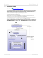
The aim of this tutorial section is to:
Show how class and object diagrams can be combined in one diagram, to give you a
snapshot of the objects at a given point of time
Create Objects/Instances and define the relationships between them
Format association/links
Enter real-life data into objects/instances
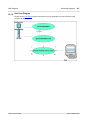
To open the Object diagram:
1. Double click the Sample Accounts diagram icon under the bankview package (or
under Object Diagrams in the Diagram Tree tab).
The Bank class and two related objects/instances are displayed in the object diagram.
AltovaBank:Bank is the object/instance of the Bank class, while John's checking:
CheckingAccount is an instance of the class CheckingAccount.
Inserting a class into an Object diagram:
Click the Account class icon
in the Model Tree, and drag it into the "Sample
Accounts" tab.
The composite association defined previously, in BankView Main diagram, is
automatically created.
© 2012 Altova GmbH
Altova UModel 2013
40
UModel tutorial
Object Diagrams
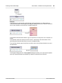
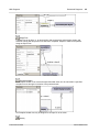
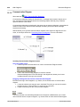
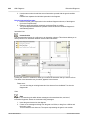
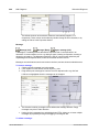
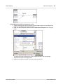
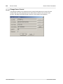
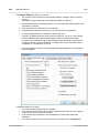
To add a new object/instance by selecting its type:
1. Click the InstanceSpecification icon
in the icon bar, then click under the John's
Checking object in the diagram tab.
2. Change the name of the instance to John's Credit, and press Enter.
While the instance is active, all its properties are visible in the Properties tab.
3. Click the classifier combo box and select the entry CreditCardAccount from the
drop-down list.
Note that right clicking an instance specification and selecting Show/Hide Node
Altova UModel 2013
© 2012 Altova GmbH
UModel tutorial
Object Diagrams
41
content allows you show/hide object content.
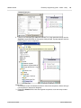
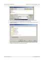
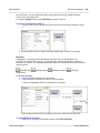
To add a new object in the Model Tree view (then insert it into a diagram):
1. Right click the bankview package in the Model Tree tab, and select New element |
InstanceSpecification.
2. Change the default object name to John's Saving, and press Enter to confirm.
The new object is added to the package and sorted accordingly.
While the object is still selected in the Model Tree tab,
3. Click the classifier combo box, in the Properties tab, and select SavingsAccount.
4. Drag the John's Saving object/instance from the Model Tree tab, into the Sample
Accounts tab, placing it below John's credit.
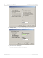
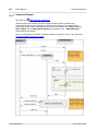
Creating "links" between objects:
Links are the instances of class associations, and describe the relationships between
objects/instances at a fixed moment in time.
© 2012 Altova GmbH
Altova UModel 2013
42
UModel tutorial
Object Diagrams
1. Click the existing link (association) between the AltovaBank and John's Checking.
2. In the Properties tab, click the classifier combo box and select the entry Account Bank.
The link now changes to a composite association, in accordance with the class
definitions.
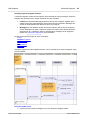
3.
Click the InstanceSpecification icon
the John's Credit class.
The cursor now appears as a + sign.
in the icon bar, and position the cursor over
4. Drag from John's Credit object to AltovaBank to create a link between the two.
5. Use the classifier combo box in the Properties tab to change the link type to Account Bank.
6. Use the method outlined above to create a link between John's Saving and
AltovaBank.
Please note:
Changes made to the association type in any class diagram, are now automatically
Altova UModel 2013
© 2012 Altova GmbH
UModel tutorial
Object Diagrams
43
updated in the object diagram.
Formatting association/link lines in a diagram:
1. Click the lowest link in the diagram, if not active, and drag the corner connector to the
left.
This allows you to reposition the line both horizontally and vertically.
Use this method to reposition links in the diagram tab.
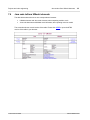
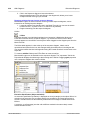
Entering sample data into objects:
The instance value of an Attribute/Property in an object is called a slot.
1.
2.
3.
Click in the respective slots of each object and enter sample data.
E.g. in John's Checking object, double click in the balance slot and enter 11,975.00
as the balance.
Fill in the rest of the data to give yourself an idea of the current instance state.
© 2012 Altova GmbH
Altova UModel 2013
44
UModel tutorial
4.5
Component Diagrams
Component Diagrams
The aim of this tutorial section is to:
Show how to insert classes into a component diagram
Create realization dependencies between the classes and the BankView component
Show how to change line properties
Insert components into a component diagram, and create usage dependencies to an
interface
To open the component diagram:
1. Click the Diagram Tree tab, expand the Component Diagrams component and double
click the "BankView realization" diagram icon.
The "BankView realization" component diagram is displayed.
2. Switch back to the Model Tree tab by clicking that tab.
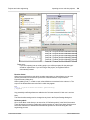
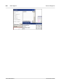
To insert (existing) classes into a component diagram:
1. Locate the SavingsAccount class
2. Drag it into the component diagram.
The class is displayed with all its compartments.
Altova UModel 2013
under the bankview package.
© 2012 Altova GmbH
UModel tutorial
Component Diagrams
45
3. Click both collapse icons to end up with the only the class name compartment.
4. Use the same method to insert the abstract class Account.
Please note:
The package containing the inserted class, is displayed in the name compartment in the
form "from bankview".
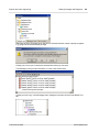
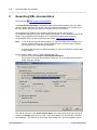
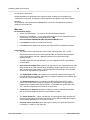
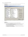
To create Realization dependencies between a class and component:
1. Click the Realization icon
in the icon bar.
2. Drag from SavingsAccount, and drop the arrow on the BankView component.
© 2012 Altova GmbH
Altova UModel 2013
46
UModel tutorial
Component Diagrams
3. Click the ComponentRealization handle of the Account class (at the base), and drop it
on the BankView component.
Both of these methods can be used to create realization dependencies. There is
another method that allows you to create realization dependencies solely in the Model
Tree, please see Round-trip engineering (code - model - code) for more information.
Changing (Realization) line characteristics:
Clicking a dependency or any other type of line in a UModel diagram, activates the line drawing
icons in the Layout icon bar.
1.
Click the realization line between SavingsAccount and BankView.
2.
Click the line type icon Direct line
in the Layout toolbar.
The line properties are immediately altered. Lines have small icons along them called
waypoints. Waypoints can be clicked and moved to alter line characteristics. Change
the line properties to suit your needs.
Altova UModel 2013
© 2012 Altova GmbH
UModel tutorial
Component Diagrams
47
Inserting components and creating usage dependencies:
1. Double click the Overview diagram icon directly under the Design-phase package in
the Model Tree.
The Overview component diagram is opened and displays the currently defined system
dependencies between components and interfaces.
2. Click the BankView GUI component under the Component View | BankView package
in the Model Tree, and drag it into the Overview diagram tab.
The package containing the inserted component is displayed in the name compartment,
"from BankView".
3. Use the same method to insert the BankView component under the same package.
The BankView component is the component produced by the "forward-engineering"
process described in this tutorial.
To create a usage dependency between interfaces and components:
1. Click the Usage icon
in the icon bar.
2. Drag from the BankView GUI component to the BankView component.
3. Click the Usage icon again, and drag from the BankView component to the IBankAPI
interface.
© 2012 Altova GmbH
Altova UModel 2013
48
UModel tutorial
Component Diagrams
The usage dependency (<<use>>) connects a client element to a supplier element. In
this case the IBankInterfaceAPI interface uses the services of components BankView
and BankView GUI.
Altova UModel 2013
© 2012 Altova GmbH
UModel tutorial
4.6
Deployment Diagrams
49
Deployment Diagrams
The aim of this tutorial section is to:
Show the artifact manifestation of components
Add a new node and dependency to a Deployment diagram
Add artifacts to a node and create relationships between them
To open the Deployment (Artifacts) diagram:
1. Click the Model Tree tab, expand the Deployment View diagram package, then double
click the Artifacts icon.
This diagram shows the manifestation of the Bank API client and the BankView
components, to their respective compiled Java .jar files.
To open the Deployment diagram:
1. Double click the Deployment icon under the Deployment View package.
The Deployment diagram is opened and displays the physical architecture of the
system, which currently only comprises of the Home PC node.
© 2012 Altova GmbH
Altova UModel 2013
50
UModel tutorial
Deployment Diagrams
To add a Node to a Deployment diagram:
1. Click the Node icon
in the icon bar, and click right of the Home PC node to insert
it.
2. Rename the node to Bank, and drag on one of its edges to enlarge it.
To create a dependency between two nodes:
1. Click the dependency icon
, then drag from the Home PC node to the Bank node.
This creates a dependency between the two nodes.
2. Click into the name field of the Properties tab, change it to TCP/IP, and press Enter to
confirm.
The dependency name appears above the dependency line.
Altova UModel 2013
© 2012 Altova GmbH
UModel tutorial
Deployment Diagrams
51
Please note:
Having clicked the dependency arrow (or any named elements), you can also enter text
directly through the keyboard, without having to first click into the name field.
Adding artifacts to a node and creating dependencies between them:
Expand the Deployment View package, in the Model Tree, to see its contents:
1. Click each of the BankAddresses.ini, BankAPI.jar and BankView.jar artifacts
individually, and place them on the diagram background (Deployment dependencies
are displayed for each artifact).
2. Click the BankView.jar artifact and drag it onto the Home PC node.
The node is highlighted when the drop action will be successful.
3. Use the same method to drag the other artifacts onto the Home PC node.
The artifacts are now part of the node and move with it when it is repositioned.
© 2012 Altova GmbH
Altova UModel 2013
52
UModel tutorial
Deployment Diagrams
4. Click the Dependency icon
in the icon bar, and hold down the CTRL key.
5. Drag from the BankView.jar artifact to the BankAddresses.ini artifact; still holding
down the CTRL key.
6. Drag from the BankView.jar artifact to the BankAPI.jar artifact.
Please note:
Dragging an artifact out of a node onto the diagram background, automatically creates
a Deployment dependency.
To delete an artifact from a node and the project:
Click the artifact you want to delete and press the Del keyboard key.
The artifact and any dependencies are deleted from the node as well as the project.
To remove an artifact from a node and its diagram:
1. Use drag and drop to place the artifact onto the diagram background.
2. Hold down the CTRL key and press Del.
The artifact and any dependencies are deleted from the current diagram and not from
the project.
To create operations / properties, or nesting artifacts:
1. Right click the artifact in the Model Tree.
2. Select the appropriate action from the context menu, e.g. New Element | Operation, |
Property, or | Artifact.
The new element will appear below the selected artifact in the Model Tree.
Altova UModel 2013
© 2012 Altova GmbH
UModel tutorial
4.7
Round-trip engineering (model - code - model)
53
Round-trip engineering (model - code - model)
Altova web site:
UML code generation and UML Round-trip engineering
The aim of this tutorial section is to:
Perform a project syntax check
Generate project code
Add a new method external code i.e. to the SavingsAccount class
Synchronize the UModel model new code with the model
Packages and Code / model synchronization:
Code can be merged/synchronized at different levels:
Project, Root package level (menu item)
Package level (multiple package selection / generation is possible)
Class level (multiple class selection / generation is possible)
Component level
The BankView realization diagram, depicts how the BankView component is realized by its six
constituent classes. This is the component that is produced when the forward-engineering
section of the tutorial is complete.
To be able to produce code:
The component must be realized by one or more classes.
The component must have a physical location, i.e. directory, assigned to it. The
generated code is then placed in this directory.
Components must be individually set to be included in the code engineering process.
A Java, C#, or VB namespace root package must be defined.
Please note:
The Java namespace root has been set on the Design-phase | BankView | com
package in the Model Tree.
Java, C# or VB code can be combined in one project and are automatically handled
during the round-trip engineering process. The Bank_MultiLanguage.ump file in the ...\
UModelExamples folder is an example of a project for Java and C# types of code.
To define a code generation target directory:
1. Double click the
Overview icon under the Design-phase package to switch into the
component overview.
2. Click the BankView component, in the diagram, and note the current settings in the
Properties tab.
3. Click the browse button
, to the right of the directory field.
4. Enter/select the target directory in the dialog box (the supplied example is defined as
InstallationDir\UModelExamples\Tutorial\umlcode\bankview), or click the "Make
New Folder" button to create a new folder.
The path now appears in the directory field.
© 2012 Altova GmbH
Altova UModel 2013
54
UModel tutorial
Round-trip engineering (model - code - model)
Please note:
UModel Java usually follows the convention of creating code in directories according to
their namespace e.g. ...\code\namespace1\C1.java.
If you want to use this directory naming convention for C# and VB .NET, select the
menu option Tools | Options | Code Engineering and select the relevant option in the
"Use namespace for code file path" group.
To include/exclude components from code generation:
1. Click the BankView GUI component.
2. Uncheck the "use for code engineering" check box (if not already unchecked).
Altova UModel 2013
© 2012 Altova GmbH
UModel tutorial
Round-trip engineering (model - code - model)
55
Checking project syntax prior to code generation:
1. Select the menu option Project | Check project syntax.
2. A syntax check is performed, and messages appear in the Messages window, "Bank
API-client: code project file or directory not set" - "IBankAPI: code file name not set".
3. Click the first message in the messages window.
4. The Bank API client package is highlighted in the Model Tree view, with its properties
visible in the Properties tab.
5. Uncheck the "use for code engineering" check box for the Bank API client component.
6. Check the project syntax again using Project | Check project syntax.
© 2012 Altova GmbH
Altova UModel 2013
56
UModel tutorial
Round-trip engineering (model - code - model)
No errors are reported this time around. We can now generate program code for this
project. Please see Check Project syntax for more information.
To generate project code:
1. Click the BankView package to select it.
2. Select the menu option Project | Merge Program Code from UModel project.
3. Select your synchronization options from the dialog box, and press OK to proceed (no
changes needed for the tutorial; see "Merge Program Code from UModel project" for
more information).
The message pane displays the outcome of the code generation process.
4. Navigate to the target directory.
Six .Java files have been created for the project.
Synchronizing the UModel model having updated Java code externally:
1. Open the SavingsAccount.java file in the text editor of your choice, XMLSpy for
example.
2. Add the new method to the generated code "public float getInterestRate() {}", and
save the file.
Altova UModel 2013
© 2012 Altova GmbH
UModel tutorial
Round-trip engineering (model - code - model)
57
3. Switch to UModel and right click the SavingsAccount class
under the BankView
package.
4. Select the option Code Engineering | Merge UModel Class from Program Code.
This opens the Synchronization Settings dialog box with the "Model from Code" tab
being active. No changes are needed for the tutorial; see "Merge UModel project from
code" for more information)
5. Click OK to merge the model from the code.
© 2012 Altova GmbH
Altova UModel 2013
58
UModel tutorial
Round-trip engineering (model - code - model)
6. Click the Account Hierarchy tab to see the outcome of the merge process.
The new method added to the code, (getInterestRate...) generates a new operation in
the SavingsAccount class of UModel.
Altova UModel 2013
© 2012 Altova GmbH
UModel tutorial
4.8
Round-trip engineering (code - model - code)
59
Round-trip engineering (code - model - code)
Altova web site:
Reverse engineering - Java, C#, VB .NET code
The aim of this tutorial section is to:
Import a directory containing Java code generated by XMLSpy
Add a new class to the project in UModel
Merge to the program code from a UModel package
The files used in this example are available as the OrgChart.zip file under
...\UModelExamples folder of your installation. Please unzip the OrgChart.zip file into the
...\UModelExamples folder before you start this section.
This creates the OrgChart directory which will then be used to import the existing code.
To Reverse engineer/import existing code from a directory:
1. Select File | New to create a new project.
2. Select Project | Import source directory.
3. Select the C# (1.2, 2.0, 3.0, or 4.0), Java version (1.4, or 5.0), or VB version (7.1, 8.0,
or 9.0) that the source code conforms to.
4. Click the Browse button
and select the OrgChart directory supplied in the
...\UModelExamples folder.
5. Making sure that the "Enable diagram generation" check box is active, select any
specific import settings you need, and click Next.
© 2012 Altova GmbH
Altova UModel 2013
60
UModel tutorial
Round-trip engineering (code - model - code)
Note that UModel can generate a single overview diagram and/or a diagram for each
package. The settings show above are the default settings.
6. Click Next to continue.
This dialog box allows you to define the package dependency generation settings.
7. Click Finish to use the default settings.
The data is parsed while being input, and a new package called "OrgChart" is created.
Altova UModel 2013
© 2012 Altova GmbH
UModel tutorial
Round-trip engineering (code - model - code)
61
8. Expand the new package and keep expanding the sub packages until you get to the
OrgChart package (com | OrgChart).
9. Double click the "Content of OrgChart" diagram icon
.
The collapsed classes that make up OrgChart are displayed in the main tab.
The current window/view is shown by the red box in the Overview window, which
occupies an empty area of the diagram.
10. Click the red box and drag it down to the centre of the window.
© 2012 Altova GmbH
Altova UModel 2013
62
UModel tutorial
Round-trip engineering (code - model - code)
Please note:
You could also select the Project | Import source project option and select the
Borland JBuilder OrgChart.jpx project file to import the project created by XMLSpy.
Round-trip engineering and relationships between modeling elements:
When updating model from code, associations between modeling elements are automatically
displayed, if the option Editing | Automatically create Associations has been activated in the
Tools | Options dialog box. Associations are displayed for those elements where the attributes
type is set, and the referenced "type" modeling element is in the same diagram.
InterfaceRealizations as well as Generalizations are all automatically shown in the diagram
when updating model from code.
Adding a new class to the OrgChart diagram:
1. Click the Class icon
in the icon bar and click to insert a new class.
2. Add a new Class called CompanyType.
3. Add new operations to the class using the F8 shortcut key:
e.g. CompanyType(), getCompanyType():String, setCompanyType():String.
Making the new class available for code generation:
While the CompanyType class is active,
1. Click into the "code file name" field and enter the Java file name of the new class
Altova UModel 2013
© 2012 Altova GmbH
UModel tutorial
Round-trip engineering (code - model - code)
63
CompanyType.java.
2. Click the new CompanyType class in the Model Tree, drag upwards and drop onto the
OrgChart component below the Component View package. A popup appears when the
mouse pointer is over a component.
Please note:
This method creates a Realization between a class and a component, without having to
use component or deployment diagrams.
3. Expand the Relations item below the Orgchart component, to see the newly created
realization.
© 2012 Altova GmbH
Altova UModel 2013
64
UModel tutorial
Round-trip engineering (code - model - code)
Merging program code from a package:
1. Right click the OrgChart package, select Code Engineering | Merge Program code
from UModel Package, and press Enter to confirm.
The messages window displays the syntax checks being performed and status of the
synchronization process.
When complete, the new CompanyType.java class has been added to the folder
...\OrgChart\com\OrgChart\.
Please note:
All method bodies and changes to the code will either be commented out or deleted,
depending on the setting in the "When deleting code" group, in the Synchronization
settings dialog box.
That's it!
You have learned how to create a modeling project using the forward engineering process, and
also completed a full round-trip code engineering cycle with UModel. The rest of this document
describes how best to achieve modeling results with UModel.
Altova UModel 2013
© 2012 Altova GmbH
Chapter 5
UModel User Interface
66
UModel User Interface
5
UModel User Interface
UModel consists of series of panes on the left and a larger diagram tab at right. The panes at
left allow you to view and navigate your UModel project from differing viewpoints, and edit data
directly.
The panes are Model Tree, Properties, and Overview. The working/viewing area at right is the
UModel Diagram tab which currently shows the Class Diagram of the BankView Main package.
Please note:
All panes, as well as diagram tabs, can be searched using the Find combo box in the
Main toolbar, which contains the text "account" in the screenshot below, or by pressing
CTRL+F.
Altova UModel 2013
© 2012 Altova GmbH
UModel User Interface
5.1
Model Tree
67
Model Tree
Model Tree tab
The Model Tree tab allows you to manipulate model items directly in the Model Tree, as well as
navigate/view specific items in the Design tab. Right clicking an item opens the context menu,
from which specific commands can be selected. The contents of the context menu depend on
the item that you select.
Model elements in the Model Tree pane can be directly manipulated:
Added / inserted
Copied or moved
Deleted
Renamed
Sorted according to several criteria
Constrained
In the Model Tree tab, each folder symbol is a UML package!
Adding a new package (or any other modeling element):
1. Right click the folder that you want the new package/element to appear under.
2. Select New | Package (or respective model Element).
Copying or moving model elements:
1. Use the standard windows Cut, Copy or Paste commands or,
2. Drag model elements to different packages. Dragging an elements moves it. Holding
down CTRL a and dragging an element creates a copy.
When dragging elements a message might appear stating that select "No sort" needs
to be activated to allow you to complete the action. Please see "Cut, copy and paste in
UModel Diagrams" for more information.
Sorting elements in the Model Tree (activating no sort):
1. Right click the empty background of the Model Tree tab.
2. Select Sort | No sort.
Elements can now be positioned anywhere in the Model Tree.
Please note:
The Sort popup menu also allows you to individually define the sort properties of
© 2012 Altova GmbH
Altova UModel 2013
68
UModel User Interface
Model Tree
Properties and Operations.
Renaming an element:
1. Double click the element name and edit it.
The Root and Component View packages are the only two elements that cannot be
renamed.
Deleting an element:
1. Click the element you want to delete (use CTRL+click to mark multiple elements).
2. Press the Del. keyboard key.
The modeling element is deleted from the Model Tree. This means that it is also
deleted from the Diagram tab, if present there, as well as from the project. Elements
can be deleted from a diagram without deleting them from the project, using CTRL+Del.
Please see deleting elements.
To open a diagram in the Diagram tab:
1. Double click the diagram icon
of the diagram you want to view in the diagram tab.
Modeling element icon representation in the Model Tree
Package types:
UML Package
Java namespace root package
C# namespace root package
Visual Basic root package
XML Schema root package
Java, C#, or VB code package (package declarations are created when code is generated)
Diagram types:
Activity diagram
Class diagram
Communication diagram
Component diagram
Composite Structure diagram
Deployment diagram
Interaction Overview diagram
Object diagram
Profile diagram
Sequence diagram
State Machine diagram
SysML diagrams (9 diagram
types)
Timing diagram
Use Case diagram
XML Schema diagram
Business Process Modeling
Notation
Package diagram
Element types:
An element that is currently visible in the active diagram is displayed with a blue dot at its base.
In this case a class element.
Class Instance/Object
Class instance slot
Class
Property
Operation
Altova UModel 2013
© 2012 Altova GmbH
UModel User Interface
Model Tree
69
Parameter
Actor (visible in active use case diagram)
Use Case
Component
Node
Artifact
Interface
Relations (/package)
Constraints
Opening / expanding packages in the Model Tree view:
There are two methods available to open packages in the tree view; one opens all packages
and sub packages, the other opens the current package.
Click the package you want to open and:
Press the * key to open the current package and all sub packages
Press the + key to open the current package.
To collapse the packages, press the - keyboard key. To collapse all packages click the
Root package and press -.
Note that you can use the standard keyboard keys, or the numeric keypad keys to
achieve this.
To find modeling elements in Diagram tab(s):
While navigating the elements in the Model Tree, you might want to see where, or if, the
element is actually present in a model diagram. There are two methods to find elements:
1. Right click the element you want to see in the Model Tree tab, and select:
Show element in active diagram - to find it in the same type of diagram tab
Show element in all diagrams - if currently active diagram differs from selected
model element.
To generate a list of elements not used in any diagram:
1. Right click the package you would like to inspect.
2. Select the menu option "List elements not used in any diagram.
A list of unused element appears in the Messages pane. The list in parenthesis,
displays the specific elements which have been selected to appear in the unused list,
please see the View tab in Reference section under, Tools | Options for more
information.
To locate the missing elements in the Model Tree:
Click the element name in the Messages pane.
Please note:
The unused elements are displayed for the current package and its sub packages.
© 2012 Altova GmbH
Altova UModel 2013
70
UModel User Interface
Model Tree
Packages in the Model Tree tab:
Only the Root and Component packages are visible on startup, i.e. when no project is currently
loaded.
Packages can be created, or deleted at any position in the Model Tree
Packages are the containers for all other UML modeling elements, use case diagrams
etc.
Packages/contents can be moved/copied to other packages in the Model Tree (as well
as into valid model diagrams in the diagram tab)
Packages and their contents can be sorted according to several criteria
Packages can be placed within other packages
Packages can be used as the source, or target elements, when generating or
synchronizing code
Generating/merging code:
UModel allows you to generate, or merge program code directly from the Model Tree, please
see: Synchronizing Model and source code for more information.
Constraining UML elements:
Constraints can be defined for most model elements in UModel. Please note that they are not
checked by the syntax checker, as constraints are not part of the Java code generation
process.
To constrain an element (Model Tree):
1. Right click the element you want to constrain, and select New | Constraint.
2. Enter the name of constraint and press Enter.
3. Click in the "specification" field of the Properties tab, and enter the constraint e.g. name
length > 10.
To constrain an element in UML diagrams:
1. Double click the specific element to be able to edit it.
2. Add the constraint between curly braces e.g. interestRate:float #{interestRate >=0}.
To assign constraints to multiple modeling elements:
1. Right click the "constrained elements" field in the Properties tab.
2. Select "Add element to constrained elements".
This opens the "Select Elements to be Constrained" dialog box.
3. Select the specific element you want to assign the current constraint to.
The "constrained element" field contains the names of the modeling elements it has
been assigned to. The image above, shows that Constraint1 has been assigned to the
bankview and com packages.
Altova UModel 2013
© 2012 Altova GmbH
UModel User Interface
5.2
Diagram Tree
71
Diagram Tree
Diagram Tree tab
This tab displays the currently available UModel diagrams in two ways:
Grouped by diagram type, sorted alphabetically
As an alphabetical list of all project diagrams
Please note:
Diagrams can be added to, or deleted from, the Diagram Tree tab by right clicking and
selecting the requisite command.
To open a diagram in the Diagram tab:
Double click the diagram you want to view in the diagram tab.
To view all Diagrams within their respective model groups:
Right click in the pane, and activate the "Group diagram by diagram type" option.
Diagrams are grouped alphabetically within their group.
To view all Diagram types in list form (alphabetically):
Right click in the pane, and deactivate the "Group diagram by diagram type" option.
© 2012 Altova GmbH
Altova UModel 2013
72
UModel User Interface
Diagram Tree
All Diagrams are shown in an alphabetically sorted list.
Altova UModel 2013
© 2012 Altova GmbH
UModel User Interface
5.3
Favorites
73
Favorites
Favorites tab
Use this tab as a user-defined repository, or library, for all types of named UML elements i.e.
classes, objects, associations etc. but not ProfileApplication or Generalization dependencies.
This allows you to create your personal pick-list of modeling elements for quick access.
The contents of the Favorites tab are automatically saved with each project file. Select the
menu option Tools | Options, File tab and click the "Load and save with project file" check box
to change this setting.
To add an existing modeling element to the Favorites tab:
1. Right click an element in the Model Tree tab, or in the diagram working area.
2. Select the menu item "Add to Favorites".
3. Click the Favorites tab to see the element.
The element appears in the Favorites tab is a view of an existing element, i.e. it is not a
copy or clone!
To add a NEW element to the Favorites tab:
1. Right click a previously added package, to which you want to add the element.
2. Select New | "modeling element" from the context menu, where "modeling element"
is a class, component, or any other modeling element available in the context menu.
New elements are added to the same element/package in the project, and are therefore
also visible in the Model Tree tab.
To REMOVE an element from the Favorites tab:
1. Right click the same element/package that you added to Favorites.
2. Select Remove from Favorites.
Please note:
You can add and remove elements added to the Favorites tab, from the Favorites tab,
as well as the Model Tree tab.
Deleting elements from the Favorites tab:
1. Right click the element you want to delete, and press the Del key.
A message box appears, informing you that the element will be deleted from the
project.
2. Click OK if you want to delete it from the project.
3. Click Cancel to retain it, and use the Remove method described above, to delete it
from the Favorites tab.
© 2012 Altova GmbH
Altova UModel 2013
74
UModel User Interface
5.4
Properties
Properties
Properties tab
The Properties tab displays the UML properties of the currently active element.
Clicking any model element in any of the supplied views, or tabs, displays its
properties.
Once visible, model properties can be changed, or completed, by entering data, or
selecting various options in the tab.
Selected properties can also be located in the diagram tabs by selecting Show in Active
Diagram from the context menu.
Select in Model Tree
Clicking an attribute in a class diagram displays its properties in the Properties tab. To
navigate/find it in the Model Tree:
1. Right click the type entry of the attribute in the Properties tab.
2. Click the "Select in Model Tree" popup.
The IBankAPI interface is now visible in the Model Tree.
Altova UModel 2013
© 2012 Altova GmbH
UModel User Interface
© 2012 Altova GmbH
Properties
75
Altova UModel 2013
76
UModel User Interface
5.5
Styles
Styles
Styles tab
The Styles tab is used to view, or change attributes of diagrams, or elements that are displayed
in the diagram view.
These style attributes fall into two general groups:
Formatting settings; i.e. font size, weight, color etc.
Display settings/options; show background color, grid, visibility settings etc.
The Styles tab is subdivided into several different categories/sections which can be selected by
clicking the "Styles" combo box. The combo box contents depends on the currently selected
model element.
Clicking an element in a diagram tab automatically selects the Element Style context, while
clicking and element in the Model Tree tab selects the Project Style context.
Style precedence is bottom-up, i.e. changes made at the more specific level override the more
general settings. E.g changes (to an object) made at the Element Style level override the
current Element Family and Project Styles settings. However, selecting a different object and
changing the Element Family Styles setting, updates all other objects except for the one just
changed at the Element Style level.
Please note:
Style changes made to model elements can all be undone!
Element Styles:
Applies to the currently selected element in the currently active diagram. Multiple selections are
possible.
Altova UModel 2013
© 2012 Altova GmbH
UModel User Interface
Styles
77
Styles of Elements with this Stereotype:
Applies to the currently selected stereotype class in the diagram it has been defined, please
see User-defined stereotype styles.
Element Family Styles:
Applies to all elements of the same type i.e. of the selected Element Family. E.g. you want to
have all Component elements colored in aqua. All components in the Component and
Deployment diagrams are now in aqua.
Node / Line Styles:
"Node" applies to all rectangular objects.
"Lines" applies to all connectors: association, dependency, realization lines etc. for the whole
project.
Project Styles:
Project Styles apply to the current UModel Project in its entirety (e.g. you want to change the
default Arial font to Times New Roman for all text in all diagrams of the project).
Diagram Styles:
These styles only becomes available when you click/select a diagram background. Changing
settings here, only affects the single UML diagram for which the settings are defined in the
project.
To change settings for all diagrams of a project:
1. Click in the respective diagram,
2. Select the Project Styles entry in the combo box, and scroll to the bottom of the tab.
3. Select one of the Diag.yyy options e.g. Diag. Background color.
This then changes the background color of all diagrams in the current project.
Styles display when multiple elements are selected:
If multiple elements are selected in the diagram pane, then all different style values are
displayed in the respective field. In the screenshot below, Class1 and Class2 have been
selected.
The fill Color field displays the values for each of the elements, i.e. aqua and silver.
Displaying cascading styles:
If a style is overridden at a more specific level, a small red triangle appears in the respective
field in the styles tab.
Placing the mouse pointer over the field displays a popup which indicates the style precedence.
© 2012 Altova GmbH
Altova UModel 2013
78
UModel User Interface
Styles
E.g.
The Enumeration, Package and Profile elements all have default fill color settings defined in the
Element Family Styles settings. To change the fill colors at the project level, clear the value in
the Element Family Styles i.e. select the empty entry in the drop-down list box, select Project
styles from the Styles combo box, and change the fill color there.
Altova UModel 2013
© 2012 Altova GmbH
UModel User Interface
5.6
Hierarchy
79
Hierarchy
Hierarchy tab
The hierarchy tab displays all relations of the currently selected modeling item, in two different
views. The modeling element can be selected in a modeling diagram, the Model Tree, or in the
Favorites tab.
Please note:
General Hierarchy tab settings are set using the menu option Tools | Options | View,
in the Hierarchy group in the lower section of the dialog box.
Show Tree view
This view shows multiple relations of the currently selected element e.g. SchemaString.
Clicking the various icons in the icon bar, allows you to show all types of relations, or narrow
them down by clicking/activating the various icons. In the screenshot above, all icons are active
and thus all relations are shown in a tree view.
Double clicking one of the element icons, in the tab, displays the relations of that element.
Show graph view
© 2012 Altova GmbH
Altova UModel 2013
80
UModel User Interface
Hierarchy
This view shows a single set of relations in an hierarchical overview. Only one of the relation
icons can be active at any one time. The Show Generalizations icon is currently active.
Double clicking one of the element icons in the tab, e.g. SchemaTypeNumber, displays the
relations of that element.
The currently selected element is now SchemaTypeNumber.
Creating a new diagram from the contents of the window:
The current contents of the graph view pane can be displayed in a new diagram.
1. Right click in the graph view pane and select Create diagram as this graph.
Altova UModel 2013
© 2012 Altova GmbH
UModel User Interface
Hierarchy
81
2. Edit the diagram name if necessary, select the style options and click OK.
A new diagram is created.
© 2012 Altova GmbH
Altova UModel 2013
82
UModel User Interface
5.7
Overview
Overview
Overview tab
The Overview tab displays an outline view of the currently active diagram. Clicking and dragging
the red rectangle, scrolls the diagram view in the diagram tab.
Altova UModel 2013
© 2012 Altova GmbH
UModel User Interface
5.8
Documentation
83
Documentation
Documentation tab
Allows you to document any of the UML elements available in the Model Tree tab. Click the
element you want to document and enter the text in the Documentation tab. The standard
editing shortcuts are supported i.e. cut, copy and paste.
Documentation and code engineering:
During code engineering, only class and interface documentation is input/output. This includes
documentation defined for class/interface properties and operations.
1. Select Project | Synchronization settings.
2. Activate the "Write Documentation as JavaDocs" check box to enable documentation
output.
Please note:
When importing XML schemas, only the first annotation of a complex- or simpleType is
displayed in the Documentation window.
© 2012 Altova GmbH
Altova UModel 2013
84
UModel User Interface
5.9
Messages
Messages
The Messages window displays warnings, hints and error messages when merging code, or
checking the project syntax.
Clicking the error message highlights the corresponding element in the Model Tree and also in
the owning diagram, if that diagram is currently active/open.
Altova UModel 2013
© 2012 Altova GmbH
UModel User Interface
5.10
Diagram pane
85
Diagram pane
The diagram pane displays all the currently opened UModel diagrams as individual tabs.
To create a new diagram:
1. Click a package in the Model Tree tab.
2. Select New | YYY Diagram.
To create a new diagram containing contents of an existing package:
1. Right click a package and select Show in new Diagram | Content.
To open / access a diagram:
Double click the diagram icon in any of the Model Tree pane tabs (to open).
Clicking any of the tabs in the Diagrams pane (to access).
To close all but the active diagram:
Right click the diagram tab that is to remain open, select the option Close All but
active.
Deleting a diagram:
Click the diagram icon in the Model Tree and press Del. key.
Moving diagrams in a project:
Drag the diagram icon to any other package in the Model Tree Tab.
You might have to enable the "no sort" option to move it.
Finding (deleting) class properties and options from the Model Tree:
Properties and options can also be deleted directly from the Model Tree. To do this safely, it is
important to first find the correct property. Assuming you have inserted "Operation1" in the
Account class (press F8, then Enter to insert):
1. Right click Operation1 in the Account class.
2. Select the option "Select in Model Tree" or press F4.
The Operation1 item is now highlighted under Account in the Model Tree tab.
© 2012 Altova GmbH
Altova UModel 2013
86
UModel User Interface
Diagram pane
3. Press the Del key to delete the operation from the class and project!
Note that almost any modeling element can be found in the Model Tree when pressing
F4.
Please note:
It is also possible to navigate from the Properties pane to the Model Tree when viewing
an attributes properties, please see: the Properties in the User Interface section.
Deleting elements from a diagram:
Delete element from the diagram and project!
Select the element you want to delete and press the Del. keyboard key.
Delete element from diagram only - not from the project!
1. Select the element you want to "delete"
2. Hold down the CTRL key and press Del.
An auto-layout function allows you to define how you would like your diagram to be visually
structured. Right click the diagram background and select either:
Autolayout All | Force directed, or
Autolayout All | Hierarchic
Autolayout All | Block
Showing relationships between modeling elements:
1. Right click the specific element and select Show.
The popup menu shown below is context specific, meaning that only those options are
available that are relevant to the specific element.
Altova UModel 2013
© 2012 Altova GmbH
UModel User Interface
Diagram pane
87
To show / hide text labels:
Right click a class or association arrow and select Text labels | Show (Hide) all Text
labels.
To show a class attribute/property as an association:
1. Right click the property in the class.
2. Select the menu option Show | "PropertyXX" as Association.
This inserts/opens the referenced class and shows the relevant association.
© 2012 Altova GmbH
Altova UModel 2013
88
UModel User Interface
Diagram pane
To show source code comments in the model diagram:
Right click the class in the diagram pane and select Show | Annotating comments.
This allows you to directly edit source code DocComments, also visible in the
Documentation window, in the modeling diagram.
To adjust the line thickness (weight) in a project:
1. Click in any diagram, then click the Styles tab.
Making sure that the Project Styles entry in the combo box is active
2. Scroll down to Line thickness and select the value that you want.
This affects the thickness of all association, aggregation, generalization etc. lines in all
diagrams of the current UModel project.
Altova UModel 2013
© 2012 Altova GmbH
UModel User Interface
Diagram pane
89
5.10.1 Diagram properties
Configuring diagram properties
Click on the diagram background and then select one of the styles from the Styles combo box.
Please see Styles pane for more information.
To enlarge the Diagram size:
The size of the diagram tab is defined by the elements and their placement.
Drag an element to one of the diagram tab edges to automatically scroll the diagram
tab and enlarge it.
Positioning modeling elements - the grid
Modeling elements can be positioned manually, or made to snap to a visible/invisible grid in a
diagram.
toggles between showing / hiding the grid
toggles between snapping elements to the visible / invisible grid
Displaying the UML diagram heading
toggles between displaying the UML diagram heading, i.e. the frame around a
diagram with its name tag in the top left corner.
Aligning modeling elements
Modeling elements can be aligned, and resized, in relation to other elements e.g. all centered,
left or right aligned etc.
Please note:
When marking several objects, the action that you apply uses the element that was selected
last as the template you apply. E.g. if you mark three class elements and click the "Make same
Width" icon, then all three will be made as wide as the last class you selected.
This also applies when marking several objects using the marquee, the element last selected by
the marquee becomes the template element whose properties are applied to the other marked
objects.
Icon functions for each icon group:
Align Left, align Right
Align Top, align Bottom
Center vertically, center horizontally
© 2012 Altova GmbH
Altova UModel 2013
90
UModel User Interface
Diagram pane
Space Across, Space down
Line up horizontally, line up vertically.
Make same width, make same height, make same size.
Enhanced autocompletion window - selecting datatypes
When inputting datatypes for operations or properties, an autocomplete window is automatically
opened. The autocompletion popup has the following features:
Clicking a column name sorts the window by that attribute in ascending/descending
order.
The window can resized by dragging the bottom right corner.
The window contents can be filtered by clicking the respective category icons at the
bottom of the window.
The Single mode icon
lets you switch between enabling only one of the category
icons at any one time (single mode), or enabling multiple category icons (multi mode).
Ths shot below shows the autocompletion window in "multi-mode", i.e. all category
icons are enabled. The single mode icon is not enabled.
The Set all / Clear all Categories icons, set or clear all categories icons.
On-demand popup pressing CTRL+Space, when autocompletion is disabled.
Filter categories:
Class, Interface, PrimitiveType, DataType, Enumeration, Class Template, Interface Template,
DataType Template.
Please note:
To enable/disable the autocompletion select Tools | Options | Diagram Edting tab,
then click the "Enable automatic entry helper" option. The on-demand availability is not
affected by this setting however.
Altova UModel 2013
© 2012 Altova GmbH
UModel User Interface
Diagram pane
91
5.10.2 Cut, copy and paste in UModel Diagrams
Cut, Copy and Paste of diagram elements within the Diagram pane
All UModel diagram elements can be cut, copied and pasted within, across the same type, and
even into other types of diagram tab. Mouse or keyboard shortcuts can be used to achieve this
in two different ways:
Having copied an element:
"Paste", using the keyboard shortcut CTRL+V, or "Paste" from the context menu, as
well as Paste from the Edit menu, always adds a new modeling element to the diagram
and to the Model Tree.
"Paste in diagram only", using the context menu, i.e. right clicking on the diagram
background, only adds a "link/view" of the existing element, to the current diagram and
not to the Model Tree.
Using the Class diagram as an example:
Paste (CTRL+V) of a copied class:
Pasting a copied class in the same diagram (or package), inserts a new class with the
source class name plus a sequential number. E.g source class name is myClass,
pasted class name is myClass1. All operations and properties are also copied to the
new class.
Pasting a copied class into a different package, also inserts a new class, but keeps the
original class name.
In both cases the new class is also added to the Model Tree as well.
Paste (CTRL+V) of copied Properties or Operations:
Pasting a Property in the same class, inserts a new property with the source property
name plus a sequential number e.g. MyProperty1.
Pasting an Operation in the same class, inserts a new operation of the same name as
the source operation.
© 2012 Altova GmbH
Altova UModel 2013
92
UModel User Interface
Diagram pane
In both cases a new property/operation is added to the Model Tree.
"Paste in Diagram only":
Whenever you use the context menu and select this option, a "link", or "view" to the element is
created in the diagram you paste it into. Using the Class diagram as an example:
"Paste in diagram only", creates a "view" to the original class
The class is inserted into the diagram and displayed exactly as the source class
A new class has not been added to the Model Tree!
No class name or other Operation/Property changes are made
Changing element properties in one of the "views", changes it in the other one
automatically
Copy and pasting of elements using the mouse:
1. Click on the modeling element you want to copy.
2. Move the mouse pointer to the position you want to place the new element.
3. Hold down the CTRL key. A small plus appears below the mouse pointer to signify that
this is a copy procedure.
4. Release the mouse button.
A popup menu appears at this point allowing you to select between Paste, and Paste in
Diagram only.
5. Select the option that you would like to perform.
Please note:
Altova UModel 2013
© 2012 Altova GmbH
UModel User Interface
Diagram pane
93
Using the mouse and CTRL key allows you to copy, or move properties and operations
directly within a class.
© 2012 Altova GmbH
Altova UModel 2013
94
UModel User Interface
5.11
Adding/Inserting model elements
Adding/Inserting model elements
Model elements can be created and inserted into diagrams using several methods:
By adding the elements to specific packages, in the Model Tree view
By dragging existing elements from the Model Tree tab into the diagram tab
By clicking a specific UML element icon, and inserting it into the diagram
By using the context menu to add elements to the diagram (and automatically to the
Model Tree view).
Please note that multiple elements can be selected in the Model Tree using either
SHIFT+click, or CTRL+click.
Adding elements in the Model Tree/Favorites tab:
Right click a package, select New, and then select the specific element from the
submenu.
This adds the new element to the Model Tree tab in the current project.
Inserting elements from the Model Tree view into a diagram:
Model elements can be inserted individually, or as a group. To mark multiple elements use the
CTRL key and click each item. There are two different methods of inserting the elements into
the diagram: drag left, and drag right.
Drag left (normal drag and drop) inserts elements immediately at the cursor position
(any associations, dependencies etc. that exist between the currently inserted elements
and the new one, are automatically displayed).
Drag right (holding down the right mouse button and releasing it in the diagram tab)
opens a popup menu from which you can select the specific associations,
generalizations you want to display.
Example:
Altova UModel 2013
© 2012 Altova GmbH
UModel User Interface
Adding/Inserting model elements
95
You want to replicate the Account Hierarchy diagram in a new class diagram.
1. Right click the bankview package and select New | Class Diagram.
2. Locate the abstract Account class in the model tree, and use drag right to place it in
the new diagram.
The context menu shown above, is opened.
3. Select the Insert with Generalization Hierarchy (specific) item.
4. Deselect the check boxes for specific items you want to appear in the elements
(Properties and Operations in this case).
5. Click OK.
The Account class and its three subclasses, are all inserted into the diagram tab. The
Generalization arrows are automatically displayed.
Adding elements to a diagram using the icons in the icon bar:
1. Select the specific element you want to insert by clicking the associated icon in the icon
bar.
2. Click in the diagram tab to insert the element.
Please note:
Holding down the CTRL key before clicking in the diagram tab, allows you to insert
multiple elements of the same type with each individual click in the diagram.
Adding elements to a diagram using the context menu:
Right click the diagram background and select New | element name.
Please note:
Adding new elements directly to the diagram tab, automatically adds the same element
to the Model Tree tab. The element is added to the package containing the UML
diagram in the Model Tree view.
Right click an element and select Show | xx
E.g. Right clicking the Account class and selecting Show | Generalization hierarchy.
This then inserts the derived classes into the diagram as well.
© 2012 Altova GmbH
Altova UModel 2013
96
UModel User Interface
5.12
Hyperlinking modeling elements
Hyperlinking modeling elements
UModel now supports automatic and manual hyperlinking of modeling elements. Automatic
hyperlinking occurs when selecting the specific setting when importing source code, or binary
files, into a model.
Manual hyperlinks are created between most modeling elements (except for lines) and:
any diagram in the current *.UMP project
any element on a diagram
any element in the Model Tree
external documents, e.g. PDF, Excel or Word documents
web pages
Note:
All manually created hyperlinks are also available in the HTML project documentation
when generating UML documentation.
Opening the Bank Server diagram under the Bank Server package displays the IBankAPI
interface as well as the BankServer class. An enumeration element containing the names of the
EnumerationLiterals is also visible. What we want to do is create a hyperlink from the
Enumeration to the Account Hierarchy class diagram.
To create a diagram hyperlink:
1. Right click the element and select Hyperlinks | Insert/Edit hyperlinks.
Altova UModel 2013
© 2012 Altova GmbH
UModel User Interface
Hyperlinking modeling elements
97
This opens the Edit Hyperlinks dialog box in which you manage the hyperlinks.
2. Click the Add button and select Diagram Link to define a link to an existing diagram.
3. Select the hyperlink target that you want to be able to navigate to, e.g. Hierarchy of
Account diagram, and click OK.
Double clicking in the User defined name column allows you to define your own link
name.
Note that you can add multiple, as well as different kinds of links from a single modeling
element e.g. a web link to http://altova.com/support_help.html using the Add | Web
Link.
4. Click OK when you have finished defining your hyperlinks.
A link icon has now been added to the top left of the enumeration element. Placing the
mouse cursor over the link icon, displays a popup with the name of the target element.
Hyperlinks on operations
© 2012 Altova GmbH
Altova UModel 2013
98
UModel User Interface
Hyperlinking modeling elements
Hyperlinks from a state machine entry action
To create a link to a specific Diagram element (Diagram Link):
1. Create the hyperlink as before but click the + sign to expand the diagram contents.
2. Select the specific modeling element you want to link to and click OK to confirm.
Altova UModel 2013
© 2012 Altova GmbH
UModel User Interface
Hyperlinking modeling elements
99
Clicking the link icon opens the designated diagram with the element visible and
selected.
To create a link to an element in the Model Tree (Model Link):
Use the same method as described above, but click Add | Model Link in the dialog
box.
Clicking the link once it has been inserted, navigates to the specific element you
selected from the dialog box in the Model Tree.
Note: when generating project documentation, the hyperlinks to the model elements in
the Model Tree are adjusted to point to the correct definitions in the generated
documentation.
To create a link to a document:
1. Click the Add | File Link in the Edit Hyperlinks dialog box.
2. Select the document that you want to link e.g. *.DOC, *.XLS, *.PDF etc.
To create a hyperlink from a note:
1. Select the text in the note by dragging, or double clicking a word.
2. Right click the selected text and select the menu object Insert/Edit Hyperlinks.
3. Use the Edit Hyperlinks dialog box to create a link to a diagram.
Please note:
Use the same method to create hyperlinks from Comment elements.
To create a link from the Documentation tab:
1. Enter the explanatory text into the Documentation tab.
2. Select the text you want to use as a link
3. Right click and select the type of link you want to create.
To navigate to a hyperlink target:
1. Click the hyperlink icon in the modeling element.
If only one target is defined then the target diagram, website etc., will appear
immediately.
If multiple targets were defined, a popup dialog appears allowing you to select one of
the available targets.
© 2012 Altova GmbH
Altova UModel 2013
100
UModel User Interface
Hyperlinking modeling elements
Clicking the first item opens the Hierarchy of Account diagram.
Navigating hyperlinks:
Click the Previous
and Next
source and destination links.
icons, in the main icon bar, to navigate the
To edit/change a hyperlink target:
1. Right click the link icon and select Insert, edit or remove hyperlinks item.
2. Use the Edit Hyperlinks dialog box in to manage your hyperlinks.
Altova UModel 2013
© 2012 Altova GmbH
UModel User Interface
5.13
Bank samples
101
Bank samples
The ...\UModelExamples folder contains sample files which show different aspects of UML
modeling in UModel. They are designed to show language specific models for Java, C# and a
combination of both languages in one modeling project.
The Bank_Java.ump sample file is shown below:
the Java profile has been assigned to the Bankview package
the Java namespace root has been assigned to the Banking access and BankView
packages.
the Interaction View package contains two interaction elements which each contain a
sequence diagram.
The Bank_CSharp.ump sample file is shown below:
the C# profile has been assigned to the BankView package
the C# namespace root has been assigned to the Banking access and BankView
packages.
the Interaction View package contains two interaction elements which each contain a
sequence diagram.
© 2012 Altova GmbH
Altova UModel 2013
102
UModel User Interface
Bank samples
The Bank_MultiLanguage.ump sample file is shown below:
the Java profile has been assigned to the BankView package
the C# namespace root has been assigned to the Bank Server package
the Java namespace root has been assigned to the BankView package.
the Interaction View package contains two interaction elements which each contain a
sequence diagram.
the project has been split up into 4 editable subprojects, Bank Server.ump, Banking
access.ump, BankView.ump and Bank_Multilanguage_Use Case View.ump.
Altova UModel 2013
© 2012 Altova GmbH
UModel User Interface
© 2012 Altova GmbH
Bank samples
103
Altova UModel 2013
Chapter 6
UModel Command line interface
106
UModel Command line interface
6
UModel Command line interface
UModel now supports batch-processing. A UModelBatch.exe file is available in the ...\
UModel2013 folder.
The command line parameter syntax is shown below, and can be displayed in the command
prompt window by entering: umodelbatch /?
Please note:
If the path, or file name contains a space, please use quotes around the path/file
name i.e. "c:\Program Files\...\File name"
usage: umodelbatch [project] [options]
/? or /help ... display this help information
project
... project file (*.ump) see also File: New/Load/Save options
/new[=file] ... create/save/save as new project
/set
... set options permanent
/gui
... display UModel user interface
commands (executed in given order):
/chk
... check project syntax
/isd=path
... import source directory
/isp=file
... import source project file
(*.project,*.xml,*.jpx,*.csproj,*.csdproj,*.vbproj,*.vbdproj,*.sln,*.bdspr
oj)
/ibt=list
... import binary types (specify binary[typenames] list)
(';'=separator, '*'=all types, '#' before assembly names)
/ixd=path
... import XML schema directory
/ixs=file
... import XML schema file (*.xsd)
/m2c
... update program code from model (export/forward engineer)
/c2m
... update model from program code (import/reverse engineer)
/ixf=file
... import XMI file
/exf=file
... export to XMI file
/inc=file
... include file
/mrg=file
... merge file
/doc=file
... write documentation to specified file
/lue[=cpri] ... list all elements not used on any diagram (i.e. unused)
/ldg
... list all diagrams
/lcl
... list all classes
/lsp
... list all shared packages
/lip
... list all included packages
options for save as new project:
/npad=opt
... adjust relative file paths (Yes | No | MakeAbsolute)
options for import commands:
/iclg=lang ... code language (Java1.4 | Java5.0 | Java6.0 | C#1.2 | C#2.0
| C#3.0 | C#4.0 | VB7.1 | VB8.0 | VB9.0)
/ipsd[=0|1] ... process sub directories (recursive)
/irpf[=0|1] ... import relative to UModel project file
/ijdc[=0|1] ... JavaDocs as Java comments
/icdc[=0|1] ... DocComments as C# comments
/icds[=lst] ... C# defined symbols
/ivdc[=0|1] ... DocComments as VB comments
/ivds[=lst] ... VB defined symbols (custom constants)
/imrg[=0|1] ... synchronize merged
/iudf[=0|1] ... use directory filter
/iflt[=lst] ... directory filter (presets /iudf)
Altova UModel 2013
© 2012 Altova GmbH
UModel Command line interface
107
options for
/ibrt=vers
/ibpv=path
libraries
/ibro[=0|1]
/ibua[=0|1]
/ibar[=flt]
/ibot[=0|1]
/ibuv[=0|1]
/ibmv[=key]
/ibsa[=0|1]
/iboa[=0|1]
/ibss[=0|1]
import binary types (after /iclg):
... runtime version
... override of PATH variable for searching native code
options for
/dgen[=0|1]
/dopn[=0|1]
/dsac[=0|1]
/dsoc[=0|1]
/dscc[=0|1]
/dstv[=0|1]
/dudp[=0|1]
/dspd[=0|1]
diagram generation:
... generate diagrams
... open generated diagrams
... show attributes compartment
... show operations compartment
... show nested classifiers compartment
... show tagged values
... use .NET property compartment
... show .NET property compartment
options for
/ejdc[=0|1]
/ecdc[=0|1]
/evdc[=0|1]
/espl[=0|1]
/ecod[=0|1]
/emrg[=0|1]
/egfn[=0|1]
/eusc[=0|1]
export commands:
... Java comments as JavaDocs
... C# comments as DocComments
... VB comments as DocComments
... use user defined SPL templates
... comment out deleted
... synchronize merged
... generate missing file names
... use syntax check
options for
/exid[=0|1]
/exex[=0|1]
/exdg[=0|1]
/exuv[=ver]
XMI
...
...
...
...
...
...
...
...
...
...
...
...
...
use reflection context only
use add referenced types with package filter
add referenced types package filter (presets /ibua)
import only types
use minimum visibility filter
keyword of required minimum visibility (presets /ibuv)
suppress attribute sections / annotation modifiers
create only one attribute per attribute section
suppress 'Attribute' suffix on attribute type names
export:
export UUIDs
export UModel specific extensions
export diagrams (presets /exex)
UML version (UML2.0 | UML2.1.2 | UML2.2 | UML2.3 | UML2.4)
options for merge file:
/mcan=file ... common ancestor file
options for documentation generation:
/doof=fmt
... output format (HTML | RTF | MSWORD | PDF)
/dsps=file ... SPS design file
In the projects section:
The /new parameter defines the path and file name of the new project file (*.ump). It can also
be used to save an existing project under a different name e.g. UmodelBatch.exe MyFile.ump
/new=MyBackupFile.ump see also File: New/Load/Save options.
The /set parameter overwrites current default settings in the registry, with the options/settings
defined here.
The /gui parameter displays the UModel interface during the batch process.
Example 1:
Import source code and create new project file:
© 2012 Altova GmbH
Altova UModel 2013
108
UModel Command line interface
"C:\Program Files\Altova\UModel2013\UModelBatch.exe" /new="C:\Program
Files\Altova\UModel2013\UModelBatchOut\Fred.ump"
/isd="X:TestCases\UModel\Fred" /set /gui /iclg=Java5.0 /ipsd=1 /ijdc=1 /dgen=1
/dopn=1 /dmax=5 /chk
/new:
Specifies that the newly-created project file should be called "Fred.ump" in
C:\Program Files\Altova\UModel2013\UModelBatchOut\
/isd=
Specifies that the root directory to import into should be
"X:\TestCases\UModel\Fred"
/set:
Specifies that any options used in the command line tool will be saved in the
registry (When subsequently starting UModel, these settings become the
default settings).
/gui:
display the UModel GUI during batch processing
/iclg:
UModel will import the code as Java5.0
/ipsd=1:
recursively process all subdirectories of the root directory specified in the /isd
parameter
/pfd=1:
creates packages in the UModel project for each imported directory
/ijdc=1:
created JavaDoc from comments where appropriate
/dgen=1:
generates diagrams
/dopn=1:
opens generated diagrams
/dmax=5:
will open a maximum of 5 diagrams
/chk:
performs a syntax check
Example 2:
Imports source code from X:\TestCases\UModel, and saves the resulting project file in
"C:\Program...".
"C:\Program Files\Altova\UModel2013\UModelBatch.exe" /new="C:\Program
Files\Altova\UModel2013\UModelBatchOut\finalclass.ump"
/isd="X:\TestCases\UModel\
" /iclg=Java5.0 /ipsd=1 /ijdc=1 /dgen=1 /dopn=1 /dmax=5 /dsat=1 /dsnc=1 /chk
/dsat=1: suppresses attributes in the generated diagrams
/dsnc=1: suppresses nested classifiers in the generated diagrams
Example 3:
Synchronize code using existing project file (e.g. one of the ones created above).
"C:\Program Files\Altova\UModel2013\UModelBatch.exe" "C:\Program
Files\Altova\UModel2013\UModelBatchOut\Fred.ump" /m2c /ejdc=1 /ecod=1 /emrg=1
/egfn=1 /eusc=1
"C:\Program Files\Altova\UModel2013\UModelBatchOut\Fred.ump": the project file we want to
use.
/m2c
update the code from the model
/ejdc:
comments in the project model should be generated as JavaDoc
/ecod=1:
comment out any deleted code
Altova UModel 2013
© 2012 Altova GmbH
UModel Command line interface
/emrg=1
synchronize the merged code
/egfn=1:
generate any missing filenames in the project
/eusc=1
use the syntax check
© 2012 Altova GmbH
109
Altova UModel 2013
110
UModel Command line interface
6.1
File: New / Load / Save options
File: New / Load / Save options
Full batch mode i.e. /gui parameter not used.
new
UModelBatch /new=xxx.ump (options)
creates a new project, executes options, xxx.ump is always saved (regardless of
options)
auto save
UModelBatch xxx.ump (options)
loads project xxx.ump, executes options, xxx.ump is saved only if document has
changed (like /ibt)
save
UModelBatch xxx.ump (options) /new
loads project xxx.ump, executes options, xxx.ump is always saved (regardless of
options)
save as
UModelBatch xxx.ump (options) /new=yyy.ump
loads project xxx.ump, executes options, always saves xxx.ump as yyy.ump
(regardless of options)
Batch mode with UModel user interface visible i.e. /gui parrameter used.
new
UModelBatch /gui /new (options)
creates a new project, executes options, nothing saved, gui is left open
save new
UModelBatch /gui /new=xxx.ump (options)
creates a new project, executes options, xxx.ump saved, gui is left open
user mode
UModelBatch /gui xxx.ump (options)
loads project xxx.ump, executes options, nothing saved, gui is left open
save
UModelBatch /gui xxx.ump (options) /new
loads project xxx.ump, executes options, xxx.ump is saved, gui is left open
save as
UModelBatch /gui xxx.ump (options) /new=yyy.ump
loads project xxx.ump, executes options, xxx.ump is saved as yyy.ump, gui is left open
If "hard" errors occur on execution the other options, nothing will be saved in all cases!
Altova UModel 2013
© 2012 Altova GmbH
Chapter 7
Projects and code engineering
112
Projects and code engineering
7
Projects and code engineering
UModel now supports all Java specific constructs, among them:
Java annotations
Attributes, operations and nested qualifiers for EnumerationLiterals
Enumerations can realize interfaces
Netbeans project files
Reverse engineering now supports:
The ability to generate a single diagram for all reverse engineered elements
Possibility to show/hide anonymous bound elements on diagrams
Ability to automatically create hyperlinks from packages to their corresponding package
content diagrams during the import process.
Ability to resolve aliases.
Writing of Unicode characters into new source code files
Ability to create associations from .NET properties
To create a new project:
1. Click the New icon in the icon bar, (or select the menu item File | New).
The Root and Component packages are automatically inserted when a new project is created,
and are visible in the Model Tree tab. A new project with the default name NewProject1 is
created. Note that starting UModel opens a new project automatically.
A newly created UModel project consists of the following packages:
Root package, and
Component View package
These two packages are the only ones that cannot be renamed, or deleted.
All project relevant data is stored in the UModel project file, which has an *.ump extension.
Each folder symbol in the Model Tree tab represents a UML package!
UModel Project workflow:
UModel does not force you to follow any predetermined modeling sequence!
You can add any type of model element: UML diagram, package, actor etc., to the project in any
Altova UModel 2013
© 2012 Altova GmbH
Projects and code engineering
113
sequence (and in any position) that you want; Note that all model elements can be inserted,
renamed, and deleted in the Model Tree tab itself, you are not even forced to create them as
part of a diagram.
To insert a new package:
1. Right click the package you want the new package to appear under, either Root, or
Component View in a new project.
2. Select New | Package.
A new package is created under an existing one. The name field is automatically
highlighted allowing you to enter the package name immediately.
Packages are the containers for all other UML modeling elements, use case diagrams,
classes, instances etc.
Packages can be created, at any position in the Model Tree.
Packages/contents can be moved/copied to other packages in the Model Tree (as well
as into valid model diagrams in the diagram tab).
Packages and their contents can be sorted (in the Model Tree tab) according to
several criteria.
Packages can be placed within other packages.
Packages can be used as the source, or target elements, when merging, or
synchronizing code.
To have elements appear in a UML diagram, you have to:
1. Insert a new UML diagram, by right clicking and selecting New | (Class) Diagram.
2. Drag and drop an existing model element from the Model Tree into the newly created
Diagram, or
3. Use the context menu within the diagram view, to add new elements directly.
To save a project:
Select the menu option File | Save as... (or File | Save). Note: Using the Tools | Option | File
tab, you can define if you want the *.ump file to be saved in a "pretty-print" format on saving.
To open a project:
Select the menu option File | Open, or select one of the files in the file list.
Please note:
Changes made externally to the project file, or included file(s), are automatically
registered and cause a prompt to appear. You can then choose if you want to reload
the project or not.
To move a project:
UModel projects and generated code can be easily moved to a different directory (or a different
computer) and be resynchronized there.
There are two ways to do this:
Select the menu option File | Save As..., and answer Yes at the prompt if you want to
adjust the file paths to the new project location.
Copy the UModel project (*.ump) to a new location, adjust the paths of the code
generation package(s) in the Component Diagram view to the new directory location.
E.g. using BankMultilanguage.ump:
1. Open the Component Diagram "Overview" and click the BankView component.
2. Update the entry in the directory field to the new project location.
3. Re-synchronize the model and code.
© 2012 Altova GmbH
Altova UModel 2013
114
Projects and code engineering
Altova UModel 2013
© 2012 Altova GmbH
Projects and code engineering
7.1
Minimalist UModel project - starting from scratch
115
Minimalist UModel project - starting from scratch
This section describes the steps necessary to create a project from scratch and successfully
generate code for a single class. Although it is very minimalist, it uses various diagrams to show
how to add methods etc., it is not the absolute minimum needed to produce code.
All of the actions could be achieved using only the Model Tree tab, there is no need to use
modeling diagrams to create classes or methods.
Creating a new project and defining the Namespace Root
In the Model Tree pane of UModel,
1. Select File | New to create a new modeling project.
2. Right click the Root package and select New Element | Package, name the package
e.g. MyPackage.
3. Right click MyPackage and select Code Engineering | Set as Java Namespace Root,
click OK to apply the UModel Java profile to the package.
This adds a Java Profile package to the Model Tree.
Including Java Lang to supply JDK datatypes
1. Click the Root package and select the menu option Project | Include Subproject.
2. Click the Java 1.4 tab and select the Java Lang.ump package. Click OK to use the
default option "Include by reference".
This adds a Java Lang, and an Unknown Externals package to the Model Tree.
Creating the class properties and methods
1. Right click MyPackage and select New Diagram | Class Diagram.
2. Right click in the class diagram and select New | Class to create a new class in the
diagram e.g. MyClass.
3. Press F7 and add some attributes e.g. UserName:String and Password:String.
© 2012 Altova GmbH
Altova UModel 2013
116
Projects and code engineering
Minimalist UModel project - starting from scratch
4. Press F8 and add some operations e.g. GetUserName():String and GetPassword():
String.
Creating a Component and defining the code directory
1. Right click the Component View package and add a new Component diagram.
2. Drag the MyFirstClass class element from the Model Tree into the Component
diagram.
3. Add a new component to the diagram e.g. MyComponent.
4. Click the component in the diagram to select it, then click in the directory field of the
Properties window and enter the directory you want the code to be placed in e.g. C:
\MyCode.
Altova UModel 2013
© 2012 Altova GmbH
Projects and code engineering
Minimalist UModel project - starting from scratch
117
Realizing the class
1. Click MyClass and drag the "ComponentRealization" handle at the bottom of the
element and drop it on the new component, MyComponent.
A class has to be "realized" before code can be generated. Note that you could also
drag the class and drop it on the component directly in the Model Tree.
Syntax check and generating code
1. Select Project | Check Project Syntax to check to see if everything is OK.
© 2012 Altova GmbH
Altova UModel 2013
118
Projects and code engineering
Minimalist UModel project - starting from scratch
Zero errors and one warning are generated. Although the code name was not
previously set, a default name will be generated automatically.
2. Select Project | Merge Project code from UModel Project... to output/generate the
Java code.
Creating a namespace
If you want to generate the class inside a specific namespace:
1. Add a new package below myPackage e.g. altova.
2. Click the package and activate the <<namespace>> check box in the Properties
window.
3. In the Model Tree window, move the MyFirstClass class into the altova package.
Altova UModel 2013
© 2012 Altova GmbH
Projects and code engineering
Minimalist UModel project - starting from scratch
119
When code is generated, the class will now be in the namespace altova.
© 2012 Altova GmbH
Altova UModel 2013
120
Projects and code engineering
Importing source code into projects
7.2
Importing source code into projects
Source code can be imported as a source project or as a source directory. For an example of
importing a source directory please see Round-trip engineering (code - model - code) in the
tutorial.
JBuilder .jpx, Eclipse .project project files, as well as NetBeans (project.xml) are
currently supported.
C# projects / Visual Basic projects:
- MS Visual studio projects, sln, csproj, csdprj..., vbproj, vbp as well as
- Borland .bdsproj project files
To import an existing project into UModel:
1. Select Project | Import source project.
2. Click the browse button
in the "Import Source Project" dialog box.
3. Select the project file type e.g. .jpx and click Open to confirm. This Jbuilder project file
is available in the OrgChart.zip file in the ...\UModelExamples folder.
Note that the option to import the project relative to the UModel project file is active.
Altova UModel 2013
© 2012 Altova GmbH
Projects and code engineering
Importing source code into projects
121
4. Make sure that you have activated the Enable diagram generation check box, and
select any other specific import settings you need, and click Next.
5. Activate the "Import in new package" check box (or click the respective package in the
Import Target window)
Note that UModel can generate a single overview diagram and/or a diagram for each
package. The settings shown are the default settings.
© 2012 Altova GmbH
Altova UModel 2013
122
Projects and code engineering
Importing source code into projects
6. Click Next to continue.
This dialog box allows you to define the package dependency generation settings.
7. Click Finish to use the default settings.
The project is parsed and the UModel model is generated.
Altova UModel 2013
© 2012 Altova GmbH
Projects and code engineering
Importing source code into projects
123
Please note:
If you are importing into an existing project, you will be prompted for the package it
should be imported into. If you are using a new project, an OrgChart folder is
automatically created.
Resolve aliases:
When reverse engineering code which contains namespace or class aliases, you can now
choose if the alias is to be resolved. (Check box "Resolve aliases" in Import Source
Project/Directory dialog box).
When updating code, i.e. model to code, alias definitions are retained in the code as is. The
scope of the alias definitions are the files in which they appear.
e.g.
using Q = System.Collections.Generic.Queue<String>;
Q myQueue;
Any potentially conflicting aliases are added to the "Unknow externals" if their use is unclear.
Note:
The Resolve alias settings can be changed at any time in the Project Settings dialog box.
Defined symbols
C# or Visual Basic code allow you to enter a list of "Defined symbols" in the field of that name.
These directives are used to conditionally compile sections of code. Enter these directives as a
semicolon delimited list. UModel takes the defined symbols into account during the code
engineering process.
© 2012 Altova GmbH
Altova UModel 2013
124
Projects and code engineering
Importing source code into projects
UModel outputs all symbols used in the source code in the message window, when the
reverse-engineering process is completed.
E.g. #If DEBUG Then
Dim i = 10
#Else
dim a = 20
#End If
Raised exceptions
Clicking an operation in one of the classes, then clicking the Exception combo box,
displays the exception information that an operation can throw.
Altova UModel 2013
© 2012 Altova GmbH
Projects and code engineering
7.3
Importing Java, C# and VB binaries
125
Importing Java, C# and VB binaries
UModel now supports the import of C# , Java and VB binaries. This is extremely useful when
working with binaries from a third party, or the original source code has become unavailable.
If you intend to import Java and/or C# binary files, the following programs/components must be
installed:
Java 1.4 / 5.0:
Sun Java Runtime Environment (JRE), or Development Kit (JDK) in Versions 1.4, 1.5, 1.6
UModel support:
Type import is supported for all Class Archives targeting these environments, i.e.
adhering to the Java Virtual Machine Specification.
C# 2.0 / C# 3.0: / C# 4.0 / Visual Basic 7.1, 8.0 and 9.0
.NET Framework 2.0, 3.0, 3.5 and 4.0
UModel support:
Type import is supported for Assemblies targeting:
.NET Framework 1.1, 2.0, 3.0, 3.5, 4.0
.NET Compact Framework v1.0, v2.0, v3.5 (for PocketPC, Smartphone, WindowsCE)
These requirements only apply if you intend to import Java or C# or VB.NET binaries; if you do
not, there is no need for the Java Runtime Environment, or the MS .NET Framework to be
installed.
The import of obfuscated binaries is not supported.
To import binary files:
1. Select the menu option Project | Import Binary Types.
2. Select the language and runtime edition, then click Next.
This opens the Import Binary Selection dialog box.
3. Click the Add button and select the Class Archive from the flyout window, e.g. Class
Archives from Java Runtime... .
© 2012 Altova GmbH
Altova UModel 2013
126
Projects and code engineering
Importing Java, C# and VB binaries
3. Click the "+" expand button to expand the list of binaries, and activate the check box
(es) of those that you want to import (the first three in the screen shot below), then click
Next.
This opens the Import Binary Options dialog box.
Altova UModel 2013
© 2012 Altova GmbH
Projects and code engineering
Importing Java, C# and VB binaries
127
4. Select the specific options you need and click Next to continue.
5. Define the Import Target, or click the Import in new Package check box, then click
Next.
© 2012 Altova GmbH
Altova UModel 2013
128
Projects and code engineering
Importing Java, C# and VB binaries
6. Select the Content Diagram Generation properties from the dialog box and click Next to
continue.
Note that you can generate a single diagram for each package, as well a single
overview diagram.
7. Select the Package Dependency options that you would like to include and click Finish
to complete the import procedure.
The screenshot below shows the diagram containing the package dependencies of the
Java binaries.
Altova UModel 2013
© 2012 Altova GmbH
Projects and code engineering
Importing Java, C# and VB binaries
129
8. Click the other tabs to see the class files etc.
Please note:
Clicking the link icon of a folder, automatically opens the referenced diagram.
© 2012 Altova GmbH
Altova UModel 2013
130
Projects and code engineering
7.4
Synchronizing Model and source code
Synchronizing Model and source code
UModel allows you to synchronize model and code from both sides.
Code / model synchronization:
Code can be merged/synchronized at different levels described below. When using the context
menu, e.g. when right clicking a class, the context menu reflects your selection in the menu
option. Note that the Project menu only allows you to synchronize at the root/project level.
Project, Root package level:
1. Right click the Root package.
2. Select one of the code merging options: Merge Program..., or Merge UModel project...
Alternatively, use the Project menu.
Package level:
1. Use SHIFT, or CTRL + click to select the package(s) you want to merge.
2. Right click the selection, and select one of the code merging options:
Merge Program..., or Merge UModel project...
Class level:
1. Use SHIFT, or CTRL + click to select the classes(s) you want to merge.
2. Right click the selection, and select one of the code merging options:
Merge Program..., or Merge UModel project...
Define your synchronization options by selecting:
1. Project | Synchronization options.
Each tab allows you to define the specific merge settings.
2. Click the "Project Settings" button to select the specific programming language settings.
3. Define you specific settings and confirm with OK.
Please note:
When synchronizing code, you might be confronted with a dialog box that prompts you
to update your UModel project before synchronization.
Altova UModel 2013
© 2012 Altova GmbH
Projects and code engineering
Synchronizing Model and source code
131
This only occurs if you are using UModel projects created before the latest release.
Please click YES to update your project, and save your project file. This prompt will not
occur once this has been done.
Updating your model - effects:
There are several way to do this as mentioned above:
Project | Overwrite UModel Project from Program Code
- This checks all directories (project files) of all different code languages you have
defined in your project.
- New files are identified and added to the project.
- An entry "Collecting source files in 'C:\UMTest'" appears in your message window.
Right-click a class, interface,… in the Model Tree and select Code Engineering |
Overwrite UModel Class from Program Code
- This updates the selected class (interface,…) of your project.
- Since missing classes cannot be selected, nothing will be added to the project.
Right-click a Component in the Model Rree (normally within the Component View
package) and Code Engineering | Overwrite UModel Component from Program
Code
- This updates the corresponding directory (or project file) only.
- New files in the directory (project file) are identified and added to the project.
- An entry "Collecting source files in 'C:\UMTest'" appears in your message window.
SPL Templates:
SPL templates are used during the generation of Java, C# and VB code.
To modify the provided SPL templates:
1. Locate the provided SPL templates in the default directory: ...\UModel2013
\UModelSPL\Java\Default\. (or ...\C#\Default, ...\VB\Default.)
2. Copy the SPL files you want to edit/modify into the parent directory, i.e. ...\UModel2013
\UModelSPL\Java\.
3. Make your changes and save them there.
To use the user-defined SPL templates:
1. Select the menu option Project | Synchronization settings.
2. Activate the "User-defined override default" checkbox in the SPL templates group.
Then select one of the menu options shown below, to initiate the synchronization process.
Project | Merge Program Code from UModel project, please see Round-trip
engineering (model - code - model) for more information, or
Project | Merge UModel Project from Project code, please see Round-trip
engineering (code - model - code) for more information.
Please note:
SPL templates are only used/accessed when new code is generated, i.e. new classes,
operations etc. have been added to the model. Existing code does not access/use the
SPL templates.
© 2012 Altova GmbH
Altova UModel 2013
132
Projects and code engineering
7.4.1
Synchronization tips
Synchronizing Model and source code
Renaming of classifiers and reverse engineering:
The process described below applies to the stand-alone application as well as to the plug-in
versions (Visual Studio or Eclipse) when reverse engineering, or autosynchronization takes
place.
Renaming a classifier in the code window, of your programming application, causes it to be
deleted and re-inserted as new classifier in the Model Tree.
The new classifier is only re-inserted in those modeling diagrams that are automatically
created during the reverse-engineering process, or when generating a diagram using the "
Show in new Diagram | Content" option. The new classifier is inserted at a default position, on
the diagram, that probably differs from the previous location.
UModel now has the ability to help you when refactoring classes, please see Refactoring code
and synchronization.
To enable automatic generation of ComponentRealizations:
Open the menu item Tool | Options, Click the Code Engineering tab and activate the
Generate missing ComponentRealizations.
Automatic generation of ComponentRealizations
UModel is now capable of automatically generating ComponentRealizations during the code
engineering process. ComponentRealizations are only generated where it is absolutely clear to
which component a class should be assigned:
Only one Visual Studio project file exists in the UMP project.
Multiple Visual Studio projects exist but their classes are completely separate in the
model.
Automatic ComponentRealizations are created for a Classifier that can be assigned ONE (and
only ONE) Component.
without any ComponentRealizations, or
contained in a code language namespace
The way the Component is found differs for the two cases:
Component representing a code project file (property "projectfile" set)
if there is ONE Component having/realizing classifiers in the containing package
if there is ONE Component having/realizing classifiers in a subpackage of the
containing package (top down)
if there is ONE Component having/realizing classifiers in one of the the parent
packages (bottom up)
if there is ONE Component having/realizing classifiers in a subpackage of one of the
the parent packages (top down)
Component representing a directory (property "directory" set)
if there is ONE Component having/realizing classifiers in the containing package
if there is ONE Component having/realizing classifiers in one of the the parent
packages (bottom up)
Notes:
The option "Code Engineering | Generate missing ComponentRealizations" has to
Altova UModel 2013
© 2012 Altova GmbH
Projects and code engineering
Synchronizing Model and source code
133
be set.
As soon as ONE viable Component is found during one of the above steps, this
Component is used and the remaining steps are ignored!
Error/Warnings:
If no viable Component was found, a warning is generated (message log)
If more than one viable Component was found, an error is generated (message log)
© 2012 Altova GmbH
Altova UModel 2013
134
Projects and code engineering
7.4.2
Refactoring code and synchronization
Synchronizing Model and source code
When refactoring code it is often the case that class names are changed/updated. Previous
versions of UModel, prior to version 2009, deleted the "old" classes and inserted new ones,
during the code/model synchronzation process.
UModel now opens a dialog box if it detects that new types have been added/renamed during
reverse engineering. The new types are listed in the "Name in code" column while the assumed
original type name is listed in the "Name in model" column. UModel tries to make an informed
guess as to the original name relying on namespace, class content, base classes and other
data.
If a class was renamed, select the previous class name using the combo box in the "Name in
model" column, e.g. C1. This ensures that all related data are retained and and the code
engineering process remains accurate.
Changing class names in the model and regenerating code
Having created a model and generated code from it, it is possible that you might want to make
changes to the model again before going through the synchronization process.
E.g. You decide that you want to change the class names before generating code the second
time round. As you previously assigned a file name to each class, in the "code file name" field of
the Properties window, the new class and file name would now be out of sync.
UModel prompts if you want the code file name to agree with the new class name, when you
start the synchronization process. Note that you also have the option to change the class
constructors as well.
Altova UModel 2013
© 2012 Altova GmbH
Projects and code engineering
7.5
Forward engineering prerequisites
135
Forward engineering prerequisites
Minimum conditions needed to produce code for forward engineering:
A component must be realized by one or more classes, or interfaces.
The component must have a physical location, i.e. directory, assigned to it. The
generated code is then placed in this directory.
Components must be individually set to be included in the code engineering process.
The Java, C#, or VB namespace root package must be defined.
To create a component realization:
1. Drag the class, or interface onto the respective component in the Model Tree view.
You can also create a realization in a component diagram using the Realization icon.
To assign a physical location:
1. Select the component in the Model Tree, or in the diagram.
2. Click the Browse button
directly).
of the directory property and select a directory (or enter it
To include components in the code engineering process:
1. Select the component in the Model Tree, or in the diagram.
2. Activate the "use for code engineering" check box.
To define the Java namespace root:
1. Right clicking a package and selecting "Set as Java namespace root" sets the Java
namespace root.
This means that this package and all sub packages, are enabled during the code
© 2012 Altova GmbH
Altova UModel 2013
136
Projects and code engineering
Forward engineering prerequisites
engineering process. The Java namespace root is denoted with a
Tree pane.
icon in the Model
Selecting the command again removes the Java namespace for this package.
Altova UModel 2013
© 2012 Altova GmbH
Projects and code engineering
7.6
Java code to/from UModel elements
137
Java code to/from UModel elements
The table below shows the one-to-one correspondence between:
UModel elements and Java code elements, when outputting model to code
Java code elements and UModel model elements, when inputting code into model
The screenshot shows a small section of the table. Please click HERE to open the HTML
version of the table in your browser.
© 2012 Altova GmbH
Altova UModel 2013
138
Projects and code engineering
7.7
C# code to/from UModel elements
C# code to/from UModel elements
The table below shows the one-to-one correspondence between:
UModel elements and C# code elements, when outputting model to code
C# code elements and UModel model elements, when inputting code into model
The screenshot shows a small section of the table. Please click HERE to open the HTML
version of the table in your browser.
Altova UModel 2013
© 2012 Altova GmbH
Projects and code engineering
7.8
XML Schema to/from UModel elements
139
XML Schema to/from UModel elements
The table below shows the one-to-one correspondence between:
UModel elements and XML Schema elements, when outputting model to code
XML Schema elements and UModel model elements, when inputting code into model
The screenshot shows a small section of the table. Please click HERE to open the HTML
version of the table in your browser.
© 2012 Altova GmbH
Altova UModel 2013
140
Projects and code engineering
7.9
VB.NET code to/from UModel elements
VB.NET code to/from UModel elements
The table below shows the one-to-one correspondence between:
UModel elements and VB.NET code elements, when outputting model to code
VB.NET code elements and UModel model elements, when inputting code into model
The screenshot shows a small section of the table. Please click HERE to open the HTML
version of the table in your browser.
Altova UModel 2013
© 2012 Altova GmbH
Projects and code engineering
7.10
Database to/from UModel elements
141
Database to/from UModel elements
The table below shows the one-to-one correspondence between:
UModel elements and database elements, when outputting model to code
Database elements and UModel model elements, when inputting code into model
© 2012 Altova GmbH
Altova UModel 2013
142
Projects and code engineering
7.11
Including other UModel projects
Including other UModel projects
UModel is supplied with several files that can be included in a UModel project. Clicking one of
the Java tabs allows you to include Java lang classes, interfaces and packages in your project,
by selecting one of the supplied files.
1. Select Project | Include Subproject to open the "Include" dialog box.
2. Click the UModel project file you want to include, and press OK.
UModel projects can be included within other UModel projects. To include projects place the
respective *.ump files in:
...\UModel2013\UModelInclude to appear in the Basic tab, or
...\UModel2013\UModelInclude\Java1.4 / Java5.0 to appear in the Java tab.
Please note:
An include file, which contains all types of the Microsoft .NET Framework 2.0, is
available in the C# 2.0 tab.
To view all currently imported projects:
Select the menu option Project | Open Subproject as project.
The flyout menu displays the currently included subprojects.
To create a user-defined tab/folder:
1. Navigate to the ...\UModel2013\UModelInclude and create/add your folder below
...\UModelInclude, i.e. ...\UModelInclude\myfolder.
Altova UModel 2013
© 2012 Altova GmbH
Projects and code engineering
Including other UModel projects
143
To create descriptive text for each UModel project file:
1. Create a text file using the same name as the *.ump file and place in the same folder.
Eg. the MyModel.ump file requires a descriptive file called MyModel.txt. Please make
sure that the encoding of this text file is UTF-8.
To remove an included project:
1. Click the included package in the Model Tree view and press the Del. key.
2. You are prompted if you want to continue the deletion process.
3. Click OK to delete the included file from the project.
Please note:
To delete or remove a project from the "Include" dialog box, delete or remove the
(MyModel).ump file from the respective folder.
© 2012 Altova GmbH
Altova UModel 2013
144
Projects and code engineering
7.12
Merging UModel projects
Merging UModel projects
It is now possible to perform a 2-way, or 3-way, project merge in UModel. Both merge different
UModel project files into a common UModel *.ump model.
This option is useful if multiple persons are working on the same project at the same time, or
you just want to consolidate your work into one model.
Please see:
2-way Project merge
3-way Project merge
Altova UModel 2013
© 2012 Altova GmbH
Projects and code engineering
Merging UModel projects
145
7.12.1 2-way Project merge
To merge two UML projects:
1. Open the UML file that is to be the target of the merge process, i.e. the file into which
the second model will be merged - the merged project file.
2. Select the menu option Project | Merge Project....
3. Select the second UML project that is to be merged into the first one.
The message window reports on the merge process, and logs the relevant details.
Please note:
Clicking on one of the entries in the message window displays that modeling element in
the Model Tree.
Merging results:
New modeling elements i.e. those that do not exist in the source, are added to the
merged model.
Differences in the same modeling elements; the elements from the second model
take precedence, e.g. there can only be one default value of an attribute, the default
value of the second file is used.
Diagram differences: UModel first checks to see if there are differences between
diagrams of the two models.
If there are, then the new/different diagram is added to the merged model (with a
running number suffix, activity1 etc.) and the original diagram is retained.
If there are no differences, then identical diagrams(s) are ignored, and nothing is
changed.
You can then decide which of the diagrams you want to keep or delete, you can of
course keep both of them if you want.
The whole merge process can be undone step-by-step by clicking the Undo icon in the
icon bar, or pressing CTRL+Z.
Clicking an entry in the message window displays that element in the Model Tree.
The file name of the merged file, the first file you opened, is retained!
© 2012 Altova GmbH
Altova UModel 2013
146
Projects and code engineering
Merging UModel projects
7.12.2 3-way Project merge
UModel now supports the merging of multiple UModel projects that have been simultaneously
edited by different developers, in a 3-way project merge.
Project merging
The 3-way project merge works with top-level UModel projects, i.e. main projects that may
contain subprojects, it does not support individual file merging, when these files have
unresolved references to other files.
When merging main projects, any editable subprojects are automatically merged as well. There
is no need for a separate subproject merging process.
Please see Manual 3-way project merge example for a simple example.
The whole merge process can be undone step-by-step by clicking the Undo icon in the
icon bar, or pressing CTRL+Z.
Clicking an entry in the message window displays that element in the Model Tree.
The file name of the merged file, the first file you opened, is retained!
Merging results:
Note: source in the following text, means the initial/first project file you open before starting the
merge process.
New modeling elements in the second file i.e. that do not exist in the source, are added
to the merged model.
New modeling elements in the source file i.e. that do not exist in the second file, remain
in the merged model.
Deleted modeling elements from the second file i.e. those that still exist in the source,
are removed from the merged model.
Deleted modeling elements from the source file i.e. that still exist in the second file,
remain deleted from the merged model.
Differences to the same modeling elements:
If a property (e.g. the visibility of a class) is changed in either the source, or second file,
the updated value is used in the merged model
If a property (e.g. the visibility of a class) is changed in both source and second file, the
value of the second file is used (and a warning is shown in the messages window)
Moved elements:
If an element is moved in the source, or second file, then the element is moved in the
merged model
If an element is moved (to different parents) in both the source and second file, a
prompt appears, and you have to manually select the parent element in the merged
model
Diagram differences:
UModel first checks to see if there are differences between diagrams of the two models.
If there are, then the new/different diagram is added to the merged model (with a
running number suffix, activity1 etc.) and the original diagram is retained.
Altova UModel 2013
© 2012 Altova GmbH
Projects and code engineering
Merging UModel projects
147
If there are no differences, then identical diagrams(s) are ignored, and nothing is
changed.
You can then decide which of the diagrams you want to keep or delete, you can of
course keep both of them if you want.
Source control systems support for 3-way merging
When checking in/out project files, UModel automatically generates "Common ancestor" (or
snapshot) files which are then used for the 3-way merge process. This enables a much finer
merge result than the normal 2-way merge.
The specific source control system you use, determines if the automatic snapshot 3-way
merge process is supported by UModel. A manual 3-way merge is however, always possible.
Source control systems that perform automatic file merging without user intervention,
will probably not support an automatic 3-way merge.
Source control systems that prompt you to choose between Replace or Merge, when a
project file has been changed, will generally support a 3-way merge. After the source
control plugin has replaced the file, selecting the Replace command activates the
UModel file alert which then allows you to do a 3-way merge. UModel must be used for
the check in/out process.
Main projects as well as subprojects can be placed under source control. Changing
data in a subproject automatically prompts you if the subproject(s) should be checked
out.
Each check in/out action, creates a Common ancestor, or a snapshot, file which is then
used during the 3-way project merge process.
Please note:
Snapshot files are only automatically created and used with the standalone versions of
UModel, i.e. these functions are not available in the Eclipse or Visual Studio plugin
versions.
E.g.
User A edits a UModel project file and changes the name of a class in the BankView Main
diagram. User B opens the same project file and changes the visibility of the same class.
As snapshot files are created for each user, the snapshot editing history allows the individual
changes to be merged into the project. Both the name and visibility changes are merged into
the project file during the 3-way merge process.
© 2012 Altova GmbH
Altova UModel 2013
148
Projects and code engineering
Merging UModel projects
7.12.3 Manual 3-way project merge example
This simple example uses the Bank_CSharp.ump file available in the ...\UModelExamples
folder. Two other instances of the same project are copied to child folders below the
UmodelExamples folder, i.e. \C#_1 and \C#_2.
User1 opens the Bank_CSharp.ump project file in folder C#_1 and makes changes to the
BankView class.
Changes made to the BankView class:
1. Operation CollectAccountInfos():bool is deleted from the BankView class.
2. The visibility of the CollectBankAddressInfos():bool operation is changed from
"protected" to "public".
3. The project is then saved.
User2 opens the Bank_CSharp.ump project file in folder C#_2 and makes changes to
the Bank class.
Altova UModel 2013
© 2012 Altova GmbH
Projects and code engineering
Merging UModel projects
149
Changes made to the Bank class:
1. The operations CollectAccountInfos... and GetBalanceOfAccounts... are both
changed from "public" to "protected".
2. The project is then saved.
Usr2 now starts a 3-way project merge:
1. Select Project | Merge Project (3-way).
The Open file dialog box appears.
2. Select the project file changed by User1 in the ...\C#_1 folder.
© 2012 Altova GmbH
Altova UModel 2013
150
Projects and code engineering
Merging UModel projects
You are now prompted to open the Common Ancestor file, which is the original
project file in the ...\UModelExamples folder.
The 3-way merge process is started and you return to the project file from which you
started the 3-way merge process, i.e. from the project file in the C#_2 folder.
The Messages window shows you the merge process in detail.
The changes made to the project in the C#_1 folder, are replicated in the C#_2 project
file.
The changes made to the project in the C#_2 folder, are retained in the project file.
The project file in the C#_2 folder should now be used as the Common Ancestor file for
future 3-way merges between the project files in folders C#_1 and C#_2.
Altova UModel 2013
© 2012 Altova GmbH
Projects and code engineering
7.13
Sharing Packages and Diagrams
151
Sharing Packages and Diagrams
UModel allows you to share packages and UML diagrams they might contain, between different
projects. Packages can be included in other UModel projects by reference, or as a copy.
Also note that subproject files can be split off a main, or subproject, file at any time. The
subproject files can be included as editable or read-only from the main project; each package is
shared and saved as a subproject file. Subprojects can be added to a source control system.
Please see Teamwork support for UModel projects for more information.
Shared package prerequisites:
Links to other packages outside of the shared scope are not permissible.
To share a package between projects:
1. Right click a package in the Model Tree tab and select Subproject | Share package.
A "shared" icon appears below the shared package in the Model Tree. This package
can now be included in any other UModel project.
To include/import a shared folder in a project:
1. Open the project which should contain the shared package (an empty project in this
example).
2. Select the menu item Project | Include Subproject...
3. Click the Browse button, select the project that contains the shared package and click
Open.
© 2012 Altova GmbH
Altova UModel 2013
152
Projects and code engineering
Sharing Packages and Diagrams
The "Include" dialog box allows you to choose between including the package/project
by reference, or as a copy.
4. Select the specific option (Include by reference) and click OK.
The "Deployment View" package is now visible in the new package. The packages'
source project is displayed in parenthesis (BankView-start.ump).
Shared folders that have been included by reference can be changed to "Include by
copy" at any time, by right clicking the folder and selecting Subproject | Include as a
Copy.
Please note:
All included projects of the source project, have also been included: Java Lang,
Unknown Externals and Java Profile.
Shared packages - links to external elements:
Altova UModel 2013
© 2012 Altova GmbH
Projects and code engineering
Sharing Packages and Diagrams
153
Attempting to share a package which has links to external elements causes a prompt to appear.
E.g. trying to share the BankView package.
Clicking Yes, forces you to resolve the external links before you can save.
The Messages pane provides information on each of the external links.
Clicking an error entry, in the Messages pane, displays the relevant element in the Model Tree
tab.
© 2012 Altova GmbH
Altova UModel 2013
154
Projects and code engineering
7.14
UML templates
UML templates
UModel now supports the use of UML templates and their mapping to/from Java 5.0, C# and
Visual Basic generics.
Templates are "potential" model elements with unbound formal parameters.
These parameterized model elements, describe a group of model elements of a
particular type: classifiers, or operations.
Templates cannot be used directly as types, the parameters have to be bound.
Instantiate means binding the template parameters to actual values.
Actual values for parameters are expressions.
The binding between a template and model element, produces a new model element (a
bound element) based on the template.
If multiple constraining classifiers exist in C#, then the template parameters can be
directly edited in the Properties tab, when the template parameter is selected.
Template signature display in UModel:
Class template called MyVector, with formal template parameter "T", visible in the
dashed rectangle.
Formal parameters without type info (T ) are implicitly classifiers: Class, Datatype,
Enumeration, PrimitiveType, Interface. All other parameter types must be shown
explicitly e.g. Integer.
Property myArray with unbounded number of elements of type T.
Right clicking the template and selecting Show | Bound elements, displays the actual
bound elements.
Template binding display:
A bound named template intvector
Template of type, MyVector, where
Parameter T is substituted/replaced by int.
"Substituted by" is shown by - >.
Template use in properties/operations:
An anonymous template binding:
Property MyFloatVector of type MyVector<T->float>
Altova UModel 2013
© 2012 Altova GmbH
Projects and code engineering
UML templates
155
Templates can also be defined when defining properties or operations. The autocomplete
function helps you with the correct syntax when doing this.
Operation1 returns a vector of floats.
© 2012 Altova GmbH
Altova UModel 2013
156
Projects and code engineering
UML templates
7.14.1 Template signatures
A Template signature is a string that specifies the formal template parameters. A template is a
parameterized element that is used to generate new model elements by substituting/binding the
formal parameters to actual parameters (values).
Formal template parameter
T
Template with a single untyped formal parameter
(stores elements of type T)
Multiple formal template parameters
KeyType:DateType, ValueType
Parameter substitution
T>aBaseClass
The parameter substitution must be of type "aBaseClass", or derived from it.
Default values for template parameters
T=aDefaultValue
Substituting classifiers
T>{contract}aBaseClass
allowsSubstitutable is true
Parameter must be a classifier that may be substituted for the classifier designated by
the classifier name.
Constraining template parameters
T:Interface>anInterface
When constraining to anything other than a class, (interface, datatype), the constraint is
displayed after the colon ":" character. E.g. T is constrained to an interface (T:Interface)
which must be of type "anInterface" (>anInterface).
Using wildcards in template signatures
T>vector<T->?<aBaseClass>
Template parameter T must be of type "vector" which contains objects which are a
supertype of aBaseClass.
Extending template parameters
T>Comparable<T->T>
Altova UModel 2013
© 2012 Altova GmbH
Projects and code engineering
UML templates
157
7.14.2 Template binding
Template binding involves the substitution of the formal parameters by actual values, i.e. the
template is instantiated. UModel automatically generates anonymously bound classes, when
this binding occurs. Bindings can be defined in the class name field as shown below.
Substituting/binding formal parameters
vector <T->int>
Create bindings using the class name
a_float_vector:vector<T->float>
Binding multiple templates simultaneously
Class5:vector<T->int, map<KeyType->int, ValueType<T->int>
Using wildcards ? as parameters (Java 5.0)
vector<T->?>
Constraining wildcards - upper bounds (UModel extension)
vector<T->?>aBaseClass>
Constraining wildcards - lower bounds (UModel extension)
vector<T->?<aDerivedClass>
© 2012 Altova GmbH
Altova UModel 2013
158
Projects and code engineering
UML templates
7.14.3 Template usage in operations and properties
Operation returning a bound template
Class1
Operation1():vector<T->int>
Parameter T is bound to "int". Operation1 returns a vector of ints.
Class containing a template operation
Class1
Operation1<T>(in T):T
Using wildcards
Class1
Property1:vector<T->?>
This class contains a generic vector of unspecified type (? is the wildcard).
Typed properties can be displayed as associations:
Right click a property and select Show | PropertyX as Association, or
Drag a property onto the diagram background.
Altova UModel 2013
© 2012 Altova GmbH
Projects and code engineering
7.15
Project Settings
159
Project Settings
This option allows you to define the global project settings.
Select the menu item Tools | Options to define your local settings, please see Tools | Options
in the Reference section for more details on the local settings.
© 2012 Altova GmbH
Altova UModel 2013
160
Projects and code engineering
7.16
Enhancing performance
Enhancing performance
Due to the fact that some modeling projects can become quite large, there are a few ways you
can enhance the modeling performance:
Make sure that you are using the latest driver for your specific graphics card (resolve
this before addressing the following tips)
Disable syntax coloring - Styles tab | Use Syntax Coloring = false.
Disable "gradient" as a background color for diagrams, use a solid color. E.g. Styles
tab | Diagram background color | White.
The automatically enabled autocompletion can be deactivated using Tools | Options |
Diagram Editing then unchecking the "Enable automatic entry helper" check box.
Altova UModel 2013
© 2012 Altova GmbH
Chapter 8
Creating model relationships
162
Creating model relationships
8
Creating model relationships
Model relationships can be created and inserted into diagrams using several methods:
By using the connection handles, please see Use cases for an example.
By clicking the specific icon in the icon bar, and using drag-and-drop to create the
connections between the elements:
association icon
aggregation
composition
containment
When an association has been created, a new attribute is automatically inserted in the
originating (A:name) class, e.g. Property1:Class2, in the example below.
Having created the association it is shown as active, and the Properties tab displays its
properties. A text label shows the default name of the member end of the association, i.e.
Property1. Note that the context menu option Text Label... allows you to show / hide labels.
Clicking an association line, displays the association properties in the Properties tab. A:Name
and B:Name indicate the role of each class in the other.
Depending on the "memberEndKind" - property (of A:name "Property1"):
the attribute either belongs to:
Altova UModel 2013
© 2012 Altova GmbH
Creating model relationships
163
the class - i.e. A:memberEndKind = memberEnd, (attribute is visible in class1), or
the association - i.e. B:memberEndKind = ownedEnd (attribute not visible in class2).
If both attributes belongs to the association, i.e. both ends are defined as "ownedEnd,
then this association becomes bi-directional, and the navigability arrow disappears.
Both ends of the association are "ownedEnd".
If the memberEndKind of any of the association is set to "navigableOwnedEnd, then the
attribute is still part of the association, but the navigability arrow reappears depending on which
end (A:name or B:Name) it is set.
To define the type of association (association, aggregate, or composite)
1. Click the association arrow.
2. Scroll down to the aggregation item in the Properties tab.
3. Select: none, shared or composite.
None:
a standard association
shared:
an aggregate association
composite: a composite association.
Please note:
Associations can be created using the same class as both the source and target. This
is a so-called self link. It describes the ability of an object to send a message to itself,
for recursive calls.
Click the relationship icon, then drag from the element, dropping somewhere else on
the same element. A self-link appears.
Displaying associations in Diagrams automatically
When inserting diagram elements in a diagram, the "Automatically create Associations" option
in the Tools | Options | Editing tab, allows existing associations between modeling elements
to be automatically created/displayed in the current diagram. This occurs if the attributes type is
set, and the referenced "type" modeling element is in the current diagram.
Deleting relationships/associations:
1. Click the relationship in the diagram tab, or in the Model Tree.
2. Press the Del. keyboard key.
The dependency is deleted from the diagram and project.
Deleting class associations:
Deleting a class association does not delete the attribute/property that was automatically
generated, from the class!
1. Right click the attribute/property in the class.
2. Select the option "Delete PropertyX" from "ClassX" to delete it.
Creating association qualifiers:
1. Having defined an association between two classes
2. Right click the association line and select New | Qualifier.
Please note that qualifiers are attributes of an association.
© 2012 Altova GmbH
Altova UModel 2013
164
Creating model relationships
Creating a containment association:
The containment association is used to show parent-child relationships.
1. Click the containment icon
in the title bar.
2. Drag from the class that is to be "contained", and drop on the container class.
Note that the contained class, Class2 in this case, is now visible in a compartment of
Class1. This generally places the contained class in the same namespace as the
container class.
Altova UModel 2013
© 2012 Altova GmbH
Creating model relationships
8.1
Showing model relationships
165
Showing model relationships
Showing relationships between modeling elements:
1. Right click the specific element and select Show.
The popup menu shown below is context specific, meaning that only those options are
available that are relevant to the specific element.
To show / hide text labels:
Right click a class or association arrow and select Text labels | Show (Hide) all Text
labels.
To show a class attribute/property as an association:
1. Right click the property in the class.
© 2012 Altova GmbH
Altova UModel 2013
166
Creating model relationships
Showing model relationships
2. Select the menu option Show | "PropertyXX" as Association.
This inserts/opens the referenced class and shows the relevant association.
Altova UModel 2013
© 2012 Altova GmbH
Creating model relationships
8.2
Associations, realizations and dependencies
167
Associations, realizations and dependencies
Creating relationships using connection handles:
1. Given two classes in the class diagram,
2. Click the first class to make it the active class.
Connection handles appear on three sides.
3. Move the mouse pointer over the top handle on the right side of the class.
A Tooltip appears, informing you of the type of relationship that this handle creates,
Association in this case.
4. Drag to create a connector, and drop it on the second class.
The target class is highlighted if this type of association is possible.
An association has now been created between these two classes.
Note that the lower handle of the class element creates a Collection Association.
Elements in the various model diagrams supply you with different connection handles.
E.g. a class in a class diagram supplies the following relationship handles (in clockwise
fashion):
InterfaceRealization
Generalization
Association
An Artifact in the Deployment view supplies the following handles:
Manifestation
Association
Deployment
Creating relationships using icons in the icon bar:
Given two elements in a modeling diagram,
1. Click the icon that represents the relationship you want to create e.g. association,
aggregation, or composition.
2. Drag from the one object to the other, and drop when the target element is highlighted.
When creating a new association, a new attribute is automatically inserted in the
originating (A:name) class, Property1:Class2, in the example below.
© 2012 Altova GmbH
Altova UModel 2013
168
Creating model relationships
Associations, realizations and dependencies
UModel always shows all attributes of a class!
Please note:
The screenshots in this manual do not show the Association Ownership dot.
To enable it, set the Show Assoc. Ownership, in the Styles tab, to true.
Deleting relationships/associations:
1. Click the relationship in the diagram tab, or in the Model Tree.
2. Press the Del. keyboard key.
The dependency is deleted from the diagram and project.
Deleting class associations:
Deleting a class association does not delete the attribute/property that was automatically
generated, from the class!
1. Right click the attribute/property in the class.
2. Select the option "Delete PropertyX" from "ClassX" to delete it.
Collection Associations
UModel supports a special type of viewing Collection Associations.
Collection associations are special associations for collection templates. A class property (e.g.
interface) can generally be shown as an association to the "type" of the property. UModel also
allows an alternalte method of viewing this type of association.
Click on the lower of the two class handles on the right of the class, then drag and drop the
connector onto the target class.
Select the collection type from the popup menu.
A different type of association arrow is created.
Altova UModel 2013
© 2012 Altova GmbH
Creating model relationships
Associations, realizations and dependencies
169
Example:
If associations are automatically created during reverse engineering, you will see them as
Collection Associations if the settings in the Diagram Editing tab are set to: Resolve collections
and are also available in the Collection Templates dialog box.
The double arrow head shows that the "type" of myColors is not only Color, but a "collection of"
Colors.
The assocation will not be shown as List<E->Color>, but directly to the enumeration "Color",
thus hiding the information that Color is used in a template binding.
The concrete collection type of myColors can still be seen in the myColorsContainer, but not in
the association.
The Diagram Editing tab of the Tools | Options dialog box allows you to specify the templates
where you want this behavior and whether you want the collections to be resolved.
© 2012 Altova GmbH
Altova UModel 2013
Chapter 9
Generating UML documentation
172
Generating UML documentation
9
Generating UML documentation
Altova web site:
UML project documentation
The Generate Documentation command generates detailed documentation about your UML
project in HTML, MS Word, RTF or PDF. The documentation generated by this command can
be freely altered and used; permission from Altova to do so is not required.
Documentation is generated for the modeling elements you select in the Generate
Documentation dialog box. You can either use the fixed design, or use a StyleVision SPS for the
design. Using a StyleVision SPS enables you to customize the output of the generated
documentation. How to do this is explained in the section, User-Defined Stylesheets.
Note:
To use an SPS to generate documentation, you must have StyleVision installed on your
machine. Related elements are typically hyperlinked in the onscreen output, enabling
you to navigate from component to component.
To generate documentation in MS Word format, you must have MS Word (version 2000
or later) installed.
Having opened a UML project e.g. Bank_Multilanguage.ump:
1. Select the menu option Project | Generate Documentation.
This opens the "Generate documentation" dialog box. The screenshot below shows the
default dialog box settings.
Note that you can also create partial documentation of modeling elements by right clicking an
element (or multiple elements using CTRL + click) in the Model Tree and selecting "Generate
Documentation". The element can be a folder, class, interface etc. The documentation options
Altova UModel 2013
© 2012 Altova GmbH
Generating UML documentation
173
are the same in both cases.
Related elements are hyperlinked in the onscreen output, enabling you to navigate from
component to component. All manually created hyperlinks also appear in the documentation.
Note also:
documentation is also generated for included C#, Java and/or VB subprojects (profiles) if
enabled in the Include tab!
Main tab:
Documentation Design
Select "Use fixed design..." to use the built-in documentation template.
Select "Use user-defined..." to use a predefined StyleVision Power Stylesheet created
in StyleVision. The SPS files are available in the ...\My
Documents\Altova\UModel2013\Documentation\UModel\ folder.
Click Browse to browse for a predefined SPS file.
Click Edit to launch StyleVision and open the selected SPS in a StyleVision window.
Output format:
The output format is specified here: either HTML, Microsoft Word, RTF, or PDF.
Microsoft Word documents are created with the .doc file extension when generated
using a fixed design, and with a .docx file extension when generated using a
StyleVision SPS.
The PDF output format is only available if you use a StyleVision SPS to generate the
documentation.
"Split output to multiple files" generates an output file for each modeling element that
would appear in the TOC overview when generating a single output file e.g. a class C1
with a nested class CNest exists; C1.html contains all info pertaining to C1 and CNest
as well as all their attributes, properties etc
The Embed CSS in HTML option allows you to embed an existing (referenced) CSS
file in the HTML documentation, when active; or keep the reference to the CSS file, and
the file itself, external when inactive.
The Embed diagrams option is enabled for the Microsoft Word and RTF output
options. When this option is selected, diagrams are embedded in the generated file.
Diagrams are created as PNG files (for HTML), or PNG/EMF files (for MS Word and
RTF), which are displayed in the result file via object links.
Create folder for diagrams generates a subfolder, below the selected output folder,
that will contain all diagrams when the documentation is output.
The "Show Result File..." option is enabled for all output options. When checked, the
result files are displayed in Browser View (HTML output), MS Word (MS Word output),
and the default application for .rtf files (RTF output).
Generate links to local files option allows you to specify if the generated links are to
be absolute, or relative, to the output file.
© 2012 Altova GmbH
Altova UModel 2013
174
Generating UML documentation
Include tab
allows you to select which diagrams and modeling elements are to appear in the
documentation.
Note that documenting subprojects can be disabled by deselecting the "Included subprojects"
check box.
Details tab
allows you to select the element details that are to appear in the documentation.
If you intend to import XML tags text in your documentation, please de-activate the "as
HTML" option under the Documentation option.
The up / down fields allow you to define the nesting depth shown above/below the
current class in the hierarchy diagram.
The "expand each element only once" option, only allows one of the same classifiers to
be expanded in the same image/diagram.
Altova UModel 2013
© 2012 Altova GmbH
Generating UML documentation
175
Fonts tab
allows you to customize the font settings for the various headers and text content.
© 2012 Altova GmbH
Altova UModel 2013
176
Generating UML documentation
Altova UModel 2013
© 2012 Altova GmbH
Generating UML documentation
177
The following screenshots show the fixed-design documentation for the Bank_MultiLanguage.
ump file that is included in the ...\UModelExamples directory.
The screenshot above shows the generated documentation with the diagram and element index
links at the top of the HTML file.
© 2012 Altova GmbH
Altova UModel 2013
178
Generating UML documentation
The screenshot below shows the specifics of the Account class and its relation to other
classes.
Note that the individual attributes and properties in the class diagrams are also hyperlinked to
their definitions. Clicking a property takes you to its definition. The individual hierarchy classes,
as well as all underlined text, are hyperlinked.
Altova UModel 2013
© 2012 Altova GmbH
Generating UML documentation
9.1
Supplied SPS stylesheet
179
Supplied SPS stylesheet
To generate documentation based on the supplied SPS file:
1. Select the menu option Project | Generate Documentation.
2. Select the "Use User-Defined Design..." radio button.
3. Select the UModelDocumentation.sps stylesheet (if not automatically selected) in the
Generate Documentation dialog box.
You are now prompted to save the file.
4. Enter the file name and select the location you want to save it.
Clicking a link, in the generated documentation, navigates to the modeling element in the
browser.
© 2012 Altova GmbH
Altova UModel 2013
180
Generating UML documentation
Altova UModel 2013
Supplied SPS stylesheet
© 2012 Altova GmbH
Generating UML documentation
9.2
User-defined Stylesheets
181
User-defined Stylesheets
Instead of using the fixed design, you can create a customized design for the UModel
documentation. The customized design is created in a StyleVision SPS. Note that the
predefined SPS Stylesheet is supplied with UModel.
Specifying the SPS to use for UModel documentation
The SPS you wish to use for generating the documentation is specified in the Generate
Documentation dialog (accessed via Project | Generate Documentation). Select the "Use
User-Defined Design..." radio button. The default selection is the UModelDocumentation.sps
entry.
The predefined SPS file is located in the ...\Documentation\UModel folder.
Please note:
To use an SPS to generate documentation, you must have StyleVision installed on your
machine.
Creating the SPS
A StyleVision Power Stylesheet (or SPS) is created using Altova's StyleVision product. An SPS
for generating UModel documentation must be based on the XML Schema that specifies the
structure of the XML document that contains the UModel documentation.
This schema is called UModelDocumentation.xsd and is delivered with your UModel
installation package. It is stored in the ...\My Documents\Altova\UModel2013
\Documentation\UModel folder.
When creating the SPS design in StyleVision, nodes from the UModelDocumentation.xsd
schema are placed in the design and assigned styles and properties. Note that the
UModelDocumentation.xsd includes the Documentation.xsd file located in the folder above it.
Additional components, such as links and images, can also be added to the SPS design. How
to create an SPS design in StyleVision is described in detail in the StyleVision user manual.
The advantage of using an SPS for generating schema documentation is that you have
complete control over the design of the documentation. Note also that PDF output of the
documentation is available only if an SPS is used; PDF output is not available if the fixed design
is used.
© 2012 Altova GmbH
Altova UModel 2013
Chapter 10
UML Diagrams
184
UML Diagrams
10
UML Diagrams
There are two major groups of UML diagrams, Structural diagrams, which show the static view
of the model, and Behavioral diagrams, which show the dynamic view. UModel supports all
fourteen diagrams of the UML 2.4 specification as well as: XML Schema and Business
Modeling Notation diagrams.
Behavioral diagrams include Activity, State machine, Protocol State Machine and Use Case
diagrams; as well as the Interaction, Communication, Interaction Overview, Sequence, and
Timing diagrams.
Structural diagrams include: Class, Composite Structure, Component, Deployment, Object, and
Package diagrams.
Additional diagrams XML schema diagrams.
Please note:
The CTRL+Enter keys can be used to create multi-line labels for most of the modeling
diagrams, e.g. Lifeline labels in sequence diagrams, timing diagrams; guard conditions, state
names, activity names etc.
Altova UModel 2013
© 2012 Altova GmbH
UML Diagrams
10.1
Behavioral Diagrams
185
Behavioral Diagrams
These diagrams depict behavioral features of a system or business process, and include a
subset of diagrams which emphasize object interactions.
Behavioral Diagrams
Activity Diagram
State Machine Diagram
Protocol State Machine Diagram
Use Case Diagram
A subset of the Behavioral diagrams are those that depict the object interactions, namely:
Communication Diagram
Interaction Overview Diagram
Sequence Diagram
Timing Diagram
© 2012 Altova GmbH
Altova UModel 2013
186
UML Diagrams
Behavioral Diagrams
10.1.1 Activity Diagram
Altova web site:
UML Activity diagrams
Activity diagrams are useful for modeling real-world workflows of business processes, and
display which actions need to take place and what the behavioral dependencies are. The
Activity diagram describes the specific sequencing of activities and supports both conditional
and parallel processing. The Activity diagram is a variant of the State diagram, with the states
being activities.
Please note that the Activity diagram shown in the following section is available in the
Bank_MultiLanguage.ump sample, in the ...\UModelExamples folder supplied with UModel.
Altova UModel 2013
© 2012 Altova GmbH
UML Diagrams
Behavioral Diagrams
187
Inserting Activity Diagram elements
Using the toolbar icons:
1. Click the specific activity diagram icon in the Activity Diagram toolbar.
2. Click in the Activity Diagram to insert the element.
Note that holding down CTRL and clicking in the diagram tab, allows you to insert
multiple elements of the type you selected.
Dragging existing elements into the activity diagram:
Most elements occurring in other activity diagrams, can be inserted into an existing activity
diagram.
1. Locate the element you want to insert in the Model Tree tab (you can use the search
function text box, or press CTRL+F, to search for any element).
2. Drag the element(s) into the activity diagram.
Inserting an action (CallBehavior):
1. Click the Action (CallBehavior) icon
in the icon bar, and click in the Activity
diagram to insert it.
2. Enter the name of the Action, e.g. Validate References, and press Enter to confirm.
Note: Use CTRL+Enter to create a multi-line name.
Inserting an action (CallOperation) and selecting a specific operation:
1. Click the Action (CallOperation) icon
in the icon bar, and click in the Activity
diagram to insert it.
2. Enter the name of the Action, e.g. collectAccountInfo, and press Enter to confirm.
3. Click the Browse button to the right of the operation field in the Properties tab.
© 2012 Altova GmbH
Altova UModel 2013
188
UML Diagrams
Behavioral Diagrams
This opens the "Select Operation" dialog box in which you can select the specific
operation.
4. Navigate to the specific operation that you want to insert, and click OK to confirm.
In this example the operation "collectAccountInfos" is in the BankView class.
Altova UModel 2013
© 2012 Altova GmbH
UML Diagrams
Behavioral Diagrams
189
Creating branches and merges
Creating a branch (alternate flow)
A branch has a single incoming flow and multiple outgoing guarded flows. Only one of the
outgoing flows can be traversed, so the guards should be mutually exclusive.
In this example the (BankView) references are to be validated:
branch1 has the guard "reference missing", which transitions to the abort activity
branch2 has the guard "valid", which transitions to the collectAccountInfos activity.
1. Click the DecisionNode icon
in the title bar, and insert it in the Activity diagram.
2. Click the ActivityFinalNode icon
which represents the abort activity, and insert it
into the Activity diagram.
3. Click the Validate References activity to select it, then click the right-hand handle,
ControlFlow, and drag the resulting connector onto the DecisionNode element.
The element is highlighted when you can drop the connector.
4. Click the DecisionNode element, click the right-hand connector, ControlFlow, and drop
it on the collectAccountInfos action. Please see "Inserting an Action (CallOperation" for
more information.
© 2012 Altova GmbH
Altova UModel 2013
190
UML Diagrams
Behavioral Diagrams
5. Enter the guard condition "valid", in the guard field of the Properties tab.
6. Click the DecisionNode element and drag from the right-hand handle, ControlFlow,
and drop it on the ActivityFinalNode element.
The guard condition on this transition is automatically defined as "else". Double click the
guard condition in the diagram to change it e.g. "reference missing".
Please note that UModel does not validate, or check, the number of Control/Object Flows in a
diagram.
Creating a merge:
Altova UModel 2013
© 2012 Altova GmbH
UML Diagrams
1. Click the MergeNode icon
insert it.
Behavioral Diagrams
191
in the icon bar, then click in the Activity diagram to
2. Click the ControlFlow (ObjectFlow) handles of the actions that are to be merged, and
drop the arrow(s) on the MergeNode symbol.
Activity Diagram elements
Action (CallBehavior)
Inserts the Call Behavior Action element which directly invokes a specific behavior.
Selecting an existing behavior using the behavior combo box, e.g. HandleDisplayException,
and displays a rake symbol within the element.
Action (CallOperation)
Inserts the Call Operation Action which indirectly invokes a specific behavior as a method.
Please see "Inserting an action (CallOperation)" for more information.
Action (OpaqueAction)
A type of action used to specify implementation information. Can be used as a placeholder until
you decide which specific action type you want to use.
© 2012 Altova GmbH
Altova UModel 2013
192
UML Diagrams
Behavioral Diagrams
Action (ValueSpecificationAction)
A type of action that evaluates(/generates) a specific value at the output pin. (Defined by the
specific properties, e.g. upperBound.)
AcceptEventAction
Inserts the Accept Event action which waits for the occurrence of an event which meets specific
conditions.
AcceptEventAction (TimeEvent)
Inserts a AcceptEvent action, triggered by a time event, which specifies an instant of time by an
expression e.g. 1 sec. since last update.
SendSignalAction
Inserts the Send Signal action, which creates a signal from its inputs and transmits the signal to
the target object, where it may cause the execution of an activity.
DecisionNode
Inserts a Decision Node which has a single incoming transition and multiple outgoing guarded
transitions. Please see "Creating a branch" for more information.
Altova UModel 2013
© 2012 Altova GmbH
UML Diagrams
Behavioral Diagrams
193
MergeNode
Inserts a Merge Node which merges multiple alternate transitions defined by the Decision Node.
The Merge Node does not synchronize concurrent processes, but selects one of the processes.
InitialNode
The beginning of the activity process. An activity can have more than one initial node.
ActivityFinalNode
The end of the activity process. An activity can have more that one final node, all flows in the
activity stop when the "first" final node is encountered.
FlowFinalNode
Inserts the Flow Final Node, which terminates a flow. The termination does not affect any other
flows in the activity.
ForkNode
Inserts a vertical Fork node.
Used to divide flows into multiple concurrent flows.
ForkNode (Horizontal)
Inserts a horizontal Fork node.
Used to divide flows into multiple concurrent flows.
JoinNode
Inserts a vertical Fork node.
A Join node synchronizes multiple flows defined by the Fork node.
Join Node (horizontal)
Inserts a horizontal Fork node.
A Join node synchronizes multiple flows defined by the Fork node.
InputPin
© 2012 Altova GmbH
Altova UModel 2013
194
UML Diagrams
Behavioral Diagrams
Inserts an input pin onto a Call Behavior, or Call Operation action. Input pins supply input values
that are used by an action. A default name, "argument", is automatically assigned to an input
pin.
The input pin symbol can only be placed onto those activity elements where the mouse pointer
changes to the hand symbol
. Dragging the symbol repositions it on the element border.
OutputPin
Inserts an output pin action. Output pins contain output values produced by an action. A name
corresponding to the UML property of that action e.g. result, is automatically assigned to the
output pin.
The output pin symbol can only be placed onto those activity elements where the mouse pointer
changes to the hand symbol
. Dragging the symbol repositions it on the element border.
Exception Pin
An OutputPin can be changed to an Exception pin by clicking the pin and selecting
"isExceptionPin" from the Properties pane.
ValuePin
Inserts a Value Pin which is an input pin that provides a value to an action, that does not come
from an incoming object flow. It is displayed as an input pin symbol, and has the same
properties as an input pin.
ObjectNode
Inserts an object node which is an abstract activity node that defines object flow in an activity.
Object nodes can only contain values at runtime that conform to the type of the object node.
CentralBufferNode
Inserts a Central Buffer Node which acts as a buffer for multiple in- and out flows from other
object nodes.
DataStoreNode
Inserts a Data Store Node which is a special "Central Buffer Node" used to store persistent (i.e.
non transient) data.
Altova UModel 2013
© 2012 Altova GmbH
UML Diagrams
Behavioral Diagrams
195
ActivityPartition (horizontal)
Inserts a horizontal Activity Partition, which is a type of activity group used to identify actions that
have some characteristic in common. This often corresponds to organizational units in a
business model.
Double clicking a label allows you to edit it directly; pressing Enter orients the text correctly.
Please note that Activity Partitions are the UML 2.0 update to the "swimlane" functionality of
previous UML versions.
Elements placed within a ActivityPartition become part of it when the boundary is
highlighted.
Objects within an ActivityPartition can be individually selected using CTRL+Click, or by
dragging the marquee inside the boundary.
Click the ActivityPartition boundary, or title, and drag to reposition it.
ActivityPartition (vertical)
Inserts a vertical Activity Partition, which is a type of activity group used to identify actions that
have some characteristic in common. This often corresponds to organizational units in a
business model.
ActivityPartition (2 Dimensional)
Inserts a two dimensional Activity Partition, which is a type of activity group used to identify
actions that have some characteristic in common. Both axes have editable labels.
© 2012 Altova GmbH
Altova UModel 2013
196
UML Diagrams
Behavioral Diagrams
To remove the Dim1, Dim2 dimension labels:
1. Click the dimension label you want to remove e.g. Dim1
2. Double click in the Dim1 entry in the Properties tab, delete the Dim1 entry, and press
Enter to confirm.
Note that Activity Partitions can be nested:
1. Right click the label where you want to insert a new partition.
2. Select New | ActivityPartition.
ControlFlow
A Control Flow is an edge, i.e. an arrowed line, that connects two activities/behaviours, and
starts an activity after the previous one has been completed.
Altova UModel 2013
© 2012 Altova GmbH
UML Diagrams
Behavioral Diagrams
197
ObjectFlow
A Object Flow is an edge, i.e. an arrowed line, that connects two actions/object nodes, and
starts an activity after the previous one has been completed. Objects or data can be passed
along an Object Flow.
ExceptionHandler
An Exception Handler is an element that specifies what action is to be executed if a specified
exception occurs during the execution of the protected node.
An Exception Handler can only be dropped on an Input Pin of an Action.
Activity
© 2012 Altova GmbH
Altova UModel 2013
198
UML Diagrams
Behavioral Diagrams
Inserts an Activity into the activity diagram.
ActivityParameterNode
Inserts an Activity Parameter node onto an activity. Clicking anywhere in the activity places the
parameter node on the activity boundary.
StructuredActivityNode
Inserts a Structured Activity Node which is a structured part of the activity, that is not shared
with any other structured node.
ExpansionRegion
An expansion region is a region of an activity having explicit input and outputs (using
ExpansionNodes). Each input is a collection of values.
Altova UModel 2013
© 2012 Altova GmbH
UML Diagrams
Behavioral Diagrams
199
The expansion region mode is displayed as a keyword, and can be changed by clicking the
"mode" combo box in the Properties tab. Available settings are:parallel, iterative, or stream.
ExpansionNode
Inserts an Expansion Node onto an Expansion Region. Expansion nodes are input and output
nodes for the Expansion Region, where each input/output is a collection of values. The arrows
into, or out of, the expansion region, determine the specific type of expansion node.
InterruptableActivityRegion
An interruptible region contains activity nodes. When a control flow leaves an interruptible
region all flows and behaviors in the region are terminated.
To add an interrupting edge:
Making sure that:
an Action element is present in the InterruptableActivityRegion, as well as an outgoing
Control Flow to another action:
© 2012 Altova GmbH
Altova UModel 2013
200
UML Diagrams
Behavioral Diagrams
1. Right click the Control Flow arrow, and select New | InterruptingEdge.
Please note:
You can also add an InterrupingEdge by clicking the InterruptableActivityRegion, right
clicking in the Properties window, and selecting Add InterruptingEdge from the pop-up
menu.
Altova UModel 2013
© 2012 Altova GmbH
UML Diagrams
Behavioral Diagrams
201
10.1.2 State Machine Diagram
Altova web site:
UML State Machine diagrams
The State Machine Diagram models the behavior of a system by describing the various states
an object may be in, and the transitions between those states. They are generally used to
describe the behavior of an object spanning several use cases. A state machine can have any
number of State Machine Diagrams (or State Diagrams) UModel.
Two types of processes can achieve this:
Actions, which are associated to transitions, are short-term processes that cannot be
interrupted. E.g. an initial transition, internal error /notify admin.
State Activities (behaviors), which are associated to states, are longer-term processes that
may be interrupted by other events. E.g. listen for incoming connections.
Please note that the State machine diagrams shown in the following section are available in the
Bank_MultiLanguage.ump sample, in the ...\UModelExamples folder supplied with UModel.
© 2012 Altova GmbH
Altova UModel 2013
202
UML Diagrams
Behavioral Diagrams
Inserting state machine diagram elements
Using the toolbar icons:
1. Click the specific state machine diagram icon in the State Machine Diagram toolbar.
2. Click in the State Diagram to insert the element.
Note that holding down CTRL and clicking in the diagram tab, allows you to insert
multiple elements of the type you selected.
Dragging existing elements into the state machine diagram:
Most elements occurring in other state machine diagrams, can be inserted into an existing state
machine.
1. Locate the element you want to insert in the Model Tree tab (you can use the search
function text box, or press CTRL+F, to search for any element).
2. Drag the element(s) into the state diagram.
Creating states, activities and transitions
To insert a simple state:
1. Click the state icon
in the icon bar and click in the State diagram to insert it.
2. Enter the name of the state and press Enter to confirm.
Simple states do not have any regions or any other type of substructure. UModel allows
you to add activities as well as regions to a simple state through the context menu.
To add an activity to a state:
1. Right click the state element, select New, and then one of the entries from the context
menu.
You can select one action from the Do, Entry and Exit action categories. Activities are
placed in their own compartment in the state element, though not in a separate region.
The type of activity that you select is used as a prefix for the activity e.g. entry / store
Altova UModel 2013
© 2012 Altova GmbH
UML Diagrams
Behavioral Diagrams
203
current time.
To delete an activity:
1. Click the respective activity in the state element and press the Del. key.
To create a transition between two states:
1. Click the Transition handle of the source state (on the right of the element).
2. Drag-and-drop the transition arrow onto the target state.
The Transition properties are now visible in the Properties tab. Clicking the "kind"
combo box, allows you to define the transition type: external, internal or local.
Transitions can have an event trigger, a guard condition and an action in the form
eventTrigger [guard condition] /activity.
© 2012 Altova GmbH
Altova UModel 2013
204
UML Diagrams
Behavioral Diagrams
To automatically create operations from transitions
Activating the "Toggle automatic creation of operations in target by typing operation names"
icon
, automatically creates the corresponding operation in the referenced class, when
creating a transition and entering a name e.g. myOperation().
Note: operations can only be created automatically when the state machine is inside a class or
interface.
To automatically create operations from Activities:
1. Right click the State and select the specific action/activity, e.g. New | Entry:Activity.
2. Enter the name of the activity making sure to finish with the open/close brackets "()", e.
g. entry / OnEntryCooler().
The new element is also visible in the Model Tree.
Scrolling down the Model Tree, you will notice that the OnEntryCooler operation has
been added to the parent class AirConditionController.
Altova UModel 2013
© 2012 Altova GmbH
UML Diagrams
Behavioral Diagrams
205
Please note:
Operations are automatically added for: Do:Activity, Entry:Activity, Exit:Activity, as well
as guard condition activities and effects (on transitions).
To create a transition trigger:
1. Right click a previously created transition (arrow).
2. Select New | Trigger.
An "a" character appears in the transition label above the transition arrow, if it is the first
trigger in the state diagram. Triggers are assigned default values of the form alphabetic
letter, source state -> target state.
3. Double click the new character and enter the transition properties in the form
eventTrigger [guard condition] / activity.
Transition property syntax; the text entered before the square brackets is the trigger,
between brackets the guard condition, and after the slash, the activity. Manipulating this
string automatically creates or deletes the respective elements in the Model Tree.
Please note:
To see the individual transition properties, right click the transition (arrow) and select
"Select in Model Tree". The event, activity and constraint elements are all shown below
the selected transition.
Adding an Activity diagram to a transition:
UModel has the unique capability of allowing you to add an Activity diagram to a transition, to
describe the transition in more detail.
1. Right click a transition arrow in the diagram, and select New | Activity Diagram.
This inserts an Activity diagram window into the diagram at the position of the transition
arrow.
2. Click the inserted window to make it active. You can now use the scroll bars to scroll
within the window.
© 2012 Altova GmbH
Altova UModel 2013
206
UML Diagrams
Behavioral Diagrams
3. Double click the Action window to switch into the Activity diagram and further define the
transition, e.g. change the Action name to Database logon.
Note that a new Activity Diagram tab has now been added to the project. You can add
any activity modeling elements to the diagram, please see "Activity Diagram" for more
information.
4. Click the State Machine Diagram tab to switch back to see the update transition.
Altova UModel 2013
© 2012 Altova GmbH
UML Diagrams
Behavioral Diagrams
207
5. Drag the Activity window to reposition it in the diagram, and click the resize handle if
necessary.
Dragging the Activity window between the two states, displays the transition in and out
of the activity.
© 2012 Altova GmbH
Altova UModel 2013
208
UML Diagrams
Behavioral Diagrams
Composite states
Composite state
This type of state contains a second compartment comprised of a single region. Any number of
states may be placed within this region.
To add a region to a composite state:
1. Right click the composite state and select New | Region from the context menu.
A new region is added to the state. Regions are divided by dashed lines.
To delete a region:
1. Click the region you want to delete in the composite state and press the Del. key.
Deleting a region of an orthogonal state reverts it back to a composite state; deleting
the last region of a composite state changes it back to a simple state.
To place a state within a composite state:
1. Click the state element you want to insert (e.g. Logging in User), and drop it into the
region compartment of the composite state.
The region compartment is highlighted when you can drop the element. The inserted
element is now part of the region, and appears as a child element of the region in the
Model Tree pane.
Moving the composite state moves all contained states along with it.
Altova UModel 2013
© 2012 Altova GmbH
UML Diagrams
Behavioral Diagrams
209
Orthogonal state
This type of state contains a second compartment comprised of two or more regions, where the
separate regions indicate concurrency.
Right clicking a state and selecting New | Region allows you add new regions.
To show/hide region names:
Click the Styles tab, scroll to the "Show region names on states" entry, and select true/false.
Submachine state
This state is used to hide details of a state machine. This state does not have any regions but is
associated to a separate state machine.
To define a submachine state:
1. Having selected a state, click the submachine combo box in the Properties tab.
A list containing the currently defined state machines appears.
2. Select the state machine that you want this submachine to reference.
Please note that a hyperlink icon automatically appears in the submachine, clicking it
opens the referenced statemachine, BankServer in this case.
To add entry / exit points to a submachine state:
The state which the point is connected to, must itself reference a submachine State
Machine (visible in the Properties tab).
This submachine must contain one or more Entry and Exit points
1. Click the ConnectionPointReference icon
in the title bar, then click the
submachine state that you want to add the entry/exit point to.
© 2012 Altova GmbH
Altova UModel 2013
210
UML Diagrams
Behavioral Diagrams
2. Right click in the Properties tab and select Add entry. Please note that another Entry, or
Exit Point has to exist elsewhere in the diagram to enable this pop-up menu.
This adds an EntryPoint row to the Properties tab, and changes the appearance of the
ConnectionPointReferece element.
3. Use the same method to insert an ExitPoint, by selecting "Add exit" from the context
menu.
Code generation from State Machine diagrams
UModel is now able to generate executable code from State Machine diagrams (Java,VB.NET,
or C#). Almost all of the State Machine diagram elements and features are supported:
State
CompositeState, with any hierarchical level
OrthogonalState, with any number of regions
Region
InitialState
FinalState
Transition
Guard
Trigger
Call-Event
Fork
Altova UModel 2013
© 2012 Altova GmbH
UML Diagrams
Behavioral Diagrams
211
Join
Choice
Junction
DeepHistory
ShallowHistory
Entry/exit/do actions
Effects
State Machine code generation is integrated into the "normal" round-trip engineering process.
This means that State Machine code can be automatically updated on every forwardengineering process.
The screenshot above shows the AirCondition State Machine diagram which is available in the
..\StateMachineCodeGeneration directory under ...\UModelExamples. A separate directory
exists for each of the code generation languages supported by UModel, i.e. C#, Java, and VB.
Each directory contains an AirCondition and Complex folder, which contains the respective
UModel project, programming language project files, as well as the generated source files. The
Complex.ump project file contains almost all of the modeling elements and functionality that
UModel supports when generating code from State Machine diagrams.
Each directory also contains a test application, e.g. TestSTMAirCondition.sln for C#, allowing
you to work with the generated source files immediately.
© 2012 Altova GmbH
Altova UModel 2013
212
UML Diagrams
Behavioral Diagrams
To generate code from a State Machine diagram:
Right click in the State Machine diagram and select "Generate State Machine code",
or
Select the menu option Project | Generate State Machine Code
The default settings are shown above. Click OK to generate the code.
State Machine code is automatically updated when you start the forward engineering process.
You can however change this setting by clicking on the State Machine diagram background and
Altova UModel 2013
© 2012 Altova GmbH
UML Diagrams
Behavioral Diagrams
213
clicking the "Automatic Update Code" check box.
Changes should not be made manually in the generated code, as these changes are not are not
reflected in the State Machine diagram during the reverse-engineering process.
Clicking the
icon of the Automatic Update field, opens the Generate State Machine Code
dialog box, allowing you to change the code generation settings.
Please note:
You can perform a syntax check on a State Machine diagram by right clicking the
diagram and selecting Check State Machine Syntax.
Working with State machine code
The parent class of the state machine (i.e. the "controller class", or "context class") is the one,
and only, "interface" between the state machine user and the state machine implementation.
The controller class provides methods which can be used from "outside" to change the states
(e.g. after external events occur).
The state machine implementation however, calls controller class methods ("callbacks") to
inform the state machine user about state changes (OnEntry, OnExit, ...), transition effects, and
the possibility to override and implement methods for conditions (guards).
UModel can automatically create simple operations (without any parameter) for entry/exit/ do
behaviors, transition effects, ... when the corresponding option is turned on (also see Creating
states, activities and transitions. These methods can be changed to whatever you want in
UModel (add parameters, set them as abstract, etc.).
A state machine (i.e. its controller class) can be instantiated several times. All instances work
independently of each other.
The UML State machine execution is designed for the "Run-to-completion execution
model".
UML state machines assume that processing of each event is completed before the
next event is processed.
This also means no entry/exit/do action or transition effect, may directly trigger a new
transition/state change.
Initialization:
Every region of a state machine has to have an initial state.
The code generated by UModel, automatically initializes all regions of the state machine
© 2012 Altova GmbH
Altova UModel 2013
214
UML Diagrams
Behavioral Diagrams
(or when the Initialize() method of the controller class is called).
If OnEntry events are not wanted during initialization, you can call the Initialize() method
manually and ignore OnEntry events during the startup.
Getting the current state(s):
UModel supports composite states as well as orthogonal states, so there is not just one current
state - every region (in any hierarchy level) can have one current state.
The AirCondition example shows how to walk through the regions to the current state(s):
TreeNode rootNode = m_CurrentStateTree.Nodes.Add(m_STM.getRootState().getName());
UpdateCurrentStateTree(m_STM.getRootState(), rootNode);
private void UpdateCurrentStateTree(AirCondition.AirConditionController.IState
state, TreeNode node)
{
foreach (AirCondition.AirConditionController.IRegion r in state.getRegions())
{
TreeNode childNode = node.Nodes.Add(r.getName() + " : " +
r.getCurrentState().getName());
UpdateCurrentStateTree(r.getCurrentState(), childNode);
}
}
Example 1 - a simple transition:
The corresponding
operation is
automatically generated
in UModel
Generated method in code:
private class
CTestStateMachine :
IState
{
…
public bool
MyEvent1()
{
…
}
}
The state machine user should call the generated method "MyEvent1" when the
corresponding event occurs (outside the state machine).
The return parameter of these event-methods, provide information if the event caused a
state change (i.e. if it had any effect on the state machine) or not.
E.g. being in "State1" and event "MyEvent1()" occurs, the current state changes to
"State2" and "MyEvent1()" returns true.
If "State2" is active and "MyEvent1()" occurs nothing will change in the state machine
and MyEvent1() will return false.
Example 2 - a simple transition with an effect:
The corresponding operation is automatically
generated in UModel
Altova UModel 2013
Ge
ner
ate
d
me
tho
© 2012 Altova GmbH
UML Diagrams
Behavioral Diagrams
215
d
in
co
de:
pr
iv
at
e
cl
as
s
CT
es
tS
ta
te
Ma
ch
in
e
:
IS
ta
te
{
…
//
Ov
er
wr
it
e
to
ha
nd
le
en
tr
y/
ex
it
/d
o
ac
ti
on
s,
tr
an
si
ti
on
ef
fe
ct
s,
..
.:
© 2012 Altova GmbH
Altova UModel 2013
216
UML Diagrams
Behavioral Diagrams
pu
bl
ic
vi
rt
ua
l
vo
id
On
St
at
e1
St
at
e2
Ef
fe
ct
()
{}
}
"OnState1State2Effect()" will be called by the state machine implementation, whenever
the transition between "State1" and "State2" is fired.
To react to this effect, "OnState1State2Effect()" should be overwritten in a derived class
of "CTestStateMachine".
"CTestStateMachine:: OnState1State2Effect()" can also be set to abstract, and you will
get compiler errors until the method is overwritten.
When "OnState1State2Effect()" is not abstract, and the "Generate debug messages"
option is active, UModel will generate following debug output:
// Overwrite to handle entry/exit/do actions, transition
effects,...:
public virtual void OnState1State2Effect() {OnDebugMessage(
"ACTION: OnState1State2Effect");}
Example 3 - a simple transition with an effect and parameter:
The corresponding operation is automatically
generated in UModel
Altova UModel 2013
Ge
ner
ate
d
me
tho
d
in
co
de:
pr
iv
at
e
cl
© 2012 Altova GmbH
UML Diagrams
Behavioral Diagrams
217
as
s
CT
es
tS
ta
te
Ma
ch
in
e
:
IS
ta
te
{
…
//
Ad
di
ti
on
al
de
fi
ne
d
op
er
at
io
ns
of
th
e
co
nt
ro
ll
er
cl
as
s:
pu
bl
ic
vi
rt
ua
l
© 2012 Altova GmbH
Altova UModel 2013
218
UML Diagrams
Behavioral Diagrams
vo
id
On
St
at
e1
St
at
e2
Ef
fe
ct
(
St
ri
ng
te
xt
)
{
}
}
To effect operations (automatically created by UModel) parameters can be added
manually (UModel cannot know the required type).
In this sample, the parameter "text:String" has been added to the Effect method in
TestController. A proper argument has to be specified when calling this method (here:
"1 => 2").
Another possibility would be: e.g. to call static methods ("MyStatic.
OnState1State2Effect("1 => 2")"), or methods of singletons ("getSingleton().
OnState1State2Effect("1 => 2")").
Example 4 - entry/exit/do actions:
The corresponding operations are automatically
generated in UModel
Generated method in
code:
private class
CTestStateMachine :
Altova UModel 2013
© 2012 Altova GmbH
UML Diagrams
Behavioral Diagrams
219
IState
{
…
// Overwrite
to handle
entry/exit/do
actions, transition
effects,...:
public
virtual void
OnExitState3() {}
public
virtual void
OnEntryState4() {}
public
virtual void
OnDoState4() {}
}
States can have entry/exit/do behaviors. UModel automatically creates the
corresponding operations to handle them.
When "MyEvent2()" occurs in the sample above, the state machine implementation
calls "OnExitState3()", if "MyEvent2" would have an Effect, it would be subsequentially
called, then "OnEntryState4" and "OnDoState4" would be called.
Normally, these methods should be overwritten. When they are not abstract and the
"Generate debug messages" option is active, UModel provides default debug output as
described in Example 2.
These methods can also have parameters as shown in Example 3.
Example 5 - guards:
Transitions can have guards, which determine if the transition really can fire.
The corresponding operation is
automatically generated in
UModel
Generated
method in code:
private class
CTestStateMachi
ne : IState
{
…
//
Additional
defined
operations of
the controller
class:
public
virtual bool
CanGoState6()
{
return true; //
Overwrite!
}
}
If "State5" is the active state and "MyEvent2" occurs, the state machine implementation
will call "CanGoState6" and, depending on its result, the transition will fire or not.
Normally, these methods should be overwritten. When they are not abstract and the
© 2012 Altova GmbH
Altova UModel 2013
220
UML Diagrams
Behavioral Diagrams
"Generate debug messages" option is active, UModel provides default debug output as
described in Example 2.
These methods also can have parameters as shown in Example 3.
Multiple transitions with the same event, but having different guards, are possible. The
order in which the different guards are polled is undefined. If a transition does not have
a guard, or the guard is "else", it will be considered as the last (i.e., only when all other
transition guards return false, will this one will fire):
Example:
If CanGoState6 (or CanGoState7) is called first is undefined but for sure the third transition only
fires if CanGoState6 and CanGoState7 return false.
Additional constructs and functionality can be found in the AirCondition.ump and Complex.
ump samples.
State Machine Diagram elements
InitialState (pseudostate)
The beginning of the process.
FinalState
The end of the sequence of processes.
EntryPoint (pseudostate)
The entry point of a state machine or composite state.
ExitPoint (pseudostate)
The exit point of a state machine or composite state.
Choice
This represents a dynamic conditional branch, where mutually exclusive guard triggers are
evaluated (OR operation).
Altova UModel 2013
© 2012 Altova GmbH
UML Diagrams
Behavioral Diagrams
221
Junction (pseudostate)
This represents an end to the OR operation defined by the Choice element.
Terminate (pseudostate)
The halting of the execution of the state machine.
Fork (pseudostate)
Inserts a vertical Fork bar.
Used to divide sequences into concurrent subsequences.
Fork horizontal (pseudostate)
Inserts a horizontal Fork bar.
Used to divide sequences into concurrent subsequences.
Join (pseudostate)
Joins/merges previously defined subsequences. All activities have to be completed before
progress can continue.
Join horizontal (pseudostate)
Joins/merges previously defined subsequences. All activities have to be completed before
progress can continue.
DeepHistory
A pseudostate that restores the previously active state within a composite state.
ShallowHistory
A pseudostate that restores the initial state of a composite state.
All pseudostate elements can be changed to a different "type", by changing the kind combo box
entry in the Properties tab.
© 2012 Altova GmbH
Altova UModel 2013
222
UML Diagrams
Behavioral Diagrams
ConnectionPointReference
A connection point reference represents a usage (as part of a submachine state) of an
entry/exit point defined in the
statemachine reference by the submachine state.
To add Entry or Exit points to a connection point reference:
The state which the point is connected to, must itself reference a submachine State
Machine (visible in the Properties tab).
This submachine must contain one or more Entry and Exit points
Transition
A direct relationship between two states. An object in the first state performs one or more
actions and then enters the second state depending on an event and the fulfillment of any guard
conditions.
Transitions have an event trigger, guard condition(s), an action (behavior), and a target state.
Supported event subelements are:
ReceiveSignalEvent, SignalEvent, SendSignalEvent, ReceiveOperationEvent,
SendOperationEvent and ChangeEvent.
Toggle automatic creation of operations in target by typing operation names
Activating the "Toggle automatic creation of operations in target by typing operation names"
icon, automatically creates the corresponding operation in the referenced class, when creating a
transition and entering a name myOperation().
Note: operations can only be created automatically when the state machine is inside a class or
interface.
Altova UModel 2013
© 2012 Altova GmbH
UML Diagrams
Behavioral Diagrams
223
10.1.3 Protocol State Machine
Altova web site:
UML Protocol State Machine diagrams
Protocol State Machines are used to show a sequence of events that an object responds to,
without having to show the specific behavior. The required sequence of events, and the
resulting changes in the state of the object, are modeled in this diagram.
Protocol State Machines are most often used to describe complex protocols, e.g. database
access through a specific interface, or communication protocols such as TCP/IP.
Protocol State Machines are created in the same way as State Machine diagrams, but have
fewer modeling elements. Protocol-Transitions between states can have pre- or post conditions
which define what must be true for a transition to another state to occur, or what the resulting
state must be, once the transition has taken place.
Inserting Protocol State Machine elements
© 2012 Altova GmbH
Altova UModel 2013
224
UML Diagrams
Behavioral Diagrams
Using the toolbar icons:
1. Click the Protocol State Machine icon in the toolbar.
2. Click in the Protocol State Machine Diagram to insert the element.
Note that holding down CTRL and clicking in the diagram tab, allows you to insert
multiple elements of the type you selected.
Dragging existing elements into the Protocol State Machine diagram:
Most elements occurring in other Protocol State Machine diagrams, can be inserted into an
existing diagram.
1. Locate the element you want to insert in the Model Tree tab (you can use the search
function text box, or press CTRL+F, to search for any element).
2. Drag the element(s) into the Protocol State Machine diagram.
To insert a simple state:
1. Click the State icon
in the icon bar and click in the Protocol State Machine diagram
to insert it.
2. Enter the name of the state and press Enter to confirm.
Simple states do not have any regions or any other type of substructure.
To create a Protocol Transition between two states:
1. Click the Transition handle of the source state (on the right of the element), or use the
Protocol Transition icon in the icon bar.
2. Drag-and-drop the transition arrow onto the target state.
The text cursor is automatically set for you to enter the pre and/or post condition.
Please make sure to use the square brackets [] and slash character when entering the
conditions directly.
Entering the pre/post conditions in the Properities window, automatically inserts the
square brackets and slash character in the diagram.
To create and insert composite state elements and submachine states:
Please see Composite states
Altova UModel 2013
© 2012 Altova GmbH
UML Diagrams
Behavioral Diagrams
225
Protocol State Machine Diagram elements
State
A simple state element with one compartment.
Composite state
This type of state contains a second compartment comprised of a single region. Any number of
states may be placed within this region.
Orthogonal state
This type of state contains a second compartment comprised of two or more regions, where the
separate regions indicate concurrency.
Right clicking a state and selecting New | Region allows you add new regions.
Submachine state
This state is used to hide details of a state machine. This state does not have any regions but is
associated to a separate state machine.
InitialState (pseudostate)
The beginning of the process.
FinalState
The end of the sequence of processes.
EntryPoint (pseudostate)
The entry point of a state machine or composite state.
ExitPoint (pseudostate)
The exit point of a state machine or composite state.
Choice
This represents a dynamic conditional branch, where mutually exclusive guard triggers are
evaluated (OR operation).
Junction (pseudostate)
This represents an end to the OR operation defined by the Choice element.
Terminate (pseudostate)
The halting of the execution of the state machine.
Fork (pseudostate)
Inserts a vertical Fork bar.
Used to divide sequences into concurrent subsequences.
© 2012 Altova GmbH
Altova UModel 2013
226
UML Diagrams
Behavioral Diagrams
Fork horizontal (pseudostate)
Inserts a horizontal Fork bar.
Used to divide sequences into concurrent subsequences.
Join (pseudostate)
Joins/merges previously defined subsequences. All activities have to be completed before
progress can continue.
Join horizontal (pseudostate)
Joins/merges previously defined subsequences. All activities have to be completed before
progress can continue.
ConnectionPointReference
A connection point reference represents a usage (as part of a submachine state) of an
entry/exit point defined in the
statemachine reference by the submachine state.
To add Entry or Exit points to a connection point reference:
The state which the point is connected to, must itself reference a submachine State
Machine (visible in the Properties tab).
This submachine must contain one or more Entry and Exit points
Protocol Transition
A direct relationship between two states. An object in the first state performs one or more
operations and then enters the second state depending on an event and the fulfillment of any
pre- or post conditions.
Please see Inserting Protocol State Machine elements for more information.
Altova UModel 2013
© 2012 Altova GmbH
UML Diagrams
Behavioral Diagrams
227
10.1.4 Use Case Diagram
Please see the Use Cases section in the tutorial for more information on how to add use case
elements to the diagram.
© 2012 Altova GmbH
Altova UModel 2013
228
UML Diagrams
Behavioral Diagrams
10.1.5 Communication Diagram
Altova web site:
UML Communication diagrams
Communication diagrams display the interactions i.e. message flows, between objects at runtime, and show the relationships between the interacting objects. Basically, they model the
dynamic behavior of use cases.
Communication diagrams are designed in the same way as sequence diagrams, except that the
notation is laid out in a different format. Message numbering is used to indicate message
sequence and nesting.
UModel allows you to generate Communication diagrams from Sequence diagrams and vice
versa, in one simple action see "Generating Sequence diagrams" for more information.
Inserting Communication Diagam elements
Using the toolbar icons:
1. Click the specific communication icon in the Communication Diagram toolbar.
2. Click in the Communication diagram to insert the element.
Note that holding down CTRL and clicking in the diagram tab, allows you to insert
multiple elements of the type you selected.
Dragging existing elements into the Communication Diagram:
Elements occurring in other diagrams, e.g. classes, can be inserted into a Communication
diagram.
1. Locate the element you want to insert in the Model Tree tab (you can use the search
function text box, or press CTRL+F, to search for any element).
2. Drag the element(s) into the Communication diagram.
Lifeline
The lifeline element is an individual participant in an interaction. UModel allows you to insert
other elements into the sequence diagram, e.g. classes. Each of these elements then appear
Altova UModel 2013
© 2012 Altova GmbH
UML Diagrams
Behavioral Diagrams
229
as a new lifeline. You can redefine the lifeline colors/gradient using the "Header Gradient"
combo boxes in the Styles tab.
To create a multiline lifeline press CTRL+Enter to create a new line.
To insert a Communication lifeline:
1. Click the Lifeline icon in the title bar, then click in the Communication diagram to insert
it.
2. Enter the lifeline name to change it from the default name, Lifeline1, if necessary.
Messages
A Message is a modeling element that defines a specific kind of communication in an
interaction. A communication can be e.g. raising a signal, invoking an Operation, creating or
destroying an instance. The message specifies the type of communication as well as the sender
and the receiver.
Message (Call)
(Destruction)
Message (Reply)
Message (Creation)
Message
To insert a message:
1. Click the specific message icon in the toolbar.
2. Drag and drop the message line onto the receiver objects.
Lifelines are highlighted when the message can be dropped.
Note: holding down the CTRL key allows you to insert a message with each click.
To insert additional messages:
1. Right click an existing communication link and select New | Message.
© 2012 Altova GmbH
Altova UModel 2013
230
UML Diagrams
Behavioral Diagrams
The direction in which you drag the arrow defines the message direction. Reply
messages can point in either direction.
Having clicked a message icon and holding down CTRL, allows you to insert multiple
messages by repeatedly clicking and dragging in the diagram tab.
Message numbering
The Communication diagram uses the decimal numbering notation, which makes it easy to see
the hierarchical structure of the messages in the diagram. The sequence is a dot-separated list
of sequence numbers followed by a colon and the message name.
Generating Sequence diagrams from Communication diagrams:
UModel allows you to generate Communication diagrams from Sequence diagrams and vice
versa, in one simple action:
Right click anywhere in a Communication diagram and select Generate Sequence Diagram
from the context menu.
Altova UModel 2013
© 2012 Altova GmbH
UML Diagrams
Behavioral Diagrams
231
10.1.6 Interaction Overview Diagram
Altova web site:
UML Interaction Overview diagrams
Interaction Overview Diagrams are a variant of Activity diagrams and give an overview of the
interaction between other interaction diagrams such as Sequence, Activity, Communication, or
Timing diagrams. The method of constructing a diagram is similar to that of Activity diagram
and uses the same modeling elements: start/end points, forks, joins etc.
Two types of interaction elements are used instead of activity elements: Interaction elements
and Interaction use elements.
Interaction elements are displayed as iconized versions of a Sequence, Communication,
Timing, or Interaction Overview diagram, enclosed in a frame with the "SD" keyword displayed
in the top-left frame title space.
Interaction occurrence elements are references to existing Interaction diagrams with "Ref"
enclosed in the frame's title space, and the occurrence's name in the frame.
Inserting Interaction Overview elements
Using the toolbar icons:
1. Click the specific icon in the Interaction Overview Diagram toolbar.
© 2012 Altova GmbH
Altova UModel 2013
232
UML Diagrams
Behavioral Diagrams
2. Click in the diagram to insert the element.
Note that holding down CTRL and clicking in the diagram tab, allows you to insert
multiple elements of the type you selected.
Dragging existing elements into the Interaction Overview Diagram:
Elements occurring in other diagrams, e.g. Sequence, Activity, Communication, or Timing
diagrams can be inserted into a Interaction Overview diagram.
1. Locate the element you want to insert in the Model Tree tab (you can use the search
function text box, or press CTRL+F, to search for any element).
2. Drag the element(s) into the diagram.
Inserting an Interaction element:
1. Click the CallBehaviorAction (Interaction) icon
Interaction Overview diagram to insert it.
in the icon bar, and click in the
The Collect Account Information sequence diagram is automatically inserted if you are
using the Bank_Multilanguage.ump example file from the ...\UModelExamples folder.
The first sequence diagram, found in the model tree, is selected per default.
2. To change the default interaction element: Click the behavior/diagram combo box in
the Properties tab.
A list of all the possible elements that can be inserted is presented.
Altova UModel 2013
© 2012 Altova GmbH
UML Diagrams
Behavioral Diagrams
233
3. Click the element you want to insert to e.g. Connect to BankAPI.
As this is also a sequence diagram, the Interaction element appears as an iconized
version of the sequence diagram.
If you select <ref> BankAPI, then the Interaction element occurrence is displayed.
Inserting an Interaction element occurrence:
1. Click the CallBehaviorAction (InteractionUse) icon
Interaction Overview diagram to insert it.
© 2012 Altova GmbH
in the icon bar, and click in the
Altova UModel 2013
234
UML Diagrams
Behavioral Diagrams
Collect Account Information is automatically inserted as a Interaction occurrence
element, if you are using the Bank_Multilanguage.ump example file from the ...\
UModelExamples folder. The first existing sequence diagram is selected per default.
2. To change the Interaction element: double click the behavior combo box in the
Properties tab.
A list of all the possible elements that can be inserted is presented.
3. Select the occurrence you want to insert.
Note that all elements inserted using this method appear in the form shown in the
screenshot above i.e. with "ref" in the frame's title space.
DecisionNode
Inserts a Decision Node which has a single incoming transition and multiple outgoing guarded
transitions. Please see "Creating a branch" for more information.
MergeNode
Inserts a Merge Node which merges multiple alternate transitions defined by the Decision Node.
The Merge Node does not synchronize concurrent processes, but selects one of the processes.
InitialNode
The beginning of the activity process. An interaction can have more than one initial node.
ActivityFinalNode
The end of the interaction process. An interaction can have more that one final node, all flows
stop when the "first" final node is encountered.
ForkNode
Inserts a vertical Fork node.
Used to divide flows into multiple concurrent flows.
ForkNode (Horizontal)
Inserts a horizontal Fork node.
Used to divide flows into multiple concurrent flows.
JoinNode
Inserts a vertical Fork node.
A Join node synchronizes multiple flows defined by the Fork node.
Altova UModel 2013
© 2012 Altova GmbH
UML Diagrams
Behavioral Diagrams
235
Join Node (horizontal)
Inserts a horizontal Fork node.
A Join node synchronizes multiple flows defined by the Fork node.
AddDurationConstraint
A Duration defines a ValueSpecification that denotes a duration in time between a start and
endpoint. A duration is often an expression representing the number of clock ticks, which may
elapse during this duration.
ControlFlow
A Control Flow is an edge, i.e. an arrowed line, that connects two behaviours, and starts an
interaction after the previous one has been completed.
© 2012 Altova GmbH
Altova UModel 2013
236
UML Diagrams
Behavioral Diagrams
10.1.7 Sequence Diagram
Altova web site:
UML Sequence diagrams
UModel supports the standard Sequence diagram defined by UML, and allows easy
manipulation of objects and messages to model use case scenarios. Please note that the
sequence diagrams shown in the following sections are only available in the Bank_Java.ump,
Bank_CSharp.ump and Bank_MultiLanguage.ump samples, in the ...\UModelExamples
folder supplied with UModel.
Note: It is now possible to generate a sequence diagram directly from source code, please see
Sequence Diagram diagram generation .
Altova UModel 2013
© 2012 Altova GmbH
UML Diagrams
Behavioral Diagrams
237
Inserting sequence diagram elements
A sequence diagram models runtime dynamic object interactions, using messages. Sequence
diagrams are generally used to explain individual use case scenarios.
Lifelines are the horizontally aligned boxes at the top of the diagram, together with a
dashed vertical line representing the object's life during the interaction. Messages are
shown as arrows between the lifelines of two or more objects.
Messages are sent between sender and receiver objects, and are shown as labeled
arrows. Messages can have a sequence number and various other optional attributes:
argument list etc. Conditional, optional, and alternative messages are all supported.
Please see Combined Fragment for more information.
Please see the following topics for more information:
Lifeline
Combined Fragment
Interaction Use
Gate
State Invariant
Messages
Sequence diagram and other UModel elements, can be inserted into a sequence diagram using
several methods.
Using the toolbar icons:
1. Click the specific sequence diagram icon in the Sequence Diagram toolbar.
© 2012 Altova GmbH
Altova UModel 2013
238
UML Diagrams
Behavioral Diagrams
2. Click in the Sequence diagram to insert the element.
Note that holding down CTRL and clicking in the diagram tab, allows you to insert
multiple elements of the type you selected.
Dragging existing elements into the sequence diagram:
Most classifier types, as well as elements occurring in other sequence diagrams, can be
inserted into an existing sequence diagram.
1. Locate the element you want to insert in the Model Tree tab (you can use the search
function text box, or press CTRL+F, to search for any element).
2. Drag the element(s) into the sequence diagram.
Lifeline
Lifeline
The lifeline element is an individual participant in an interaction. UModel also allows you to
insert other elements into the sequence diagram, e.g. classes and actors. Each of these
elements appear as a new lifeline once they have been dragged into the diagram pane from the
Model Tree tab.
The lifeline label appears in a bar at the top of the sequence diagram. Labels can be
repositioned and resized in the bar, with changes taking immediate effect in the diagram tab.
You can also redefine the label colors/gradient using the "Header Gradient" combo boxes in the
Styles tab.
To create a multiline lifeline press CTRL+Enter to create a new line.
Most classifier types can be inserted into the sequence diagram. The "represents" field in the
Properties tab displays the element type that is acting as the lifeline. Dragging typed properties
onto a sequence diagram also creates a lifeline.
Execution Specification (Object activation):
An execution specification (activation) is displayed as a box (rectangle) on the object lifeline. An
activation is the execution of a procedure and the time needed for any nested procedures to
execute. Activation boxes are automatically created when a message is created between two
lifelines.
A recursive, or self message (one that calls a different method in the same class) creates
stacked activation boxes.
Altova UModel 2013
© 2012 Altova GmbH
UML Diagrams
Behavioral Diagrams
239
Displaying/hiding activation boxes:
1. Click the Styles tab and scroll to the bottom of the list.
The "Show Execution Specifications" combo box allows you to show/hide the
activation boxes in the sequence diagram.
Lifeline attributes:
The destruction check box allows you to add a destruction marker, or stop, to the lifeline
without having to use a destruction message.
The selector field allows you to enter an expression that specifies the particular part
represented by the lifeline, if the ConnectableElement is multivalued, i.e. has a multiplicity
greater than one.
Goto lifeline element
Right clicking a lifeline allows you to select Goto XXX, where XXX is the specific lifeline type
that you clicked. The element will then be visible in the Model Tree window.
Combined Fragment
CombinedFragment
Combined fragments are subunits, or sections of an interaction. The interaction operator
visible in the pentagon at top left, defines the specific kind of combined fragment. The constraint
thus defines the specific fragment, e.g. loop fragment, alternative fragment etc. used in the
interaction.
The combined fragment icons in the icon bar, allow you to insert a specific combined fragment:
seq, alt or loop. Clicking the interactionOperator combo box, also allows you to define the
specific interaction fragment.
© 2012 Altova GmbH
Altova UModel 2013
240
UML Diagrams
Behavioral Diagrams
InteractionOperators
Weak sequencing seq
The combined fragment represents weak sequencing between the behaviours of the operands.
Alternatives alt
Only one of the defined operands will be chosen, the operand must have a guard expression
that evaluates to true.
If one of the operands uses the guard "else", then this operand is executed if all other guards
return false. The guard expression can be entered immediately upon insertion, will appear
between the two square brackets.
The InteractionConstraint is actually the guard expression between the square brackets.
Option opt
Option represents a choice where either the sole operand is executed, or nothing happens.
Altova UModel 2013
© 2012 Altova GmbH
UML Diagrams
Behavioral Diagrams
241
Break break
The break operator is chosen when the guard is true, the rest of the enclosing fragment is
ignored.
Parallel par
Indicates that the combined fragment represents a parallel merge of operands.
Strict sequencing strict
The combined fragment represents a strict sequencing between the behaviours of the
operands.
Loop loop
The loop operand will be repeated by the number of times defined in the guard expression.
Having selected this operand, you can directly edit the expression (in the loop pentagon) by
double clicking.
Critical Region critical
The combined fragment represents a critical region. The sequence(s) may not be interrupted/
interleaved by any other processes.
Negative neg
Defines that the fragment is invalid, and all others are considered to be valid.
Assert assert
Designates the valid combined fragment, and its sequences. Often used in combination with
consider, or ignore operands.
Ignore ignore
Defines which messages should be ignored in the interaction. Often used in combination with
assert, or consider operands.
Consider consider
Defines which messages should be considered in the interaction.
Adding InteractionOperands to a combined fragment:
1. Right click the combined fragment and select New | InteractionOperand.
The text cursor is automatically set for you to enter the guard condition.
2. Enter the guard condition for the InteractionOperand e.g. !passwordOK and press
Enter to confirm.
Use CTRL+Enter to create a multi-line InteractionOperand.
© 2012 Altova GmbH
Altova UModel 2013
242
UML Diagrams
Behavioral Diagrams
3. Use the same method to add the second interaction operand with the guard condition
"else".
Dashed lines separate the individual operands in the fragment.
Deleting InteractionOperands:
1. Double click the guard expression in the combined fragment element, of the diagram
(not in the Properties tab).
2. Delete the guard expression completely, and press Enter to confirm.
The guard expression/interaction operand is removed and the combined fragment is
automatically resized.
Interaction Use
InteractionUse
The InteractionUse element is a reference to an interaction element. This element allows you to
share portions of an interaction between several other interactions.
Clicking the "refersTo" combo box, allows you to select the interaction that you want to refer to.
The name of the interaction use you select, appears in the element.
Please note:
You can also drag an existing Interaction Use element from the Model Tree into the
diagram tab.
Gate
Gate
A gate is a connection point which allows messages to be transmitted into, and out of,
interaction fragments. Gates are connected using messages.
1. Insert the gate element into the diagram.
2. Create a new message and drag from the gate to a lifeline, or drag from a lifeline and
drop onto a gate.
This connects the two elements. The square representing the gate is now smaller.
Altova UModel 2013
© 2012 Altova GmbH
UML Diagrams
Behavioral Diagrams
243
State Invariant
StateInvariant
A StateInvariant is a condition, or constraint applied to a lifeline. The condition must be fulfilled
for the lifeline to exist.
To define a StateInvariant:
1. Click the State invariant icon, then click a lifeline, or an object activation to insert it.
2. Enter the condition/constraint you want to apply, e.g. accountAmount > 0, and press
Enter to confirm.
Messages
Messages are sent between sender and receiver lifelines, and are shown as labeled arrows.
Messages can have a sequence number and various other optional attributes: argument list
etc. Messages are displayed from top to bottom, i.e. the vertical axis is the time component of
the sequence diagram.
A call is a synchronous, or asynchronous communication which invokes an operation
that allows control to return to the sender object. A call arrow points to the top of the
activation that the call initiates.
Recursion, or calls to another operation of the same object, are shown by the stacking
of activation boxes (Execution Specifications).
To insert a message:
1. Click the specific message icon in the Sequence Diagram toolbar.
2. Click the lifeline, or activation box of the sender object.
3. Drag and drop the message line onto the receiver objects lifeline or activation box.
Object lifelines are highlighted when the message can be dropped.
The direction in which you drag the arrow defines the message direction. Reply
© 2012 Altova GmbH
Altova UModel 2013
244
UML Diagrams
Behavioral Diagrams
messages can point in either direction.
Activation box(es) are automatically created, or adjusted in size, on the sender/receiver
objects. You can also manually size them by dragging the sizing handles.
Depending on the message numbering settings you have enabled, the numbering
sequence is updated.
Having clicked a message icon and holding down CTRL, allows you to insert multiple
messages by repeatedly clicking and dragging in the diagram tab.
To delete a message:
1. Click the specific message to select it.
2. Press the Del. key to delete it from the model, or right click it and select "Delete from
diagram".
The message numbering and activation boxes of the remaining objects are updated.
"Go to operation" for call messages:
The operations referenced by call messages can be found in sequence and communication
diagrams.
1. Right click a call message and select "Go to Operation".
The display changes and the connect operation is displayed in the Model Tree tab.
Please note:
Static operation names are show as underlined in sequence diagrams.
Altova UModel 2013
© 2012 Altova GmbH
UML Diagrams
Behavioral Diagrams
245
To position dependent messages:
1. Click the respective message and drag vertically to reposition it.
The default action when repositioning messages, is it to move all dependent messages
related to the active one.
Using CTRL+click, allows you to select multiple messages.
To position messages individually:
1. Click the "Toggle dependent message movement" icon
to deselect it.
2. Click the message you want to move and drag to move it.
Only the selected message moves during dragging. You can position the message
anywhere in the vertical axis between the object lifelines.
To automatically create reply messages:
1. Click the "Toggle automatic creation of replies for messages" icon
2. Create a new message betwween two lifelines.
A reply message is automatically inserted for you.
.
Message numbering:
UModel supports different methods of message numbering: nested, simple and none.
None
removes all message numbering.
Simple
assigns a numerical sequence to all messages from top to bottom i.e. in
the order that they occur on the time axis.
Nested
uses the decimal notation, which makes it easy to see the hierarchical
structure of the messages in the diagram. The sequence is a dot-separated list of
sequence numbers followed by a colon and the message name.
To select the message numbering scheme:
There are two methods of selecting the numbering scheme:
Click the respective icon in the icon bar.
Use the Styles tab to select the scheme.
To select the numbering scheme using the Styles tab:
1. Click the Styles tab and scroll down to the Message Numbering field.
2. Click the combo box and select the numbering option you want to use.
The numbering option you select is immediately displayed in the sequence diagram.
Please note:
© 2012 Altova GmbH
Altova UModel 2013
246
UML Diagrams
Behavioral Diagrams
The numbering scheme might not always correctly number all messages, if ambiguous
traces exist. If this happens, adding return messages will probably clear up any
inconsistencies.
Message replies:
Message reply icons are available to create reply messages, and are displayed as dashed
arrows.
Reply messages are also generally implied by the bottom of the activation box when activation
boxes are present. If activation boxes have been disabled (Styles tab | Show Execution
Specifics=false), then reply arrows should be used for clarity.
Activating the
"toggle reply messages" icon, automatically creates syntactically correct
reply messages when creating a call message between lifelines/activations boxes.
Creating objects with messages:
1. Messages can create new objects. This is achieved using the Message Creation icon
.
2. Drag the message arrow to the lifeline of an existing object to create that object.
This type of message ends in the middle of an object rectangle, and often repositions
the object box vertically.
Sending messages to specific class methods/operations in sequence diagrams
Having inserted a class from the Model Tree into a sequence diagram, you can then create a
message from a lifeline to a specific method of the receiver class (lifeline) using UModel's
syntax help and autocompletion functions.
1. Create a message between two lifelines, the receiving object being a class lifeline
(Bank)
As soon as you drop the message arrow, the message name is automatically
highlighted.
2. Enter a character using the keyboard e.g. "b".
A pop-up window containing a list of the existing class methods is opened.
Altova UModel 2013
© 2012 Altova GmbH
UML Diagrams
Behavioral Diagrams
247
3. Select an operation from the list, and press Enter to confirm e.g. collectAccountInfos.
4. Press the spacebar and press Enter to select the parenthesis character that is
automatically supplied.
A syntax helper popup now appears, allowing you to enter the parameter correctly.
Creating operations in referenced classes
Activating the
"Toggle automatic creation of operations in target by typing operation
names" icon, automatically creates the corresponding operation in the referenced class, when
creating a message and entering a name e.g. myOperation().
Note: operations can only be created automatically when the lifeline references a class,
interface...
Message icons:
Message (Call)
Message (Reply)
Message (Creation)
© 2012 Altova GmbH
Altova UModel 2013
248
UML Diagrams
Behavioral Diagrams
Message (Destruction)
Asynchronous Message (Call)
Asynchronous Message (Reply)
Asynchronous Message (Destruction)
Toggle dependent message movement
Toggle automatic creation of replies for messages
Toggle automatic creation of operations in target by typing operation names
Generating Sequence Diagrams from source code
UModel is able to create sequence diagram models directly from code.
The example below shows how to automatically create a sequence diagram by using an
existing method. You can, of course, use the same approach on your own code. The method is
available in the OrgChart package which was imported using the Project | Import Source
Directory command in the tutorial. Please see Round-trip engineering (code - model - code) in
the tutorial for more information on importing code.
1. Having imported the code, right click the main method of the OrgChartTest class, in
the Model Tree and select Generate Sequence Diagram...
Altova UModel 2013
© 2012 Altova GmbH
UML Diagrams
Behavioral Diagrams
249
This opens the Sequence Diagram Generation dialog box in which you define the
generation settings.
2. Select the presentation and layout options, then click OK to generate the diagram.
The settings shown above produce the sequence diagram below.
© 2012 Altova GmbH
Altova UModel 2013
250
UML Diagrams
Behavioral Diagrams
Notes:
You can assign a special color to the non-displayable invocations.
The maximum invocation depth defines the recursion depth to be used in the
diagram.
The "Type names to ignore" option, allows you to define a comma delimited list of
types that should not appear in the sequence diagram when it is generated.
The "Operation names to ignore" option allows you define a comma delimited list of
operations that should not appear in the generated sequence diagram (initComponents
are automatically added as a default).
Adding the operation names to the list e.g. "InitComponents" causes the complete
operation to be ignored. Prepending a + character to the operation in the list e.g.
+InitComponent, causes the the operation calls to be shown in the diagram, but
without their content.
The "Split into smaller diagrams where appropriate" option automatically splits
sequence diagrams into smaller sub-diagrams, and automatically generates hyperlinks
between them for easy navigation.
Sequence diagrams are automatically updated when you update the complete UModel project.
Altova UModel 2013
© 2012 Altova GmbH
UML Diagrams
Behavioral Diagrams
251
Sequence diagrams are not updated if you update classes, or individual files, externally. You
can however change this setting by clicking on the diagram background and clicking the
"Automatic Update" checkbox.
Clicking the
icon of the Automatic Update field, opens the Sequence Diagram Generation
dialog box allowing you to change the sequence diagram generation settings.
Generate Sequence diagrams from properties
UModel is able to create multiple sequence diagram models from multiple operations, as well as
sequence diagrams from Getter / Setter properties.
Creating multiple sequence diagrams from multiple operations:
1. Select the menu option Project | Generate Sequence diagrams.
This opens the Select one or more operations dialog box.
2. Select the operations that you want to generate a sequence diagram for and click OK. (
Use the Select All Public and Select All buttons where necessary.)
© 2012 Altova GmbH
Altova UModel 2013
252
UML Diagrams
Behavioral Diagrams
Clicking OK opens the Sequence Diagram Generation dialog box, in which you can
further specify the sequence diagram generation options.
3. Click OK to generate the sequence diagrams.
A sequence diagram is generated for each selected operation.
Note: you can now choose to include/exclude Getters and Setters, when generating the
sequence diagram.
Creating a sequence diagram from getter/setter properties (C#, VB .NET)
1. Right click an Operation with a GetAccessor/SetAccessor stereotype.
2. Select the option from the context menu that you want to create a sequence diagram
from (Getter/Setter).
This opens the Sequence Diagram Generation dialog box in which you can further
specify the sequence diagram presentation settings.
Altova UModel 2013
© 2012 Altova GmbH
UML Diagrams
Behavioral Diagrams
253
3. Click OK to generate the Sequence Diagram.
Generate code from sequence diagram
UModel can create code from a sequence diagram which is linked to at least one operation.
Code generation from sequence diagrams is available for:
VB.NET, C# and Java
UModel standalone, Eclipse, and Visual Studio editions
All three UModel editions
Creating code from Sequence diagrams is possible by either:
Starting from a reverse engineered operation, see Generating Sequence Diagrams
from source code,
By creating a new sequence diagram from scratch, which is linked to an operation, by
right-clicking the operation (in the Model Tree) and selecting Create sequence diagram
for code.
Notes:
When using a reverse engineered sequence diagram as basis, ensure that the option "Show
code in notes" is selected when reverse engineering the code, so you do not lose any code
when you start the forward-engineering process again.
This is due to the fact that UML is not able to display all the language features of VB.NET, Java
and C# on the sequence diagram, and those code sections are therefore shown as code notes.
To add plain text as code when creating a sequence diagram:
1. Attach a note to a sequence diagram lifeline.
2. Type in the code which should be written into the final source code.
Click the "Is Code" check box (in the Properties pane) for that note, to make it
accessible.
Please see Adding code to sequence diagrams for an example.
© 2012 Altova GmbH
Altova UModel 2013
254
UML Diagrams
Behavioral Diagrams
If a Sequence Diagram is to be used for code engineering automatically every time code
engineering is started:
Activate the "Use for forward engineering" check box in the property pane when the
sequence diagram is selected.
Old code will always be lost when forward engineering code from a sequence diagram, because
it will be overwritten with the new code.
Project menu:
1. Select the menu option Project | Generate Code from Sequence Diagrams.
You are now prompted to select the specific Sequence Diagram(s).
Clicking the "Select All" button selects all the Sequence Diagrams in the UModel
project.
2. Click OK to generate the code.
The Messages window shows the status of the code generation process.
Model Tree:
Right click a Sequence Diagram and select Generate Code from Sequence diagram.
Altova UModel 2013
© 2012 Altova GmbH
UML Diagrams
Behavioral Diagrams
255
Sequence Diagram containing code of an operation:
1. Click into the empty space of the Sequence Diagram, that contains code of an
operation.
2. Select Generate Code from Sequence diagram.
This command starts the forward-engineering process at this point.
To create a Sequence diagram for code (engineering):
1. In the Model Tree, right click an operation and select Create Sequence diagram for
code.
© 2012 Altova GmbH
Altova UModel 2013
256
UML Diagrams
Behavioral Diagrams
You will then be prompted if you want to use the new diagram for forward engineering.
The result is a new Sequence Diagram containing the lifeline of that class.
Adding code to sequence diagrams
Program code can be generated from new, and reverse-engineered sequence diagrams, but
only for a sequence diagram linked to the "main operation".
When reverse-engineering code, standard sequence diagram elements, e.g.
CombinedFragments, are "mapped/assigned" to coding elements (e.g. "if" statements, loops,
etc.).
For those programming statements that have no corresponding sequence diagram elements, e.
g. "i = i+1", UModel makes use of "code" notes to add code to diagrams. These notes must then
be linked to the lifeline.
Note that UModel does not check, or parse, these code fragments. It is up to you to make sure
that the code fragments are correct and will compile.
To add code to a sequence diagram:
1. Click the Note icon
Altova UModel 2013
then click the model element where you want to insert it, e.g.
© 2012 Altova GmbH
UML Diagrams
Behavioral Diagrams
257
CombinedFragment.
2 Enter the code fragment, e.g. return.
3. Click the Node Link handle of the inserted note and drop the cursor on the lifeline.
4. Activate the "Is Code" check box in the Properties tab to include this code fragment
when generating code.
When selecting a note on a sequence diagram, which can be used for code generation, the
property "is code" is available in the Properties window. Clicking the check box, allows you to
switch between "ordinary" notes and code generation notes.
Ordinary notes:
Code generation
notes
- shown with a darker dog-ear
Code updates occur automatically on every forward engineering process if the "Use for forward
engineering" check box is active. If changes were made to the sequence diagram, the code of
the operation is always overwritten.
The sequence diagram shown below was generated by right clicking the OnCommand
operation and selecting "Generate sequence diagram from code". The C# code of this example
is available in the c:\Documents and Settings\<user>\My Documents\Altova\UModel2012
\UModelExamples\IDEPlugIn\Styles\ folder. Use the option Project | Import Source Project, to
import the project.
© 2012 Altova GmbH
Altova UModel 2013
258
UML Diagrams
Behavioral Diagrams
The code shown below is generated from the sequence diagram.
Public void OnCommand(int nID, object pUModel)
{
//Generated by UModel. This code will be overwritten when you re-run code
generation.
if (!m_bPlugINVersionOK)
{
return;
}
if (nID == 3 || nID == 6)
{
OnSetStyles((IApplication)pUModel, "red");
}
if (nID == 4 || nID == 7)
{
OnSetStyles((IApplication)pUModel, "green");
}
Altova UModel 2013
© 2012 Altova GmbH
UML Diagrams
Behavioral Diagrams
259
GC.Collect();
}
© 2012 Altova GmbH
Altova UModel 2013
260
UML Diagrams
Behavioral Diagrams
10.1.8 Timing Diagram
Altova web site:
UML Timing diagrams
Timing diagrams depict the changes in state, or condition, of one or more interacting objects
over a given period of time. States, or conditions, are displayed as timelines responding to
message events, where a lifeline represents a Classifier Instance or Classifier Role.
A Timing diagram is a special form of a sequence diagram. The difference is that the axes are
reversed i.e. time increases from left to right, and lifelines are shown in separate vertically
stacked compartments.
Timing diagrams are generally used when designing embedded software or real-time systems.
There are two different types of timing diagram: one containing the State/Condition timeline as
shown above, and the other, the General value lifeline, shown below.
Altova UModel 2013
© 2012 Altova GmbH
UML Diagrams
Behavioral Diagrams
261
Inserting Timing Diagram elements
Using the toolbar icons:
1. Click the specific timing icon in the Timing Diagram toolbar.
2. Click in the Timing Diagram to insert the element.
Note that holding down CTRL and clicking in the diagram tab, allows you to insert
multiple elements of the type you selected.
Dragging existing elements into the timing machine diagram:
Elements occurring in other diagrams, e.g. classes, can be inserted into an Timing Diagram.
1. Locate the element you want to insert in the Model Tree tab (you can use the search
function text box, or press CTRL+F, to search for any element).
2. Drag the element(s) into the state diagram.
Lifeline
or
Lifeline
The lifeline element is an individual participant in an interaction, and is available in two different
representations: State/Condition timeline or General Value lifeline. To create a multiline lifeline
press CTRL+Enter to create a new line.
To insert a State Condition (StateInvariant) lifeline and define state changes:
1. Click the Lifeline (State/Condition) icon
Diagram to insert it.
in the title bar, then click in the Timing
2. Enter the lifeline name to change it from the default name, Lifeline1, if necessary.
3. Place the mouse cursor over a section of one of the timelines and click left. This selects
the line.
4. Move the mouse pointer to the position you want a state change to occur, and click
again.
Note that you will actually see the double headed arrow when you do this.
A red box appears at the click position and divides the line at this point.
5. Move the cursor to the right hand side of the line and drag the line upwards.
Note that lines can only be moved between existing states of the current lifeline.
© 2012 Altova GmbH
Altova UModel 2013
262
UML Diagrams
Behavioral Diagrams
Any number of state changes can be defined per lifeline. Once the red box appears on
a line, clicking anywhere else in the diagram deletes it.
To add a new state to the lifeline:
1. Right click the lifeline and select New | State/Condition (StateInvariant).
A new State e.g. State3 is added to the lifeline.
To move a state within a lifeline:
1. Click the state label that you want to move.
2. Drag it to a different position in the lifeline.
To delete a state from a lifeline:
1. Click the state and press the Del. key, or alternatively, right click and select Delete.
To switch between timing diagram types:
1. Click the "toggle notation" icon at the bottom right of the lifeline.
This changes the display to the General Value lifeline, the cross-over point represents a
state/value change.
Please note that clicking the Lifeline (General Value) icon
, inserts the lifeline as
shown above. You can switch between the two representations at any time.
To add a new state to the General value lifeline:
1. Right click the lifeline and select New | State/Condition (StateInvariant).
2. Edit the new name e.g. State3, and press Enter to confirm.
Altova UModel 2013
© 2012 Altova GmbH
UML Diagrams
Behavioral Diagrams
263
A new State is added to the lifeline.
Grouping lifelines
Placing, or stacking lifelines, automatically positions them correctly and preserves any tick
marks that might have been added. Messages can also be created between separate lifelines
by dragging the respective message object.
Tick Mark
TickMark
The tick mark is used to insert the tick marks of a timing ruler scale onto a lifeline.
To insert a TickMark:
1. Click the tick mark icon and click on the lifeline to insert it.
2. Insert multiple tick marks by holding down the CTRL key and repeatedly clicking at
different positions on the lifeline border.
3. Enter the tick mark label in the field provided for it.
Drag tick marks to reposition them on the lifeline.
To evenly space tick marks on a lifeline:
1. Use the marque, by dragging in the main window, to mark the individual tick marks.
© 2012 Altova GmbH
Altova UModel 2013
264
UML Diagrams
2. Click the Space Across icon
Behavioral Diagrams
in the icon bar.
Event/Stimulus
Event / Stimulus
The Event/Stimulus ExecutionEvent is used to show the change in state of an object caused by
the respective event or stimulus. The received events are annotated to show the event causing
the change in condition or state.
To insert an Event/Stimulus:
1. Click the Event/Stimulus icon, then click the specific position in the timeline where the
state change takes place.
2. Enter a name for the event, in this example the event is "Code".
Note that the event properties are visible in the Properties tab.
DurationConstraint
DurationConstraint
A Duration defines a ValueSpecification that denotes a duration in time between a start and
endpoint. A duration is often an expression representing the number of clock ticks, which may
elapse during this duration.
To insert an DurationConstraint:
1. Click the DurationConstraint icon, then click the specific position on the lifeline where
the constraint is to be displayed.
Altova UModel 2013
© 2012 Altova GmbH
UML Diagrams
Behavioral Diagrams
265
The default minimum and maximum values, "d..t", are automatically supplied. These
values can be edited by double clicking the time constraint, or by editing the values in
the Properties window.
2. Use the "handles" to resize the object if necessary.
Changing the orientation of the DurationConstraint:
1. Click the "Flip" icon to orient the constraint vertically.
TimeConstraint
TimeConstraint
A TimeConstraint is generally shown as graphical association between a TimeInterval and the
construct that it constrains. Typically this graphical association between an EventOccurrence
and a TimeInterval.
To insert a TimeConstraint:
1. Click the TimeConstraint icon, then click the specific position on the lifeline where the
constraint is to be displayed.
© 2012 Altova GmbH
Altova UModel 2013
266
UML Diagrams
Behavioral Diagrams
The default minimum and maximum values are automatically supplied, "d..t"
respectively. These values can be edited by double clicking the time constraint, or by
editing the values in the Properties window.
Message
Message (Call)
Message (Reply)
Async message (Call)
A Message is a modeling element that defines a specific kind of communication in an
Interaction. A communication can be e.g. raising a signal, invoking an Operation, creating or
destroying an Instance. The Message specifies the type of communication defined by the
dispatching ExecutionSpecification, as well as the sender and the receiver.
Messages are sent between sender and receiver timelines, and are shown as labeled arrows.
To insert a message:
1. Click the specific message icon in the toolbar.
2. Click anywhere on the timeline sender object e.g. Idle.
3. Drag and drop the message line onto the receiver objects timeline e.g. NoCard.
Lifelines are highlighted when the message can be dropped.
The direction in which you drag the arrow defines the message direction. Reply
messages can point in either direction.
Having clicked a message icon and holding down CTRL, allows you to insert multiple
messages by repeatedly clicking and dragging in the diagram tab.
To delete a message:
Altova UModel 2013
© 2012 Altova GmbH
UML Diagrams
Behavioral Diagrams
267
1. Click the specific message to select it.
2. Press the Del. key to delete it from the model, or right click it and select "Delete from
diagram".
© 2012 Altova GmbH
Altova UModel 2013
268
UML Diagrams
10.2
Structural Diagrams
Structural Diagrams
These diagrams depict the structural elements that make up a system or function. Both the
static, e.g. Class diagram, and dynamic, e.g. Object diagram, relationships are presented.
Structural Diagrams
Class Diagram
Component Diagram
Composite Structure Diagram
Deployment Diagram
Object Diagram
Package Diagram
Profile Diagram
Altova UModel 2013
© 2012 Altova GmbH
UML Diagrams
Structural Diagrams
269
10.2.1 Class Diagram
Please see the Class Diagrams section in the tutorial for more information on how to add
classes to a diagram.
Expanding / hiding class compartments in a UML diagram:
There are several methods of expanding the various compartments of class diagrams.
Click on the + or - buttons of the currently active class to expand/collapse the specific
compartment.
Use the marquee (drag on the diagram background) to mark multiple classes, then
click the expand/hide button. You can also use CTRL+click to select multiple classes.
Press CTRL+A to select all classes, then click the expand/collapse button, on one of
the classes, to expand/collapse the respective compartments.
Expanding / collapsing class compartments in the Model Tree:
In the Model Tree classes are subelements of packages and you can affect either the packages
or the classes.
Click the package / class you want to expand and:
Press the * key to expand the current package/class and all sub-elements
Press the + key to open the current package/class.
To collapse the packages/classes, press the - keyboard key.
Note that you can use the standard keyboard keys, or the numeric keypad keys to achieve this.
Changing the visibility type icons
Clicking the visibility icon to the left of an operation , or property , opens a drop-down list
enabling you to change the visibility status. You can also change the type of visibility symbols
that you want to see.
Click a class in the diagram window, click the Styles tab and scroll down the list until
you find the Show Visibility entry.
© 2012 Altova GmbH
Altova UModel 2013
270
UML Diagrams
Structural Diagrams
You can choose between the UModel type shown above, or the UML conformant
symbols shown below.
Showing / Hiding node content (class attributes, operations, slots)
UModel now allows you to individually display the attributes or operations of a class, as well as
define which should be shown when adding them as new elements. Note that this it now
possible to show/hide object slots i.e. InstanceSpecifications using the same method.
Right click a class, e.g. SavingsAccount, and select the menu option Show/Hide Node content
.
Deselecting a protected checkbox in the Attributes group, deselects the protected attributes in
the preview window.
Altova UModel 2013
© 2012 Altova GmbH
UML Diagrams
Structural Diagrams
271
Having confirmed with OK, the protected attributes in the class are replaced with ellipsis "...".
Double clicking the ellipsis opens the dialog box.
Note that individual attributes can be affected by only deselecting the check box in the preview
window.
Showing / Hiding class attributes or operations - Element styles
UModel allows you to insert multiple instances of the same class on a single diagram, or
even different diagrams. The visibility settings can be individually defined for each of these
"views" to the class. The screenshot below shows two views to the same class i.e.
SavingsAccount.
The "When new elements are added and not hidden by Element Styles" option allows you to
define what will be made visible when new elements are added to the class. Elements can be
added manually in the model diagram and in the Model Tree, or automatically during the code
engineering process.
Show elements: displays all new elements that are added to any view of the class.
E.g. The interestRate:float attribute has been hidden in both "views" of SavingsAccount, leaving
the minimumBalance attribute visible. The "Show elements" radio button is active for the lefthand class.
© 2012 Altova GmbH
Altova UModel 2013
272
UML Diagrams
Structural Diagrams
Double clicking the ellipsis "..." in the attribute compartment of the left-hand class shows that
the "Show elements" radio button is active.
Double clicking the ellipsis "..." in the attribute compartment of the right-hand class shows that
the "Hide elements (except those added to this node)" radio button is active.
Altova UModel 2013
© 2012 Altova GmbH
UML Diagrams
Structural Diagrams
273
Clicking the left-hand class and pressing F7, (or clicking the class in the Model Tree and
pressing F7) adds a new attribute (Property1) to the class.
The new element is only visible in the left-hand class, because "Show elements" is set as
active. The right-hand class setting is "Hide elements...", so the new element is not shown
there.
Clicking the right-hand class and pressing F7 adds a new attribute (Property2) to the class.
This new attribute is now visible because the Hide elements... setting has the qualifier "except
those added to this node", where "node" generically means this class, or modelling element.
© 2012 Altova GmbH
Altova UModel 2013
274
UML Diagrams
Structural Diagrams
The Property2 attribute is also visible in the left hand class, because the setting there is "Show
elements"
Please note:
Tagged values of hidden elements are also hidden when you select the hide option.
Showing / Hiding VS .NET compartments:
UModel can now display .NET properties in their own compartment, by selecting the "Show .
NET properties in own compartment" option in the Styles tab.
Showing VS .NET properties as associations
UModel can now display .NET properties as associations.
Right click a C# property as shown below, and select "Show | All .NET Properties as
Associations" drag and drop the operation onto the diagram.
Altova UModel 2013
© 2012 Altova GmbH
UML Diagrams
Structural Diagrams
275
Changing the syntax coloring of operations/properties
UModel automatically enables syntax coloring, but lets you customize it to suit your needs. The
default settings are shown below.
To change the default syntax coloring options (shown below):
1. Switch to the Styles tab and scroll the SC prefixed entries.
2. Change one of the SC color entries e.g. SC Type to red.
To disable syntax coloring:
1. Switch to the Styles tab and change the Use Syntax Coloring entry to false.
2. Use the Attribute Color, or Operation Color entries in the Styles tab to customize
these items in the class.
Overriding base class operations and implementing interface operations
UModel gives you the ability to override the base-class operations, or implement interface
© 2012 Altova GmbH
Altova UModel 2013
276
UML Diagrams
Structural Diagrams
operations of a class. This can be done from the Model Tree, Favorites tab, or in Class
diagrams.
1. Right click one of the derived classes in the class diagram, e.g. CheckingAccount, and
select Override/Implement Operations.
This opens the Overriden Methods dialog box shown below.
2. Select the Operations that you want to override and confirm with OK.
The "Select undefined..." buttons select those method types in the window at left.
Please note:
When the dialog box is opened, operations of base classes and implemented interfaces
that have the same signature as existing operations, are automatically checked (i.e.
active).
Creating getter / setter methods
During the modeling process it is often necessary to create get/set methods for existing
attributes. UModel supplies you with two separate methods to achieve this:
Drag and drop an attribute into the operation compartment
Use the context menu to open a dialog box allowing you to manage get/set methods
To create getter/setter methods using drag and drop:
1. Drag an attribute from the Attribute compartment and drop it in the Operations
compartment.
Altova UModel 2013
© 2012 Altova GmbH
UML Diagrams
Structural Diagrams
277
A popup appears at this point allowing you to decide what type of get/set method you
want to create.
Selecting the first item creates a get and set method for interestRate:float.
To create getter/setter methods using the context menu:
1. Right click the class title, e.g. SavingsAccount, and select the context menu option
Create Getter/Setter Operations.
© 2012 Altova GmbH
Altova UModel 2013
278
UML Diagrams
Structural Diagrams
The Create Getters/Setters dialog box opens displaying all attributes available in the
currently active class.
2. Use the buttons to select the items as a group, or click the getter/setter check boxes
individually.
Please note:
You can also right click a single attribute and use the same method to create an
operation for it.
Ball and socket notation
UModel supports the ball and socket notation of UML. Classes that require an interface, display
a "socket" and the interface name, while classes that implement an interface display the "ball".
In the shots shown above, Class2 realizes Interface1, which is used by classes 1, 3, and 4. The
usage icons were used to create the usage relationship between the classes and the interface.
To switch between the standard and ball-and-socket view:
Click the Toggle Interface notation icon at the base of the interface element.
Altova UModel 2013
© 2012 Altova GmbH
UML Diagrams
Structural Diagrams
279
Adding Raised Exceptions to methods of a class
1. Click the method of the class you want to add the raised exception to in the Model Tree
window, e.g. getBalance of the Account class.
2. Right click in the Properties window and select Add Raised Exception from the popup
menu.
This adds the raised exceptions field to the Properties window, and automatically
selects the first entry in the popup menu.
3. Select an entry from the popup, or enter your own into the field.
© 2012 Altova GmbH
Altova UModel 2013
280
UML Diagrams
Altova UModel 2013
Structural Diagrams
© 2012 Altova GmbH
UML Diagrams
Structural Diagrams
281
10.2.2 Composite Structure Diagram
Altova web site:
UML Composite Structure diagrams
The Composite Structure Diagram has been added in UML 2.0 and is used to show the internal
structure, including parts, ports and connectors, of a structured classifier, or collaboration.
Inserting Composite Structure Diagram elements
Using the toolbar icons:
1. Click the specific Composite Structure diagram icon in the toolbar.
2. Click in the Composite Structure diagram to insert the element.
Note that holding down CTRL and clicking in the diagram tab, allows you to insert
multiple elements of the type you selected.
Dragging existing elements into the Composite Structure diagram:
Most elements occurring in other Composite Structure diagrams, can be inserted into an
existing Composite Structure diagram.
1. Locate the element you want to insert in the Model Tree tab (you can use the search
function text box, or press CTRL+F, to search for any element).
2. Drag the element(s) into the Composite Structure diagram.
© 2012 Altova GmbH
Altova UModel 2013
282
UML Diagrams
Structural Diagrams
Collaboration
Inserts a collaboration element which is a kind of classifier/instance that communicates with
other instances to produce the behavior of the system.
CollaborationUse
Inserts a Collaboration use element which represents one specific use of a collaboration
involving specific classes or instances playing the role of the collaboration. A collaboration use
is shown as a dashed ellipse containing the name of the occurrence, a colon, and the name of
the collaboration type.
When creating dependencies between collaboration use elements, the "type" field must be filled
to be able to create the role binding, and the target collaboration must have at least one part/
role.
Part (Property)
Inserts a part element which represents a set of one or more instances that a containing
classifier owns. A Part can be added to collaborations and classes.
Port
Inserts a port element which defines the interaction point between a classifier and its
environment, and can be added on parts with a defined type.
Class
Inserts a Class element, which is the actual classifier that occurs in that particular use of the
collaboration.
Connector
Inserts a Connector element which can be used to connect two or more instances of a part, or a
port. The connector defines the relationship between the objects and identifies the
communication between the roles.
Dependency (Role Binding)
Inserts the Dependency element, which indicates which connectable element of the classifier or
operation, plays which role in the collaboration.
Altova UModel 2013
© 2012 Altova GmbH
UML Diagrams
Structural Diagrams
283
10.2.3 Component Diagram
Please see the Component Diagrams section in the tutorial for more information on how to add
component elements to the diagram.
© 2012 Altova GmbH
Altova UModel 2013
284
UML Diagrams
Structural Diagrams
10.2.4 Deployment Diagram
Please see the Deployment Diagrams section in the tutorial for more information on how to add
nodes and artifacts to the diagram.
Altova UModel 2013
© 2012 Altova GmbH
UML Diagrams
Structural Diagrams
285
10.2.5 Object Diagram
Please see the Object Diagrams section in the tutorial for more information on how to add new
objects/instances to the diagram.
© 2012 Altova GmbH
Altova UModel 2013
286
UML Diagrams
Structural Diagrams
10.2.6 Package Diagram
Package diagrams display the organization of packages and their elements, as well as their
corresponding namespaces. UModel additionally allows you to create a hyperlink and navigate
to the respective package content.
Packages are depicted as folders and can be used on any of the UML diagrams, although they
are mainly used on use-case and class diagrams.
Automatic Package Dependency diagram generation
UModel has the capability to generate a package dependency diagram for any package in the
Model Tree.
Dependency links between packages are created if there are any references between the
modeling elements of those packages. E.g. Dependencies between classes, derived classes, or
if attributes have types that are defined in a different package.
To generate a package dependency diagram:
1. Right click a package in the Model Tree, e.g. altova, and select Show in new Diagram
| Package Dependencies....
This opens the New Package Dependency Diagram dialog box.
Altova UModel 2013
© 2012 Altova GmbH
UML Diagrams
Structural Diagrams
287
2. Select the specific options you need and click OK to confirm.
A new diagram is generated and displays the package dependencies of the altova
package.
Inserting Package Diagram elements
Using the toolbar icons:
1. Click the specific icon in the Package Diagram toolbar.
2. Click in the diagram to insert the element.
Note that holding down CTRL and clicking in the diagram tab, allows you to insert
multiple elements of the type you selected.
Dragging existing elements into the Package Diagram:
Elements occurring in other diagrams, e.g. other packages, can be inserted into a Package
diagram.
1. Locate the element you want to insert in the Model Tree tab (you can use the search
function text box, or press CTRL+F, to search for any element).
2. Drag the element(s) into the diagram.
© 2012 Altova GmbH
Altova UModel 2013
288
UML Diagrams
Structural Diagrams
Package
Inserts the package element into the diagram. Packages are used to group elements and also
to provide a namespace for the grouped elements. Being a namespace, a package can import
individual elements of other packages, or all elements of other packages. Packages can also be
merged with other packages.
Profile
Inserts the Profile element, which is a specific type of package that can be applied to other
packages.
The Profiles package is used to extend the UML meta model. The primary extension construct
is the Stereotype, which is itself part of the profile. Profiles must always be related to a
reference meta model such as UML, they cannot exist on their own.
Dependency
Inserts the Dependency element, which indicates a supplier/client relationship between
modeling elements, in this case packages, or profiles.
PackageImport
Inserts an <<import>> relationship which shows that the elements of the included package will
be imported into the including package. The namespace of the including package gains access
to the included namespace; the namespace of the included package is not affected.
Note: elements defined as "private" within a package, cannot be merged or imported.
PackageMerge
Inserts a <<merge>> relationship which shows that the elements of the merged (source)
package will be imported into the merging (target) package, including any imported contents the
merged (source) package.
If the same element exists in the target package then these elements' definitions will be
expanded by those from the target package. Updated or added elements are indicated by a
generalization relationship back to the source package.
Note: elements defined as "private" within a package, cannot be merged or imported.
ProfileApplication
Inserts a Profile Application which shows which profiles have been applied to a package. This is
a type of package import that states that a Profile is applied to a Package.
The Profile extends the package it has been applied to. Applying a profile, using the
ProfileApplication icon, means that all stereotypes that are part of it, are also available to the
package.
Profile names are shown as dashed arrows from the package to the applied profile, along with
the <<apply>> keyword.
Altova UModel 2013
© 2012 Altova GmbH
UML Diagrams
Structural Diagrams
289
10.2.7 Profile Diagram and stereotypes
Altova web site:
UML profile diagrams
The UModel Profile diagram allows you to define custom stereotypes, tagged values and
constraints in a dedicated diagram.
Profiles and stereotypes are used to extend the UML meta model. The primary extension
construct is the Stereotype, which is itself part of the profile. Profiles must always be related to a
reference meta model such as UML, they cannot exist on their own. UModel now supports the
Profile Diagram in which you can define your own stereotypes.
The Java Profile.ump (C# Profile.ump, or VB Profile.ump) file need to be applied when creating
new UModel projects using the menu item Project | Include Subproject. This profile
supplies the Java datatypes and stereotypes, and is essential when creating code for
round-trip engineering.
The following sections describe:
Adding Stereotypes and defining tagged values
Stereotypes and enumerations
User-defined stereotype styles
The Bank_CSharp.ump sample file (in the ...\UModelExamples folder) shows how this is
done. The C# profile has been applied to the BankView package.
Profiles are specific types of packages, that are applied to other packages.
Stereotypes are specific metaclasses, that extend standard classes.
"Tagged values" are values of stereotype attributes.
A ProfileApplication shows which profiles have been applied to a package, and is a type of
package import that states that a Profile is applied to a Package. The Profile extends the
© 2012 Altova GmbH
Altova UModel 2013
290
UML Diagrams
Structural Diagrams
package it has been applied to. Applying a profile, using the ProfileApplication icon
that all stereotypes that are part of it, are also available to the package.
, means
ProfileApplications are shown as dashed arrows from the package to the applied profile, along
with the <<apply>> keyword.
Stereotypes:
A stereotype defines how an existing metaclass may be extended. It is a kind of class that
extends Classes through Extensions. Stereotypes can only be created in Profiles. Stereotypes
are displayed as classes, in class diagrams, with the addition of the keyword <<stereotype>>
added above the name of the class.
Stereotypes may have properties, which are called "tag definitions"
When the stereotype is applied to a model element, the property values are called "
tagged values"
When stereotypes containing properties are applied, the tagged values are
automatically displayed in a comment element (shown below). Please see Tagged
values for more info on how to customize the tagged values view
Stereotypes have their own style family
If the attribute is of type "enumeration", then an popup menu allows you to select from
the predefined values. You can also enter/select the specific value in the Properties tab
e.g. <<GetAccessor>> visibility = public, protected etc.
Altova UModel 2013
© 2012 Altova GmbH
UML Diagrams
Structural Diagrams
291
Adding Stereotypes and defining tagged values
This section uses the Bank_MultiLanguage.ump file available in the ...\UModelExamples
folder.
Creating a Profile diagram and a stereotype
1. Create a new profile in the Model Tree view, e.g. right click the Root package and
select New element | Profile and name it "MyProfile".
© 2012 Altova GmbH
Altova UModel 2013
292
UML Diagrams
Structural Diagrams
2. Right click the MyProfile package in the Model Tree and select New Diagram | Profile
diagram.
This adds the Profile diagram to the selected package.
2. Drag the newly created profile "MyProfile", from the Model Tree into the new Profile
diagram.
3. Drag the DesignView package into the Profile diagram as well.
4. Click the ProfileApplication icon
in the icon bar, select the DesignView package
and drag the connector onto the MyProfile package.
This allows the stereotypes defined in this profile (MyProfile) to be used in the
DesignView package, or any of its subpackages.
5. Click the stereotype icon
MyKeyValuePair.
in the icon bar and insert a stereotype "class", e.g.
6. Press F7 to add an attribute to the stereotype e.g. MyKey1. Do the same thing to add
MyKey2.
Altova UModel 2013
© 2012 Altova GmbH
UML Diagrams
Structural Diagrams
293
This concludes the definition of the stereotype for the moment. We can now use/
assign the stereotype when adding an attribute to a class which is part of the BankView
package.
Using / assigning stereotypes
1. Double click the BankView Main class diagram icon in the Model Tree.
This opens the class diagram and displays the associations between the various
classes. We now want to add an attribute to the BankView class, and assign/use the
previously defined stereotype.
2. Click the BankView class and press F7 to add an attribute.
3. Use the scrollbar of the Properties tab to scroll to the bottom of the list. Notice that the
MyKeyValuePair stereotype is available in the list box.
© 2012 Altova GmbH
Altova UModel 2013
294
UML Diagrams
Structural Diagrams
4. Click the MyKeyValuePair check box to activate/apply it. The two tagged values
MyKey1 and MyKey2, are now shown under the Stereotype entry.
5. Double click in the respective fields and enter some values.
Displaying tagged values in a diagram
1. Click the Styles tab, scroll down to the Show Tagged Values entry and select all.
The diagram tab now displays the tagged values in the Note element. Double clicking a
value in the note element allows you to edit it directly.
Altova UModel 2013
© 2012 Altova GmbH
UML Diagrams
Structural Diagrams
295
Show tagged Values: in compartment
Displays the tagged values in a separate class compartment.
Please note:
When hiding attributes or operations using the "Show / Hide node content" context
menu option, tagged values are also shown/hidden together with the modeling element.
Association (member) ends can display stereotypes by setting the Show MemberEnd
stereotypes option to "true" in the Styles tab.
For more information on displaying tagged values see Displaying tagged values.
Stereotypes and enumerations
UModel has an efficient method of selecting enumerated values of stereotypes.
Click the diagram tab containing the stereotype definition (i.e. the previously added Profile
diagram):
1. Click the Enumeration icon
in the icon bar to insert an enumeration into the
diagram (containing the previously defined stereotype e.g. ProfileDiagram1).
2. Add EnumerationLiterals to the enumeration by pressing SHIFT+F7, or use the
context menu, e.g. the EnumerationLiterals - Yes, and No.
© 2012 Altova GmbH
Altova UModel 2013
296
UML Diagrams
Structural Diagrams
3. Click the stereotype "class" and press F7 to add a new attribute/property, e.g. Finished.
4. Select the "MyEnum" type from the Properties tab.
5. Switch back to the BankView Main class diagram.
6. The Property Finished, is now shown as a tagged value in the note element.
Double clicking the Finished tagged value, presents the predefined enumeration values
in a popup. Click one of the enumerations to select it.
Altova UModel 2013
© 2012 Altova GmbH
UML Diagrams
Structural Diagrams
297
Enumeration default values
UModel allows you to define default tagged values. When adding an attribute to the stereotype,
double click in the default field and enter one of the existing enumerations as the default value.
In this case, the default value "Yes" is entered.
When a property is added to a class, and the MyEnum type is selected, the default value is
automatically inserted as the tagged value i.e. Finished = Yes.
User-defined stereotype styles
It is now possible to create user-defined styles for individual stereotypes. This means that you
can have specific fonts, colors etc. that are applied to those classes which are of that type of
stereotype.
To create user-defined stereotype styles:
1. Click a previously defined stereotype e.g. MyKeyValuePair in the Class diagram.
2. Activate the Styles tab, then select Styles of elements with this Stereotype from the
combo box.
3. Define the styles of this stereotype using the options in the Styles tab, e.g. Header
Gradient End Color = aqua.
© 2012 Altova GmbH
Altova UModel 2013
298
UML Diagrams
Structural Diagrams
Clicking the stereotype class automatically displays the stereotype styles in the Styles
tab.
4. Switch to a different Class Diagram and insert a new class.
5. Click the Class Header/Title and activate the MyKeyValuePair stereotype check box.
The new class now has the styles that were assigned to the stereotype i.e. an aqua
gradient. Note that the stereotype styles are not applied if the stereotype is applied to
an property or operation within the class.
6. Click the new stereotype class in the diagram then click the Styles tab.
7. Select the "Appled Stereotype Styles" entry in the Styles combo box.
You can now preview the style settings defined for this stereotype in the Styles window.
Note that you cannot change the style settings here. This must be done in the class
diagram in which the stereotype was defined.
Altova UModel 2013
© 2012 Altova GmbH
UML Diagrams
Structural Diagrams
299
Custom stereotype icons - assigning
UModel allows you to create custom stereotype icons for custom stereotypes.
To create a custom stereotype icon:
1. Right click the Root package and select New element | Package.
2. Name the package MyPackage.
3. Right click MyPackage and select New Diagram | Deployment diagram.
This creates a deployment diagram in MyPackage.
4. Right click in MyPackage and select New | Node.
This adds the node object to the diagram.
5. In the Model Tree, right click the Root package and select New element | Profile.
6. Name the profile "MyProfile".
© 2012 Altova GmbH
Altova UModel 2013
300
UML Diagrams
Structural Diagrams
7. Right click the MyProfile package and select New Diagram | Class diagram.
Selecting the stereotype icon
1. Drag the MyPackage and MyProfile folders from the Model Tree into the Class
diagram.
2. Click the Profile-Application
MyPackage to MyProfile.
Altova UModel 2013
icon in the tool bar, and drag the connector from
© 2012 Altova GmbH
UML Diagrams
3. Click the stereotype icon
it.
Structural Diagrams
301
in the toolbar and click in the MyProfile package to insert
While the stereotype element is active, make the following changes in the Properties tab:
4. Change the name of the element from Stereotype1 to "node".
5. Change the metaclass property value from Element to "Node".
6. Enter a path for the image that you want to use as the stereotype icon in the "icon file
name" field, or click the Browse button to select a path, e.g. c:\Documents and
Settings\Me\My Documents\Altova\UModel2011\UModelExamples\Bank-PC.bmp.
© 2012 Altova GmbH
Altova UModel 2013
302
UML Diagrams
Structural Diagrams
7. Switch back to the Deployment diagram by clicking the DeploymentDiagram1 tab.
8. Click the Node1 element in the diagram.
9. Using the Properties window, activate <node> checkbox.
The representation of the stereotype icon has now changed to that of the selected
bitmap.
Please note:
When displaying the custom icons the RGB color 82,82,82 is the backgrougd
transparent color.
Altova UModel 2013
© 2012 Altova GmbH
UML Diagrams
10.3
Additional Diagrams
303
Additional Diagrams
UModel now supports the import and generation of W3C XML Schemas as well as their forward
and reverse-engineering in the code-engineering process.
XML Schema
© 2012 Altova GmbH
Altova UModel 2013
304
UML Diagrams
Additional Diagrams
10.3.1 XML Schema Diagrams
Altova web site:
XML Schemas in UML
XML Schema diagrams display schema components in UML notation. Global elements i.e.
elements, simpleTypes, complexTypes are shown as classes, or datatypes, with attributes in
the attributes compartment.
There are no operations in the Operation compartment. The Tagged Value note modeling
element is used to display the schema details.
To see how the UML elements and XML schema elements/attributes are mapped, navigate to
XML Schema to/from UModel elements.
Please note:
Invalid XML Schemas cannot be imported into UModel. XML Schemas are not
validated when importing, or creating them in UModel. XML Schemas are also not
taken into account during the project syntax check. A well-formed check is however
performed when importing an XML schema.
Altova UModel 2013
© 2012 Altova GmbH
UML Diagrams
Additional Diagrams
305
Importing XML Schema(s)
To import a single XML Schema:
1. Select the menu option Project | Import XML Schema file.
2. Make sure that the Enable diagram generation check box is active and click Next, to
continue.
3. Define the Content diagram options in the group of that name. The first option creates a
separate diagram for each schema global element.
4. Select the compartments that are to appear in the class diagrams in the Style group.
The "Show schema details as tagged values" option displays the schema details in the
Tagged Value note modeling element.
5. Click Next to define the Package dependency diagram.
© 2012 Altova GmbH
Altova UModel 2013
306
UML Diagrams
Additional Diagrams
6. Click Finish to start the XML Schema import.
The schema(s) are imported into UModel and all diagrams are available as tabs. The
screenshot below shows the content of the EU-Address (complexType) diagram.
Please note:
A new package called All Schemas was created and set as the XSD Namespace Root. All XSD
globals generate an XML Schema diagram, with the diagrams under the respective namespace
packages.
Altova UModel 2013
© 2012 Altova GmbH
UML Diagrams
Additional Diagrams
307
To import multiple XML Schemas:
1. Select the menu option Project | Import XML Schema directory.
2. Activate the "Process all subdirectories" if you want to import Schemas from all
subdirectories.
The rest of the import process follows the sequence of importing a single XML schema
described above.
Please note:
If an XML schema includes or imports other schemas, then these schemas will be
© 2012 Altova GmbH
Altova UModel 2013
308
UML Diagrams
Additional Diagrams
automatically imported as well.
Displaying tagged values - schema details
Schema details displayed as tagged values in the Tagged Value note element, can be
configured using the Show Tagged Values in the Styles tab, or by clicking the "Toggle compact
mode" icon at the bottom right of the Tagged Value note. This switches between the two states
"all" and "all, hide empty", etc. which are shown below.
Note:
Selecting the tagged values from the Styles tab sets the the tagged value settings project wide.
Right clicking a class and selecting Tagged values | all etc., only affects the individually marked
classes.
Show tagged values: all
Displays the tagged values of the class as well as those of the owned attributes, operations etc.
Show tagged values: all, hide empty
Displays only those tagged values where a value exists e.g. fixed=true.
Altova UModel 2013
© 2012 Altova GmbH
UML Diagrams
Additional Diagrams
309
Show tagged values: element
Displays the tagged values of the class but not those of the owned attributes, operations etc.
Show tagged values: element, hide empty
Displays only those tagged element values of a class, without the owned attributes, where a
value exists e.g. id=123
Show tagged values: in compartment
© 2012 Altova GmbH
Altova UModel 2013
310
UML Diagrams
Additional Diagrams
Displays the tagged values in a separate class compartment.
Show tagged values: in compartment, hide empty
Displays only those tagged element values of a class, without the owned attributes, where a
value exists.
XML Schema annotation:
When importing XML schemas, please note that only the first annotation of a complex- or
simpleType is displayed in the Documentation window.
Inserting XML Schema elements
Using the toolbar icons:
1. Click the specific XML Schema diagram icon in the toolbar.
2. Click in the XML Schema diagram to insert the element.
Note that holding down CTRL and clicking in the diagram tab, allows you to insert
multiple elements of the type you selected.
Dragging existing elements into the XML Schema diagram:
Elements occurring in other diagrams can be inserted into an existing XML Schema diagram.
1. Locate the element you want to insert in the Model Tree tab (you can use the search
function text box, or press CTRL+F, to search for any element).
2. Drag the element(s) into the XML Schema diagram.
Note: you can also use the Copy and "Paste in diagram only" commands to insert
elements.
Please note:
Either method described above, applies to any of the XML Schema elements that can be
inserted onto the diagram.
XSD Target Namespace
Altova UModel 2013
© 2012 Altova GmbH
UML Diagrams
Additional Diagrams
311
Inserts/defines the target namespace for the schema. The XSD Target Namespace must
belong to an XSD Namespace Root package.
XSD Schema
Inserts/defines an XML schema. The XSD schema must belong to an XSD Target Namespace
package.
Element (global)
Inserts a global element into the diagram. Note that a property is also automatically generated in
the attributes compartment.
To define the property datatype:
1. Double click the property and place the cursor at the end of the line.
2. Enter a colon character ":", and select the datatype from the popup dialog box, e.g string.
© 2012 Altova GmbH
Altova UModel 2013
312
UML Diagrams
Additional Diagrams
Creating a "content model" consisting of a complexType with mandatory elements:
This will entail inserting a complexType element, a sequence element/compositor, and three
elements.
1. Click the XSD ComplexType icon
, then click in the diagram to insert it.
2. Double click the name and change it to Address.
3. Right click Address and select New | XSD Sequence.
4. Click the _sequence:mg_sequence attribute in the attribute compartment, and drag it
out into the diagram.
Altova UModel 2013
© 2012 Altova GmbH
UML Diagrams
Additional Diagrams
313
This creates a sequence class/compositor at the drop position.
5. Right click the sequence class and select New | XSD Element (local).
This adds a new property element.
6. Double click the property, enter the element name, e.g. Name, add a colon ":" and enter
"string" as the datatype.
7. Do the same for the two more elements naming them Street and City for example.
8. Click the Name property and drag it into the diagram.
© 2012 Altova GmbH
Altova UModel 2013
314
UML Diagrams
Altova UModel 2013
Additional Diagrams
© 2012 Altova GmbH
UML Diagrams
Additional Diagrams
315
Creating and generating an XML Schema
You would generally import a schema, edit it in UModel, and output the changes. It is however
possible to generate a schema from scratch. This will only be described in broad detail
however.
Creating a new schema in UModel:
1. Create a new package in the Model Tree e.g. MY-Schemas.
2. Right click the new package and select the menu option Code Engineering | Set as
XSD namespace root.
You are asked if you want to assign the XSD profile if this is the first XSD Namespace
root in the project.
3. Click OK to assign the profile.
4. Right click the new package and select New Element | Package.
5. Double click in the package name field and change it to the namespace you want to
use, e.g. http://www.my-ns.com.
6. Click the <<namespace>> check box in the Properties tab, to define this as the target
namespace.
7. Right click the namespace package and select New diagram | XML Schema diagram.
You prompted if you want to add the Schema diagram to a new XSD Schema.
8. Click Yes to add the new diagram.
You can now create your schema using the icons in the XML Schema icon bar.
Generating the XML schema:
1. Drag the XSDSchema onto a component to create a Component Realization.
© 2012 Altova GmbH
Altova UModel 2013
316
UML Diagrams
Additional Diagrams
2. Make sure that you set the code language, of the component, to XSD1.0, and enter a
path for the generated schema to be placed in, e.g. C:\schemacode\MySchema.xsd.
3. Select the menu option Project | Overwrite Program Code from UModel project, and
click OK to generate the schema.
Altova UModel 2013
© 2012 Altova GmbH
Chapter 11
Teamwork support for UModel projects
318
Teamwork support for UModel projects
11
Teamwork support for UModel projects
UModel projects can be split up into multiple subprojects allowing several developers to
simultaneously edit different parts of a single project. Each individual subproject can be added
to a source control system.
The top-level project i.e. the project from which the subprojects can be included, is called the
main project. Subprojects are created on the package level as individual UModel project files
and have a *.ump extension.
Subprojects can be created/included in two different ways:
As editable from within the main project, and at the subproject level
As read-only from within the main project, i.e. only editable at the subproject level.
Subprojects can be structured in any way that you wish, in a flat or hierarchical structure, or a
combination of both. This makes it theoretically possible to split off every package of a main
project, into read-only/editable subproject files.
During the code-engineering process all subordinate components of a subproject are
considered, there is no difference between a single project file or one that consists of multiple
editable subprojects.
This also applies to UML diagrams, they can also be edited at the main, or subproject, level.
Altova UModel 2013
© 2012 Altova GmbH
Teamwork support for UModel projects
© 2012 Altova GmbH
319
Altova UModel 2013
320
Teamwork support for UModel projects
11.1
Creating and editing subproject files
Creating and editing subproject files
The example discussed here shows how the Bank_MultiLanguage.ump project was split up
into multiple subprojects.
Please note:
UModel allows you to share packages and UML diagrams they might contain, between different
projects. Packages can be included in other projects by reference, or as a copy. Please see
Sharing Packages and Diagrams for more information.
To create a subproject file
Subproject files can be split off a main, or subproject, file at any time.
1. Right click a package(s) e.g. Banking access and select Subproject | Create new
Subproject.
2. Click the Browse button and select the subdirectory \Bank_MultiLanguage_Java.
Altova UModel 2013
© 2012 Altova GmbH
Teamwork support for UModel projects
Creating and editing subproject files
321
3. Select "Editable" to be able to edit the subproject from the main project. (Selecting
Read-only makes it uneditable in the main project.) Then click OK.
The name of the subproject file is shown in square brackets next to the package name
and the file Banking access.ump file is placed in the UModelExamples
\Bank_MultiLanguage_Java folder.
The same method is used to create a subproject of the BankView folder. The
BankView.ump file is placed in the ...\UModelExamples\Bank_MultiLanguage_Java\
folder.
Please note:
The file path of the subproject can be changed at any time by right clicking the
© 2012 Altova GmbH
Altova UModel 2013
322
Teamwork support for UModel projects
Creating and editing subproject files
subproject and selecting Subproject | Edit File Path.
Opening and editing subproject files
Having created a subproject file, the resulting *.ump file can then be opened, and edited, as a
"main" UModel project file. For this to be successful there should not be any unresolved
references to other elements. UModel automatically performs checks when creating a
subproject from the "main" project, and whenever a file is saved.
1. Right click the subproject package (e.g. Bank Server.ump) in the main project and
select Project | Open as Project.
This starts another instance of UModel and opens the subproject as a "main" project.
Any unresolved references are shown in the Messages window.
Reusing subprojects
Subprojects that have been split off from a main project can be used in any other main
project(s).
1. Right click a project and select Project | Inlcude Subproject.
2. Click the Browse button and select the *.ump file that you want to include, e.g. Banking
access.ump.
Altova UModel 2013
© 2012 Altova GmbH
Teamwork support for UModel projects
Creating and editing subproject files
323
3. Choose how the file is to be included; by reference tor as copy.
Saving projects
When saving the main project file, all editable subproject files are also saved. I.e. all data
contained in the shared packages of the subproject files are saved.
You should therefore not create/add data (components) outside of the shared/subproject
structure, if the subproject is defined as "editable" in a main project file. If data exists outside of
the subproject structure, a warning message will be displayed in the Messages window.
Saving subproject files
When saving subprojects (from the main project level) all references to sibling, as well as child
subprojects, are considered and saved. E.g. if two sibling subprojects, sub1 and sub2, exist and
sub1 uses elements from sub2, then sub1 is saved in such a way that it automatically saves
references to sub2 as well.
If sub1 was opened as a "main" project, then it is considered as a self contained project and
can be edited without any reference to the actual main project.
Reintegrating subprojects into the main project
Previously defined subprojects can be copied back into the main project again. If the subproject
does not contain any diagrams then the reintegration will be immediate. If diagrams exist a
dialog box will open.
1. Right click the subproject and select Subproject | Include as Copy.
This opens the "Include Subproject" dialog box, which allows you to define the diagrams
styles you want to use when including the subproject.
© 2012 Altova GmbH
Altova UModel 2013
324
Teamwork support for UModel projects
Creating and editing subproject files
2. Select the style option that you want to use, then click OK to include the project again.
Altova UModel 2013
© 2012 Altova GmbH
Chapter 12
Source Control
326
Source Control
12
Source Control
Since UModel implements the Microsoft Source Code Control Interface (MSSCCI) v1.1 – v1.3,
multiple source control systems, including Microsoft SourceSafe and other compatible
repositories, are supported.
Note:
The 64-bit version of UModel automatically supports any of the supported 32-bit source
control programs mentioned in this documentation. When using a 64-bit version of
UModel with a 32-bit source control program, the "Perform background status updates
every... ms" option (Tools | Options) is automatically grayed-out and cannot be
selected!
Accessing SC controls in UModel
Source Control commands can be accessed using the commands in the Project | Source
Control submenu.
Note that a Source Control project is not the same as a UModel project. Source Control projects
are directory dependent, whereas UModel projects are logical constructions without direct
directory dependence.
The Visual Studio and Eclipse versions of UModel now support the Source Control functions
and menu items, and these are available in the respective IDE.
Registry entry and plug-ins
Microsoft has defined a Registry entry, where all Source Control-compatible programs can
register themselves. This is the entry for UModel:
HKEY_LOCAL_MACHINE\SOFTWARE\SourceCodeControlProvider\InstalledSCCProviders
Note that Source Control (SC) plug-ins are not automatically installed by all SC products.
Please read the documentation supplied with your specific SC software for more information
about plug-ins.
In this section
This section as organized as follows:
Supported Source Control Systems lists the Source Control Systems (SCSs) that are
supported by UModel. Systems are listed alphabetically by server, and for each server
the supported clients are also listed.
Installing Source Control Systems contains notes about how to install the various SCSs.
SCSs and Altova DiffDog Differencing describes how various Source Control Systems
can be set up to carry out differencing with Altova DiffDog.
Source Control Commands contains individual descriptions of each command in the
submenu, Project | Source Control.
Resource / Speed issues
Very large source control databases might be introducing a speed/resource penalty when
automatically performing background status updates.
You might be able to speed up your system by disabling (or increasing the interval of) the
"Perform background status updates every xxx seconds" field in the Source Control tab
accessed through Tools | Options.
Altova UModel 2013
© 2012 Altova GmbH
Source Control
© 2012 Altova GmbH
327
Altova UModel 2013
328
Source Control
12.1
Supported Source Control Systems
Supported Source Control Systems
The list below shows the Source Control Servers (SCSs) supported by UModel, together with
their respective Source Control Client/s (SCCs). The list is organized alphabetically by SCS.
Please read the notes following the list for information about support levels.
AccuRev
Version:
Clients:
Bazaar
Version:
Clients:
AccuRev 4.7.0 Windows
AccuBridge for Microsoft SCC 2008.2
Bazaar 1.9 Windows
Aigenta Unified SCC 1.0.6
Borland StarTeam 2008
Version: StarTeam 2008 Release 2
Clients:
Borland StarTeam Cross-Platform Client 2008 R2
Codice Software Plastic SCM
Version: Codice Software Plastic SCM Professional 2.7.127.10 (Server)
Clients:
Codice Software Plastic SCM Professional 2.7.127.10 (SCC Plugin)
Collabnet Subversion 1.5
Version: 1.5.4
Clients:
Aigenta Unified SCC 1.0.6
PushOK SVN SCC 1.5.1.1
PushOK SVN SCC x64 version 1.6.3.1
TamTam SVN SCC 1.2.24
ComponentSoftware CS-RCS (PRO)
Version: ComponentSoftware CS-RCS (PRO) 5.1
Clients:
ComponentSoftware CS-RCS (PRO) 5.1
Dynamsoft SourceAnywhere for VSS
Altova UModel 2013
© 2012 Altova GmbH
Source Control
Supported Source Control Systems
Version:
Dynamsoft SourceAnywhere for VSS 5.3.2 Standard/Professional Server
Clients:
Dynamsoft SourceAnywhere for VSS 5.3.2 Client
329
Dynamsoft SourceAnywhere Hosted
Version: Server hosted in a Bell Data Center
Clients:
Dynamsoft SourceAnywhere Hosted Client (22252)
Dynamsoft SourceAnywhere Standalone
Version: SourceAnywhere Standalone 2.2 Server
Clients:
Dynamsoft SourceAnywhere Standalone 2.2 Client
IBM Rational ClearCase 7
Version: 7.0.1 (LT)
Clients:
IBM Rational ClearCase 7.0.1 (LT)
March-Hare CVSNT 2.5
Version: 2.5.03.2382
Clients:
Aigenta Unified SCC 1.0.6
March-Hare CVS Suite 2008
Version: Server 2008 [3321]
Clients:
Jalindi Igloo 1.0.3
March-Hare CVS Suite Client 2008 (3321)
PushOK CVS SCC NT 2.1.2.5
PushOK CVS SCC x64 version 2.2.0.4
TamTam CVS SCC 1.2.40
Mercurial
Version: Mercurial 1.0.2 for Windows
Clients:
Sergey Antonov HgSCC 1.0.1
Microsoft SourceSafe 2005
© 2012 Altova GmbH
Altova UModel 2013
330
Source Control
Version:
2005 with CTP
Clients:
Microsoft SourceSafe 2005 with CTP
Supported Source Control Systems
Microsoft Visual Studio Team System 2008 Team Foundation Server
Version: 2008
Clients:
Microsoft Team Foundation Server 2008 MSSCCI Provider
Perforce 2008
Version: P4S 2008.1
Clients:
Perforce P4V 2008.1
PureCM
Version:
PureCM Server 2008/3a
Clients:
PureCM Client 2008/3a
QSC Team Coherence Version Manager
Version: QSC Team Coherence Server 7.2.1.35
Clients:
QSC Team Coherence Client 7.2.1.35
Qumasoft QVCS Enterprise
Version: QVCS Enterprise 2.1.18
Clients:
Qumasoft QVCS Enterprise 2.1.18
Qumasoft QVCS Pro
Version: 3.10.18
Clients:
Qumasoft QVCS Pro 3.10.18
Reliable Software Code Co-Op
Version: Code Co-Op 5.1a
Clients:
Altova UModel 2013
Reliable Software Code Co-Op 5.1a
© 2012 Altova GmbH
Source Control
Supported Source Control Systems
331
Seapine Surround SCM
Version: Surround SCM Client/Server for Windows 2009.0.0
Clients:
Seapine Surround SCM Client 2009.0.0
Serena Dimensions
Version: Dimensions Express/CM 10.1.3 for Win32 Server
Clients:
Serena Dimensions 10.1.3 for Win32 Client
Softimage Alienbrain
Version: Alienbrain Server 8.1.0.7300
Clients:
Softimage Alienbrain Essentials/Advanced Client 8.1.0.7300
SourceGear Fortress
Version: 1.1.4 Server
Clients:
SourceGear Fortress 1.1.4 Client
SourceGear SourceOffsite
Version: SourceOffsite Server 4.2.0
Clients:
SourceGear SourceOffsite Client 4.2.0 (Windows)
SourceGear Vault
Version: 4.1.4 Server
Clients:
SourceGear Vault 4.1.4 Client
VisualSVN Server 1.6
Version: 1.6.2
Clients:
© 2012 Altova GmbH
Aigenta Unified SCC 1.0.6
PushOK SVN SCC 1.5.1.1
PushOK SVN SCC x64 version 1.6.3.1
TamTam SVN SCC 1.2.24
Altova UModel 2013
332
Source Control
Supported Source Control Systems
Note the following:
Altova has implemented the Microsoft Source Code Control Interface (MSSCCI) v1.1 –
v1.3 in UModel, and has tested support for the drivers and revision control systems
listed above. It is expected that UModel will continue to support these products if, and
when, they are updated.
Source Control plugins not listed in the table above, but that adhere to the MSCCI
1.1-1.3 specification, should also work together with UModel.
The examples in this section use the Bank_CSharp.ump UModel project (and associated code
files) available in the C:\Documents and Settings\<username>\My
Documents\Altova\UModel2013\UModelExamples\ folder.
Source Control commands can be accessed in several ways:
Using the menu command Project | Source Control
Using the context menu in the Model Tree
Clicking the source control icons in the Source Control icon bar. Use Tools |
Customize | Toolbars to activate the toolbar.
A Source Control project is, however, not the same as a UModel project. Source Control
projects are directory dependent, whereas UModel projects are logical constructions without
direct directory dependence.
Altova UModel 2013
© 2012 Altova GmbH
Source Control
12.2
Installing Source Control Systems
333
Installing Source Control Systems
This section gives information on how to install and set up the various supported Source Control
Systems.
AccuBridge for Microsoft SCC 2008.2
http://www.accurev.com/
1. Install AccuRev client software, run the installer and specify the server you want to
connect to (hostname and port) then create a workspace.
2. Install the AccuBridge SCC provider. Extract the ZIP archive into the <AccuRev
installation dir>\bin directory.
Register the AccuRev.dll and SccAcc.dll as follows:
3. Open a command prompt window (if you work with Vista, start Windows Explorer, go to
C:\Windows\System32, right click and run cmd.exe “As administrator”).
4. Go to the <installation AccuRev dir>\bin directory.
5. Enter the following command at the command prompt:
Regsvr32 AccuRev.dll
Regsvr32 SccAcc.dll
6. Run the SwitchScc.exe program and set AccuRev as the provider.
7. Perform a Windows log off and log in again.
Aigenta Unified SCC 1.0.6
http://aigenta.com/products/UnifiedScc.aspx
Requirements: source control client. Aigenta Unified SCC works with:
subversion command line client 1.5.4 at http://subversion.tigris.org
CVSNT 2.5 (client) at http://www.cvsnt.org
Bazaar 1.9 Windows (and related pre-requisites)at http://bazaar-vcs.org/ (
http://bazaar-vcs.org/WindowsInstall)
A standard installation will work correctly with Altova products.
Borland StarTeam Cross-Platform Client 2008 R2
http://www.borland.com/us/products/starteam
To install the Borland StarTeam Microsoft SCC integration run the setup program and choose to
install the SCC API Integration. Altova products can now connect to the repository by specifying
the server address, the end point, user and password to log on, your project and working path.
Codice Software Plastic SCM Professional 2.7.127.10 (SCC Plugin)
http://www.codicesoftware.com/xpproducts.aspx
A standard installation will work correctly with Altova products. It is sufficient to install the “client”
and the “Visual Studio SCC plug-in” components.
ComponentSoftware CS-RCS (PRO) 5.1
http://www.componentsoftware.com/Products/RCS
© 2012 Altova GmbH
Altova UModel 2013
334
Source Control
Installing Source Control Systems
1. To install ComponentSoftware CS-RCS (PRO) start the setup and choose the option
“Workstation Setup”.
2. Specify your repository tree root and when the installation is finished, restart your
machine as requested.
3. Use the “ComponentSoftware RCS Properties” to choose, or create, a project and to
specify a work folder.
Dynamsoft SourceAnywhere for VSS 5.3.2 Client
http://www.dynamsoft.com/Products/SAW_Overview.aspx
A standard installation will work correctly with Altova products. To integrate with Altova products
you do not need to install the plug-in for Adobe DreamWeaver CS3. After the installation,
establish a server connection and set a working folder.
Dynamsoft SourceAnywhere Hosted Client (22252)
http://www.dynamsoft.com/Products/SourceAnywhere-Hosting-Version-Control-Sourc
e-Control.aspx
A standard installation will work correctly with Altova products. To integrate with the Altova
products you do not need to install the plug-in for Adobe DreamWeaver CS3.
Dynamsoft SourceAnywhere Standalone 2.2 Client
http://www.dynamsoft.com/Products/SourceAnywhere-SourceSafe-VSS.aspx
A standard installation will work correctly with Altova products. To integrate with the Altova
products you do not need to install the plug-in for Adobe DreamWeaver CS3. After the
installation, establish a server connection and set a working folder.
IBM Rational ClearCase 7.0.1 (LT)
http://www-01.ibm.com/software/awdtools/clearcase/
To install IBM Rational ClearCase LT run the setup.
You will be asked to update the version of the InstallShield scripting engine if it is older
than version 10.5, choose “Update it if necessary”. The update runs prior to the
installation starting.
Choose the default option “Enterprise deployment, create a network release area and
customize it using Siteprep”.
To integrate with Altova products, it is sufficient to install only the client. Check only the client
check box.
Provide a server name and the license server element(s) following the examples
provided by the installer (port@server_name).
Provide a configuration description name by editing a name you like and insert the path
to a Release area. This path must specify a shared folder.
You can create a new folder on your machine, share it, and use it as a Release Area. (
In Vista, you must set the Network discovery to "on" in Network and Sharing Center to
set this path.) The Release Area is now created, some files are copied into it and a
shortcut is created with the name sitedefs.lnk.
When all files are copied, continue by clicking the shortcut from Windows Explorer. A
Altova UModel 2013
© 2012 Altova GmbH
Source Control
Installing Source Control Systems
335
new setup will start to install the client.
When setup starts, choose the option “Install IBM Rational ClearCase LT”.
Keep clicking “Next”, accept the “Software License Agreement” and start the
installation.
In Vista, the second setup could generate the internal error: 2739. In this case, start Windows
Explorer and go to C:\Windows\System32.
Right click and run “cmd.exe” “As Administrator”. A command window pops up.
Type “regsvr32 jscript.dll”.
Launch the setup again.
To work with files stored in ClearCase, you should create a view that points to your ClearCase
project.
Jalindi Igloo 1.0.3
http://www.jalindi.com/igloo/
To use Jalindi Igloo with Altova products it is sufficient to run the setup to install Jalindi Igloo.
Note that if you uninstall Jalindi Igloo, all other installed SCC Provider Windows registry keys (if
any) are deleted as well and are not longer available.
When working with Altova products, setting the “Auto Commit” Mode is recommended.
Auto Commit Mode is found in the advanced Source Control options.
After defining a workspace, you can start to work.
March-Hare CVS Suite Client 2008 (3321)
http://www.march-hare.com/cvsnt/en.asp
A “typical” installation will work correctly with Altova products.
Mercurial
see under Sergey Antonov HgScc 1.0.1
Microsoft SourceSafe 2005 with CTP
http://msdn.microsoft.com/en-us/vstudio/aa718670.aspx
A standard installation of Microsoft Source Safe 2005 will work correctly with Altova products.
Microsoft Team Foundation Server 2008 MSSCCI Provider
http://www.microsoft.com/downloads
Requirements: Visual Studio 2008 Team Explorer, or Visual Studio 2008 with Team Explorer
2008. A standard installation will work correctly with Altova products.
Perforce P4V 2008.1
© 2012 Altova GmbH
Altova UModel 2013
336
Source Control
Installing Source Control Systems
http://www.perforce.com/
The Perforce Visual Client (P4V) offers a choice:
To install all client features (default behavior)
To install only the “SCC Plug-in (P4SCC)” feature.
The default installation will work correctly with all Altova products.
If the “SCC Plug-in (P4SCC)” feature is chosen:
Two SCC functions “Show differences” and “Source control manager” will not work.
The “Show differences” functionality and the possibility to launch the source control
manager will not work, because they rely on the non-installed features” Visual Merge
Tool” and “Visual Client (P4V)” respectively.
The differencing functionality will need 3rd party software, while the launch of the
source control manager will only be possible after the explicit installation of the “Visual
Client (P4V)".
After starting your Perforce Visual Client installation, specify your own client
configuration settings (server name, Text Editing Application, User Name).
When the installation is finished, do not forget to create a new workspace or to select
an existing one.
PureCM Client 2008/3a
http://www.purecm.com/
A standard installation will work correctly with Altova products. After the installation, start the
PureCM client to register a server.
PushOK CVS SCC NT 2.1.2.5
http://www.pushok.com/soft_cvs.php
A standard installation is sufficient for using PushOK CVS SCC NT.
After installation is complete, make sure your copy of the CVS proxy plug-in is correctly
registered.
After defining a workspace, you can start to work.
PushOK CVS SCC x64 version 2.2.0.4
http://www.pushok.com/soft_cvs.php
A standard installation is sufficient for using PushOK CVS SCC.
After installation is complete, make sure your copy of the CVS proxy plug-in is correctly
registered.
After defining a workspace, you can start to work.
PushOK SVN SCC 1.5.1.1
http://www.pushok.com/soft_svn.php
A standard installation of PushOK SVN SCC is sufficient for use with Altova products. When
installing under Vista, it is possible that the COM library svncom.dll cannot be registered. In
this case, finish the installation, and then register the library manually by following these steps:
1. Start a command window using the option "Run as administrator".
2. Enter: cd “C:\Program Files\PushOK Software\SVNSCC\svn”
Altova UModel 2013
© 2012 Altova GmbH
Source Control
Installing Source Control Systems
337
3. Type the command > regsvr32 svncom.dll.
PushOK SVN SCC x64 version 1.6.3.1
http://www.pushok.com/soft_svn.php
A standard installation of PushOK SVN SCC is sufficient for use with Altova products. When
installing under Vista, it is possible that the COM library svncom.dll cannot be registered. In
this case, finish the installation, and then register the library manually by following these steps:
1. Start a command window using the option "Run as administrator".
2. Enter: cd “C:\Program Files\PushOK Software\SVNSCC\svn”
3. Type the command > regsvr32 svncom.dll.
QSC Team Coherence Client 7.2.1.35
http://www.teamcoherence.com
A standard installation will work correctly with Altova products.
If the server is installed on the client machine, a default connection is created after the
client installation.
If the server resides on a different machine, you need to change the “HOSTNAME”
property in the Connection Properties dialog of Team Coherence client, to point to the
relevant machine.
Qumasoft QVCS Enterprise 2.1.18
http://www.qumasoft.com/
Requirements: J2SE 1.5 or later http://www.oracle.com/technetwork/java/index.html
To install Qumasoft QVCS-Enterprise client, run the installer. If your operating system is Vista,
you must modify the installation directory from the default value “C:\Program
Files\QVCS-Enterprise Client” to “C:\QVCS-Enterprise Client”. This must be done as Vista does
not let applications write to the C:\Program Files area. Edit the “setEnv.cmd” file that resides in
the installation directory so that the JAVA_HOME environment variable points to the location of
your JVM.
If you work with Vista you might have problem when saving the file.
1. If this is the case, start Windows Explorer and go to C:\Windows\System32.
2. Right click and run “cmd.exe” “As Administrator”.
3. A command window pops up.
4. Type “cd <installation folder of the QVCS –Enterprise client>”
5. Type “Notepad setEnv.cmd” and then edit the file and save it.
6. From the installation directory of the Qumasoft QVCS-Enterprise client run the batch file
“gui.bat”.
7. Add a server from the “Server menu” specifying the requested name, IP address and
ports, log in and define a local workspace.
Qumasoft QVCS Pro 3.10.18
http://www.qumasoft.com/
To install Qumasoft QVCS-Pro run the installer.
© 2012 Altova GmbH
Altova UModel 2013
338
Source Control
Installing Source Control Systems
If your operating system is Vista, you must modify the installation directory from the
default value “C:\Program Files\QVCSBin“ to “C:\QVCSBin”. This must be done as
Vista does not let applications write to the C:\Program Files area.
After installation is finished, launch the QVCS 3.10 client, create a new user and
enable Ide integration by selecting the submenu “Ide Integration” in the Admin menu
and adding QVCS as a Version Control Tool.
Create a project and set a workspace.
Reliable Software Code Co-Op 5.1a
http://www.relisoft.com/co_op/index.htm
A standard installation will work correctly with Altova products.
Seapine Surround SCM Client 2009.0.0
http://www.seapine.com/surroundscm.html
A standard installation will work correctly with Altova products. After installation, a server
connection must be established.
Serena Dimensions 10.1.3 for Win32 Client
http://www.serena.com/products/dimensions-cm/index.html
Supported Versions: Dimensions Express/CM 10.1.3 for Win32 Client
Perform a “Typical” installation of the Serena Dimension client.
Specify the WEB client hostname and port number as requested.
Sergey Antonov HgSCC 1.0.1 for Mercurial SCS
http://www.newsupaplex.pp.ru/hgscc_news_eng.html
A standard installation will work correctly with Altova products.
Softimage Alienbrain Essentials/Advanced Client 8.1.0.7300
http://www.alienbrain.com/
Perform a “typical” installation of the Alienbrain Client Software, then install the
Alienbrain Microsoft Visual Studio Integration. To work with Altova products you do not
need to install Microsoft Visual Studio.
The first time you try to open a project from VCS, or to add a project to VCS you will be
asked to enter some user settings, e.g. to specify your server and choose the project
database you want to connect to.
SourceGear Fortress 1.1.4 Client
http://www.sourcegear.com/fortress
A standard installation of SourceGear Fortress client will work with Altova products.
Altova UModel 2013
© 2012 Altova GmbH
Source Control
Installing Source Control Systems
339
SourceGear SourceOffsite Client 4.2.0 (Windows)
http://www.sourcegear.com/sos/
A standard installation of SourceOffsite client will work with Altova products.
SourceGear Vault 4.1.4 Client
http://www.sourcegear.com/vault
A standard installation of SourceGear Vault client will work correctly with Altova products.
TamTam CVS SCC 1.2.40
http://www.daveswebsite.com/software/tamtam/
Requirements: CVSNT 2.5 (client) at http://www.cvsnt.org. A standard installation will work
correctly with Altova products.
To connect to the CVS repository you need to install CVSNT.
In the Altova product open the “Source control” Advanced options and enter the path to
the cvs.exe executable.
TamTam SVN SCC 1.2.24
http://www.daveswebsite.com/software/tamtamsvn/
Requirements: subversion command line client 1.5.4 at http://subversion.tigris.org . A
standard installation will work correctly with Altova products.
To connect to the SVN repository you need to install the subversion command line
client and specify the path to the executable svn.exe in the Altova product Source
control options.
After starting UModel, you must register the SCC provider.
On a Vista machine the SCC registration could fail.
If this is the case, use Windows explorer and browse to the directory that contains the
Altova application executable.
Right click and run the Altova executable “As Administrator”.
The SCC registration will now be successful.
© 2012 Altova GmbH
Altova UModel 2013
340
Source Control
12.3
SCSs and Altova DiffDog Differencing
SCSs and Altova DiffDog Differencing
You can configure certain Source Control Systems so that they use Altova DiffDog as their
differencing tools. The systems that support this feature are listed below, together with the setup
steps for each. In UModel, you access the setup process via the Source Control tab of the
Options dialog (Tools | Options, screenshot below).
When using a 64-bit version of UModel with a 32-bit source control program, the "Perform
background status updates every... ms" option (Tools | Options) is automatically grayed-out
and cannot be selected!
The "Perform background status updates every xx ms" check box is unchecked per default,
which means that status updates are not performed at all. Activate the check box and enter a
value in the field, if you want to perform status updates every xx ms. For 64-bit versions using
32-bit source control plugins, this option has no effect.
In the Source Control tab, select the required Source Control System and then click the
Advanced button. The dialog box that opens will be different for each Source Control System.
For the setup process, note the following:
If you have performed a standard installation of Altova DiffDog, the file path to the
Altova DiffDog executable is:
c:\program files\altova\diffdog2013\DiffDog.exe
If Altova DiffDog is installed elsewhere on your system, insert the appropriate value
when the filepath is required.
Do not use DiffDog to merge UModel project files (*.ump).
Aigenta Unified SCC 1.0.6
http://aigenta.com/products/UnifiedScc.aspx
The following steps will integrate Altova DiffDog into Aigenta Unified SCC:
1. Click the Advanced button of the Source Control tab.
2. Select the Comparison and merging tab and specify the full DiffDog filepath as
Altova UModel 2013
© 2012 Altova GmbH
Source Control
SCSs and Altova DiffDog Differencing
341
comparison tool.
Borland StarTeam Cross-Platform Client 2008 R2
http://www.borland.com/us/products/starteam
The following steps integrate Altova DiffDog into Borland Star Team:
1. Use the StarTeam client personal options (Tools | Personal options | File | Alternate
applications)
2. Compare utility: Enter the DiffDog full path.
3. Compare utility options: $file1 $file2.
ComponentSoftware CS-RCS (PRO) 5.1
http://www.componentsoftware.com/Products/RCS
The following steps will integrate Altova DiffDog into ComponentSoftware CS-RCS (Pro):
1. Go to the ComponentSoftware CS-RCS Properties.
2. In the File Types tab, choose a file extension and edit it.
3. Enter/select the value Custom Tool for the “Difference Analysis Tool“, and browse to
insert the DiffDog full path.
Dynamsoft SourceAnywhere for VSS 5.3.2 Client
http://www.dynamsoft.com/Products/SAW_Overview.aspx
The following steps will integrate Altova DiffDog into Dynamsoft SourceAnywhere for VSS:
1. Go to the Dynamic SourceAnywhere For VSS client Options.
2. Specify the DiffDog full path as External application for diff/merge, with the arguments:
%FIRST_FILE%” “%SECOND_FILE%.
Warning: Do not perform these settings from the Altova product options, as there is no
possibility of inserting the external application parameters.
Dynamsoft SourceAnywhere Hosted Client (22252)
http://www.dynamsoft.com/Products/SourceAnywhere-Hosting-Version-Control-Sourc
e-Control.aspx
Dynamsoft SourceAnywhere Standalone 2.2 Client
http://www.dynamsoft.com/Products/SourceAnywhere-SourceSafe-VSS.aspx
The following steps will integrate Altova DiffDog into Dynamsoft SourceAnywhere Hosted and
Dynamsoft SourceAnywhere Standalone:
1. Click the Advanced button of the Source Control tab.
2. Specify the DiffDog full path as External program application for diff/merge with
arguments %FIRST_FILE%” “%SECOND_FILE%.
Warning: DiffDog will only work with ump files if the Type is set to “Mergeable", in Properties. It
is possible to set this property In UModel by executing the command “Show Properties” and
setting it in the “General” section. But this must be repeated for every ump file. It is better to
define this in the Dynamsoft SourceAnywhere Standalone Server Manager. Select your
repository, then Mergeable File Types, and add "ump". The new setting is now applied to all
ump files.
© 2012 Altova GmbH
Altova UModel 2013
342
Source Control
SCSs and Altova DiffDog Differencing
Jalindi Igloo 1.0.3
http://www.jalindi.com/igloo/
The following steps will integrate Altova DiffDog into Jalindi Igloo:
1. Start the Show differences command in UModel.
2. Open the Show Differences or Merge Files panel.
3. Set the External Diff Command by entering the DiffDog full file path as the External Diff
EXE path.
Warning: When using the default diff editor CvsConflictEditor, you might have problems
comparing files with excessively long lines. We recommended that you "pretty print" all files
(particularly .ump files) before storing them in the repository. This limits the line length, thus
avoiding problems with the CVSConflictEditor.
March-Hare CVS Suite Client 2008 (3321)
http://www.march-hare.com/cvsnt/en.asp
The following steps will integrate Altova DiffDog into Marc-Hare CVS Suite 2008:
1. Go to the TortoiseCVS Preferences and choose the Tools tab.
2. Specify the DiffDog full path as Diff application, and the parameters %1 %2 as two-way
differencing parameters.
Mercurial
see under Sergey Antonov HgScc 1.0.1
Microsoft SourceSafe 2005 with CTP
http://msdn.microsoft.com/en-us/vstudio/aa718670.aspx
The following steps will integrate Altova DiffDog into Microsoft SourceSafe 2005:
1. Click the Advanced button of the Source Control tab.
2. Click the Custom Editors tab and enter C:\Program
Files\Altova\DiffDog2013\DiffDogexe %1 %2 in the Command Line field.
3. In the Operation combo box, select File Difference.
Microsoft Team Foundation Server 2008 MSSCCI Provider
http://www.microsoft.com/downloads
Requirements: Visual Studio 2008 Team Explorer or Visual Studio 2008 with Team Explorer
2008. The following steps will integrate Altova DiffDog into Microsoft Visual Studio Team
System 2008 Team Foundation Server MSSCCI Provider:
1. In the manager (Visual Studio 2008 Team Explorer or Visual Studio 2008) options,
configure Altova DiffDog as new user tool
2. Choose Visual Studio Team Foundation Server source as the plug-in.
3. Configure a new user tool specifying: (i) the extensions of the files you wish to compare
with DiffDog; and (ii) the DiffDog full file path.
Perforce P4V 2008.1
Altova UModel 2013
© 2012 Altova GmbH
Source Control
SCSs and Altova DiffDog Differencing
343
http://www.perforce.com/
The following steps will integrate Altova DiffDog into Perforce 2008:
1. Click the Advanced button of the Source Control tab.
2. Choose the tab Diff in the Preferences panel.
3. Check as default differencing application the field “Other application” and enter the
DiffDog full file path.
PushOK CVS SCC NT 2.1.2.5,
PushOK SVN SCC 1.5.1.1
PushOK CVS SCC x64 version 2.2.0.4
PushOK SVN SCC x64 version 1.6.3.1
http://www.pushok.com/soft_cvs.php
The following steps will integrate Altova DiffDog into PushOK CVS NT and PushOK SVN SCC:
1. Click the Advanced button of the Source Control tab.
2. Choose the CVS Executables tab.
3. Select the value External merge/compare tool into the Diff/Merge field.
4. Insert the DiffDog full file path.
5. Edit the value %first %second into the "2 way diff cmd" field.
Warning: When using the default differencing editor CvsConflictEditor, you might have
problems comparing files with excessively long lines. We recommended that you "pretty print"
all files (particularly .ump files) before storing them in the repository. This limits the line length,
thus avoiding problems with the CVSConflictEditor.
QSC Team Coherence Client 7.2.1.35
http://www.teamcoherence.com
The following steps will integrate Altova DiffDog into Team Coherence Version Manager:
1. Go to Team Coherence client Options “Difference Viewer”.
2. Specify as the Default Difference Viewer application, the DiffDog full file path.
3. Specify as parameters: "$LF $RF".
Warning: It is possible that the new settings will only be applied after a Windows log off.
Qumasoft QVCS Enterprise 2.1.18
http://www.qumasoft.com/
The following steps will integrate Altova DiffDog into Qumasoft QVCS-Enterprise:
1. Add the Qumasoft QVCS-Enterprise installation directory to the Path environment
variable.
2. Use the QVCS Enterprise User Preferences.
3. In Utilities, enable the checkbox, Use External Visual Compare Tool.
4. Specify as Visual Compare Command Line:
<DiffDog full path> “file1Name file2Name”
Qumasoft QVCS Pro 3.10.18
http://www.qumasoft.com/
© 2012 Altova GmbH
Altova UModel 2013
344
Source Control
SCSs and Altova DiffDog Differencing
The following steps will integrate Altova DiffDog into Qumasoft QVCS-Pro:
1. Use the QVCS 3.10 client preferences.
2. In Utilities, specify the DiffDog full path as the visual compare utility with parameters
“%s %s “.
Seapine Surround SCM Client 2009.0.0
http://www.seapine.com/surroundscm.html
The following steps will integrate Altova DiffDog into Seapine Surround SCM:
1. Go to the Surround SCM client user options (Diff/Merge) section.
2. Edit the Diff/Merge settings to compare with a selected application.
3. Enter the DiffDog full path with the parameters “%1” “%2”.
4. Restart the Surround SCM client and the Altova products.
Sergey Antonov HgSCC 1.0.1
http://www.newsupaplex.pp.ru/hgscc_news_eng.html
The following steps will integrate Altova DiffDog into Mercurial:
1. Click the Advanced button of the Source Control tab.
2. Select differencing tool “custom”, and specify the DiffDog full path.
SourceGear Fortress 1.1.4 Client
http://www.sourcegear.com/fortress
SourceGear Vault 4.1.4 Client
http://www.sourcegear.com/vault
The following steps will integrate Altova DiffDog into SourceGear Fortress and SourceGear
Vault:
1. Click the Advanced button of the Source Control tab.
2. Set the Diff/Merge Vault options by specifying as the differencing program the DiffDog
full path and using the Arguments:
/ro1 /ro2 /title1:"%LEFT_LABEL%" /title2:"%RIGHT_LABEL%" "%LEFT_PATH%"
"%RIGHT_PATH%"
SourceGear SourceOffsite Client 4.2.0 (Windows)
http://www.sourcegear.com/sos/
The following steps will integrate DiffDog into SourceGear SourceOffsite:
1. Click the Advanced button of the Source Control tab.
2. Specify as “External Programs”, “Application for comparing files” the DiffDog full path.
TamTam CVS SCC 1.2.40,
TamTam SVN SCC 1.2.24
http://www.daveswebsite.com/software/tamtam/
The following steps will integrate Altova DiffDog into TamTam CVS SCC and TamTam SVN
SCC:
Altova UModel 2013
© 2012 Altova GmbH
Source Control
SCSs and Altova DiffDog Differencing
345
1. Click the Advanced button of the Source Control tab.
2. Specify the DiffDog full file path as the external tool for Diff/Merge and Conflict.
Warning: The default differencing editor CvsConflictEditor, has problems comparing files with
excessively long lines. We recommended that you "pretty print" all files (particularly .ump files)
before storing them in the repository. This limits the line length, avoiding problems with the
CVSConflictEditor.
© 2012 Altova GmbH
Altova UModel 2013
346
Source Control
12.4
Source Control Commands
Source Control Commands
The following sections will use Visual SourceSafe to show the source control features of
UModel.
The description of the version control commands that follow, only apply to the standalone
version of UModel. The Visual Studio and Eclipse versions of UModel, use the version control
functionality, and menu items, available in those IDEs.
Open from Source Control
Enable Source Control
Get Latest Version
Get
Get Folder(s)
Check Out
Check In
Undo Check Out...
Add to Source Control
Remove from Source Control
Share from Source Control
Show History
Show Differences
Show Properties
Refresh Status
Source Control Manager
Change Source Control
Altova UModel 2013
© 2012 Altova GmbH
Source Control
Source Control Commands
347
12.4.1 Open from Source Control
The Open from Source Control command creates a local project from an existing source control
database, and places it under source control, SourceSafe in this case.
1. Select Project | Source Control | Open from Source Control.
The Login dialog box is opened, enter your login details to continue.
The "Create local project from SourceSafe" dialog box appears.
2. Define the directory to contain the new local project e.g. c:\temp\ssc. This becomes the
Working directory, or the Check Out Folder.
3. Select the SourceSafe project you want to download e.g. Bank_CSharp.
If the folder you define here does not exist at the location, a dialog box opens prompting
you to create it.
4. Click Yes to create the new directory.
The Open dialog box is now visible.
5. Select the Bank_CSharp.ump UModel project file and click Open.
Bank_CSharp.ump now opens in UModel, and the file is placed under source control.
This is indicated by the lock symbol visible on the Root folder in the Model Tree window.
The Root folder represents both the project file and the working directory for source
control operations.
© 2012 Altova GmbH
Altova UModel 2013
348
Source Control
Source Control Commands
The BankCSharp directory has been created locally, you can now work with these files
as you normally would.
Note:
To place the code files generated when synchronizing code, under source control
please see: Add to Source Control
Source control symbols:
or
The lock symbol denotes that the file, or folder is under source control, but is currently not
checked out.
or
The red check mark denotes checked out, i.e. the UModel project file (or code file) has been
checked out for editing. The asterisk in the Application title bar denotes that changes have been
made to the file, and you will be prompted to save it when you exit.
or
The arrow symbol shows that the file(s) have been checked out by someone else in the
network, or by you into a different working directory
Altova UModel 2013
© 2012 Altova GmbH
Source Control
Source Control Commands
349
12.4.2 Enable Source Control
This command allows you to enable or disable source control for a UModel project and is
available through the Project menu item, i.e. Project | Source Control | Enable Source
Control. Selecting this option on any file or folder, enables/disables source control for the whole
UModel project.
To enable Source Control for a project:
1. Select the menu option Project | Source Control and activate/check the Enable
source control check box of the fly-out menu.
The previous check in/out status of the various files are retrieved and displayed in the
Model Tree window.
To disable Source Control for a project:
1. Select the menu option Project | Source Control and uncheck the Enable source
control check box.
You are now prompted if you want to remove the binding information from the project.
To provisionally disable source control for the project select No
To permanently disable source control for the project select Yes
© 2012 Altova GmbH
Altova UModel 2013
350
Source Control
Source Control Commands
12.4.3 Get Latest Version
Retrieves and places the latest source control version of the selected file(s) in the working
directory. The files are retrieved as read-only and are not checked out.
If the affected files are currently checked out, different things occur depending on the specific
version control plugin: nothing happens, new data are merged into your local file, or your
changes are overwritten.
This command works in a similar fashion to the Get command, but does not display the "Source
control - Get" dialog box. It is therefore not possible to specify Advanced get options.
Note that this command automatically performs a recursive get latest version operation when
performed on a folder, i.e. it affects all other files below the current one in the package
hierarchy.
To get the latest version of a file:
1. Select the file(s) you want to get the latest version of in the Model Tree.
2. Select Project | Source Control | Get Latest Version.
Altova UModel 2013
© 2012 Altova GmbH
Source Control
Source Control Commands
351
12.4.4 Get
Retrieves a read-only copy of the selected files and places them in the working folder. The files
are not checked-out for editing per default.
Using Get Folders:
Select the files you want to get in the Model Tree.
Select Project | Source Control | Get.
Overwrite changed files
Overwrites those files that have been changed locally with those from the source control
database.
Select All
Selects all the files in the list box.
Advanced
Allows you to define the Replace writable and Set timestamp options in the respective combo
boxes.
The "Make writable" check box removes the read-only attribute of the retrieved files.
© 2012 Altova GmbH
Altova UModel 2013
352
Source Control
Source Control Commands
12.4.5 Get Folder(s)
Retrieves read-only copies of files in the selected folders and places them in the working folder.
The files are not checked-out for editing per default.
Using Get Folders:
Select the folder you want to get in the Model Tree.
Select Project | Source Control | Get Folders.
Overwrite changed files
Overwrites those files that have been changed locally with those from the source control
database.
Recursive (get tree)
Retrieves all files of the folder tree below the selected folder.
Advanced
Allows you to define the Replace writable and Set timestamp options in the respective combo
boxes.
The "Make writable" check box removes the read-only attribute of the retrieved files.
Altova UModel 2013
© 2012 Altova GmbH
Source Control
Source Control Commands
353
12.4.6 Check Out
This command checks out the latest version of the selected files and places writable copies in
working directory. The files are flagged as "checked out" for all other users.
To Check Out files:
Select the file or folder you want to check out in the Model Tree.
Select Project | Source Control | Check Out.
Note:
You can change the number of files to check out, by activating the individual check
boxes in the Files list box.
Checkout local version:
Checks out only the local versions of the files, not those from the source control database.
The following items can be checked out:
Single files, click on the respective files (CTRL + click, in the Model Tree)
Folders, click on the folders (CTRL + click, in the Model Tree)
or
The red check mark denotes that the file/folder has been checked out.
Advanced
Allows you to define the Replace writable and Set timestamp options in the respective combo
boxes.
The "Make writable" check box removes the read-only attribute of the retrieved files.
© 2012 Altova GmbH
Altova UModel 2013
354
Source Control
Source Control Commands
12.4.7 Check In
This command checks in the previously checked out files, i.e. your locally updated files, and
places them in the source control database.
To Check In files:
Select the files in the Model Tree
Select Project | Source Control | Check In.
Shortcut: Right-click a checked out item in the project window, and select "Check in" from the
Context menu.
Note:
You can change the number of files to check in, by activating the individual check boxes
in the Files list box.
The following items can be checked in:
Single files, click on the respective files (CTRL + click, in Model Tree)
Folders, click on the folders (CTRL + click, in Model Tree)
, or
The lock symbol denotes that the file/folder is under source control, but is currently not
checked out.
Altova UModel 2013
© 2012 Altova GmbH
Source Control
Source Control Commands
355
12.4.8 Undo Check Out...
This command rejects changes made to previously checked out files, i.e. your locally updated
files, and retains the old files from the source control database.
To Undo Check Out..
Select the files in the Model Tree
Select Project | Source Control | Undo Check Out.
Note:
You can change the number of files by activating the individual check boxes in the Files
list box.
The Undo check out option can apply to the following items:
Single files, click on the respective files (CTRL + click, in Model Tree)
Folders, click on the folders (CTRL + click, in Model Tree)
Advanced
Allows you to define the Replace writable and Set timestamp options in the respective combo
boxes.
The "Make writable" check box removes the read-only attribute of the retrieved files.
© 2012 Altova GmbH
Altova UModel 2013
356
Source Control
Source Control Commands
12.4.9 Add to Source Control
Adds the selected files or folders to the source control database and places them under source
control. If you are adding a new UModel project you will be prompted for the workspace folder
and the location at which your project should be stored.
Having placed the UModel project file (*.ump) under source control, you can then add the code
files, produced by the code-engineering process, to source control as well. The working
directory used in this section is c:\temp\ssc\Bank_CSharp.
Please note that for this to work, the generated code files and the UModel project have to be
placed in, or under, the same SourceSafe working directory.
E.g. ...\Bank_CSharp
1. Expand the Component View folder in the Model Tree and Navigate to the BankView
component.
2. Click the BankView component and click the Browse icon next to the "directory" field in
the Properties window.
3. Change the code engineering directory to e.g. c:\TEMP\ssc\Bank_CSharp\codegen
A message box appears if a different folder was previously used.
4. Click OK after you have changed the output directory.
5. Select the menu item Project | Merge Program Code from UModel project.
6. Change the Synchronization settings if necessary, and click OK to confirm.
The Messages window displays the code from project process.
A message box opens asking if you want to place the newly created files under source
control.
Altova UModel 2013
© 2012 Altova GmbH
Source Control
Source Control Commands
357
7. Click Yes to do so.
8. The "Add to Source Control" dialog box is opened, allowing you to select the files you
want to place under source control.
9. Click OK once you have selected the files you want to place under source control.
The lock symbol now appears next to each of the classes/file sources placed under
source control.
© 2012 Altova GmbH
Altova UModel 2013
358
Source Control
Source Control Commands
12.4.10 Remove from Source Control
This command removes previously added files, from the source control database. These type
of files remain visible in the Model Tree but cannot be checked in or out. Use the "Add to
Source Control" command to place them back under source control.
To remove files from the source control provider:
Select the files you want to remove in the Model Tree.
Select Project | Source Control | Remove from Source Control.
Note:
You can change the number of files to remove, by activating the individual check boxes
in the Files list box.
The following items can be removed from source control:
Single files, click on the respective files (CTRL + click, for several)
Folders, click on the folder icon.
Altova UModel 2013
© 2012 Altova GmbH
Source Control
Source Control Commands
359
12.4.11 Share from Source Control
This command shares/branches files from other projects/folders within the source control
repository, into the selected folder. To use the Share command you must have the Check in/out
rights to the project you are sharing from.
To share a file from source control:
1. Select the folder you want to share files to, in the Model Tree window, and select
Project | Source Control | Share from Source Control. e.g. BankView Component in
the Component View folder.
2. Select the project folder that contains the file you want to share in the "Projects" list box.
3. Select the file you want to share in the "Files to share" list box and click the Share
button.
The file is now removed from the "File to share" list.
4. Click the Close button to continue.
Branch after share
Shares the file and creates a new branch to create a separate version.
© 2012 Altova GmbH
Altova UModel 2013
360
Source Control
Source Control Commands
12.4.12 Show History
This command displays the history of a file under source control, and allows you to view, see
detailed history info, difference, or retrieve previous versions of a file.
To show the history of a file:
1. Click on the file in the Model Tree window.
2. Select the menu option Project | Source control | Show history.
A dialog box prompting for more information opens.
3. Select the appropriate entries and confirm with OK.
This dialog box is provides various way of comparing and getting specific versions of
the file in question. Double clicking an entry in the list opens the History Details dialog
box for that file.
Close
Closes this dialog box.
View
Altova UModel 2013
© 2012 Altova GmbH
Source Control
Source Control Commands
361
Opens a further dialog box in which you can select the type of viewer you want to see
the file with.
Details
Opens a dialog box in which you can see the properties of the currently active file.
Get
Allows you to retrieve one of the previous versions of the file in the version list, and
place it into the working directory.
Check Out
Allows you to check out the latest version of the file.
Diff
Opens the Difference options dialog box, which allows you to define the difference
options when viewing the differences between two file versions.
Use CTRL+Click to mark two file versions in this window, then click Diff to view the
differences between them.
Pin
Pins or unpins a version of the file, allowing you to define the specific file version to use
when differencing two files.
Rollback
Rolls back to the selected version of the file.
Report
Generates a history report which you can send to the printer, file, or clipboard.
Help
Opens the online help of the source control provider plugin.
© 2012 Altova GmbH
Altova UModel 2013
362
Source Control
Source Control Commands
12.4.13 Show Differences
This command displays the differences between the file currently in the source control
repository, and the checked in/out file of the same name in the working directory.
If you have "pinned" one of the files in the history dialog box, then the pinned file will be used in
the "Compare" text box. Any two files can be selected using the Browse buttons.
To show the differences between two files:
1. Click on a file in the Model Tree window.
2. Select the menu option Project | Source control | Show Differences.
A dialog box prompting for more information appears.
3. Select the appropriate entries and confirm with OK.
The differences between the two files are highlighted in both windows (this example
uses MS SourceSafe).
Altova UModel 2013
© 2012 Altova GmbH
Source Control
Source Control Commands
363
12.4.14 Show Properties
This command displays the properties of the currently selected file, and is dependent on the
source control provider you use.
To display the properties of the currently selected file:
Select Project | Source Control | Properties.
This command can only be used on single files.
© 2012 Altova GmbH
Altova UModel 2013
364
Source Control
Source Control Commands
12.4.15 Refresh Status
This command refreshes the status of all project files, independent of their current status.
Altova UModel 2013
© 2012 Altova GmbH
Source Control
Source Control Commands
365
12.4.16 Source Control Manager
This command starts your source control software with its native user interface.
© 2012 Altova GmbH
Altova UModel 2013
366
Source Control
Source Control Commands
12.4.17 Change Source Control
This dialog box allows you to change the source control binding that you are using. Click the
Unbind button first, then (optionally) click the Select button to select a new source control
provider, and finally click the Bind button to bind to a new location in the repository.
Altova UModel 2013
© 2012 Altova GmbH
Chapter 13
UModel Diagram icons
368
UModel Diagram icons
13
UModel Diagram icons
The following section is a quick guide to the icons that are made available in each of the
modeling diagrams.
The icons are split up into two sections:
Add - displays a list of elements that can be added to the diagram.
Relationship - displays a list of relationship types that can be created between
elements in the diagram.
Altova UModel 2013
© 2012 Altova GmbH
UModel Diagram icons
13.1
Activity Diagram
369
Activity Diagram
Add
Action (CallBehaviorAction)
Action (CallOperationAction)
AcceptEventAction
AcceptEventAction (TimeEvent)
SendSignalAction
DecisionNode (Branch)
MergeNode
InitialNode
ActivityFinalNode
FlowFinalNode
ForkNode (vertical)
ForkNode (horizontal)
JoinNode
JoinNode (horizontal)
InputPin
OutputPin
ValuePin
ObjectNode
CentralBufferNode
DataStoreNode
ActivityPartition (horizontal)
ActivityPartition (vertical)
ActivityPartition 2-Dimensional
ControlFlow
ObjectFlow
ExceptionHandler
Activity
ActivityParameterNode
StructuredActivityNode
ExpansionRegion
ExpansionNode
InterruptibleActivityRegion
Note
Note Link
© 2012 Altova GmbH
Altova UModel 2013
370
UModel Diagram icons
13.2
Class Diagram
Class Diagram
Relationship:
Association
Aggregation
Composition
AssociationClass
Dependency
Usage
InterfaceRealization
Generalization
Add:
Package
Class
Interface
Enumeration
Datatype
PrimitiveType
Profile
Stereotype
ProfileApplication
InstanceSpecification
Note
Note Link
Altova UModel 2013
© 2012 Altova GmbH
UModel Diagram icons
13.3
Communication diagram
371
Communication diagram
Add
Lifeline
Message (Call)
Message (Reply)
Message (Creation)
Message (Destruction)
Note
Note Link
© 2012 Altova GmbH
Altova UModel 2013
372
UModel Diagram icons
13.4
Composite Structure Diagram
Composite Structure Diagram
Add
Collaboration
CollaborationUse
Part (Property)
Class
Interface
Port
Relationship
Connector
Dependency (Role Binding)
InterfaceRealization
Usage
Note
Note Link
Altova UModel 2013
© 2012 Altova GmbH
UModel Diagram icons
13.5
Component Diagram
373
Component Diagram
Add:
Package
Interface
Class
Component
Artifact
Relationship:
Realization
InterfaceRealization
Usage
Dependency
Note
Note Link
© 2012 Altova GmbH
Altova UModel 2013
374
UModel Diagram icons
13.6
Deployment Diagram
Deployment Diagram
Add:
Package
Component
Artifact
Node
Device
ExecutionEnvironment
Relationship:
Manifestation
Deployment
Association
Generalization
Dependency
Note
Note Link
Altova UModel 2013
© 2012 Altova GmbH
UModel Diagram icons
13.7
Interaction Overview diagram
375
Interaction Overview diagram
Add
CallBehaviorAction (Interaction)
CallBehaviorAction (InteractionUse)
DecisionNode
MergeNode
InitialNode
ActivityFinalNode
ForkNode
ForkNode (Horizontal)
JoinNode
JoinNode (Horizontal)
DurationConstraint
Relationship
ControlFlow
Note
Note Link
© 2012 Altova GmbH
Altova UModel 2013
376
UModel Diagram icons
13.8
Object Diagram
Object Diagram
Relationship:
Association
AssociationClass
Dependency
Usage
InterfaceRealization
Generalization
Add:
Package
Class
Interface
Enumeration
Datatype
PrimitiveType
InstanceSpecification
Note
Note Link
Altova UModel 2013
© 2012 Altova GmbH
UModel Diagram icons
13.9
Package diagram
377
Package diagram
Add
Package
Profile
Relationship
Dependency
PackageImport
PackageMerge
ProfileApplication
Note
Note Link
© 2012 Altova GmbH
Altova UModel 2013
378
UModel Diagram icons
Profile Diagram
13.10 Profile Diagram
Add
Profile
Stereotype
Relationship
Generalization
ProfileApplication
PackageImport
ElementImport
Note
NoteLink
Altova UModel 2013
© 2012 Altova GmbH
UModel Diagram icons
Protocol State Machine
379
13.11 Protocol State Machine
Add
Simple state
Composite state
Orthogonal state
Submachine state
FinalState
InitialState
EntryPoint
ExitPoint
Choice
Junction
Terminate
Fork
Fork (horizontal)
Join
Join (horizontal)
ConnectionPointReference
Relationship
Protocol Transition
Note
Note link
© 2012 Altova GmbH
Altova UModel 2013
380
UModel Diagram icons
Sequence Diagram
13.12 Sequence Diagram
Add
Lifeline
CombinedFragment
CombinedFragment (Alternatives)
CombinedFragment (Loop)
InteractionUse
Gate
StateInvariant
DurationConstraint
TimeConstraint
Message (Call)
Message (Reply)
Message (Creation)
Message (Destruction)
Asynchronous Message (Call)
Asynchronous Message (Reply)
Asynchronous Message (Destruction)
Note
Note Link
No message numbering
Simple message numbering
Nested message numbering
Toggle dependent message movement
Toggle automatic creation of replies for messages
Toggle automatic creation of operations in target by typing operation names
Altova UModel 2013
© 2012 Altova GmbH
UModel Diagram icons
State Machine Diagram
381
13.13 State Machine Diagram
Add
Simple state
Composite state
Orthogonal state
Submachine state
FinalState
InitialState
EntryPoint
ExitPoint
Choice
Junction
Terminate
Fork
Fork (horizontal)
Join
Join (horizontal)
DeepHistory
ShallowHistory
ConnectionPointReference
Relationship
Transition
Note
Note link
Toggle automatic creation of operations in target by typing operation names
© 2012 Altova GmbH
Altova UModel 2013
382
UModel Diagram icons
Timing Diagram
13.14 Timing Diagram
Add
Lifeline (State/Condition)
Lifeline (General value)
TickMark
Event/Stimulus
DurationConstraint
TimeConstraint
Message (Call)
Message (Reply)
Asynchronous Message (Call)
Note
Note Link
Altova UModel 2013
© 2012 Altova GmbH
UModel Diagram icons
Use Case diagram
383
13.15 Use Case diagram
Add:
Package
Actor
UseCase
Relationship:
Association
Generalization
Include
Extend
Note
Note Link
© 2012 Altova GmbH
Altova UModel 2013
384
UModel Diagram icons
XML Schema diagram
13.16 XML Schema diagram
Add
XSD TargetNamespace
XSD Schema
XSD Element (global)
XSD Group
XSD ComplexType
XSD ComplexType (simpleContent)
XSD SimpleType
XSD List
XSD Union
XSD Enumeration
XSD Attribute
XSD AttributeGroup
XSD Notation
XSD Import
Relationship
XSD Include
XSD Redefine
XSD Restriction
XSD Extension
XSD Substitution
Note
Note link
Altova UModel 2013
© 2012 Altova GmbH
Chapter 14
UModel Reference
386
UModel Reference
14
UModel Reference
The following section lists all the menus and menu options in UModel, and supplies a short
description of each.
Altova UModel 2013
© 2012 Altova GmbH
UModel Reference
14.1
File
387
File
New
Clears the diagram tab, if a previous project exists, and creates a new UModel project.
Open
Opens previously defined modeling project. Select a previously saved project file *.ump from
the Open dialog box.
The standard Open dialog is shown below. Please note the "Switch to URL..." button at the
base of the dialog box.
The Switch to URL button changes the appearance of the dialog box and allows you to open a
UModel project file from an URL.
1. Enter the URL you want to access, in the Server URL field.
2. Enter your User-ID in the User and Password fields, if the server is password
protected.
3. Click Browse to view and navigate the directory structure of the server.
4. Click the file you want to load into UModel. If the server is a Microsoft® SharePoint®
Server, check the Microsoft® SharePoint® Server check box. See the Microsoft®
SharePoint® Server Notes below for further information about working with files on this
type of server.
© 2012 Altova GmbH
Altova UModel 2013
388
UModel Reference
File
The file URL now appears in the File URL field at the top of the dialog box.
The Open button only becomes active at this point.
5. Click the Open button to load the file. The file appears in the main window.
Please note: The Browse function is only available on servers which support WebDAV
and on Microsoft SharePoint Servers. The supported protocols are FTP, HTTP, and
HTTPS.
To give you more control over the loading process, you can choose to load the file
through the local cache or a proxy server (which considerably speeds up the process if
the file has been loaded before). Alternatively, you may want to reload the file if you are
working, say, with an electronic publishing or database system; select the Reload option
in this case.
Microsoft® SharePoint® Server Notes
Note the following points about files on Microsoft® SharePoint® Servers:
In the directory structure that appears in the Available Files pane, file icons have
symbols that indicate the check-in/check-out status of files.
Altova UModel 2013
© 2012 Altova GmbH
UModel Reference
File
389
Right-clicking a file pops up a context menu containing commands available for that file.
The various file icons are shown below:
Checked in. Available for check-out.
Checked out by another user. Not available for check-out.
Checked out locally. Can be edited and checked-in.
After you check out a file, you can edit it in your Altova application and save it using File
| Save (Ctrl+S).
You can check-in the edited file via the context menu in the Open URL dialog (see
screenshot above).
When a file is checked out by another user, it is not available for check out.
When a file is checked out locally by you, you can undo the check-out with the Undo
Check-Out command in the context menu. This has the effect of returning the file
unchanged to the server.
If you check out a file in one Altova application, you cannot check it out in another
Altova application. The file is considered to be already checked out to you. The
available commands at this point in any Altova application supporting Microsoft®
SharePoint® Server will be: Check In and Undo Check Out.
Reload
Allows you to reload the current project and save, or discard, the changes made since you
opened the project file.
© 2012 Altova GmbH
Altova UModel 2013
390
UModel Reference
File
Save
Saves the currently active modeling project using the currently active file name.
Save as
Saves the currently active modeling project with a different name, or allows you to give the
project a new name if this is the first time you save it.
Save Copy As
Allows you to save a copy of the currently active UModel project with a different file name.
Save Diagram as Image
Opens the "Save as..." dialog box and allows you to save the currently active diagram as a
.PNG, or .EMF (enhanced metafile) file. Very large PNG files, in the gigabyte range, can now be
saved.
Save all Diagrams as Images
Save all diagrams of the currently active project as a .PNG, or .EMF (enhanced metafile) files.
Import from XMI file
Imports a previously exported XMI file. If the file was produced with UModel, then all extensions
etc. will be retained.
Export to XMI file
Export the model as an XMI file. You can select the UML version, as well as the specific IDs
that you want to export please see XMI - XML Metadata Interchange for more information.
Send by Mail
Opens your default mail application and inserts the current UModel project as an attachment.
Print
Opens the Print dialog box, from where you can print out your modeling project as hardcopy.
Altova UModel 2013
© 2012 Altova GmbH
UModel Reference
File
391
"Use current", retains the currently defined zoom factor of the modeling project. Selecting this
option enables the "Page split of pictures" group.
The Prevent option prevents modeling elements from being split over a page, and keeps them
as one unit.
"Use optimal" scales the modeling project to fit the page size. You can also specify the zoom
factor numerically.
Print all diagrams
Opens the Print dialog box and prints out all UML diagrams contained in the current project file.
Print Preview
Opens the same Print dialog box with the same settings as described above.
Print Setup
Opens the Print Setup dialog box in which you can define the printer you want to use and the
paper settings.
© 2012 Altova GmbH
Altova UModel 2013
392
UModel Reference
14.2
Edit
Edit
Undo
UModel has an unlimited number of "Undo" steps that you can use to retrace you modeling
steps.
Redo
The redo command allows you to redo previously undone commands. You can step backward
and forward through the undo history using both these commands.
Cut/Copy//Delete
The standard windows Edit commands, allow you to cut, copy, etc., modeling elements, please
see "Cut, copy and paste in UModel Diagrams" for more information.
Paste
using the keyboard shortcut CTRL+V, or "Paste" from the context menu, as well as Paste from
the Edit menu, always adds a new modeling element to the diagram and to the Model Tree,
please see "Cut, copy and paste in UModel Diagrams".
Paste in Diagram only
using the context menu, i.e. right clicking on the diagram background, only adds a "link/view" of
the existing element, to the current diagram and not to the Model Tree, please see "Cut, copy
and paste in UModel Diagrams".
Delete from Diagram only
Deletes the selected modeling elements from the currently active diagram. The deleted
elements are not deleted from the modeling project and are available in the Model Tree tab.
Note that this option is not available to delete properties or operations from a class, they can be
selected and deleted there directly.
Select all
Select all modeling elements of the currently active diagram. Equivalent to the CTRL+A
shortcut.
Find
There are several options you can use to search for modeling elements:
Use the text box in the Main title bar
Use the menu option Edit | Find
Press the shortcut CTRL+F to open the find dialog box.
Allows you to search for specific text in:
Any of the three Model Tree panes: Model Tree, Diagram Tree and Favorites tab.
The Documentation tab of the Overview pane.
Altova UModel 2013
© 2012 Altova GmbH
UModel Reference
Edit
393
Any currently active diagram.
The Messages pane.
Find Next
F3
Searches for the next occurrence of the same search string in the currently active tab or
diagram.
Find Previous SHIFT+F3
Searches for the previous occurrence of the same search string in the currently active tab or
diagram.
Replace
Allows you to search and replace any modelling elements in the project. When the element is
found it is highlighted in the diagram as well as in the Model Tree.
Search and replace works in:
All diagrams
Any of the three Model Tree panes: Model Tree, Diagram Tree and Favorites tab.
The Documentation tab of the Overview pane.
Copy as bitmap
Copies the currently active diagram into the clipboard from where you can paste it into the
application of your choice.
Please note:
Diagrams are copied into the system clipboard, you have to insert them into another
application to see, or get access to them.
© 2012 Altova GmbH
Altova UModel 2013
394
UModel Reference
Edit
Copy selection as bitmap
Copies the currently selected diagram elements into the clipboard from where you can paste
them into the application of your choice.
Altova UModel 2013
© 2012 Altova GmbH
UModel Reference
14.3
Project
395
Project
Check Project Syntax...
Checks the UModel project syntax. The project file is checked on multiple levels detailed in the
tables below:
Level
Checks if...
Project level at least one Java Namespace Root exists
Message...
Error
Error
Components Project file / Directory is set
If Realization exists
Error
"Use for code engineering" check box unchecked:
None
no check is performed and syntax check is disabled.
Class
Code file name is set.
If class is nested then no check performed.
Error if the local
option "Generate
missing code file
names" is not set.
Warning if the option
is set.
Error
Error
Error
Error
Error
Warning
If contained in a code language namespace
Type for operation parameter is set
Type for properties is set
Operation return type is set
Duplicate operations (names + parameter types)
If classes are involved in Realization, only if the
class is not nested.
Interface
Code file name is set.
Contained in a code language namespace
Type for properties are set
Type for operation param. are set
Operation return type is set
Duplicate operations (names + parameter types)
If interfaces are involved in a
ComponentRealization
Enumeration
Belongs to Java Namespace Root:
Warning
gives a warning to say that no code will be
generated.
Does not belong to Java Namespace Root:
None
no check is performed and syntax check is disabled
for the enumeration. No check is performed on
contained package
© 2012 Altova GmbH
Error if the local option
"Generate missing
code file names" is not
set.
Warning if the option
is set.
Error
Error
Error
Error
Error
Warning
Altova UModel 2013
396
UModel Reference
Project
Syntax check for all UML elements involved in code generation
Checks name is a valid Java name (no forbidden
characters, name is not a keyword)
class property Checks name is a valid Java name (no forbidden
characters, name is not a keyword)
class operation Checks name is a valid Java name (no forbidden
characters, name is not a keyword) Checks for
existence of return parameter
class operation Checks name is a valid Java name (no forbidden
characters, name is not a keyword) Checks type has a
parameter
valid Java type name
Checks name is a valid Java name (no forbidden
interface
characters, name is not a keyword)
Checks name is a valid Java name (no forbidden
interface
characters, name is not a keyword)
operation
Checks name is a valid Java name (no forbidden
interface
characters, name is not a keyword)
operation
parameter
Checks name is a valid Java name (no forbidden
interface
characters, name is not a keyword)
properties
class
package with
stereotype
namespace
package
without
stereotype
namespace
class
Error
Error
Error
Error
Error
Error
Error
Error
Checks name is a valid Java name (no forbidden
characters, name is not a keyword)
Error
no element to check
None
multiple inheritance
Error
Please note:
Constraints on model elements are not checked, as they are not part of the Java code
generation process. Please see "constraining model elements" for more information.
Source control
UModel now supports Microsoft SourceSafe and other compatible repositories.
Microsoft has defined a Registry Entry, where all SCC compatible programs can
register themselves. UModel only reads this entry.
HKEY_LOCAL_MACHINE\SOFTWARE\SourceCodeControlProvider\InstalledSCC
Providers
Also note that Source Control plugins are not automatically installed by all SSC
products. Please read the documentation supplied with your specific source control
software for more information.
Please see:
Source control systems for detailed information on source control servers and clients
and how to use them.
Altova UModel 2013
© 2012 Altova GmbH
UModel Reference
Project
397
Import Source Directory...
Opens the Import Source Directory wizard shown below. Please see "Round-trip engineering
(code - model - code)" for a specific example.
© 2012 Altova GmbH
Altova UModel 2013
398
UModel Reference
Project
Import Source Project...
Opens the Import Source Project wizard shown below. Clicking the browse
button allows
you to select the project file and the specific project type. Please see "Importing source code
into projects" for a specific example.
Java projects:
JBuilder .jpx, Eclipse .project project files, as well as NetBeans (project.xml) are
currently supported.
C# projects:
MS Visual Studio projects, csproj, csdprj..., as well as
Borland .bdsproj project files
VB.NET projects:
MS Visual Studio projects, vbproj, vbdproj.
Import Binary Types
Opens the Import Binary Types dialog box allowing you to import Java, C#, and VB binary files.
Please see "Importing Java, C#, and VB binaries" for more information.
Import XML Schema directory
Opens the Import XML Schema Directory allowing you to import all XML Schemas in that
directory and optionally all XML Schemas in any of the subfolders.
Import XML Schema File
Altova UModel 2013
© 2012 Altova GmbH
UModel Reference
Project
399
Opens the Import XML Schema File dialog box allowing you to import schema files. Please see
"XML Schema Diagrams" for more information.
Generate Sequence diagrams...
Opens the Select Operations dialog box, in which you select (multiple) operations that are to be
the basis of the generated Sequence diagram.
Having selected the operations and clicked OK, the Sequence Diagram Generation dialog box
is opened allowing you to further define the generation settings.
Merge Program Code from UModel Project
Opens the Synchronization Settings dialog box with the "Code from Model" tab active. Clicking
the Project Settings button allows you to select the specific programming language settings.
Merging or overwriting code
Assuming that code has been generated once from a model, and changes have since been
made to both model and code e.g.:
Model elements have been added in UModel e.g. a new class X
A new class has been added to the external code e.g. class Y
Merging (model into code) means that:
the newly added class Y in the external code is retained
the newly added class X, from UModel, is added to the code.
Overwriting (code according to model) means that:
the newly added class Y in the external code is deleted
the newly added class X, from UModel, is added to the code.
© 2012 Altova GmbH
Altova UModel 2013
400
UModel Reference
Project
Merge UModel Project from Program Code
Opens the Synchronization Settings dialog box with the "Model from Code" tab active. Clicking
the Project Settings button allows you to select the specific programming language settings.
Merging or overwriting code
Assuming that code has been generated once from a model, and changes have since been
made to both model and code e.g.:
Model elements have been added in UModel e.g. a new class X
A new class has been added to the external code e.g. class Y
Merging (code into model) means that:
the newly added class X in UModel, is retained
the newly added class Y, from the external code, is added to the model
Overwriting (Model according to code ) means that:
the newly added class X in UModel is deleted
the newly added class Y, from the external code, is added to the model
Altova UModel 2013
© 2012 Altova GmbH
UModel Reference
Project
401
Project settings
Allows you to define the specific languages settings for your project.
Synchronization Settings...
Opens the Synchronization Settings dialog box as shown in the screenshots above.
Merge Project...
Merges two UModel project files into one model. The first file you open is the one the second
file will be merged into. Please see Merging UModel projects for more information.
Include Subproject
UModel is supplied with several files that can be included in a UModel project. Clicking the Java
tab allows you to include Java lang classes, interfaces and packages in your project, by
selecting one of the supplied files.
1. Select Project | Include to open the "Include" dialog box.
2. Click the UModel project file you want to include and press OK.
© 2012 Altova GmbH
Altova UModel 2013
402
UModel Reference
Project
UModel projects can be included within other UModel projects. To include projects place the
respective *.ump files in:
...\UModel2013\UModelInclude to appear in the Basic tab, or
...\UModel2013\UModelInclude\Java to appear in the Java tab.
Please note:
An include file, which contains all types of the Microsoft .NET Framework 2.0, is
available in the C# 2.0 tab.
To create a user-defined tab/folder:
1. Navigate to the ...\UModel2013\UModelInclude and create/add your folder below
...\UModelInclude, i.e. ...\UModelInclude\myfolder.
To create descriptive text for each UModel project file:
1. Create a text file using the same name as the *.ump file and place in the same folder.
Eg. the MyModel.ump file requires a descriptive file called MyModel.txt.
To remove an included project:
1. Click the included package in the Model Tree view and press the Del. key.
2. You are prompted if you want to continue the deletion process.
3. Click OK to delete the included file from the project.
Please note:
To delete or remove a project from the "Include" dialog box, delete or remove the
(MyModel).ump file from the respective folder.
Open Subproject as project
Opens the selected subproject as a new project.
Clear Messages
Altova UModel 2013
© 2012 Altova GmbH
UModel Reference
Project
403
Clears the syntax check and code merging messages, warnings and errors from the Messages
window.
Please note:
Errors are generally problems that must be fixed before code can be generated, or the model
code can be updated during the code engineering process. Warnings can generally be deferred
until later. Errors and warnings are generated by the syntax checker, the compiler for the
specific language, the UModel parser that reads the newly generated source file, as well as
during the import of XMI files.
Generate documentation
Allows you to generate documenation for the currently open project in HTML, Microsoft Word,
and RTF formats. please see Generating UML documentation for more information.
List Elements not used in any Diagram
Creates a list of all elements not used in any diagram in the project.
List shared Packages
Lists all shared packages of the current project.
List included Packages
Lists all include packages in the current project. Java Profile (Java Profile.ump) and Java Lang
(Java Lang.ump) are automatically supplied in the Bankview example supplied with UModel.
© 2012 Altova GmbH
Altova UModel 2013
404
UModel Reference
14.4
Layout
Layout
The commands of the Layout menu allow you to line up and align the elements of your
modeling diagrams.
When using the marquee (drag on the diagram background) to mark several elements, the
element with the dashed outline becomes the "active" element, i.e. the last marked element. All
alignment commands use this element as the origin, or basis for the following alignment
commands.
Align:
The align command allows you to align modeling elements along their borders, or centers
depending on the specific command you select.
Space evenly:
This set of commands allow you to space selected elements evenly both horizontally and
vertically.
Make same size:
This set of commands allow you to adjust the width and height of selected elements based on
the active element.
Line up:
This set of commands allow you to line up the selected elements vertically or horizontally.
Line Style:
This set of commands allow you to select the type of line used to connect the various modeling
elements. The lines can be any type of dependency, association lines used in the various model
diagrams.
Autosize:
This command resizes the selected elements to their respective optimal size(s).
Autolayout all:
This command allows you to choose the type of presentation of the modeling elements in the
UML diagram tab.
"Force directed"
displays the modeling elements from a centric viewpoint.
"Hierarchic"
displays elements according to their relationships, superclass - derived class etc.
"Block"
displays elements grouped by element size in rectangular fashion.
Reposition text labels:
Repositions modeling element names (of the selected elements) to their default positions.
Altova UModel 2013
© 2012 Altova GmbH
UModel Reference
14.5
View
405
View
The commands available in this menu allow you to:
Switch/activate tabs of the various panes
Define the modeling element sort criteria of the Model Tree and Favorites tab
Define the grouping criteria of the diagrams in the Diagram Tree tab
Show or hide specific UML elements in the Favorites and Model Tree tab
Define the zoom factor of the current diagram.
© 2012 Altova GmbH
Altova UModel 2013
406
UModel Reference
14.6
Tools
Tools
The tools menu allows you to:
Customize your version: define your own toolbars, keyboard shortcuts, menus, and
macros.
Restore Toolbars and Windows to their default state.
Define the global program settings/options
Altova UModel 2013
© 2012 Altova GmbH
UModel Reference
Tools
407
14.6.1 Spelling...
Select Tools | Spelling to start the spell check process. The standard spell checker options are
available in this dialog box.
To define the specific spell checker options, click the "Options" button, or select the menu
option Tools | Spelling Options.
Please note:
You can spell check entries in the Model Tree as well as in UML diagrams. Right clicking in the
Model Tree and selecting "Documentation Spelling" spell checks the comments and notes of
the Model Tree.
Not in Dictionary
This text box contains the word that cannot be found in either the selected language dictionary
or user dictionary.
Suggestions
This list box displays words resembling the unknown word (supplied from the language and
user dictionaries). Double-clicking a word in this list automatically inserts it in the document and
continues the spellchecking process.
Ignore once
This command allows you to continue checking the document while ignoring the first occurrence
of the unknown word. The same word will be flagged again if it appears in the document.
Ignore all
This command ignores all instances of the unknown word in the whole document.
Add to dictionary
© 2012 Altova GmbH
Altova UModel 2013
408
UModel Reference
Tools
This command adds the unknown word to the user dictionary. You can access the user
dictionary (in order to edit it) via the Options dialog.
Change
This command replaces the currently highlighted word in the XML document with the (edited)
word in the Not in Dictionary text box.
Change all
This command replaces all occurrences of the currently highlighted word in the XML document
with the (edited) word in the Not in Dictionary text box.
Recheck Document
The "Recheck Document" button restarts the check from the beginning of the document.
Adding dictionaries for the spellchecker
For each dictionary language there are two Hunspell dictionary files that work together: a .aff
file and .dic file. All language dictionaries are installed in a Lexicons folder at the following
location:
On Windows 7: C:\ProgramData\Altova\SpellChecker\Lexicons
On Windows XP: C:\Documents and Settings\All Users\Application
Data\Altova\SharedBetweenVersions\SpellChecker\Lexicons
Within the Lexicons folder, different language dictionaries are each stored in different folder:
<language name>\<dictionary files>. For example, on a Windows 7 machine, files for the
two English-language dictionaries (English (British) and English (US)) will be stored as
below:
C:\ProgramData\Altova\SpellChecker\Lexicons\English
C:\ProgramData\Altova\SpellChecker\Lexicons\English
C:\ProgramData\Altova\SpellChecker\Lexicons\English
C:\ProgramData\Altova\SpellChecker\Lexicons\English
(British)\en_GB.aff
(British)\en_GB.dic
(US)\en_US.dic
(US)\en_US.dic
In the Spelling Options dialog, the dropdown list of the Dictionary Language combo box displays
the language dictionaries. These dictionaries are those available in the Lexicons folder and
have the same names as the language subfolders in the Lexicons folder. For example, in the
case of the English-language dictionaries shown above, the dictionaries would appear in the
Dictionary Language combo box as: English (British) and English (US).
All installed dictionaries are shared by the different users of the machine and the different major
versions of Altova products (whether 32-bit or 64-bit).
You can add dictionaries for the spellchecker in two ways, neither of which require that the files
be registered with the system:
By adding Hunspell dictionaries into a new subfolder of the Lexicons folder. Hunspell
dictionaries can be downloaded, for example, from
http://wiki.services.openoffice.org/wiki/Dictionaries or
http://extensions.services.openoffice.org/en/dictionaries. (Note that OpenOffice uses
the zipped OXT format. So change the extension to .zip and unzip the .aff and .dic
file to the language folders in the Lexicons folder. Also note that Hunspell dictionaries
are based on Myspell dictionaries. So Myspell dictionaries can also be used.)
By using the Altova dictionary installer, which installs a package of multiple language
dictionaries by default to the correct location on your machine. The installer can be
Altova UModel 2013
© 2012 Altova GmbH
UModel Reference
Tools
409
downloaded by clicking the link in the Dictionary language pane of the Spelling Options
dialog (see screenshot below).
Note:
It is your choice as to whether you agree to the terms of the license applicable to the
dictionary and whether the dictionary is appropriate for your use with the software on
your computer.
Working with the user dictionary
Each user has one user dictionary, in which user-allowed words can be stored. During a
spellcheck, spellings are checked against a word list comprising the words in the language
dictionary and the user dictionary. You can add words to and delete words from the user
dictionary via the User Dictionary dialog (screenshot below). This dialog is accessed by clicking
the User Dictionary button in the Spelling Options dialog (see screenshot at top of section).
To add a word to the user dictionary, enter the word in the Word text box and click Add. The
word will be added to the alphabetical list in the Dictionary pane. To delete a word from the
dictionary, select the word in the Dictionary pane and click Delete. The word will be deleted
from the Dictionary pane. When you have finished editing the User Dictionary dialog, click OK
for the changes to be saved to the user dictionary.
Words may also be added to the User Dictionary during a spelling check. If an unknown word is
encountered during a spelling check, then the Spelling dialog pops up prompting you for the
action you wish to take. If you click the Add to Dictionary button, then the unknown word is
added to the user dictionary.
The user dictionary is located at:
On Windows 7: C:\Users\<user>\Documents\Altova\SpellChecker\Lexicons\user.dic
On Windows XP: C:\Documents and Settings\<user>\My
Documents\Altova\SpellChecker\Lexicons\user.dic
© 2012 Altova GmbH
Altova UModel 2013
410
UModel Reference
Tools
14.6.2 Spelling options...
Elements
This group allows you to choose between spell checking all UML elements, or only the Notes
and Comments objects.
Prefixes
Double clicking in the "Prefix to ignore" column lets you enter the prefixes, of specific UML
elements, you want to ignore during spell checking, e.g. m_ for properties, and I for Interfaces.
The "Append" button adds a new row to the Prefixes table. "Delete" deletes the currently active
row.
Clicking the "More spelling options..." button opens the Spelling Options dialog box shown
below.
More Spelling Options
The Spelling Options dialog is used to define global spellchecker options.
Altova UModel 2013
© 2012 Altova GmbH
UModel Reference
Tools
411
Always suggest corrections:
Activating this option causes suggestions (from both the language dictionary and the user
dictionary) to be displayed in the Suggestions list box. Disabling this option causes no
suggestions to be shown.
Make corrections only from main dictionary:
Activating this option causes only the language dictionary (main dictionary) to be used. The user
dictionary is not scanned for suggestions. It also disables the User Dictionary button,
preventing any editing of the user dictionary.
Ignore words in UPPER case:
Activating this option causes all upper case words to be ignored.
Ignore words with numbers:
Activating this option causes all words containing numbers to be ignored.
Split CamelCase words
CamelCase words are words that have capitalization within the word. For example the word
"CamelCase" has the "C" of "Case" capitalized, and is therefore said to be CamelCased. Since
CamelCased words are rarely found in dictionaries, the spellchecker would flag them as errors.
To avoid this, the Split CamelCase words option splits CamelCased words into their capitalized
components and checks each component individually. This option is checked by default.
Dictionary Language
Use this combo box to select the dictionary language for the spellchecker. The default selection
is US English. Other language dictionaries are available for download free of charge from the
Altova website.
© 2012 Altova GmbH
Altova UModel 2013
412
UModel Reference
Tools
14.6.3 Scripting Editor
The Scripting Editor command opens the Scripting Editor window. How to work with the
Scripting Editor is described in the Scripting section of this documentation.
Note:
The .NET Framework version 2.0 or higher will have to be installed on your machine in
order for the Scripting Editor to run.
Altova UModel 2013
© 2012 Altova GmbH
UModel Reference
Tools
413
14.6.4 Macros
Placing the mouse cursor over the Macros entry, opens a flyout menu containing a list of the
currently defined macros in the Scripting Project. The active Scripting Project is defined in the
Scripting tab of the Options dialog box.
E.g.
© 2012 Altova GmbH
Altova UModel 2013
414
UModel Reference
Tools
14.6.5 User-defined Tools
Placing the cursor over the User-defined Tools command rolls out a sub-menu containing
custom-made commands that use external applications. You can create these commands in
the Tools tab of the Customize dialog. Clicking one of these custom commands executes the
action associated with this command.
The User-Defined Tools | Customize command opens the Tools tab of the Customize dialog
(in which you can create the custom commands that appear in the menu of the User-Defined
Tools command.)
Altova UModel 2013
© 2012 Altova GmbH
UModel Reference
Tools
415
14.6.6 Customize...
The customize command lets you customize UModel to suit your personal needs.
Commands
Toolbars
Tools
Keyboard
Menu
Options
Commands
The Commands tab allows you customize your menus or toolbars.
To add a command to a toolbar or menu:
1. Open this dialog box using Tools | Customize.
2. Select the command category in the Categories list box. The commands available
appear in the Commands list box.
3. Click on a command in the commands list box and drag "it" to an to an existing menu or
toolbar.
4. An I-beam appears when you place the cursor over a valid position to drop the
command.
5. Release the mouse button at the position you want to insert the command.
A small button appears at the tip of mouse pointer when you drag a command. The
check mark below the pointer means that the command cannot be dropped at the
current cursor position.
The check mark disappears whenever you can drop the command (over a tool bar or
menu).
Placing the cursor over a menu when dragging, opens it, allowing you to insert the
command anywhere in the menu.
Commands can be placed in menus or tool bars. If you created you own toolbar you
can populate it with your own commands/icons.
Please note:
You can also edit the commands in the context menus (right click anywhere opens the
context menu), using the same method. Click the Menu tab and then select the specific
context menu available in the Context Menus combo box.
To delete a command or menu:
1. Open this dialog box using Tools | Customize.
2. Click on the menu entry or icon you want to delete, and drag with the mouse.
3. Release the mouse button whenever the check mark icon appears below the mouse
pointer.
The command, or menu item is deleted from the menu or tool bar.
Toolbars
The Toolbars tab allows you to activate or deactivate specific toolbars, as well as create your
own specialized ones.
Toolbars contain symbols for the most frequently used menu commands. For each symbol you
get a brief "tool tip" explanation when the mouse cursor is directly over the item and the status
bar shows a more detailed description of the command.
You can drag the toolbars from their standard position to any location on the screen, where they
appear as a floating window. Alternatively you can also dock them to the left or right edge of the
© 2012 Altova GmbH
Altova UModel 2013
416
UModel Reference
Tools
main window.
To activate or deactivate a toolbar:
1. Click the check box to activate (or deactivate) the specific toolbar.
To create a new toolbar:
1. Click the New... button, and give the toolbar a name in the Toolbar name dialog box.
2. Add commands to the toolbar using the Commands tab of the Customize dialog box.
To reset the Menu Bar
Click the Menu Bar entry and
Click the Reset button, to reset the menu commands to the state they were when
installed.
To reset all toolbar and menu commands
Click the Reset All button, to reset all the toolbar commands to the state they were
when the program was installed. A prompt appears stating that all toolbars and menus
will be reset.
Click Yes to confirm the reset.
Show text labels:
This option places explanatory text below toolbar icons when activated.
Tools
The Tools tab allows you to create your own menu entries, and associated arguments, to start
external tools from within UModel via the Tools menu.
Click the folder icon (in the Menu contents: bar) to add a new menu entry, and use the
Command field to associate it to an application.
The Tools tab now also supports the definition of Arguments. Arguments are variables that are
Altova UModel 2013
© 2012 Altova GmbH
UModel Reference
Tools
417
assigned specific values when the external tool is started using the menu item.
E.g. Open the source code file of the currently selected UML class in Notepad.
1. Select the menu item Tools | Customize and click the Tools tab.
2. Enter the name and path of the external application e.g. C:\...\notepad.exe.
3. Click the Flyout button of the Arguments field and select the argument you want to use,
e.g. Code File Name.
4. Click the Close button to finish.
5. Click the Tools menu and select "Open code file".
The BankServer.cs file is opened in Notepad and is ready to be edited.
© 2012 Altova GmbH
Altova UModel 2013
418
UModel Reference
Tools
UModel Arguments
Project File Name
The file name of the active UModel project file, e.g. “Test.ump”.
Project File Path
The absolute file path of the active UModel project file, e.g. “c:\MyDirectory\Test.ump”.
Focused UML Data – Name
The name of the currently focused UML element, e.g. “Class1”.
Focused UML Data – UML Qualified Name
The qualified name of the currently focused UML element, e.g. “Package1::Package2::Class1”.
Focused UML Data – Code File Name
The code file name of the currently focused UML class, interface or enumeration as shown in
the Property window (relative to the realizing component), e.g. “Class1.cs” or
“MyNamespace\Class1.Java”.
Focused UML Data – Code File Path
The code file path of the currently focused UML class, interface or enumeration as shown in the
Property window, e.g. “C:\Temp\MySource\Class1.cs”.
Focused UML Data – Code Project File Name
The file name of the code project the currently focused UML class, interface or enumeration
belongs to.
The code project file name can be relative to the UModel project file and is the same as shown
in the Properties of the component, e.g. “C:\Temp\MySource\MyProject.vcproj” or
“MySource\MyProject.vcproj”.
Focused UML Data – Code Project File Path
The file path of the code project the currently focused UML class, interface or enumeration
belongs to, e.g. “C:\Temp\MySource\MyProject.vcproj”.
Keyboard
The Keyboard tab allows you to define (or change) keyboard shortcuts for any command.
To assign a new Shortcut to a command:
1. Select the commands category using the Category combo box.
2. Select the command you want to assign a new shortcut to, in the Commands list box
3. Click in the "Press New Shortcut Key:" text box, and press the shortcut keys that are
Altova UModel 2013
© 2012 Altova GmbH
UModel Reference
Tools
419
to activate the command.
The shortcuts appear immediately in the text box. If the shortcut was assigned
previously, then that function is displayed below the text box.
4. Click the Assign button to permanently assign the shortcut.
The shortcut now appears in the Current Keys list box.
(To clear this text box, press any of the control keys, CTRL, ALT or SHIFT).
To de-assign (or delete a shortcut):
1. Click the shortcut you want to delete in the Current Keys list box, and
2. Click the Remove button (which has now become active).
3. Click the Close button to confirm all the changes made in the Customize dialog box.
Menu
The Menu tab allows you to customize the main menu bars as well as the (popup - right click)
context menus.
You can customize both the Default and UModel Project menu bars.
The Default menu is the one visible when no XML documents of any type are open.
The UModel Project menu is the menu bar visible when a *.ump file has been opened.
To customize a menu:
1. Select the menu bar you want to customize from the "Show Menus for:" combo box
2. Click the Commands tab, and drag the commands to the menu bar of your choice.
To delete commands from a menu:
1. Click right on the command, or icon representing the command, and
2. Select the Delete option from the popup menu,
or,
1. Select Tools | Customize to open the Customize dialog box, and
2. Drag the command away from the menu, and drop it as soon as the check mark icon
appears below the mouse pointer.
To reset either of the menu bars:
1. Select either the Default or UModel Project entry in the combo box, and
2. Click the Reset button just below the menu name.
A prompt appears asking if you are sure you want to reset the menu bar.
To customize any of the Context menus (right click menus):
1. Select the context menu from the "Select context menus" combo box.
2. Click the Commands tab, and drag the specific commands to context menu that is now
open.
To delete commands from a context menu:
1. Click right on the command, or icon representing the command, and
2. Select the Delete option from the popup menu
or,
1. Select Tools | Customize to open the Customize dialog box, and
2. Drag the command away from the context menu, and drop it as soon as the check
mark icon appears below the mouse pointer.
To reset any of the context menus:
© 2012 Altova GmbH
Altova UModel 2013
420
UModel Reference
Tools
1. Select the context menu from the combo box, and
2. Click the Reset button just below the context menu name.
A prompt appears asking if you are sure you want to reset the context menu.
To close an context menu window:
1. Click on the Close icon at the top right of the title bar, or
2. Click the Close button of the Customize dialog box.
Menu shadows
Click the Menu shadows check box, if you want all your menus to have shadows.
Macros
The Macros tab allows you to select from the macros defined in the Scripting Project that is
currently active in UModel.
The active Scripting Projects are specified in the Scripting tab of the Options dialog, or in the
Scripting tab of the project settings.
Please see Running a Macro for more information.
Plug-Ins
The Plug-Ins tab allows you to select a UModel Plugin file (.dll) to the list of currently active
Plug-Ins.
Please see Testing the UModel plugin for more information.
Options
The Options tab allows you to set general environment settings.
Toolbar
When active, the Show ToolTips on toolbars check box displays a popup when the mouse
pointer is placed over an icon in any of the icon bars. The popup contains a short description of
the icon function, as well as the associated keyboard shortcut, if one has been assigned.
The Show shortcut keys in ToolTips check box, allows you to decide if you want to have the
shortcut displayed in the tooltip.
When active, the Large icons check box switches between the standard size icons, and larger
versions of the icons.
Altova UModel 2013
© 2012 Altova GmbH
UModel Reference
Tools
421
14.6.7 Restore Toolbars and Windows
The Restore Toolbars and Windows command closes down UModel and re-starts it with the
default settings. Before it closes down a dialog pops up asking for confirmation about whether
UModel should be restarted.
This command is useful if you have been resizing, moving, or hiding toolbars or windows, and
would now like to have all the toolbars and windows as they originally were.
© 2012 Altova GmbH
Altova UModel 2013
422
UModel Reference
Tools
14.6.8 Options
Select the menu item Tools | Options to define your project options.
The View tab allows you to define:
Where the program logo should appear.
The application title bar contents.
The types of elements you want listed when using the "List elements not used in any
diagram" context menu option in the Model Tree, or Favorites tab. You also have the
option of ignoring elements contained in included files.
If a selected element in a diagram is automatically selected/synchronized in the Model
Tree.
The default depth of the hierarchy view when using the Show graph view in the
Hierarchy tab.
The Autolayout Hierarchic settings, which allow you to define the nesting depth up and
down in the hierarchy window.
"Expand each element only once", only allows one of the same classifiers to be
expanded in the same image/diagram.
If you want snap lines to help you align elements when dragging in a diagram.
The Editing tab allows you to define:
If a new Diagram created in the Model Tree tab, is also automatically opened in the
Altova UModel 2013
© 2012 Altova GmbH
UModel Reference
Tools
main area.
Default visibility settings when adding new elements - Properites or Operations.
The default code language when a new component is added.
If a newly added constraint, is to automatically constrain its owner as well.
If a prompt should appear when deleting elements from a project, from the Favorites
tab or in any of the diagrams. This prompt can be deactivated when deleting items
there; this option allows you to reset the "prompt on delete" dialog box.
The delay with which the syntax error popup should be closed.
© 2012 Altova GmbH
423
Altova UModel 2013
424
UModel Reference
Tools
The Diagram Editing tab allows you to define:
The number of items that can be automatically added to a diagram, before a prompt
appears.
The display of Styles when they are automatically added to a diagram.
If Associations between modeling elements, are to be created automatically when items
are added to a diagram.
If the associations to collections are to be resolved.
If templates from unknown externals are to be resolved as not fully qualified.
or use preexisting Collection Templates, or define new ones.
Collection Templates should be defined as fully qualified i.e. a.b.c.List. If the template
has this namespace then UModel automatically creates a Collection Association.
Exception: If the template belongs to the Unknown Externals package, and the option
"Unknown externals: resolve unqualified", is enabled, then only the template name is
considered (i.e. List instead of a.b.c.List).
If the autocompletion window is to be available when editing attributes or operations in
the class diagram.
The File tab allows you to define:
The actions performed when files are changed.
If the contents of the Favorites tab are to be loaded and saved with the current project,
as well as the any currently open diagrams.
If the previously opened project is to automatically be opened when starting the
application.
If you want to structure the project file with CR/LF and tab indents in a pretty-print
Altova UModel 2013
© 2012 Altova GmbH
UModel Reference
Tools
425
format.
The Code Engineering tab allows you to define:
The circumstances under which the Message window will open.
If all coding elements i.e. those contained in a Java / C# / VB namespace root, as well
as those assigned to a Java / C# / VB component, are to be checked, or
only elements used for code engineering, i.e. where "use for code engineering"
check box is active, are to be checked.
When updating program code if:
If a syntax check is to be performed.
If missing ComponentRealizations are to be automatically generated.
If missing code file names in the merged code are to be generated.
If namespaces are to be used in the code file path.
The Indentation method used in the code, i.e. tabs or any number of spaces.
The directories to be ignored when updating a UModel project from code, or directory.
Separate the respective directories with a semicolon ";". Child directories of the same
name are also ignored.
The location of the XMLSpy Catalog File, RootCatalog.xml, which enables UModel as
well as XMLSpy to retrieve commonly used schemas (as well as stylesheets and other
files) from local user folders. This increases the overall processing speed, and enables
users to work offline.
© 2012 Altova GmbH
Altova UModel 2013
426
UModel Reference
Altova UModel 2013
Tools
© 2012 Altova GmbH
UModel Reference
Tools
427
The Source Control tab allows you to define:
The current source control plugin using the combo box. The Advanced button allows
you to define the specific settings of the source control plugin-that you selected. These
settings change depending on the source control plugin that you use.
The login ID for the source control provider.
Specific settings check in/out settings.
The Reset button is made available if you have checked/activated the "Don't show this
again" option in one of the dialog boxes. The Don't show this again prompt is then
reenabled.
© 2012 Altova GmbH
Altova UModel 2013
428
UModel Reference
14.7
Window
Window
Cascade:
This command rearranges all open document windows so that they are all cascaded (i.e.
staggered) on top of each other.
Tile horizontally:
This command rearranges all open document windows as horizontal tiles, making them all
visible at the same time.
Tile vertically:
This command rearranges all open document windows as vertical tiles, making them all visible
at the same time.
Arrange icons:
Arranges haphazardly positioned, iconized diagrams, along the base of the diagram viewing
area.
Close:
Closes the currently active diagram tab.
Close All:
Closes all currently open diagram tabs.
Close All but Active:
Closes all diagram tabs except for the currently active one.
Next:
Switches to the next modeling diagram in the tab sequence, or the next hyperlinked element.
Previous:
Switches to the previous modeling diagram in the tab sequence, or the previous hyperlinked
element.
Window list:
This list shows all currently open windows, and lets you quickly switch between them.
You can also use the CTRL+TAB or CTRL F6 keyboard shortcuts to cycle through the open
windows.
Altova UModel 2013
© 2012 Altova GmbH
UModel Reference
14.8
Help
429
Help
Allows access to the Table of Contents and Index of the UModel documentation, as well as
Altova web site links. The Registration option opens the Altova Licensing Manager, which
contains the licensing information for all of Altova products.
© 2012 Altova GmbH
Altova UModel 2013
Chapter 15
Code Generator
432
Code Generator
15
Code Generator
UModel includes a built-in code generator which can automatically generate Java, C#, Visual
Basic, or XML Schema files from UML models.
Note on alias usage:
When reverese engineering code which contains namespace or class aliases, you can now
choose if the alias is to be resolved. (Check box "Resolve aliases" in Import Source
Project/Directory dialog box).
When updating code, i.e. model to code, alias definitions are retained in the code as is. The
scope of the alias definitions are the files in which they appear.
e.g.
using Q = System.Collections.Generic.Queue<String>;
Q myQueue;
Any potentially conflicting aliases are added to the "Unknow Externals" if their use is unclear.
Note:
The Resolve alias settings can be changed at any time in the Project Settings dialog box.
Altova UModel 2013
© 2012 Altova GmbH
Code Generator
15.1
The way to SPL (Spy Programming Language)
433
The way to SPL (Spy Programming Language)
This section gives an overview of Spy Programming Language, the code generator's template
language.
It is assumed that you have prior programming experience, and are familiar with operators,
functions, variables and classes, as well as the basics of object-oriented programming - which
is used heavily in SPL.
The templates used by UModel are supplied in the ...\UModelspl folder. You can use these files
as an aid to help you in developing your own templates.
How code generator works
Inputs to the code generator are the template files (.spl) and the object model provided by
UModel. The template files contain SPL instructions for creating files, reading information from
the object model and performing calculations, interspersed with literal code fragments in the
target programming language.
The template file is interpreted by the code generator and outputs .java, .cs source code files, ,
or any other type of file depending on the template.
© 2012 Altova GmbH
Altova UModel 2013
434
Code Generator
The way to SPL (Spy Programming Language)
15.1.1 Basic SPL structure
An SPL file contains literal text to output, interspersed with code generator instructions.
Code generator instructions are enclosed in square brackets '[' and ']'.
Multiple statements can be included in a bracket pair. Additional statements have to be
separated by a new line or a colon ':'.
Valid examples are:
[$x = 42
$x = $x + 1]
or
[$x = 42: $x = $x + 1]
Adding text to files
Text not enclosed by [ and ], is written directly to the current output file.
To output literal square brackets, escape them with a backslash: \[ and \]; to output a backslash
use \\.
Comments
Comments inside an instruction block always begin with a ' character, and terminate on the next
line, or at a block close character ].
Altova UModel 2013
© 2012 Altova GmbH
Code Generator
The way to SPL (Spy Programming Language)
435
15.1.2 Variables
Any non-trivial SPL file will require variables. Some variables are predefined by the code
generator, and new variables may be created simply by assigning values to them.
The $ character is used when declaring or using a variable, a variable name is always prefixed
by $.
Variable names are case sensitive.
Variables types:
integer - also used as boolean, where 0 is false and everything else is true
string
object - provided by UModel
iterator - see foreach statement
Variable types are declared by first assignment:
[$x = 0]
x is now an integer.
[$x = "teststring"]
x is now treated as a string.
Strings
String constants are always enclosed in double quotes, like in the example above. \n and \t
inside double quotes are interpreted as newline and tab, \" is a literal double quote, and \\ is a
backslash. String constants can also span multiple lines.
String concatenation uses the & character:
[$BasePath = $outputpath & "/" & $JavaPackageDir]
Objects
Objects represent the information contained in the UModelproject. Objects have properties,
which can be accessed using the . operator. It is not possible to create new objects in SPL (they
are predefined by the code generator, derived from the input), but it is possible to assign objects
to variables.
Example:
class [=$class.Name]
This example outputs the word "class", followed by a space and the value of the Name property
of the $class object.
The following table show the relationship between UML elements their SPL equivalents along
with a short description.
© 2012 Altova GmbH
Altova UModel 2013
436
Code Generator
The way to SPL (Spy Programming Language)
Predefined variables
UML element
SPL property Multiplicit
y
BehavioralFeature isAbstract
UML
UModel
Attribute /
Association
Attribute /
Association
Description
isAbstract:Boolean
BehavioralFeature raisedExcepti
on
*
raisedException:Type
BehavioralFeature ownedParam
eter
*
ownedParameter:Para
meter
BehavioredClassif interfaceReali
ier
zation
*
interfaceRealization:Int
erfaceRealization
Class
ownedOperati
on
*
ownedOperation:Oper
ation
Class
nestedClassifi
er
*
nestedClassifier:Classi
fier
Classifier
namespace
*
namespace:Packag packages with code
e
language
<<namespace>> set
Classifier
rootNamespa
ce
*
project root
namespace:String
Classifier
generalization
*
Classifier
isAbstract
ClassifierTemplat constrainingC
eParameter
lassifier
generalization:General
ization
isAbstract:Boolean
*
constrainingClassifier
Comment
body
DataType
ownedAttribut
e
*
ownedAttribute:Proper
ty
DataType
ownedOperati
on
*
ownedOperation:Oper
ation
Element
kind
Element
owner
Element
appliedStereo
type
*
Element
ownedComm
ent
*
ownedComment:Com
ment
ElementImport
importedElem
ent
1
importedElement:Pack
ageableElement
Enumeration
ownedLiteral
*
ownedLiteral:Enumera
tionLiteral
Enumeration
nestedClassifi
er
*
nestedClassifier::Cl
assifier
Enumeration
interfaceReali
zation
*
interfaceRealization:
Interface
EnumerationLitera ownedAttribut
l
e
*
ownedAttribute:Prop
erty
EnumerationLitera ownedOperati
l
on
*
ownedOperation:Op
eration
EnumerationLitera nestedClassifi
l
er
*
nestedClassifier:Cla
ssifier
Feature
isStatic
Generalization
general
Altova UModel 2013
VB only - root
namespace
body:String
kind:String
0..1
owner:Element
appliedStereotype:S applied stereotypes
tereotypeApplication
isStatic:Boolean
1
general:Classifier
© 2012 Altova GmbH
Code Generator
The way to SPL (Spy Programming Language)
Interface
ownedAttribut
e
*
ownedAttribute:Proper
ty
Interface
ownedOperati
on
*
ownedOperation:Oper
ation
Interface
nestedClassifi
er
*
nestedClassifier:Classi
fier
InterfaceRealizati
on
contract
1
contract:Interface
MultiplicityElemen lowerValue
t
0..1
lowerValue:ValueSpec
ification
MultiplicityElemen upperValue
t
0..1
upperValue:ValueSpe
cification
NamedElement
name
name:String
NamedElement
visibility
visibility:VisibilityKind
NamedElement
isPublic
isPublic:Boolean
NamedElement
isProtected
isProtected:Boolean visibility <protected>
NamedElement
isPrivate
isPrivate:Boolean
visibility <private>
NamedElement
isPackage
isPackage:Boolean
visibility <package>
NamedElement
namespacePr
efix
namespacePrefix:St XSD only - namespace
ring
prefix when exists
NamedElement
parseableNa
me
parseableName:Stri CSharp, VB only - name
ng
with escaped keywords
(@)
Namespace
elementImpor
t
*
Operation
ownedReturn
Parameter
0..1
ownedReturnParam parameter with direction
eter:Parameter
return set
Operation
type
0..1
type
Operation
ownedOperati
onParameter
*
ownedOperationPar all parameters excluding
ameter:Parameter
parameter with direction
return set
Operation
implementedI
nterface
1
implementedInterfac CSharp only - the
e:Interface
implemented interface
Operation
ownedOperati
onImplement
ations
*
implementedOperati VB only - the
on:OperationImplem implemented
entation
interfaces/operations
1
implementedOperati interface implemented
onOwner:Interface by the operation
OperationImpleme implemented
ntation
OperationOw
ner
visibility <public>
elementImport:Elemen
tImport
type of parameter with
direction return set
OperationImpleme implemented
ntation
OperationNa
me
name:String
OperationImpleme implemented
ntation
OperationPar
seableName
parseableName:Stri name of the
ng
implemented operation
with esacped keywords
Package
namespace
*
name of the
implemented operation
namespace:Packag packages with code
e
language
<<namespace>> set
PackageableElem owningPacka
ent
ge
0..1
owningPackage
set if owner is a
package
PackageableElem owningName
ent
spacePackag
e
0..1
owningNamespace
Package:Package
owning package with
code language
<<namespace>> set
Parameter
© 2012 Altova GmbH
direction
437
direction:ParameterDir
ectionKind
Altova UModel 2013
438
Code Generator
The way to SPL (Spy Programming Language)
Parameter
isIn
isIn:Boolean
direction <in>
Parameter
isInOut
isInOut:Boolean
direction <inout>
Parameter
isOut
isOut:Boolean
direction <out>
Parameter
isReturn
isReturn:Boolean
direction <return>
Parameter
isVarArgList
isVarArgList:Boolea true if parameter is a
n
variable argument list
Parameter
defaultValue
0..1
defaultValue:ValueSpe
cification
Property
defaultValue
0..1
defaultValue:ValueSpe
cification
RedefinableEleme isLeaf
nt
Slot
name
Slot
values
Slot
isLeaf:Boolean
name:String
name of the defining
feature
value
value:String
value of the first value
specification
StereotypeApplica name
tion
name:String
name of applied
stereotype
taggedValue:Slot
first slot of the instance
specification
StereotypeApplica taggedValue
tion
StructuralFeature
*
value:ValueSpecificati
on
*
isReadOnly
isReadOnly
StructuredClassifi ownedAttribut
er
e
*
ownedAttribute:Proper
ty
TemplateBinding
signature
1
signature:TemplateSig
nature
TemplateBinding
parameterSu
bstitution
*
parameterSubstitution:
TemplateParameterSu
bstitution
TemplateParamet paramDefault
er
TemplateParamet ownedParam
er
eteredElemen
t
paramDefault:String template parameter
default value
1
ownedParameteredEle
ment:ParameterableEl
ement
TemplateParamet parameterSu
erSubstitution
bstitution
parameterSubstituti Java only - code
on:String
wildcard handling
TemplateParamet parameterDi
erSubstitution
mensionCoun
t
parameterDimensio code dimension count of
nCount:Integer
the actual parameter
TemplateParamet actual
erSubstitution
1
OwnedActual:Paramet
erableElement
TemplateParamet formal
erSubstitution
1
formal:TemplatePara
meter
TemplateSignatur template
e
1
template:Templateabl
eElement
TemplateSignatur ownedParam
e
eter
*
ownedParameter:Tem
plateParameter
TemplateableEle
ment
isTemplate
TemplateableEle
ment
ownedTempl
ateSignature
0..1
ownedTemplateSignat
ure:TemplateSignature
TemplateableEle
ment
templateBindi
ng
*
templateBinding:Temp
lateBinding
Altova UModel 2013
isTemplate:Boolean true if template
signature set
© 2012 Altova GmbH
Code Generator
The way to SPL (Spy Programming Language)
Type
typeName
TypedElement
type
TypedElement
postTypeMod
ifier
*
0..1
439
typeName:Package qualified code type
ableElement
names
type:Type
postTypeModifier:St postfix code modifiers
ring
ValueSpecification value
value:String
string value of the value
specification
Adding a prefix to attributes of a class during code generation
You might need to prefix all new attributes with the "m_" characters in your project.
All new coding elements are written using the SPL templates:
If you look into UModelSPL\C#[Java]\Default\Attribute.spl, you can change the way how the
name is written, e.g. replace
write $Property.name
by
write "m_" & $Property.name
It is highly recommended that you immediately update your model from code, after code
generation to ensure that code and model are synchronized!
Please note:
As previously mentioned copy the SPL templates one directory higher (i.e. above the default
directory to UModelSPL\C#) before modifying them. This ensures that they are not overwritten
when you install a new version of UModel. Please make sure that the "user-defined override
default" check box is activated in the Code from Model tab of the Synchronization Setting
dialog box.
Global objects
$Options
$Indent
$IndentStep
$NamespacePrefix
an object holding global options:
generateComments:bool generate doc comments (true/false)
a string used to indent generated code and represent the
current nesting level
a string, used to indent generated code and represent one
nesting level
XSD only – the target namespace prefix if present
String manipulation routines
integer Compare(s)
The return value indicates the lexicographic relation of the string to s (case sensitive):
<0:
0:
>0:
the string is less than s
the string is identical to s
the string is greater than s
integer CompareNoCase(s)
The return value indicates the lexicographic relation of the string to s (case insensitive):
© 2012 Altova GmbH
Altova UModel 2013
440
Code Generator
<0:
0:
>0:
The way to SPL (Spy Programming Language)
the string is less than s
the string is identical to s
the string is greater than s
integer Find( s )
Searches the string for the first match of a substring s.
Returns the zero-based index of the first character of s or -1 if s is not found.
string Left( n )
Returns the first n characters of the string.
integer Length()
Returns the length of the string.
string MakeUpper()
Returns a string converted to upper case.
string MakeUpper( n )
Returns a string, with the first n characters converted to upper case.
string MakeLower()
Returns a string converted to lower case.
string MakeLower( n )
Returns a string, with the first n characters converted to lower case.
string Mid( n )
Returns a string starting with the zero-based index position n
string Mid( n, m )
Returns a string starting with the zero-based index position n and the length m
string RemoveLeft( s )
Returns a string excluding the substring s if Left( s.Length() ) is equal to substring s.
string RemoveLeftNoCase( s )
Returns a string excluding the substring s if Left( s.Length() ) is equal to substring s (case
insensitive).
string RemoveRight( s )
Returns a string excluding the substring s if Right( s.Length() ) is equal to substring s.
string RemoveRightNoCase( s )
Returns a string excluding the substring s if Right( s.Length() ) is equal to substring s (case
insensitive).
string Repeat( s, n )
Returns a string containing substring s repeated n times.
string Right( n )
Returns the last n characters of the string.
Altova UModel 2013
© 2012 Altova GmbH
Code Generator
The way to SPL (Spy Programming Language)
441
15.1.3 Operators
Operators in SPL work like in most other programming languages.
List of SPL operators in descending precedence order:
.
( )
true
false
Access object property
Expression grouping
boolean constant "true"
boolean constant "false"
&
String concatenation
not
Sign for negative number
Logical negation
*
/
%
Multiply
Divide
Modulo
+
-
Add
Subtract
<=
<
>=
>
Less than or equal
Less than
Greater than or equal
Greater than
=
<>
Equal
Not equal
and
or
Logical conjunction (with short circuit evaluation)
Logical disjunction (with short circuit evaluation)
=
Assignment
© 2012 Altova GmbH
Altova UModel 2013
442
Code Generator
The way to SPL (Spy Programming Language)
15.1.4 Conditions
SPL allows you to use standard "if" statements. The syntax is as follows:
if condition
statements
else
statements
endif
or, without else:
if condition
statements
endif
Please note that there are no round brackets enclosing the condition!
As in any other programming language, conditions are constructed with logical and comparison
operators.
Example:
[if $namespace.ContainsPublicClasses and $namespace.Prefix <> ""]
whatever you want ['inserts whatever you want, in the resulting file]
[endif]
Switch
SPL also contains a multiple choice statement.
Syntax:
switch $variable
case X:
statements
case Y:
case Z:
statements
default:
statements
endswitch
The case labels must be constants or variables.
The switch statement in SPL does not fall through the cases (as in C), so there is no need for a
"break" statement.
Altova UModel 2013
© 2012 Altova GmbH
Code Generator
The way to SPL (Spy Programming Language)
443
15.1.5 Collections and foreach
Collections and iterators
A collection contains multiple objects - like a ordinary array. Iterators solve the problem of
storing and incrementing array indexes when accessing objects.
Syntax:
foreach iterator in collection
statements
next
Example:
[foreach $class in $classes
if not $class.IsInternal
] class [=$class.Name];
[ endif
next]
Example 2:
[foreach $i in 1 To 3
Write "// Step " & $i & "\n"
‘ Do some work
next]
Foreach steps through all the items in $classes, and executes the code following the
instruction, up to the next statement, for each of them.
In each iteration, $class is assigned to the next class object. You simply work with the class
object instead of using, classes[i]->Name(), as you would in C++.
All collection iterators have the following additional properties:
Index
IsFirst
IsLast
The current index, starting with 0
true if the current object is the first of the collection (index is 0)
true if the current object is the last of the collection
Example:
[foreach $enum in $facet.Enumeration
if not $enum.IsFirst
], [
endif
]"[=$enum.Value]"[
next]
Collection manipulation routines:
collection SortByName( bAscending )
returns a collection whose elements are sorted by name (case sensitive) in ascending or
descending order.
collection SortByNameNoCase( bAscending )
returns a collection whose elements are sorted by name (case insensitive) in ascending or
descending order
Example:
$SortedNestedClassifier = $Class.nestedClassifier.SortByNameNoCase( true )
© 2012 Altova GmbH
Altova UModel 2013
444
Code Generator
The way to SPL (Spy Programming Language)
collection SortByKind( bAscending )
returns a collection whose elements are sorted by kind names (e.g. “Class”, “Interface”,…) in
ascending or descending order.
collection SortByKindAndName( bAscendingKind, bAscendingName )
returns a collection whose elements are sorted by kind (e.g. “Class”, “Interface”,…) in
ascending or descending order and if the kinds are equal by name (case sensitive in ascending
or descending order)
collection SortByKindAndNameNoCase( bAscending )
returns a collection whose elements are sorted by kind (e.g. “Class”, “Interface”,…) in
ascending or descending order and if the kinds are equal by name (case insensitive in
ascending or descending order)
Altova UModel 2013
© 2012 Altova GmbH
Code Generator
The way to SPL (Spy Programming Language)
445
15.1.6 Subroutines
Code generator supports subroutines in the form of procedures or functions.
Features:
By-value and by-reference passing of values
Local/global parameters (local within subroutines)
Local variables
Recursive invocation (subroutines may call themselves)
Subroutine declaration
Subroutines
Syntax example:
Sub SimpleSub()
... lines of code
EndSub
Sub is the keyword that denotes the procedure.
SimpleSub is the name assigned to the subroutine.
Round parenthesis can contain a parameter list.
The code block of a subroutine starts immediately after the closing parameter
parenthesis.
EndSub denotes the end of the code block.
Please note:
Recursive or cascaded subroutine declaration is not permitted, i.e. a subroutine may
not contain another subroutine.
Parameters
Parameters can also be passed by procedures using the following syntax:
All parameters must be variables
Variables must be prefixed by the $ character
Local variables are defined in a subroutine
Global variables are declared explicitly, outside of subroutines
Multiple parameters are separated by the comma character "," within round
parentheses
Parameters can pass values
Parameters - passing values
Parameters can be passed in two ways, by value and by reference, using the keywords ByVal
and ByRef respectively.
Syntax:
' define sub CompleteSub()
[Sub CompleteSub( $param, ByVal $paramByValue, ByRef $paramByRef )
] ...
ByVal specifies that the parameter is passed by value. Note that most objects can only
be passed by reference.
ByRef specifies that the parameter is passed by reference. This is the default if neither
ByVal nor ByRef is specified.
© 2012 Altova GmbH
Altova UModel 2013
446
Code Generator
The way to SPL (Spy Programming Language)
Function return values
To return a value from a subroutine, use the return statement. Such a function can be called
from within an expression.
Example:
' define a function
[Sub MakeQualifiedName( ByVal $namespacePrefix, ByVal $localName )
if $namespacePrefix = ""
return $localName
else
return $namespacePrefix & ":" & $localName
endif
EndSub
]
Subroutine invocation
Use call to invoke a subroutine, followed by the procedure name and parameters, if any.
Call SimpleSub()
or,
Call CompleteSub( "FirstParameter", $ParamByValue, $ParamByRef )
Function invocation
To invoke a function (any subroutine that contains a return statement), simply use its name
inside an expression. Do not use the call statement to call functions.
Example:
$QName = MakeQualifiedName($namespace, "entry")
Altova UModel 2013
© 2012 Altova GmbH
Code Generator
15.2
Error Codes
447
Error Codes
Operating System Error Codes
201
File not found: '%s'
202
Cannot create file '%s'
203
Cannot open file '%s'
204
Cannot copy file '%s' to '%s'
Syntax Error Codes
401
Keyword expected
402
'%s' expected
403
No output file specified
404
Unexpected end of file
405
Keyword not allowed
Runtime Error Codes
501
Unknown variable '%s'
502
Redefinition of variable '%s'
503
Variable '%s' is not a container
504
Unknown property '%s'
505
Cannot convert from %s to %s
507
Unknown function
508
Function already defined
509
Invalid parameter
510
Division by zero
511
Unknown method
512
Incorrect number of parameters
513
Stack overflow
© 2012 Altova GmbH
Altova UModel 2013
Chapter 16
Appendices
450
Appendices
16
Appendices
These appendices contain technical information about UModel and important licensing
information.
License Information
Electronic software distribution
Copyrights
End User License Agreement
Altova UModel 2013
© 2012 Altova GmbH
Appendices
16.1
License Information
451
License Information
This section contains:
Information about the distribution of this software product
Information about the intellectual property rights related to this software product
The End User License Agreement governing the use of this software product
Please read this information carefully. It is binding upon you since you agreed to these terms
when you installed this software product.
© 2012 Altova GmbH
Altova UModel 2013
452
Appendices
License Information
16.1.1 Electronic Software Distribution
This product is available through electronic software distribution, a distribution method that
provides the following unique benefits:
You can evaluate the software free-of-charge before making a purchasing decision.
Once you decide to buy the software, you can place your order online at the Altova
website and immediately get a fully licensed product within minutes.
When you place an online order, you always get the latest version of our software.
The product package includes a comprehensive integrated onscreen help system. The
latest version of the user manual is available at www.altova.com (i) in HTML format for
online browsing, and (ii) in PDF format for download (and to print if you prefer to have
the documentation on paper).
30-day evaluation period
After downloading this product, you can evaluate it for a period of up to 30 days free of charge.
About 20 days into this evaluation period, the software will start to remind you that it has not yet
been licensed. The reminder message will be displayed once each time you start the
application. If you would like to continue using the program after the 30-day evaluation period,
you have to purchase an Altova Software License Agreement, which is delivered in the form of
a key-code that you enter into the Software Activation dialog to unlock the product. You can
purchase your license at the online shop at the Altova website.
Helping Others within Your Organization to Evaluate the Software
If you wish to distribute the evaluation version within your company network, or if you plan to
use it on a PC that is not connected to the Internet, you may only distribute the Setup programs,
provided that they are not modified in any way. Any person that accesses the software installer
that you have provided, must request their own 30-day evaluation license key code and after
expiration of their evaluation period, must also purchase a license in order to be able to
continue using the product.
For further details, please refer to the Altova Software License Agreement at the end of this
section.
Altova UModel 2013
© 2012 Altova GmbH
Appendices
License Information
453
16.1.2 Software Activation and License Metering
As part of Altova’s Software Activation, the software may use your internal network and Internet
connection for the purpose of transmitting license-related data at the time of installation,
registration, use, or update to an Altova-operated license server and validating the authenticity
of the license-related data in order to protect Altova against unlicensed or illegal use of the
software and to improve customer service. Activation is based on the exchange of license
related data such as operating system, IP address, date/time, software version, and computer
name, along with other information between your computer and an Altova license server.
Your Altova product has a built-in license metering module that further helps you avoid any
unintentional violation of the End User License Agreement. Your product is licensed either as a
single-user or multi-user installation, and the license-metering module makes sure that no more
than the licensed number of users use the application concurrently.
This license-metering technology uses your local area network (LAN) to communicate between
instances of the application running on different computers.
Single license
When the application starts up, as part of the license metering process, the software sends a
short broadcast datagram to find any other instance of the product running on another computer
in the same network segment. If it doesn't get any response, it will open a port for listening to
other instances of the application.
Multi license
If more than one instance of the application is used within the same LAN, these instances will
briefly communicate with each other on startup. These instances exchange key-codes in order
to help you to better determine that the number of concurrent licenses purchased is not
accidentally violated. This is the same kind of license metering technology that is common in
the Unix world and with a number of database development tools. It allows Altova customers to
purchase reasonably-priced concurrent-use multi-user licenses.
We have also designed the applications so that they send few and small network packets so as
to not put a burden on your network. The TCP/IP ports (2799) used by your Altova product are
officially registered with the IANA (see the IANA website (http://www.iana.org/) for details) and
our license-metering module is tested and proven technology.
If you are using a firewall, you may notice communications on port 2799 between the computers
that are running Altova products. You are, of course, free to block such traffic between different
groups in your organization, as long as you can ensure by other means, that your license
agreement is not violated.
You will also notice that, if you are online, your Altova product contains many useful functions;
these are unrelated to the license-metering technology.
© 2012 Altova GmbH
Altova UModel 2013
454
Appendices
License Information
16.1.3 Intellectual Property Rights
The Altova Software and any copies that you are authorized by Altova to make are the
intellectual property of and are owned by Altova and its suppliers. The structure, organization
and code of the Software are the valuable trade secrets and confidential information of Altova
and its suppliers. The Software is protected by copyright, including without limitation by United
States Copyright Law, international treaty provisions and applicable laws in the country in which
it is being used. Altova retains the ownership of all patents, copyrights, trade secrets,
trademarks and other intellectual property rights pertaining to the Software, and that Altova’s
ownership rights extend to any images, photographs, animations, videos, audio, music, text and
"applets" incorporated into the Software and all accompanying printed materials. Notifications of
claimed copyright infringement should be sent to Altova’s copyright agent as further provided on
the Altova Web Site.
Altova software contains certain Third Party Software that is also protected by intellectual
property laws, including without limitation applicable copyright laws as described in detail at
http://www.altova.com/legal_3rdparty.html.
All other names or trademarks are the property of their respective owners.
Altova UModel 2013
© 2012 Altova GmbH
Appendices
License Information
455
16.1.4 Altova End User License Agreement
THIS IS A LEGAL DOCUMENT -- RETAIN FOR YOUR RECORDS
ALTOVA® END USER LICENSE AGREEMENT
Licensor:
Altova GmbH
Rudolfsplatz 13a/9
A-1010 Wien
Austria
Important - Read Carefully. Notice to User:
This End User License Agreement (“Software License Agreement”) is a legal document
between you and Altova GmbH (“Altova”). It is important that you read this document
before using the Altova-provided software (“Software”) and any accompanying
documentation, including, without limitation printed materials, ‘online’ files, or electronic
documentation (“Documentation”). By clicking the “I accept” and “Next” buttons below,
or by installing, or otherwise using the Software, you agree to be bound by the terms of
this Software License Agreement as well as the Altova Privacy Policy (“Privacy Policy”)
including, without limitation, the warranty disclaimers, limitation of liability, data use and
termination provisions below, whether or not you decide to purchase the Software. You
agree that this agreement is enforceable like any written agreement negotiated and
signed by you. If you do not agree, you are not licensed to use the Software, and you must
destroy any downloaded copies of the Software in your possession or control. You may print a
copy of this Software License Agreement as part of the installation process at the time of
acceptance. Alternatively, you may go to our Web site at http://www.altova.com/eula to
download and print a copy of this Software License Agreement for your files and
http://www.altova.com/privacy to review the Privacy Policy.
1. SOFTWARE LICENSE
(a)
License Grant.
(i)
Upon your acceptance of this Software License Agreement Altova grants you a
non-exclusive, non-transferable (except as provided below), limited license, without the right to
grant sublicenses, to install and use a copy of the Software on one compatible personal
computer or workstation up to the Permitted Number of computers. Subject to the limitations set
forth in Section 1(c), you may install and use a copy of the Software on more than one of your
compatible personal computers or workstations if you have purchased a Named-User license.
Subject to the limitations set forth in Sections 1(d) and 1(e), users may use the software
concurrently on a network. The Permitted Number of computers and/or users and the type of
license, e.g. Installed, Named-Users, and Concurrent-User, shall be determined and specified
at such time as you elect to purchase the Software. Installed user licenses are intended to be
fixed and not concurrent. In other words, you cannot uninstall the Software on one machine in
order to reinstall that license to a different machine and then uninstall and reinstall back to the
original machine. Installations should be static. Notwithstanding the foregoing, permanent
uninstallations and redeployments are acceptable in limited circumstances such as if an
employee leaves the company or the machine is permanently decommissioned). During the
evaluation period, hereinafter defined, only a single user may install and use the software on
one (1) personal computer or workstation. If you have licensed the Software as part of a suite of
Altova software products (collectively, the “Suite”) and have not installed each product
individually, then the Software License Agreement governs your use of all of the software
included in the Suite.
(ii)
If you have licensed SchemaAgent, then the terms and conditions of this
Software License Agreement apply to your use of the SchemaAgent server software
© 2012 Altova GmbH
Altova UModel 2013
456
Appendices
License Information
(“SchemaAgent Server”) included therein, as applicable, and you are licensed to use
SchemaAgent Server solely in connection with your use of Altova Software and solely for the
purposes described in the accompanying documentation.
(iii)
If you have licensed Software that enables users to generate source code, your
license to install and use a copy of the Software as provided herein permits you to generate
source code based on (i) Altova Library modules that are included in the Software (such
generated code hereinafter referred to as the “Restricted Source Code”) and (ii) schemas or
mappings that you create or provide (such code as may be generated from your schema or
mapping source materials hereinafter referred to as the “Unrestricted Source Code”). In
addition to the rights granted herein, Altova grants you a non-exclusive, non-transferable, limited
license to compile the complete generated code (comprised of the combination of the
Restricted Source Code and the Unrestricted Source Code) into executable object code form,
and to use, copy, distribute or license that executable. You may not distribute or redistribute,
sublicense, sell, or transfer the Restricted Source Code to a third-party unless said third-party
already has a license to the Restricted Source Code through their separate agreement with
Altova. Notwithstanding anything to the contrary herein, you may not distribute, incorporate or
combine with other software, or otherwise use the Altova Library modules or Restricted Source
Code, or any Altova intellectual property embodied in or associated with the Altova Library
modules or Restricted Source Code, in any manner that would subject the Restricted Source
Code to the terms of a copyleft, free software or open source license that would require the
Restricted Source Code or Altova Library modules source code to be disclosed in source code
form. Notwithstanding anything to the contrary herein, you may not use the Software to develop
and distribute other software programs that directly compete with any Altova software or service
without prior written permission. Altova reserves all other rights in and to the Software. With
respect to the feature(s) of UModel that permit reverse-engineering of your own source code or
other source code that you have lawfully obtained, such use by you does not constitute a
violation of this Agreement. Except as otherwise expressly permitted in Section 1(j) reverse
engineering of the Software is strictly prohibited as further detailed therein.
(iv)
In the event Restricted Source Code is incorporated into executable object
code form, you will include the following statement in (1) introductory splash screens, or if none,
within one or more screens readily accessible by the end-user, and (2) in the electronic and/or
hard copy documentation: “Portions of this program were developed using Altova® [name of
Altova Software, e.g. MapForce® 2011] and include libraries owned by Altova GmbH, Copyright
© 2007-2011 Altova GmbH (www.altova.com).”
(b)
Server Use for Installation and Use of SchemaAgent. You may install one (1) copy
of the Software on a computer file server within your internal network solely for the purpose of
downloading and installing the Software onto other computers within your internal network up to
the Permitted Number of computers in a commercial environment only. If you have licensed
SchemaAgent, then you may install SchemaAgent Server on any server computer or
workstation and use it in connection with your Software. No other network use is permitted,
including without limitation using the Software either directly or through commands, data or
instructions from or to a computer not part of your internal network, for Internet or Web-hosting
services or by any user not licensed to use this copy of the Software through a valid license
from Altova.
(c)
Named-Use. If you have licensed the “Named-User” version of the software, you may
install the Software on up to five (5) compatible personal computers or workstations of which
you are the primary user thereby allowing you to switch from one computer to the other as
necessary provided that only one (1) instance of the Software will be used by you as the
Named-User at any given time. If you have purchased multiple Named-User licenses, each
individual Named-User will receive a separate license key code.
(d)
Concurrent Use in Same Physical Network or Office Location. If you have licensed
a “Concurrent-User” version of the Software, you may install the Software on any compatible
Altova UModel 2013
© 2012 Altova GmbH
Appendices
License Information
457
computers in a commercial environment only, up to ten (10) times the Permitted Number of
users, provided that only the Permitted Number of users actually use the Software at the same
time and further provided that the computers on which the Software is installed are on the same
physical computer network. The Permitted Number of concurrent users shall be delineated at
such time as you elect to purchase the Software licenses. Each separate physical network or
office location requires its own set of separate Concurrent User Licenses for those wishing to
use the Concurrent User versions of the Software in more than one location or on more than
one network, all subject to the above Permitted Number limitations and based on the number of
users using the Software. If a computer is not on the same physical network, then a locally
installed user license or a license dedicated to concurrent use in a virtual environment is
required. Home User restrictions and limitations with respect to the Concurrent User licenses
used on home computers are set forth in Section 1(g).
(e)
Concurrent Use in Virtual Environment. If you have purchased Concurrent-User
Licenses, you may install a copy of the Software on a terminal server (Microsoft Terminal
Server or Citrix Metaframe), application virtualization server (Microsoft App-V, Citrix XenApp, or
VMWare ThinApp) or virtual machine environment within your internal network for the sole and
exclusive purpose of permitting individual users within your organization to access and use the
Software through a terminal server, application virtualization session, or virtual machine
environment from another computer provided that the total number of users that access or use
the Software concurrently at any given point in time on such network, virtual machine or
terminal server does not exceed the Permitted Number; and provided that the total number of
users authorized to use the Software through the terminal server, application virtualization
session, or virtual machine environment does not exceed six (6) times the Permitted Number of
users. Accordingly, the limitations set forth in Section 1(d) regarding the number of installations
and the requirement that the usage be on the same physical network shall not apply to terminal
server, application virtualization session, or virtual machine environments. In a virtual
environment, you must deploy a reliable and accurate means of preventing users from
exceeding the Permitted Number of concurrent users. Altova makes no warranties or
representations about the performance of Altova software in a terminal server, application
virtualization session, or virtual machine environment and the foregoing are expressly excluded
from the limited warranty in Section 5 hereof. Technical support is not available with respect to
issues arising from use in such environments.
(f)
Backup and Archival Copies. You may make one (1) backup and one (1) archival
copy of the Software, provided your backup and archival copies are not installed or used on any
computer and further provided that all such copies shall bear the original and unmodified
copyright, patent and other intellectual property markings that appear on or in the Software. You
may not transfer the rights to a backup or archival copy unless you transfer all rights in the
Software as provided under Section 3.
(g)
Home Use (Personal and Non-Commercial). In order to further familiarize yourself
with the Software and allow you to explore its features and functions, you, as the primary user of
the computer on which the Software is installed for commercial purposes, may also install one
copy of the Software on only one (1) home personal computer (such as your laptop or desktop)
solely for your personal and non-commercial (“HPNC”) use. This HPNC copy may not be used
in any commercial or revenue-generating business activities, including without limitation,
work-from-home, teleworking, telecommuting, or other work-related use of the Software. The
HPNC copy of the Software may not be used at the same time on a home personal computer
as the Software is being used on the primary computer.
(h)
Key Codes, Upgrades and Updates. Prior to your purchase and as part of the
registration for the thirty (30) day evaluation period, as applicable, you will receive an evaluation
key code. You will receive a purchase key code when you elect to purchase the Software from
either Altova GmbH or an authorized reseller. The purchase key code will enable you to activate
the Software beyond the initial evaluation period. You may not re-license, reproduce or
distribute any key code except with the express written permission of Altova. If the Software that
© 2012 Altova GmbH
Altova UModel 2013
458
Appendices
License Information
you have licensed is an upgrade or an update, then the latest update or upgrade that you
download and install replaces all or part of the Software previously licensed. The update or
upgrade and the associated license keys does not constitute the granting of a second license to
the Software in that you may not use the upgrade or updated copy in addition to the copy of the
Software that it is replacing and whose license has terminated.
(i)
Title. Title to the Software is not transferred to you. Ownership of all copies of the
Software and of copies made by you is vested in Altova, subject to the rights of use granted to
you in this Software License Agreement. As between you and Altova, documents, files,
stylesheets, generated program code (including the Unrestricted Source Code) and schemas
that are authored or created by you via your utilization of the Software, in accordance with its
Documentation and the terms of this Software License Agreement, are your property unless
they are created using Evaluation Software, as defined in Section 4 of this Agreement, in which
case you have only a limited license to use any output that contains generated program code
(including Unrestricted Source Code) such as Java, C++, C#, VB.NET or XSLT and associated
project files and build scripts, as well as generated XML, XML Schemas, documentation, UML
diagrams, and database structures only for the thirty (30) day evaluation period.
(j)
Reverse Engineering. Except and to the limited extent as may be otherwise
specifically provided by applicable law in the European Union, you may not reverse engineer,
decompile, disassemble or otherwise attempt to discover the source code, underlying ideas,
underlying user interface techniques or algorithms of the Software by any means whatsoever,
directly or indirectly, or disclose any of the foregoing, except to the extent you may be expressly
permitted to decompile under applicable law in the European Union, if it is essential to do so in
order to achieve operability of the Software with another software program, and you have first
requested Altova to provide the information necessary to achieve such operability and Altova
has not made such information available. Altova has the right to impose reasonable conditions
and to request a reasonable fee before providing such information. Any information supplied by
Altova or obtained by you, as permitted hereunder, may only be used by you for the purpose
described herein and may not be disclosed to any third party or used to create any software
which is substantially similar to the expression of the Software. Requests for information from
users in the European Union with respect to the above should be directed to the Altova
Customer Support Department.
(k)
Other Restrictions. You may not loan, rent, lease, sublicense, distribute or otherwise
transfer all or any portion of the Software to third parties except to the limited extent set forth in
Section 3 or as otherwise expressly provided. You may not copy the Software except as
expressly set forth above, and any copies that you are permitted to make pursuant to this
Software License Agreement must contain the same copyright, patent and other intellectual
property markings that appear on or in the Software. You may not modify, adapt or translate
the Software. You may not, directly or indirectly, encumber or suffer to exist any lien or security
interest on the Software; knowingly take any action that would cause the Software to be placed
in the public domain; or use the Software in any computer environment not specified in this
Software License Agreement.
You will comply with applicable law and Altova’s instructions regarding the use of the
Software. You agree to notify your employees and agents who may have access to the
Software of the restrictions contained in this Software License Agreement and to ensure their
compliance with these restrictions.
(l)
THE SOFTWARE IS NEITHER GUARANTEED NOR WARRANTED TO BE
ERROR-FREE NOR SHALL ANY LIABILITY BE ASSUMED BY ALTOVA IN THIS RESPECT.
NOTWITHSTANDING ANY SUPPORT FOR ANY TECHNICAL STANDARD, THE
SOFTWARE IS NOT INTENDED FOR USE IN OR IN CONNECTION WITH, WITHOUT
LIMITATION, THE OPERATION OF NUCLEAR FACILITIES, AIRCRAFT NAVIGATION,
COMMUNICATION SYSTEMS, AIR TRAFFIC CONTROL EQUIPMENT, MEDICAL DEVICES
OR LIFE SUPPORT SYSTEMS, MEDICAL OR HEALTH CARE APPLICATIONS, OR OTHER
Altova UModel 2013
© 2012 Altova GmbH
Appendices
License Information
459
APPLICATIONS WHERE THE FAILURE OF THE SOFTWARE OR ERRORS IN DATA
PROCESSING COULD LEAD TO DEATH, PERSONAL INJURY OR SEVERE PHYSICAL OR
ENVIRONMENTAL DAMAGE. YOU AGREE THAT YOU ARE SOLELY RESPONSIBLE FOR
THE ACCURACY AND ADEQUACY OF THE SOFTWARE AND ANY DATA GENERATED OR
PROCESSED BY THE SOFTWARE FOR YOUR INTENDED USE AND YOU WILL DEFEND,
INDEMNIFY AND HOLD ALTOVA, ITS OFFICERS AND EMPLOYEES HARMLESS FROM
ANY 3RD PARTY CLAIMS, DEMANDS, OR SUITS THAT ARE BASED UPON THE
ACCURACY AND ADEQUACY OF THE SOFTWARE IN YOUR USE OR ANY DATA
GENERATED BY THE SOFTWARE IN YOUR USE.
2. INTELLECTUAL PROPERTY RIGHTS
Acknowledgement of Altova's Rights. You acknowledge that the Software and any copies
that you are authorized by Altova to make are the intellectual property of and are owned by
Altova and its suppliers. The structure, organization and code of the Software are the valuable
trade secrets and confidential information of Altova and its suppliers. The Software is protected
by copyright, including without limitation by United States Copyright Law, international treaty
provisions and applicable laws in the country in which it is being used. You acknowledge that
Altova retains the ownership of all patents, copyrights, trade secrets, trademarks and other
intellectual property rights pertaining to the Software, and that Altova’s ownership rights extend
to any images, photographs, animations, videos, audio, music, text and “applets” incorporated
into the Software and all accompanying printed materials. You will take no actions which
adversely affect Altova’s intellectual property rights in the Software. Trademarks shall be used
in accordance with accepted trademark practice, including identification of trademark owners’
names. Trademarks may only be used to identify printed output produced by the Software, and
such use of any trademark does not give you any right of ownership in that trademark.
XMLSpy®, Authentic®, StyleVision®, MapForce®, UModel®, DatabaseSpy®, DiffDog®,
SchemaAgent®, SemanticWorks®, MissionKit®, Markup Your Mind®, Nanonull™, and Altova®
are trademarks of Altova GmbH. (registered in numerous countries). Unicode and the Unicode
Logo are trademarks of Unicode, Inc. Windows, Windows XP, Windows Vista, and Windows 7
are trademarks of Microsoft. W3C, CSS, DOM, MathML, RDF, XHTML, XML and XSL are
trademarks (registered in numerous countries) of the World Wide Web Consortium (W3C);
marks of the W3C are registered and held by its host institutions, MIT, INRIA and Keio. Except
as expressly stated above, this Software License Agreement does not grant you any intellectual
property rights in the Software. Notifications of claimed copyright infringement should be sent to
Altova’s copyright agent as further provided on the Altova Web Site.
3. LIMITED TRANSFER RIGHTS
Notwithstanding the foregoing, you may transfer all your rights to use the Software to another
person or legal entity provided that: (a) you also transfer each of this Software License
Agreement, the Software and all other software or hardware bundled or pre-installed with the
Software, including all copies, updates and prior versions, and all copies of font software
converted into other formats, to such person or entity; (b) you retain no copies, including
backups and copies stored on a computer; (c) the receiving party secures a personalized key
code from Altova; and (d) the receiving party accepts the terms and conditions of this Software
License Agreement and any other terms and conditions upon which you legally purchased a
license to the Software. Notwithstanding the foregoing, you may not transfer education,
pre-release, or not-for-resale copies of the Software.
4. PRE-RELEASE AND EVALUATION PRODUCT ADDITIONAL TERMS
If the product you have received with this license is pre-commercial release or beta Software
(“Pre-release Software”), then this Section applies. In addition, this section applies to all
evaluation and/or demonstration copies of Altova software (“Evaluation Software”) and
continues in effect until you purchase a license. To the extent that any provision in this section is
in conflict with any other term or condition in this Software License Agreement, this section shall
© 2012 Altova GmbH
Altova UModel 2013
460
Appendices
License Information
supersede such other term(s) and condition(s) with respect to the Pre-release and/or Evaluation
Software, but only to the extent necessary to resolve the conflict. You acknowledge that the
Pre-release Software is a pre-release version, does not represent final product from Altova, and
may contain bugs, errors and other problems that could cause system or other failures and data
loss. CONSEQUENTLY, THE PRE-RELEASE AND/OR EVALUATION SOFTWARE IS
PROVIDED TO YOU “AS-IS” WITH NO WARRANTIES FOR USE OR PERFORMANCE, AND
ALTOVA DISCLAIMS ANY WARRANTY OR LIABILITY OBLIGATIONS TO YOU OF ANY
KIND, WHETHER EXPRESS OR IMPLIED. WHERE LEGALLY LIABILITY CANNOT BE
EXCLUDED FOR PRE-RELEASE AND/OR EVALUATION SOFTWARE, BUT IT MAY BE
LIMITED, ALTOVA’S LIABILITY AND THAT OF ITS SUPPLIERS SHALL BE LIMITED TO THE
SUM OF FIFTY DOLLARS (USD $50) IN TOTAL. If the Evaluation Software has a time-out
feature, then the software will cease operation after the conclusion of the designated evaluation
period. Upon such expiration date, your license will expire unless otherwise extended. Your
license to use any output created with the Evaluation Software that contains generated program
code (including Unrestricted Source Code) such as Java, C++, C, VB.NET or XSLT and
associated project files and build scripts as well as generated XML, XML Schemas,
documentation, UML diagrams, and database structures terminates automatically upon the
expiration of the designated evaluation period but the license to use such output is revived upon
your purchase of a license for the Software that you evaluated and used to create such output.
Access to any files created with the Evaluation Software is entirely at your risk. You
acknowledge that Altova has not promised or guaranteed to you that Pre-release Software will
be announced or made available to anyone in the future, that Altova has no express or implied
obligation to you to announce or introduce the Pre-release Software, and that Altova may not
introduce a product similar to or compatible with the Pre-release Software. Accordingly, you
acknowledge that any research or development that you perform regarding the Pre-release
Software or any product associated with the Pre-release Software is done entirely at your own
risk. During the term of this Software License Agreement, if requested by Altova, you will
provide feedback to Altova regarding testing and use of the Pre-release Software, including
error or bug reports. If you have been provided the Pre-release Software pursuant to a
separate written agreement, your use of the Software is governed by such agreement. You
may not sublicense, lease, loan, rent, distribute or otherwise transfer the Pre-release Software.
Upon receipt of a later unreleased version of the Pre-release Software or release by Altova of a
publicly released commercial version of the Software, whether as a stand-alone product or as
part of a larger product, you agree to return or destroy all earlier Pre-release Software received
from Altova and to abide by the terms of the license agreement for any such later versions of
the Pre-release Software.
5. LIMITED WARRANTY AND LIMITATION OF LIABILITY
(a)
Limited Warranty and Customer Remedies. Altova warrants to the person or entity
that first purchases a license for use of the Software pursuant to the terms of this Software
License Agreement that (i) the Software will perform substantially in accordance with any
accompanying Documentation for a period of ninety (90) days from the date of receipt, and (ii)
any support services provided by Altova shall be substantially as described in Section 6 of this
agreement. Some states and jurisdictions do not allow limitations on duration of an implied
warranty, so the above limitation may not apply to you. To the extent allowed by applicable law,
implied warranties on the Software, if any, are limited to ninety (90) days. Altova’s and its
suppliers’ entire liability and your exclusive remedy shall be, at Altova’s option, either (i) return of
the price paid, if any, or (ii) repair or replacement of the Software that does not meet Altova’s
Limited Warranty and which is returned to Altova with a copy of your receipt. This Limited
Warranty is void if failure of the Software has resulted from accident, abuse, misapplication,
abnormal use, Trojan horse, virus, or any other malicious external code. Any replacement
Software will be warranted for the remainder of the original warranty period or thirty (30) days,
whichever is longer. This limited warranty does not apply to Evaluation and/or Pre-release
Software.
(b)
No Other Warranties and Disclaimer.
Altova UModel 2013
THE FOREGOING LIMITED WARRANTY
© 2012 Altova GmbH
Appendices
License Information
461
AND REMEDIES STATE THE SOLE AND EXCLUSIVE REMEDIES FOR ALTOVA OR ITS
SUPPLIER’S BREACH OF WARRANTY. ALTOVA AND ITS SUPPLIERS DO NOT AND
CANNOT WARRANT THE PERFORMANCE OR RESULTS YOU MAY OBTAIN BY USING
THE SOFTWARE. EXCEPT FOR THE FOREGOING LIMITED WARRANTY, AND FOR ANY
WARRANTY, CONDITION, REPRESENTATION OR TERM TO THE EXTENT WHICH THE
SAME CANNOT OR MAY NOT BE EXCLUDED OR LIMITED BY LAW APPLICABLE TO YOU
IN YOUR JURISDICTION, ALTOVA AND ITS SUPPLIERS MAKE NO WARRANTIES,
CONDITIONS, REPRESENTATIONS OR TERMS, EXPRESS OR IMPLIED, WHETHER BY
STATUTE, COMMON LAW, CUSTOM, USAGE OR OTHERWISE AS TO ANY OTHER
MATTERS. TO THE MAXIMUM EXTENT PERMITTED BY APPLICABLE LAW, ALTOVA AND
ITS SUPPLIERS DISCLAIM ALL OTHER WARRANTIES AND CONDITIONS, EITHER
EXPRESS OR IMPLIED, INCLUDING, BUT NOT LIMITED TO, IMPLIED WARRANTIES OF
MERCHANTABILITY, FITNESS FOR A PARTICULAR PURPOSE, SATISFACTORY QUALITY,
INFORMATIONAL CONTENT OR ACCURACY, QUIET ENJOYMENT, TITLE AND
NON-INFRINGEMENT, WITH REGARD TO THE SOFTWARE, AND THE PROVISION OF OR
FAILURE TO PROVIDE SUPPORT SERVICES. THIS LIMITED WARRANTY GIVES YOU
SPECIFIC LEGAL RIGHTS.
YOU MAY HAVE OTHERS, WHICH VARY FROM
STATE/JURISDICTION TO STATE/JURISDICTION.
(c)
Limitation of Liability. TO THE MAXIMUM EXTENT PERMITTED BY APPLICABLE
LAW EVEN IF A REMEDY FAILS ITS ESSENTIAL PURPOSE, IN NO EVENT SHALL ALTOVA
OR ITS SUPPLIERS BE LIABLE FOR ANY SPECIAL, INCIDENTAL, DIRECT, INDIRECT OR
CONSEQUENTIAL DAMAGES WHATSOEVER (INCLUDING, WITHOUT LIMITATION,
DAMAGES FOR LOSS OF BUSINESS PROFITS, BUSINESS INTERRUPTION, LOSS OF
BUSINESS INFORMATION, OR ANY OTHER PECUNIARY LOSS) ARISING OUT OF THE
USE OF OR INABILITY TO USE THE SOFTWARE OR THE PROVISION OF OR FAILURE TO
PROVIDE SUPPORT SERVICES, EVEN IF ALTOVA HAS BEEN ADVISED OF THE
POSSIBILITY OF SUCH DAMAGES. IN ANY CASE, ALTOVA’S ENTIRE LIABILITY UNDER
ANY PROVISION OF THIS SOFTWARE LICENSE AGREEMENT SHALL BE LIMITED TO
THE AMOUNT ACTUALLY PAID BY YOU FOR THE SOFTWARE PRODUCT. Because some
states and jurisdictions do not allow the exclusion or limitation of liability, the above limitation
may not apply to you. In such states and jurisdictions, Altova’s liability shall be limited to the
greatest extent permitted by law and the limitations or exclusions of warranties and liability
contained herein do not prejudice applicable statutory consumer rights of person acquiring
goods otherwise than in the course of business. The disclaimer and limited liability above are
fundamental to this Software License Agreement between Altova and you.
(d)
Infringement Claims. Altova will indemnify and hold you harmless and will defend or
settle any claim, suit or proceeding brought against you by a third party that is based upon a
claim that the content contained in the Software infringes a copyright or violates an intellectual
or proprietary right protected by United States or European Union law (“Claim”), but only to the
extent the Claim arises directly out of the use of the Software and subject to the limitations set
forth in Section 5 of this Agreement except as otherwise expressly provided. You must notify
Altova in writing of any Claim within ten (10) business days after you first receive notice of the
Claim, and you shall provide to Altova at no cost such assistance and cooperation as Altova
may reasonably request from time to time in connection with the defense of the Claim. Altova
shall have sole control over any Claim (including, without limitation, the selection of counsel and
the right to settle on your behalf on any terms Altova deems desirable in the sole exercise of its
discretion). You may, at your sole cost, retain separate counsel and participate in the defense
or settlement negotiations. Altova shall pay actual damages, costs, and attorney fees awarded
against you (or payable by you pursuant to a settlement agreement) in connection with a Claim
to the extent such direct damages and costs are not reimbursed to you by insurance or a third
party, to an aggregate maximum equal to the purchase price of the Software. If the Software or
its use becomes the subject of a Claim or its use is enjoined, or if in the opinion of Altova’s legal
counsel the Software is likely to become the subject of a Claim, Altova shall attempt to resolve
the Claim by using commercially reasonable efforts to modify the Software or obtain a license to
continue using the Software. If in the opinion of Altova’s legal counsel the Claim, the injunction
© 2012 Altova GmbH
Altova UModel 2013
462
Appendices
License Information
or potential Claim cannot be resolved through reasonable modification or licensing, Altova, at its
own election, may terminate this Software License Agreement without penalty, and will refund to
you on a pro rata basis any fees paid in advance by you to Altova. THE FOREGOING
CONSTITUTES ALTOVA’S SOLE AND EXCLUSIVE LIABILITY FOR INTELLECTUAL
PROPERTY INFRINGEMENT. This indemnity does not apply to infringements that would not be
such, except for customer-supplied elements.
6. SUPPORT AND MAINTENANCE
Altova offers multiple optional “Support & Maintenance Package(s)” (“SMP”) for the version of
Software product edition that you have licensed, which you may elect to purchase in addition to
your Software license. The Support Period, hereinafter defined, covered by such SMP shall be
delineated at such time as you elect to purchase a SMP. Your rights with respect to support
and maintenance as well as your upgrade eligibility depend on your decision to purchase SMP
and the level of SMP that you have purchased:
(a)
If you have not purchased SMP, you will receive the Software AS IS and will not receive
any maintenance releases or updates. However, Altova, at its option and in its sole discretion
on a case by case basis, may decide to offer maintenance releases to you as a courtesy, but
these maintenance releases will not include any new features in excess of the feature set at the
time of your purchase of the Software. In addition, Altova will provide free technical support to
you for thirty (30) days after the date of your purchase (the “Support Period” for the purposes of
this paragraph 6(a), and Altova, in its sole discretion on a case by case basis, may also provide
free courtesy technical support during your thirty (30) day evaluation period. Technical support
is provided via a Web-based support form only, and there is no guaranteed response time.
(b)
If you have purchased SMP, then solely for the duration of its delineated Support
Period, you are eligible to receive the version of the Software edition that you have
licensed and all maintenance releases and updates for that edition that are released during your
Support Period. For the duration of your SMP’s Support Period, you will also be eligible to
receive upgrades to the comparable edition of the next version of the Software that succeeds
the Software edition that you have licensed for applicable upgrades released during your
Support Period. The specific upgrade edition that you are eligible to receive based on your
Support Period is further detailed in the SMP that you have purchased. Software that is
introduced as separate product is not included in SMP. Maintenance releases, updates and
upgrades may or may not include additional features. In addition, Altova will provide Priority
Technical Support to you for the duration of the Support Period. Priority Technical Support is
provided via a Web-based support form only and Altova will make commercially reasonable
efforts to respond via e-mail to all requests within forty-eight (48) hours during Altova’s business
hours (MO-FR, 8am UTC – 10pm UTC, Austrian and US holidays excluded) and to make
reasonable efforts to provide work-arounds to errors reported in the Software.
During the Support Period you may also report any Software problem or error to Altova. If Altova
determines that a reported reproducible material error in the Software exists and significantly
impairs the usability and utility of the Software, Altova agrees to use reasonable commercial
efforts to correct or provide a usable work-around solution in an upcoming maintenance release
or update, which is made available at certain times at Altova’s sole discretion.
If Altova, in its discretion, requests written verification of an error or malfunction discovered by
you or requests supporting example files that exhibit the Software problem, you shall promptly
provide such verification or files, by email, telecopy, or overnight mail, setting forth in reasonable
detail the respects in which the Software fails to perform. You shall use reasonable efforts to
cooperate in diagnosis or study of errors. Altova may include error corrections in maintenance
releases, updates, or new major releases of the Software. Altova is not obligated to fix errors
that are immaterial. Immaterial errors are those that do not significantly impact use of the
Software as determined by Altova in its sole discretion. Whether or not you have purchased the
Support & Maintenance Package, technical support only covers issues or questions resulting
Altova UModel 2013
© 2012 Altova GmbH
Appendices
License Information
463
directly out of the operation of the Software and Altova will not provide you with generic
consultation, assistance, or advice under any circumstances.
Updating Software may require the updating of software not covered by this Software License
Agreement before installation. Updates of the operating system and application software not
specifically covered by this Software License Agreement are your responsibility and will not be
provided by Altova under this Software License Agreement. Altova’s obligations under this
Section 6 are contingent upon your proper use of the Software and your compliance with the
terms and conditions of this Software License Agreement at all times. Altova shall be under no
obligation to provide the above technical support if, in Altova’s opinion, the Software has failed
due to the following conditions: (i) damage caused by the relocation of the software to another
location or CPU; (ii) alterations, modifications or attempts to change the Software without Altova
’s written approval; (iii) causes external to the Software, such as natural disasters, the failure or
fluctuation of electrical power, or computer equipment failure; (iv) your failure to maintain the
Software at Altova’s specified release level; or (v) use of the Software with other software
without Altova’s prior written approval. It will be your sole responsibility to: (i) comply with all
Altova-specified operating and troubleshooting procedures and then notify Altova immediately of
Software malfunction and provide Altova with complete information thereof; (ii) provide for the
security of your confidential information; (iii) establish and maintain backup systems and
procedures necessary to reconstruct lost or altered files, data or programs.
7. SOFTWARE ACTIVATION, UPDATES AND LICENSE METERING
(a) License Metering. The Software includes a built-in license metering module that
is designed to assist you with monitoring license compliance in small local networks. The
metering module attempts to communicate with other machines on your local area network. You permit Altova to use your internal network for license monitoring for this purpose. This
license metering module may be used to assist with your license compliance but should not be
the sole method. Should your firewall settings block said communications, you must deploy an
accurate means of monitoring usage by the end user and preventing users from using the
Software more than the Permitted Number.
(b) License Compliance Monitoring. You are required to utilize a process or tool to
ensure compliance with this Software License Agreement to ensure that the Permitted Number
is not exceeded. Without prejudice or waiver of any potential violations of the Software License
Agreement, Altova may provide you with additional compliance tools should you be unable to
accurately account for license usage within your organization. If provided with such a tool by
Altova, you (a) are required to use it in order to comply with the terms of
this Software License Agreement and (b) permit Altova to use your internal network for license
monitoring and metering and to generate compliance reports that are communicated to Altova
from time to time. (c)
Software Activation. Altova’s Software may use your internal network and
Internet connection for the purpose of transmitting license-related data at the time of
installation, registration, use, or update to an Altova-operated license server and
validating the authenticity of the license-related data in order to protect Altova against
unlicensed or illegal use of the Software and to improve customer service. Activation is
based on the exchange of license related data between your computer and the Altova
license server. You agree that Altova may use these measures and you agree to follow
any applicable requirements. You further agree that use of license key codes that are
not or were not generated by Altova and lawfully obtained from Altova, or an authorized
reseller as part of an effort to activate or use the Software violates Altova’s intellectual
property rights as well as the terms of this Software License Agreement. You agree that
efforts to circumvent or disable Altova’s copyright protection mechanisms or license
management mechanism violate Altova’s intellectual property rights as well as the terms
of this Software License Agreement. Altova expressly reserves the rights to seek all
© 2012 Altova GmbH
Altova UModel 2013
464
Appendices
License Information
available legal and equitable remedies to prevent such actions and to recover lost
profits, damages and costs.
(d)
LiveUpdate. Altova provides a new LiveUpdate notification service to you, which is
free of charge. Altova may use your internal network and Internet connection for the purpose of
transmitting license-related data to an Altova-operated LiveUpdate server to validate your
license at appropriate intervals and determine if there is any update available for you.
(e)
Use of Data. The terms and conditions of the Privacy Policy are set out in full at
http://www.altova.com/privacy and are incorporated by reference into this Software License
Agreement. By your acceptance of the terms of this Software License Agreement and/or use of
the Software, you authorize the collection, use and disclosure of information collected by Altova
for the purposes provided for in this Software License Agreement and/or the Privacy Policy.
Altova has the right in its sole discretion to amend this provision of the Software License
Agreement and/or Privacy Policy at any time. You are encouraged to review the terms of the
Privacy Policy as posted on the Altova Web site from time to time.
(f)
Audit Rights. You agree that Altova may audit your use of the Software for compliance
with the terms of this Software License Agreement at any time, upon reasonable notice. In the
event that such audit reveals any use of the Software by you other than in full compliance with
the terms of this Software License Agreement, you shall reimburse Altova for all reasonable
expenses related to such audit in addition to any other liabilities you may incur as a result of
such non-compliance.
(g)
Notice to European Users. Please note that the information as described in
paragraph 7(d) above may be transferred outside of the European Economic Area, for purposes
of processing, analysis, and review, by Altova, Inc., a company located in Beverly,
Massachusetts, U.S.A., or its subsidiaries or Altova’s subsidiaries or divisions, or authorized
partners, located worldwide. You are advised that the United States uses a sectoral model of
privacy protection that relies on a mix of legislation, governmental regulation, and
self-regulation. You are further advised that the Council of the European Union has found that
this model does not provide "adequate" privacy protections as contemplated by Article 25 of the
European Union's Data Directive. (Directive 95/46/EC, 1995 O.J. (L 281) 31). Article 26 of the
European Union's Data Directive allows for transfer of personal data from the European Union
to a third country if the individual has unambiguously given his consent to the transfer of
personal information, regardless of the third country's level of protection. By agreeing to this
Software License Agreement, you consent to the transfer of all such information to the United
States and the processing of that information as described in this Software License Agreement
and the Privacy Policy.
8. TERM AND TERMINATION
This Software License Agreement may be terminated (a) by your giving Altova written notice of
termination; (b) by Altova, at its option, giving you written notice of termination if you commit a
breach of this Software License Agreement and fail to cure such breach within ten (10) days
after notice from Altova; or (c) at the request of an authorized Altova reseller in the event that
you fail to make your license payment or other monies due and payable. In addition the
Software License Agreement governing your use of a previous version that you have upgraded
or updated of the Software is terminated upon your acceptance of the terms and conditions of
the Software License Agreement accompanying such upgrade or update. Upon any termination
of the Software License Agreement, you must cease all use of the Software that this Software
License Agreement governs, destroy all copies then in your possession or control and take such
other actions as Altova may reasonably request to ensure that no copies of the Software remain
in your possession or control. The terms and conditions set forth in Sections 1(h), 1(i), 1(j), 1(k),
2, 5(b), 5(c), 5(d), 7(d), 7(e), 9, 10 and 11 survive termination as applicable.
Altova UModel 2013
© 2012 Altova GmbH
Appendices
License Information
465
9. RESTRICTED RIGHTS NOTICE AND EXPORT RESTRICTIONS
The Software was developed entirely at private expense and is commercial computer software
provided with RESTRICTED RIGHTS. Use, duplication or disclosure by the U.S. Government
or a U.S. Government contractor or subcontractor is subject to the restrictions set forth in this
Agreement and as provided in FAR 12.211 and 12.212 (48 C.F.R. §12.211 and 12.212) or
DFARS 227. 7202 (48 C.F.R. §227-7202) as applicable. Consistent with the above as
applicable, Commercial Computer Software and Commercial Computer Documentation
licensed to U.S. government end users only as commercial items and only with those rights as
are granted to all other end users under the terms and conditions set forth in this Software
License Agreement. Manufacturer is Altova GmbH, Rudolfsplatz, 13a/9, A-1010 Vienna,
Austria/EU. You may not use or otherwise export or re-export the Software or Documentation
except as authorized by United States law and the laws of the jurisdiction in which the Software
was obtained. In particular, but without limitation, the Software or Documentation may not be
exported or re-exported (i) into (or to a national or resident of) any U.S. embargoed country or
(ii) to anyone on the U.S. Treasury Department's list of Specially Designated Nationals or the
U.S. Department of Commerce's Table of Denial Orders. By using the Software, you represent
and warrant that you are not located in, under control of, or a national or resident of any such
country or on any such list.
10. THIRD PARTY SOFTWARE
The Software may contain third party software which requires notices and/or additional terms
and conditions. Such required third party software notices and/or additional terms and
conditions are located at our Website at http://www.altova.com/legal_3rdparty.html and are
made a part of and incorporated by reference into this Agreement. By accepting this
Agreement, you are also accepting the additional terms and conditions, if any, set forth therein.
11. GENERAL PROVISIONS
If you are located in the European Union and are using the Software in the European Union and
not in the United States, then this Software License Agreement will be governed by and
construed in accordance with the laws of the Republic of Austria (excluding its conflict of laws
principles and the U.N. Convention on Contracts for the International Sale of Goods) and you
expressly agree that exclusive jurisdiction for any claim or dispute with Altova or relating in any
way to your use of the Software resides in the Handelsgericht, Wien (Commercial Court,
Vienna) and you further agree and expressly consent to the exercise of personal jurisdiction in
the Handelsgericht, Wien (Commercial Court, Vienna) in connection with any such dispute or
claim.
If you are located in the United States or are using the Software in the United States then this
Software License Agreement will be governed by and construed in accordance with the laws of
the Commonwealth of Massachusetts, USA (excluding its conflict of laws principles and the
U.N. Convention on Contracts for the International Sale of Goods) and you expressly agree that
exclusive jurisdiction for any claim or dispute with Altova or relating in any way to your use of the
Software resides in the federal or state courts of the Commonwealth of Massachusetts and you
further agree and expressly consent to the exercise of personal jurisdiction in the federal or
state courts of the Commonwealth of Massachusetts in connection with any such dispute or
claim.
If you are located outside of the European Union or the United States and are not using the
Software in the United States, then this Software License Agreement will be governed by and
construed in accordance with the laws of the Republic of Austria (excluding its conflict of laws
principles and the U.N. Convention on Contracts for the International Sale of Goods) and you
expressly agree that exclusive jurisdiction for any claim or dispute with Altova or relating in any
way to your use of the Software resides in the Handelsgericht, Wien (Commercial Court,
Vienna) and you further agree and expressly consent to the exercise of personal jurisdiction in
© 2012 Altova GmbH
Altova UModel 2013
466
Appendices
License Information
the Handelsgericht Wien (Commercial Court, Vienna) in connection with any such dispute or
claim. This Software License Agreement will not be governed by the conflict of law rules of any
jurisdiction or the United Nations Convention on Contracts for the International Sale of Goods,
the application of which is expressly excluded.
This Software License Agreement contains the entire agreement and understanding of the
parties with respect to the subject matter hereof, and supersedes all prior written and oral
understandings of the parties with respect to the subject matter hereof. Any notice or other
communication given under this Software License Agreement shall be in writing and shall have
been properly given by either of us to the other if sent by certified or registered mail, return
receipt requested, or by overnight courier to the address shown on Altova’s Web site for Altova
and the address shown in Altova’s records for you, or such other address as the parties may
designate by notice given in the manner set forth above. This Software License Agreement will
bind and inure to the benefit of the parties and our respective heirs, personal and legal
representatives, affiliates, successors and permitted assigns. The failure of either of us at any
time to require performance of any provision hereof shall in no manner affect such party’s right
at a later time to enforce the same or any other term of this Software License Agreement. This
Software License Agreement may be amended only by a document in writing signed by both of
us. In the event of a breach or threatened breach of this Software License Agreement by either
party, the other shall have all applicable equitable as well as legal remedies. Each party is duly
authorized and empowered to enter into and perform this Software License Agreement. If, for
any reason, any provision of this Software License Agreement is held invalid or otherwise
unenforceable, such invalidity or unenforceability shall not affect the remainder of this Software
License Agreement, and this Software License Agreement shall continue in full force and effect
to the fullest extent allowed by law. The parties knowingly and expressly consent to the
foregoing terms and conditions.
Last updated: 2012-09-19
Altova UModel 2013
© 2012 Altova GmbH
Index
Index
467
Activity,
Add diagram to transition, 202
Add operation, 202
Add to state, 202
create branch / merge, 189
diagram elements, 191
.
icons, 369
.NET Framework,
Include file, 142
1
1.4,
Java, 59
Activity diagram, 186
inserting elements, 187
Actor,
customize, 20
user-defined, 20
Add,
diagram to package, 20
insert - delete from Model Tree, 67
Model link, 96
move - delete - diagram, 85
new project, 112
2
2-way project,
merge, 145
package to project, 20
project to source control, 356
to Favorites, 73
to source control, 356
Align,
elements when dragging, 20
snap lines when dragging, 422
3
3-way project,
manual merge, 148
merge, 146
Aligning,
elements, 89
All,
expand / collapse, 269
Annotation,
documenation, 82
XML schema, 305
Appendices, 450
5
Application,
external - arguments, 416
5.0,
Java, 59
Arguments,
external tools, 416
A
Absolute,
and relative links, 172
Abstract,
class, 28
Activation box,
Execution Specification, 238
© 2012 Altova GmbH
Artifact,
add to node, 49
manifest, 49
Assign,
shortcut to a command, 418
stereotype, 291
Association,
aggregate/composite, 28
automatic display of, 162
between classes, 28
class memberEnd, 162
468
Association,
create by drag and drop, 167
defining the type, 162
display during code engineering, 59
line thickness, 85
object links, 39
Index
inserting derived, 94
overriding, 269
Batch,
full batch mode, 110
new / load / save, 110
processing, 106, 110
qualifier, 162
role, 162
Behavioral,
diagrams, 185
Show property as, 85
Show relationships, 85, 165
Binary,
obfuscated - support, 125
show typed property, 158
use case, 20
Binary files,
importing C# and Jave, 125
Attribut,
select in Model Tree, 74
Binding,
template, 157
Attribute,
autocompletion window, 422
Bitmap,
save elements as, 392
coloring, 275
show / hide, 269
Borland,
bsdj project file, 395
show / hide tagged values, 291
stereotype, 291
Branch,
create in Activity, 189
Autocomplete,
function, 28
bsdj,
Borland project, 395
Autocompletion,
single / multi mode, 89
window - types, 89
window on class editing, 422
Autogenerate,
reply message, 243
Automatially add operation, 202
Automatic,
display of associations, 162
hyperlink, 96
C
C#,
code, 432
code to model correspondence, 138
import binary file, 125
import settings, 120
C++,
code, 432
B
Background,
status updates, 340
status updates - increase interval, 326
transparent color, 299
Ball and socket,
interface notation, 269
Bank,
sample files, 101
Base,
class, 34
Base class,
Call,
message, 243
Call message,
go to operation, 243
CallBehavior,
insert, 187
CallOperation,
insert, 187
Cascading,
styles, 76
Catalog,
file - XMLSpy Catalog file, 422
Center,
elements, 89
© 2012 Altova GmbH
Index
469
Change provider,
source control, 366
round trip engineering, 53
SPL, 433
Check,
project syntax, 395
synchronization, 130
target directory, 53
Check In, 354
Check Out, 353
Class,
abstract and concrete, 28
Code - C#,
to UModel elements, 138
Code - Java,
to UModel elements, 137
add new, 28
add operations, 28
Code - VB.NET,
to UModel elements, 140
add properties, 28
associations, 28
Code - XML Schema,
to UModel elements, 139
ball and socket interface, 269
base, 34
Code engineering, 53
generate ComponentRealizations, 132
base class overriding, 269
create in namespace, 115
import directory, 59
minimalist project, 115
derived, 34
diagrams, 28
move project file to new location, 112
showing associations, 59
enable autocompletion window, 422
expand, collapse compartments, 269
Code generation,
use namespace as directory, 53
generate in namespace, 115
icons, 370
Code Generator, 432
in component diagram, 44
inserting derived classes, 94
multiple instances on diagram, 269
name changes - synchronization, 134
Collaboration,
Composite Structre diagram, 281
Collapse,
class compartments, 269
operation - overriding, 269
synchronization, 130
Color,
syntax coloring - enable/disable, 275
transparent background, 299
syntax coloring, 275
Combined fragment, 239
Class diagram, 269
Class name changing,
effect on code file name, 134
Classifier,
constraining, 154
new, 132
renaming, 132
Close,
all but active diagram, 85
Code,
adding code to sequence diagram, 256
default, 422
generate from sequence diagram, 253
generate multiple sequence diagrams from, 251
generate sequence diagram from, 248
generation - min. conditions, 135
Java code and class file names, 134
prerequisites, 53
refactoring, 134
© 2012 Altova GmbH
Command,
add to toolbar/menu, 415
context menu, 419
delete from menu, 419
line - new / load / save, 110
line processing, 106, 110
reset menu, 419
Comments,
documentation, 82
show source code comments in diagram, 85
Communication,
icons, 371
Communication diagram, 228
generate from Sequence diagram, 228
Compact,
mode - toggle, 305
Compare source files, 362
Compartment,
expand single / multiple, 269
470
Compatibility,
updating projects, 130
Component,
diagram, 44
icons, 373
insert class, 44
Index
Customize, 415
actor, 20
context menu, 419
menu, 419
toolbar/menu commands, 415
CVS, 326
realization, 44
Component diagram, 283
ComponentRealizations,
autogeneration, 132
Composite state, 208
add region, 208
Composite Structure,
icons, 372
insert elements, 281
Composite Structure diagram, 281
Composition,
association - create, 28
Concrete,
class, 28
Constrain,
element, 67
Constraining,
classifiers, 154
Constraint,
add in diagram, 67
assign to multiple element, 67
syntax check, 395
Content model,
of XML Schema, 310
Context menu,
commands, 419
Copy,
paste in Diagram, Model Tree, 91
Copyright information, 451
CPU,
load - increase background status updates, 326
CR/LF,
for ump file on save, 112
Create,
getter / setter methods, 269
XML schema, 315
csproj - csdproj,
MS Visual Studio .Net, 395
CTRl+Space,
on-demand autocompletion, 89
Custom,
stereotype icon, 299
D
Datatype,
defining in Schema, 310
Datatypes,
adding - autocompletion, 89
Default,
menu, 419
path - examples folder, 14
project code, 422
SPL templates, 130
tagged value, 291
Defined,
symbols - importing code, 120
Delete,
class relationships, 162
command from context menu, 419
command from toolbar, 415
from Favorites, 73
icon from toolbar, 415
shortcut, 418
toolbar, 415
Dependency,
include, 20
Show relationships, 85, 165
usage, 44
Deployment,
diagram, 49
icons, 374
Deployment diagram, 284
Derived,
class, 34
classes inserting, 94
Diagram,
- Activity, 186
- Class, 269
- Communication, 228
- Component, 283
- Composite structure, 281
© 2012 Altova GmbH
Index
Diagram,
- Deployment, 284
- Interaction Overview, 231
- Object, 285
- Package, 286
- Profile, 289
- Sequence, 236
- State machine, 201
471
configure for differencing, 340
Differencing,
configuring Diffdog, 340
Directive,
defined symbols, 120
Directory,
change project location, 112
examples folder, 14
- Timing, 260
- Use Case, 227
for code generation, 53
ignoring on merge, 422
- XML schema, 304
Add activity to transition, 202
import, 59
importing code from, 120
adding code to sequence diagram, 256
Additional - XML schema, 303
use namespace in path, 53
close all but active, 85
constrain elements, 67
Disable source control, 349
Distribution,
of Altova's software products, 451, 452, 454
generate code from sequence diagram, 253
generate multiple sequence diagrams from, 251
Document,
hyperlink to, 96
generate Package dependency diagram, 286
generate sequence diagram from, 248
Documentation,
Annotation, 82
generate sequence diagram from getter/setter, 251
hyperlink, 96
icons, 368
ignore elem. from inluded files, 422
line weight, 85
multiple instances of class, 269
open, 71
Paste in Diagram only, 91
Profile and stereotypes, 291
properties, 85
save as png, 387
save elements as bitmap, 392
save open diagrams with project, 422
share package and diagram, 151
show source code comments, 85
sizing, 85
styles, 76
XML schema - import, 305
Diagram frame,
show UML diagram heading, 89
Diagram heading,
show UML diagram heading, 89
Diagram pane, 85
Diagram Tree, 71
Diagrams, 184
behavioral, 185
structural, 268
Diffdog,
© 2012 Altova GmbH
generate UML project, 172
relative links, 172
Documentation tab, 82
Dot,
Ownership, 167
Download source control project, 347
Drag and drop,
create association with handles, 167
right mouse button, 94
Drid,
snap lines while dragging, 20
DurationConstraint,
Timing diagram, 264
E
Edit, 392
Element,
add to Favorites, 73
align, 89
assign constraint to, 67
associations when importing, 59
constrain, 67
cut, copy paste, 91
generate documentation, 172
hyperlink to, 96
472
Element,
inserting, 94
properties, 74
relationships, 162
Index
new / load / save - batch, 110
open from URL, 387
tutorial example, 14
ump, 112
save selected as bitmap, 392
show hierarchy, 79
Files,
sample files, 101
styles, 76
Filter types,
autocompletion window, 89
Elements,
ignore from include files, 422
insert State Machine, 202
Enable source control, 349
Find,
modeling elements, 67, 392
searching tabs, 66
unused elements, 67
End User License Agreement, 451, 455
Enhance,
performance, 160
Folder,
examples folder, 14
Entry point,
add to submachine, 208
Folders,
get in source control, 352
Enumeration,
and stereotypes, 295
Format,
autocompletion window, 89
default value, 295
Error,
messages, 84
syntax check, 53
Evaluation period,
of Altova's software products, 451, 452, 454
Event/Stimulus,
Timing diagram, 264
Examples,
tutorial folder, 14
Exception,
Adding raised exception, 269
Java operation, 120
Execution specification,
lifeline, 238
Exit point,
add to submachine, 208
Expand,
all class compartments, 269
collapsing packages, 67
user-defined stereotype, 297
Forward,
engineering, 135
Frame,
show UML diagram heading, 89
Full batch,
mode, 110
G
Gate,
sequence diagram, 242
General Value lifeline,
Timing diagram, 261
Generalize,
specialize, 34
Generate,
code from schema, 432
ComponentRealizations automatically, 132
F
Favorites, 73
Fetch file,
source control, 350
File, 387
merging project files, 144
multiple sequence diagrams from code, 251
reply message automatically, 243
Sequence dia from Communication, 228
sequence diagram from code, 248
UML project documentation, 172
XML Schema, 315
Get,
getter / setter methods, 269
Get file,
© 2012 Altova GmbH
Index
473
Get file,
source control, 351
Composite Stucture, 372
custom stereotype icon, 299
Get folders,
source control, 352
deployment, 374
Interaction Overview, 375
Get latest version, 350
object, 376
Package, 377
Getter / Setter,
generate sequence diagram from, 251
Goto,
lifeline, 238
Graph view,
single set of relations, 79
Grid,
show- snap to, 85
snap lines, 422
Sequence, 380
show large, 420
State machine, 381
Timing, 382
use case, 383
XML Schema, 384
Icons,
visibility, 269
Ignore,
directories, 422
H
Handle,
create relationship, 167
Heading,
show UML diagram heading, 89
Help, 429
Hide,
show - slot, 269
tagged values - attributes, 291
text labels, 85, 165
Hierarchy,
show all relations, 79
Hierarchy diagram,
levels shown in documentation, 172
History,
show, 360
Hotkey, 418
Hyperlink, 96
automatic, 96
elements in list, 422
operation names, 248
Import,
association of elements, 59
binary files, 125
C# project, 120
directory, 59
project, 120
relative to UMP file, 120
source code, 120
source project, 59
XML Schema, 305
Include,
.NET Framework, 142
dependency, 20
share package and diagram, 151
status - changing, 151
UModel project, 142
Including,
subprojects back into main, 320
Insert,
action (CallBehavior), 187
action (CallOperation), 187
Composite Stucture elements, 281
I
Icon,
Activity, 369
add to toolbar/menu, 415
class, 370
Communication, 371
component, 373
© 2012 Altova GmbH
elements, 94
Interaction Overview elements, 231
Package diagram elements, 287
simple state, 202
Timing diagram elements, 261
with..., 94
Installation,
examples folder, 14
474
Index
Installer,
multi-user, 14
Installing,
version control systems, 333
Instance,
diagram, 39
multiple class, and display of, 269
object, 39
Integrating,
subprojects into main, 320
Intelligent,
autocomplete, 28
Interaction operand, 239
multi-line, 239
Interaction operator,
defining, 239
Interaction Overview,
icons, 375
inserting elements, 231
Interaction Overview diagram, 231
Interaction use, 242
Interface,
ball and socket, 269
implementing, 269
Introduction, 6
J
Java,
code, 432
code and class file names, 134
code to model correspondence, 137
exception, 120
import binary file, 125
namespace root, 135
versions supported, 59
JavaDocs, 82
K
L
Label,
show / hide text label, 85, 165
Layout, 404
Legal information, 451
License, 455
information about, 451
License metering,
in Altova products, 453
Lifeline,
attributes, 238
General Value, 261
typed property as, 238
Lifelline,
goto, 238
Limit,
constrain elements, 67
Line,
orthogonal, 44
weight/thickness in diagrams, 85
Line break,
in actor text, 20
Line up,
elements, 89
Lines,
formatting, 39
snap lines, 422
Link,
create hyperlink, 96
Model Tree element, 96
Links,
relative to documentation, 172
List,
unused elements, 67
Local files,
absolute or relative links, 172
Local project, 347
Location,
move project, 112
Keyboard shortcut, 418
© 2012 Altova GmbH
Index
475
go to operation, 243
inserting, 243
M
moving, 243
numbering, 243
Timing diagram, 266
Mail,
send project, 387
Make same,
height - width - size, 89
Manifest,
artifact, 49
Mapping,
C# to/from model elements, 138
Java to/from model elements, 137
VB.NET to/from model elements, 140
XML Schema to/from model elements, 139
Member end,
stereotype, 291
MemberEnd,
association, 162
Menu,
Add menu to, 416
add/delete command, 415
customize, 419
Default/XMLSPY, 419
delete commands from, 419
edit, 392
file, 387
help, 429
layout, 404
Messages pane, 84
Method,
Add raised exception, 269
generate multiple sequence diagram from, 251
generate sequence diagram from, 248
generate sequence diagram from getter/setter, 251
Methods,
getter / setter, 269
Minimalist,
project - code engineering, 115
Minimum,
code generation conditions, 135
Missing elements,
listing, 67
Model,
changing class name - effect in Java, 134
link, add, 96
Model from code,
showing associations, 59
Model Tree,
create hyperlink to element in..., 96
opening packages, 67
pane, 67
select attribute in, 74
project, 395
Modeling,
enhance performance, 160
tools, 406
view, 405
window, 428
Mouse,
copy, paste, 91
Merge,
2-way project merge, 145
3-way manual project merge, 148
3-way project merge, 146
Move,
project, 112
Moving message arrows, 243
MS Visual Source Safe, 326
code from model, 53
MS Visual Studio .Net,
csproj - csdproj project file, 395
code into model, 395
create in Activity, 189
ignore directory, 422
Multi mode,
autocompletion, 89
model into code, 395
projects, 144
Message,
arrows, 243
call, 243
create object, 243
© 2012 Altova GmbH
Multiline,
actor text, 20
Multi-line,
interactionOperand, 239
use case, 20
Multiple elements,
styles display, 76
476
Multi-user,
examples folder, 14
MyDocuments,
example files, 14
N
Name,
region names - hide / show, 208
Namespace,
creating a class in, 115
Java namespace root, 135
use for code generation, 53
Navigate,
hyperlink, 96
New,
classifier, 132
New line,
in Lifeline, 228
ineractionOperand, 239
Node,
add, 49
add artifact, 49
styles, 76
Note,
hyperlink from, 96
Numbering,
messages, 243
Index
URL, 387
Open Project,
source control, 347
Operand,
interaction, 239
Operation,
autocompletion window, 422
Automatically add on Activity, 202
coloring, 275
exception, 120
goto from call message, 243
ignore when generating sequence diagram, 248
overriding, 269
reusing, 34
show / hide, 269
template, 158
Operations,
adding, 28
Operator,
interaction, 239
Options,
project, 159
source control, 422
tools, 422
Orthogonal,
line, 44
state, 208
Override,
class operations, 269
default SPL templates, 130
Overview pane, 82
O
Overwrite,
code from model, 395
model from code, 395
Obfuscated,
binary support, 125
OwnedEnd,
association, 162
Object,
create message, 243
Ownership,
dot, 167
diagram, 39
icons, 376
links - associations, 39
Object diagram, 285
On-demand autocompletion,
CTRL+Space, 89
Open,
diagram, 71
packages in tree view, 67
P
Package,
create as namespace package, 115
expand/collapse, 67
icons, 377
profile, 291
© 2012 Altova GmbH
Index
477
Package,
sharing, 151
import, 120
include UModel project, 142
Package diagram, 286
generating dependency diagram, 286
insert package, 112
Merge, 144
insert elements, 287
PackageImport, 287
PackageMerge, 287
Page,
prevent split over pages, 387
Parameter,
batch, 106
template, 158
Partial,
documentation - generate, 172
Paste,
element in diagram, 91
in Diagram only, 91
Path,
change project location, 112
examples folder, 14
import relative to UMP file, 120
use namespace in code, 53
Performance,
enhancement, 160
PNG,
save diagram, 387
Prerequisites,
forward engineering, 135
Pretty print,
project on save, 112
Print,
preview, 387
Profile,
- diagram, 289
Application, 289
diagram, 289, 291
stereotypes, 291
Project, 395
2-way merge, 145
3-way manual merge, 148
move, 112
open last on start, 422
options, 159
remove from source control, 358
save - pretty print, 112
save open diagrams, 422
send by mail, 387
styles, 76
syntax checking, 395
workflow, 112
Project files,
Borland - MS Visual Studio .Net, 395
Project open,
source control, 347
Properties, 74
adding, 28
source control, 363
Property,
coloring, 275
reusing, 34
show as association, 85, 165
typed - show, 158
typed as lifeline, 238
Provider,
select, 347
source control, 326
PVCS Version Manager, 326
Q
Qualifier,
association, 162
3-way merge, 146
add to source control, 356
R
create, 112
create namespace package, 115
Raised exception, 120
Adding, 269
creating subprojects, 320
default code, 422
Realization,
component, 44
file - updating, 130
generating documentation, 172
© 2012 Altova GmbH
generate ComponentRealizations, 132
478
Refactoring code,
class names - synchronization, 134
Reference, 386
show referenced class, 85
Refresh status,
source control, 364
Region,
add to composite state, 208
Region name,
show / hide, 208
Reject source edits, 355
Relation,
show all - hierarchy tab, 79
Relationship,
Show model relationships, 85, 165
Relationships,
create using handles, 167
element, 162
Relative,
documentation links, 172
importing/saving of files, 120
Index
engineering, 53
model - code - model, 53
Run native interface, 365
S
Sample,
example files, 101
Save,
diagram as image, 387
elements as bitmaps, 392
subproject files, 320
SC,
syntax coloring, 275
Schema,
code generator, 432
create XML Schema, 315
Datatype - defining, 310
XML Schema, 304
XML Schema - import, 305
Remove,
from Favorites, 73
from source control, 358
Search,
Find, 392
Rename,
classifier, 132
Searching tabs, 66
Select attribute,
in Model Tree, 74
Reply,
message - autogenerate, 243
Repositories, 326
Reset,
menu commands, 419
shortcut, 418
toolbar & menu commands, 415
Resources,
increase - background status updates, 326
Restore,
toolbars and windows, 406
Reuse,
of subprojects, 320
Right dragging, 94
Role,
association, 162
Root,
catalog - XMLSpy, 422
Java namespace, 135
package/class synchronization, 130
Round trip,
code - model -code, 59
Send by mail,
project, 387
Sequence,
icons, 380
Sequence diagram, 236
adding code to, 256
combined fragment, 239
gate, 242
generate code from, 253
generate from Communication diag., 228
inserting elements, 237
interaction use, 242
lifeline, 238
messages, 243
operation names to ignore, 248
state invariant, 243
Set,
getter / setter methods, 269
Setter / Getter,
generate sequence diagram from, 251
Setting,
© 2012 Altova GmbH
Index
479
Setting,
synchronization, 130
add to source control, 356
change provider, 366
Settings,
source control, 422
Check In, 354
Check Out, 353
Share,
from source control, 359
commands, 346
enable / disable, 349
package and diagram, 151
Shortcut, 418
assigning/deleting, 418
show in tooltip, 420
Show,
all relations - hierarchy tab, 79
get file, 351
get latest version, 350
open project, 347
options / settings, 422
properties, 363
refresh status, 364
graph view, 79
hide - slot, 269
remove from, 358
run native interface, 365
hide - tagged values / attributes, 291
hide- region name, 208
show differences, 362
show history, 360
model relationships, 85, 165
or snap to grid, 85
subprojects - teamwork, 318
Undo Check out, 355
property as association, 85, 158
tagged values, 305, 308
Space,
across, 89
text labels, 85, 165
Specialize,
generalize, 34
Show differences, 362
Show history, 360
Show/hide,
attributes, operations, 269
Signature,
template, 154, 156
Single mode,
autocompletion, 89
Size,
diagram pane, 85
Slot,
show / hide, 269
Snap,
line - when dragging, 422
to grid - show grid, 85
Snap lines, 20
Socket,
Ball and socket, 269
Software product license, 455
Sort,
diagram, 71
elements in Model Tree, 67
Source,
code comments - show on diagram, 85
Speed,
enhancememt, 160
Speed up,
increase - background status updates, 326
SPL, 433
code blocks, 434
conditions, 442
foreach, 443
subroutines, 445
templates user-defined, 130
Split,
prevent split over pages, 387
Start,
UModel, 16
with previous project, 422
StarTeam, 326
State,
add activity, 202
composite, 208
define transition between, 202
insert simple, 202
orthogonal, 208
submachine state, 208
Source code,
importing, 120
State changes,
defining on a timeline, 261
Source control, 326
State invariant, 243
© 2012 Altova GmbH
480
State machine,
composite states, regions, 208
diagram elements, 220
icons, 381
insert elements, 202
states, activities, transitions, 202
State Machine Diagram, 201
Status,
background updates, 340
Stereotype,
and enumeration, 295
assigning, 291
attributes - defining, 291
custom icon, 299
default tagged value, 295
member end, 291
profiles, 291
user-defined styles, 297
Stereotypes,
add to Profile diagram, 291
definition of, 289
Structural,
diagrams, 268
Style,
user-defined stereotype, 297
Styles,
cascading, precedence, 76
multiple selections, 76
Styles tab, 76
Sub class,
inserting into diagram, 94
Submachine state,
add entry/exit point, 208
Subproject,
and source control, 318
creating, 320
opening / editing, 320
saving subproject files, 320
teamwork support, 318
Symbols,
defined - importing code, 120
visibillity icons, 269
Synchronization,
class and code file name, 134
class name changes, 134
settings, 130
Synchronize,
merge code from model, 53
Index
merge model from code, 59
root/package/class, 130
to new location, 112
Syntax,
batch file, 106
check - messages, 84
check project syntax, 395
checking, 53
errors - warnings, 53
Syntax coloring, 275
T
Tagged,
definitions - values, 289
value - default, 295
value - hide/show attributes, 291
values, 291
Tagged values,
displaying, 305
show, 308
Teamwork,
support - subprojects, 318
Template,
binding, 157
operation/parameter, 158
signature, 154, 156
Templates,
user-defined SPL, 130
Text labels,
show - hide, 85, 165
Tick mark,
Timing diagram, 263
TimeConstraint,
Timing diagram, 265
Timeline,
defining state changes, 261
Timing,
icons, 382
Timing diagram, 260
DurationConstraint, 264
Event/Stimuls, 264
General Value lifeline, 261
inserting elements, 261
Lifeline, 261
Message, 266
© 2012 Altova GmbH
Index
Timing diagram, 260
switch between types, 261
Tick mark, 263
TimeConstraint, 265
Timeline, 261
Toggle,
compact mode, 305
Toolbar,
activate/deactivate, 415
add command to, 415
create new, 415
reset toolbar & menu commands, 415
restore to default, 406
show large icons, 420
Tools, 406
Add to Tools menu, 416
options, 422
Tooltip,
show, 420
show shortcuts in, 420
Transition,
Add Activity diagram to, 202
define between states, 202
define trigger, 202
transparent,
background color, 299
Traverse,
hyperlinks, 96
481
Diagrams, 184
templates, 154
variables, 435
visibility icons, 269
UModel,
starting, 16
to C# code, 138
to Java code, 137
to VB.NET code, 140
to XML Schema code, 139
UModel diagram icons, 368
UModel Inroduction, 6
UMP,
change project location, 112
file extension, 112
Undo Check out, 355
Unused elements,
listing, 67
Update,
background status updates, 340
project file, 130
URL,
open file from, 387
Usage,
dependency, 44
Use case,
adding, 20
association, 20
Trigger,
define transition trigger, 202
compartments, 20
icons, 383
Tutorial,
aims, 14
multi-line, 20
example files, 14
examples folder, 14
Use Case diagram, 227
User,
multi-user examples folder, 14
Type,
property - show, 158
User defined,
actor, 20
Typed,
property - as lifeline, 238
User interface, 66
Types,
and autocompletion, 89
User-defined,
SPL templates, 130
stereotype styles, 297
U
V
UML,
diagram - sharing, 151
value,
tagged, 291
diagram heading - show, 89
© 2012 Altova GmbH
tagged, show, 308
482
Index
Values,
tagged, 289
Tagged, displaying, 305
Variables,
external tool arguments, 416
UML, 435
VB.NET,
code to model correspondence, 140
Z
Zoom,
sizing, 85
Version control,
commands, 346
Diffdog differencing editor, 340
installation procedures, 333
View, 405
to multiple instances of element, 269
Visibility,
icons - selecting, 269
W
Warning,
messages, 84
syntax check, 53
Web,
hyperlink, 96
Weight,
Line thickness, 85
Window, 428
restore to default, 406
Workflow,
project, 112
Working directory,
source control, 347
X
XML Schema,
annotation, 305
code to model correspondence, 139
Content model, 310
create/generate, 315
diagram, 304
icons, 384
XML schema - insert element, 310
© 2012 Altova GmbH