1
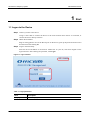
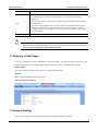
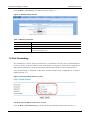
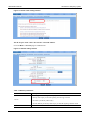
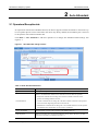
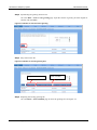
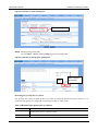
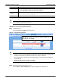
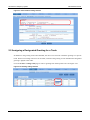
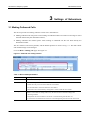
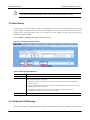
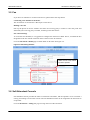
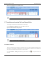
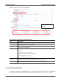
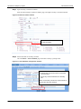
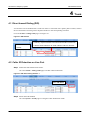
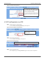
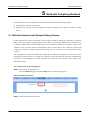
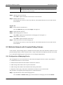
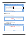
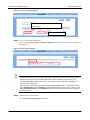
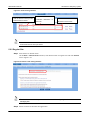
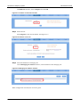
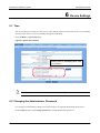
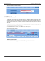
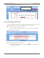
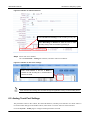
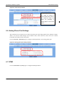
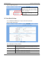
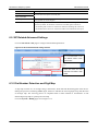
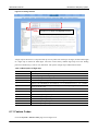
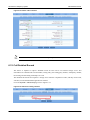
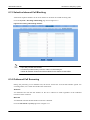
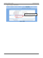
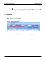
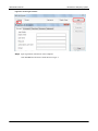
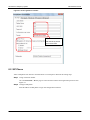
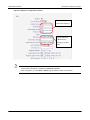
New Rock Technologies, Inc. OM Series IP Telephony System Administrator Manual OM12 OM80 OM200 http://www.newrocktech.com Tel: +86 21-61202700 Fax: +86 21-61202704 Document Version: AA0-E001-N Manual Description This manual is applicable to New Rock’s OM series office IP telephony system (referred to as the “device”) with firmware release version 74. It describes how to use Web utility to manage the device, including parameter configuration and maintenance operation such as firmware upgrade, capturing log files and etc. Notice that some frequent used parameters can be configured on a phone, as described in OM’s User Manual. Contents 1 Start ............................................................................................................................................................. 1-1 1.1 Logon to the Device ........................................................................................................................................... 1-1 1.2 Directory of Web Pages ..................................................................................................................................... 1-2 1.3 Network Settings ................................................................................................................................................ 1-2 1.4 Port Forwarding ................................................................................................................................................. 1-3 2 Auto Attendant ........................................................................................................................................... 2-1 2.1 Operators/Receptionists .................................................................................................................................... 2-1 2.2 Greetings ........................................................................................................................................................... 2-2 2.2.1 Factory Default Greetings ....................................................................................................................... 2-2 2.2.2 Changing the Greetings .......................................................................................................................... 2-2 2.3 Greeting Repeat................................................................................................................................................. 2-6 2.4 Playing Greetings Depending on Business Hours ............................................................................................. 2-6 2.5 Assigning a Designated Greeting for a Trunk .................................................................................................... 2-7 3 Settings of Extensions .............................................................................................................................. 3-1 3.1 Making Outbound Calls ...................................................................................................................................... 3-1 3.2 Hunt Group ........................................................................................................................................................ 3-2 3.3 Outbound Call Barring ....................................................................................................................................... 3-2 3.4 Group Call Pick up ............................................................................................................................................. 3-3 3.5 Fax ..................................................................................................................................................................... 3-4 3.6 Soft Attendant Console ...................................................................................................................................... 3-4 3.7 Transferring an Incoming Call to an External Party............................................................................................ 3-5 3.8 Other Features ................................................................................................................................................... 3-5 3.9 Secretary Assistant ............................................................................................................................................ 3-6 4 Trunk ........................................................................................................................................................... 4-1 4.1 Direct Inward Dialing (DID) ................................................................................................................................ 4-1 4.2 Caller ID Detection on Line Port ........................................................................................................................ 4-1 4.3 SIP Trunk Registration to an ITSP ..................................................................................................................... 4-2 5 Multi-site Telephony Network................................................................................................................... 5-1 5.1 Multi-site Network with Simple Dialing Scheme ................................................................................................. 5-1 5.2 Multi-site Network with Complex Dialing Scheme .............................................................................................. 5-3 5.2.1 Configuration of Managing Device .......................................................................................................... 5-3 5.2.2 Regular Site ............................................................................................................................................ 5-6 6 Device Settings .......................................................................................................................................... 6-1 6.1 Time ................................................................................................................................................................... 6-1 6.2 Changing the Administrator Password ............................................................................................................... 6-1 6.3 SIP Client Account ............................................................................................................................................. 6-2 6.4 Call Recording and Voicemail ............................................................................................................................ 6-3 6.5 Analog Trunk Port Settings ................................................................................................................................ 6-4 6.6 Analog Phone Port Settings ............................................................................................................................... 6-5 6.7 DTMF ................................................................................................................................................................. 6-5 6.8 Voice Media Settings ......................................................................................................................................... 6-6 6.9 SIP Related Advanced Settings ......................................................................................................................... 6-7 6.10 Dial Number Detection and Digit Map .............................................................................................................. 6-7 6.11 Feature Codes ................................................................................................................................................. 6-8 6.12 Call Detailed Record ........................................................................................................................................ 6-9 6.13 Selective Inbound Call Blocking ..................................................................................................................... 6-10 6.14 Outbound Call Screening ............................................................................................................................... 6-10 7 Maintenance ............................................................................................................................................... 7-1 7.1 Firmware Upgrading .......................................................................................................................................... 7-1 7.2 System Reboot .................................................................................................................................................. 7-2 7.3 Export Configuration Files .................................................................................................................................. 7-3 7.4 Import Configuration Files .................................................................................................................................. 7-4 8 Appendix:Registering a SIP Terminal to OM ........................................................................................ 8-1 8.1 Softphone .......................................................................................................................................................... 8-1 8.2 SIP Phone .......................................................................................................................................................... 8-3 Contents of Figure Figure 1-1 Login interface ........................................................................................................................................ 1-1 Figure 1-2 Directory interface .................................................................................................................................. 1-2 Figure 1-3 Network setting interface ........................................................................................................................ 1-3 Figure 1-4 Port forwarding interface of router .......................................................................................................... 1-3 Figure 1-5 Domain name setting interface ............................................................................................................... 1-4 Figure 1-6 Network setting interface ........................................................................................................................ 1-4 Figure 2-1 Auto-Attendant setting interface ............................................................................................................. 2-1 Figure 2-2 DNS service interface ............................................................................................................................. 2-2 Figure 2-3 Interface to enter the text of greeting ...................................................................................................... 2-3 Figure 2-4 Interface to save the greeting files .......................................................................................................... 2-3 Figure 2-5 Interface to select greeting files .............................................................................................................. 2-4 Figure 2-6 Interface to managing the greeting files .................................................................................................. 2-4 Figure 2-7 Greeting setting interface........................................................................................................................ 2-5 Figure 2-8 Auto-attendant interface ......................................................................................................................... 2-6 Figure 2-9 Time schedule setting interface .............................................................................................................. 2-7 Figure 2-10 Greeting setting interface...................................................................................................................... 2-7 Figure 3-1 Outbound calls setting interface ............................................................................................................. 3-1 Figure 3-2 Hunt group setting interface.................................................................................................................... 3-2 Figure 3-3 Outbound call barring setting interface ................................................................................................... 3-3 Figure 3-4 Group setting interface ........................................................................................................................... 3-3 Figure 3-5 Group assigning interface ....................................................................................................................... 3-3 Figure 3-6 FAX setting interface .............................................................................................................................. 3-4 Figure 3-7 Soft attendant console setting interface .................................................................................................. 3-5 Figure 3-8 Outbound transfer setting interface ........................................................................................................ 3-5 Figure 3-9 Extension’s feature setting interface ....................................................................................................... 3-6 Figure 3-10 Extesion feature interface ..................................................................................................................... 3-7 Figure 3-11 Auto attendant configuration interface .................................................................................................. 3-7 Figure 4-1 DID interface........................................................................................................................................... 4-1 Figure 4-2 CID detect setting interface 1 ................................................................................................................. 4-1 Figure 4-3 CID detect setting interface 2 ................................................................................................................. 4-2 Figure 4-4 IP trunk registration setting interface ...................................................................................................... 4-2 Figure 4-5 IP trunk setting interface ......................................................................................................................... 4-2 Figure 4-6 Registration status interface ................................................................................................................... 4-3 Figure 5-1 Multi-site scenarios ................................................................................................................................. 5-1 Figure 5-2 Auto discovery of devices ....................................................................................................................... 5-2 Figure 5-3 Device list setting interface ..................................................................................................................... 5-2 Figure 5-4 Domain name interface .......................................................................................................................... 5-4 Figure 5-5 Multi-site scenarios setting interface ....................................................................................................... 5-4 Figure 5-6 Role selecting interface .......................................................................................................................... 5-4 Figure 5-7 Device list setting interface ..................................................................................................................... 5-5 Figure 5-8 Prefix setting interface ............................................................................................................................ 5-5 Figure 5-9 Trunk sharing interface ........................................................................................................................... 5-6 Figure 5-10 Domain name setting interface ............................................................................................................. 5-6 Figure 5-11 Interface of multi-site scenarios ............................................................................................................ 5-7 Figure 5-12 Interface of site role .............................................................................................................................. 5-7 Figure 5-13 Managing site address interface ........................................................................................................... 5-7 Figure 5-14 Multi-site networking status interface .................................................................................................... 5-8 Figure 6-1 System time interface ............................................................................................................................. 6-1 Figure 6-2 Interface of changing password .............................................................................................................. 6-2 Figure 6-3 IP extension interface ............................................................................................................................. 6-2 Figure 6-4 Adding IP extension in bulk interface ...................................................................................................... 6-3 Figure 6-5 Recording/Voicemail interface ................................................................................................................ 6-3 Figure 6-6 Interface of extension features ............................................................................................................... 6-4 Figure 6-7 Interface of mail server settings .............................................................................................................. 6-4 Figure 6-8 Trunk setting interface ............................................................................................................................ 6-5 Figure 6-9 Analog phone port setting interface ........................................................................................................ 6-5 Figure 6-10 DTMF setting interface ......................................................................................................................... 6-6 Figure 6-11 Media setting interface ......................................................................................................................... 6-6 Figure 6-12 SIP related advanced setting interface ................................................................................................. 6-7 Figure 6-13 Dialing interface .................................................................................................................................... 6-8 Figure 6-14 Feature codes interface ........................................................................................................................ 6-9 Figure 6-15 CDR server setting interface................................................................................................................. 6-9 Figure 6-16 Incoming call blocking interface .......................................................................................................... 6-10 Figure 6-17 Interface of call screening ................................................................................................................... 6-11 Figure 7-1 Firmware upgrading interface ................................................................................................................. 7-1 Figure 7-2 Interface of upgrade firmware ................................................................................................................. 7-2 Figure 7-3 Firmware upgrading interface ................................................................................................................. 7-2 Figure 7-4 System restarting interface ..................................................................................................................... 7-3 Figure 7-5 Exporting configuration files interface ..................................................................................................... 7-3 Figure 7-6 Importing configuration files interface ..................................................................................................... 7-4 Figure 8-1 Account creating interface ...................................................................................................................... 8-1 Figure 8-2 X-Lite login interface ............................................................................................................................... 8-2 Figure 8-3 X-Lite registration interface ..................................................................................................................... 8-3 Figure 8-4 SIP phone configuration interface ........................................................................................................... 8-4 Contents of Table Table 2-3 Recording the greeting file on a phone .................................................................................................... 2-4 Table 3-1 Dial scheme parameters .......................................................................................................................... 3-1 Table 3-2 Hunt group parameters ............................................................................................................................ 3-2 Table 3-3 Extension feature related parameters ...................................................................................................... 3-6 Table 5-1 Multi-site network parameters .................................................................................................................. 5-2 Table 6-1 Description of media parameters ............................................................................................................. 6-6 Table 6-2 Description of Digit map ........................................................................................................................... 6-8 OM Series IP Telephony System Administrator Manual 1 Start 1.1 Logon to the Device Step1 Connect your PC to the device Using a CAT5 cable to connect the device to the local network where the PC is connected, or connect the device directly to the PC. Step2 Obtain the IP address Plug an analog phone to one of the Phone ports on the device; pick up the phone and listen to the announcement after dialing ##. Step3 Login to the Web utility Enter the device IP address in the browser address bar on your PC, and select English on the logon interface. After entering the password, click Login. Figure 1-1 Login interface Table 1-1 Login parameters Item Description Language Select a language. www.newrocktech.com 1-1 Administrator Manual Item OM Series IP Telephony System Description The Web utility provides two authority levels, administrator and operator. An administrator is allowed to make changes to any configuration and login passwords. An operator is allowed to navigate configuration pages and make limited changes to configurations. The device allows multiple users to login, in which case the administrator has the authority of changing the configuration while the operator is limited to read the configuration only. In any situation, there is only one user allowed to make changes to configurations. Role Password admin by default. Before logon to the Web utility, make sure the PC and the device are on the same subnet. Please change the default password after your first time logon to the Web utility and keep it secure. See Chapter 6.2 Changing the administrator password. 1.2 Directory of Web Pages If you are unfamiliar with the organization of the Web utility, the directory links on the top of the interface can help you to navigate the Web pages based on the tasks you would like to perform. Feature Index The index of features and functions directs you to the intended pages. Directory The sitemap of the Web utility is presented. Figure 1-2 Directory interface 1.3 Network Settings The networks settings may need to be changed based on the installation conditions. 1-2 www.newrocktech.com OM Series IP Telephony System Administrator Manual Go to the Basic > Network page for network settings. See Fig. 1-3. Figure 1-3 Network setting interface Table 1-2 Network parameters Item Description Static To assign a static IP address. This is the default setting. DHCP Use the dynamic host configuration protocol (DHCP) to allocate IP addresses. PPPoE Select PPPoE when ADSL modem is connected to the device, and enter username and password obtained from ISP. 1.4 Port Forwarding Port forwarding is used to permit external hosts to communicate with the device installed behind a router in a private local area network. Such communication is required in remote device management, SIP terminal registration to the device and the SIP trunk between the device and an external device. The port forwarding is configured on the router, and the example of the configuration on a router is illustrated in Fig. 1-4. Figure 1-4 Port forwarding interface of router The WAN port IP address of the router is static Go to the Basic > Domain name page and enter WAN port IP address of the router. See Fig. 1-5. New Rock Technologies, Inc. 1-3 Administrator Manual OM Series IP Telephony System Figure 1-5 Domain name setting interface The WAN port of the router does not have a fixed IP address Go to the Basic > Network page to enable STUN. Figure 1-6 Network setting interface Table 1-3 Network parameters Item Description Select a trigger for launching STUN inquiry: Startup: make inquiry for the SIP signaling when the App activated Periodical: periodically make inquiry Periodic & RTP: periodically make inquiry for both SIP signaling and RTP stream STUN STUN Server 1-4 Enter the IP address of STUN server, such as 20.125.2.29. www.newrocktech.com OM Series IP Telephony System Administrator Manual 2 Auto Attendant 2.1 Operators/Receptionists In conjunction with the auto attendant function, the device supports manual call transfer to extensions. Up to five operator phones can be connected to the device. By factory default, the first Phone port is reserved to the operator with extension number 200. Click Basic > Auto Attendant to add more operators or to change auto attendant related settings. See Figure 2-1. Figure 2-1 Auto-Attendant setting interface Table 2-1 Auto-attendant Parameters Item Description Operator Enter up to five operators’ extension numbers, separated with “,”. Select a call distribution scheme below when there are more than one operator: Call Distribution Sequential: terminate the incoming call to the first available extension on the operator list starting from the first one; Circular: terminate the incoming call to the first available extension on the operator list in fixed order beginning from the last one left off; Simultaneous: terminate the incoming call to all available extensions on the operator list simultaneously and the first one to pick up is connected. Call to an Operator This dial prefix is used to call an operator. The default prefix is 0. Ring the phone When an incoming call is not answered after the set ring times, the device provides busy tone to the caller. The default ring time is 5. New Rock Technologies, Inc. 2-1 Administrator Manual OM Series IP Telephony System 2.2 Greetings The device provides a greeting voice message to the caller when a call comes in, and the content of the greeting may vary depending on the time. 2.2.1 Factory Default Greetings There are two default greetings, one for business hours and one for off-business hours, as shown in Table 2-2. Table 2-2 Default greeting files Type File name Content business hours welcome Thank you for calling. If you know your party’s extension, please dial it now. Or, to transfer to an operator, press zero. off-business hours Off-hour Thank you for calling. Our office is closed. If you know the extension, please dial it now. 2.2.2 Changing the Greetings Three ways are provided to change the greetings: Synthesizing the greetings based on the text content. Recording the greetings via a phone connecting to the device. Uploading the prepared greeting files to the device. Synthesizing greetings This is a simple way to customize the greetings in Chinese or English with high voice quality. The synthesizing service is provided by the speech synthesis engine publically accessible on the Internet, offered by New Rock Technologies, Inc., and to perform the synthesis the device is required to connect to the Internet. Step1 Enable the DNS service Go to the Basic > Network page to enable/configure DNS server. See Figure 2-2. Figure 2-2 DNS service interface 2-2 www.newrocktech.com OM Series IP Telephony System Administrator Manual Step2 Synthesizing the greeting file from text Go to the Basic > Text to voice greeting page. Input the content of greeting in either English or Chinese and click Start. Figure 2-3 Interface to enter the text of greeting Step3 Play and save the file Figure 2-4 Interface to save the greeting files Play the voice file. Save voice files. Step4 Replacing the existing greeting file Go to the Basic > Auto-attendant page to select the greeting file. See Figure 2-5. New Rock Technologies, Inc. 2-3 Administrator Manual OM Series IP Telephony System Figure 2-5 Interface to select greeting files Select a greeting file. Step5 Managing the greeting files Go to the Basic > Text to voice greeting page for file management. Figure 2-6 Interface to managing the greeting files Make changes to Play the greetings. Recording the greeting file via a phone The greeting file can be recorded directly on a phone by using the operations listed in Table 2-3. To ensure the high quality, it is suggested to make the recording in a quiet room. Table 2-3 Recording the greeting file on a phone 2-4 Item Operation Recording Pick up any phone connecting to the device and press *81 to start the recording after the prompt, and hang up the phone to finish the recording. Listen Press *8200 to listen to the voice recording www.newrocktech.com OM Series IP Telephony System Item Administrator Manual Operation Save Play the latest greeting file Recovery Press *8301 and hang up the phone to replace the welcome file, or Press *8302 and hang up the phone to replace the off-hour file. Press *8201 to listen to welcome greetings; Press *8202 to listen to off-hour greetings. Press *8300 to recover replaced voice greeting file. Never restart your device during recording. Uploading a prepared greeting file to the device Step1 Uploading the file Go to the System > Greeting page. See Figure 2-7. Figure 2-7 Greeting setting interface Click Browse to select a greeting file in G.729 format, such as user1.dat, and click Upload. For G.711 voice file, the name should be in the format of userxxx.pcm, and for G.729 voice file should be in the format of userxxx.dat, where the xxx is a string of characters. An audio tool such as ‘Cool Edit’ can be used to transform the voice file into other formats, like G.711 or G.729. Restart the device after the uploading to take effect. Step2 Replacing the default file with the new one Go to the Basic > Auto-attendant page to select the greeting file. See Figure 2-5. New Rock Technologies, Inc. 2-5 Administrator Manual OM Series IP Telephony System 2.3 Greeting Repeat The device plays a greeting to callers of incoming call and followed by a voice menu for callers to select the terminating party. While it waits for callers to enter the selection or enter an extension number it replays the greeting several times. By default, the device replays the greeting three times before it directs the calls to an operator for assistance. The greeting repeat can be set as shown in Fig. 2-8. Go to the Basic > Auto-attendant page to set repeating times. See Figure 2-8. Figure 2-8 Auto-attendant interface 2.4 Playing Greetings Depending on Business Hours The business and off-business hours and their related greetings can be set. Go to the Basic > Auto-attendant page to define the work schedule. 2-6 www.newrocktech.com OM Series IP Telephony System Administrator Manual Figure 2-9 Time schedule setting interface 2.5 Assigning a Designated Greeting for a Trunk In addition to the greeting of the auto-attendant, the device can associate a dedicate greeting to a specific trunk. When an incoming call arrives at the trunk, instead of the greeting of auto attendant the designated greeting is played to the caller. Go to the Trunk > Analog trunk page to select a greeting from the drop-down list. See Figure 2-10. Figure 2-10 Greeting setting interface New Rock Technologies, Inc. 2-7 OM Series IP Telephony System Administrator Manual 3 Settings of Extensions 3.1 Making Outbound Calls The device provides two dialing schemes to meet users’ dial behavior: Making outbound call with prefix: when making an outbound call the user dials an extra digit to select the trunk followed by the destination number; Making outbound call without prefix: when making an outbound call the user dials directly the destination number. The first scheme is the factory default, and the default prefixes are shown in Fig. 3-1. The dial scheme and related settings can be changed. Go to the Basic > Dialing rule page. See Figure 3-1. Figure 3-1 Outbound calls setting interface Table 3-1 Dial scheme parameters Item Description Prefix Choose a Prefix for a specific route; Route The device can provides different routes of outbound call for user to select Hunting www.newrocktech.com FXO: the Line port is selected to make the call to PSTN IP: the SIP trunk is selected to make the call to PSTN Route table: the route defined by routing table is used to make the call to PSTN If there is more than one analog trunk (Line), the line selection is made according to the following schemes. Sequential: the first available line on the list is selected starting from the first one Circular: the first available line on the list is selected beginning from the one left off last time 3-1 Administrator Manual OM Series IP Telephony System When direct outward dialing is enabled, press * before dialing another extension number. 3.2 Hunt Group A hunt group is a set of extensions which are organized to process specific calls. When the dial prefix of the hunt group is dialed by the user the device terminates the call to an available extension in the hunt group. Users can dial the prefix, such as 1 for sales and 2 for support, in both voice menu of auto attendant and direct dialing. Go to the Basic > Dialing rule page for hunt group setting. Figure 3-2 Hunt group setting interface Table 3-2 Hunt group parameters Item Description Prefix Choose the prefix of a hunt group, like 3. Hunting Select a hunting scheme of the group: Extension Sequential: terminate the incoming call to the first available extension in the group starting from the first one; Circular: terminate the incoming call to the first available extension in the group in fixed order beginning from the last one left off; Simultaneous: terminate the incoming call to all available extensions in the group simultaneously and the first one to pick up is connected. Enter the extensions in the group, separated by a comma. 3.3 Outbound Call Barring Each extension has an assigned privilege of making outbound call. When a user makes a call beyond its 3-2 www.newrocktech.com OM Series IP Telephony System Administrator Manual restriction, the device rejects the call with a voice announcement. The definitions of restriction level are listed below. Go to the Extension > Analog ext. page to define extension’s restriction level. See Figure 3-3. Figure 3-3 Outbound call barring setting interface 3.4 Group Call Pick up The users are allowed to pick up a ringing phone of others in the same group by dialing *56. The call pick up group can be set as follows. Step1 Create the name of a group Go to the Extension > Group page to name the group. Figure 3-4 Group setting interface Step2 Assign a group to extensions Go to the Extension > Analog ext. page to assign a group to extensions. Figure 3-5 Group assigning interface These extensions are in the group of Software. www.newrocktech.com 3-3 Administrator Manual OM Series IP Telephony System 3.5 Fax If you have fax machines to connect to the device, please follow the steps below. Connecting a fax machine to the device The fax machine is connected to a Phone port on the device. Making a fax call Pick up the phone on the fax machine and enter the receiving party’s number or enter the prefix and followed by the receiving party’s number, according to the dial scheme. Fax related settings To avoid the auto attendant, it is suggested to configure the extension as DID. That is, to bundle the line designated to the fax with the extension which connects to the fax machine. Go to the Advanced > Media page to enable FoIP via IP trunk. See Figure 3-6. Figure 3-6 FAX setting interface Select the fax mode offered by service provider. 3.6 Soft Attendant Console Soft attendant console provides the status of extensions and trunks, and the operators use it to transfer a call by just making a click on the console. The soft attendant console can be assigned to the extensions as an Operator. Go to the Extension > Analog ext. page to assign the role of the extensions. 3-4 www.newrocktech.com OM Series IP Telephony System Administrator Manual Figure 3-7 Soft attendant console setting interface The soft attendant console is a Windows-based software provided by New Rock. 3.7 Transferring an Incoming Call to an External Party An incoming call is allowed to be transferred to an external party. Go to the Extension > Analog ext. page to select OT. See Figure 3-8. Figure 3-8 Outbound transfer setting interface During an outbound transfer, two lines are used. 3.8 Other Features The device provides dozens of features for extension users, such as call forwarding, speed dialing, color ring back tone, call forking, recording and etc. Some of the features are enabled as factory default and others need to be enabled by the administrator as shown in below. Go to the Extension > Analog ext. /IP ext. page and click the icon to set up other features of extension. www.newrocktech.com 3-5 Administrator Manual OM Series IP Telephony System Figure 3-9 Extension’s feature setting interface Enable features of each extension. Table 3-3 Extension feature related parameters Item Description PIN number Using *33 & *99 to allow users to access the device with an external phone. Calling with PIN Select it to enable the PIN on the extension. When the user needs to make outbound calls, the PIN should be entered before the calling number. Mobile Instead of PIN number a mobile phone number of the user can be used for auto authentication of *33 and *99 for external access. Call forwarding Select one of the settings of call forwarding feature: Disable Forwarding all calls to another phone Forwarding unanswered calls to another phone Forwarding all calls to voicemail Forwarding unanswered calls to voicemail Forwarding number Enter the destination number of forwarding calls. Depending on the outbound dial scheme a prefix may be required, separated from the phone number with comma. Forking number The forking function allows the device to terminate a call simultaneously to the extension and another terminal. Enter the phone number of the terminal to enable the feature. 3.9 Secretary Assistant A secretary’s extension can be bundled with his or her manager’s extension so that a call to the manager will be redirected to the secretary and further transferred to the manager’s extension by the secretary. 3-6 www.newrocktech.com OM Series IP Telephony System Administrator Manual Step1 Input secretary’s extension number Enter into the manager’s extension feature page, and input secretary’s extension number. Figure 3-10 Extesion feature interface Enter the secretary’s extension to enable the feature. Step2 Select the mode of secretary assistant Go to the Basic > Auto-attendant page and select secretary’s pickup mode. Figure 3-11 Auto attendant configuration interface External call: only external calls are transfered to the secretary. All call: any call is transfered to the secretary first. Note: the secretary should use explicit transfer to transfer the call to the manager. www.newrocktech.com 3-7 OM Series IP Telephony System Administrator Manual 4 Trunk 4.1 Direct Inward Dialing (DID) An extension can be bundled with a trunk line which is associated with a public phone number, and the device forwards the incoming call to the phone number to the corresponding extension. Go to the Trunk > Analog trunk page. See Figure 4-1. Figure 4-1 DID interface Enter the extension DID only: only the extension can make outbound calls over the trunk. Allowed: other extensions can make outbound calls over the trunk. number. 4.2 Caller ID Detection on Line Port Step1 Enable the caller ID detection feature. Go to the Trunk > Analog trunk page to enable caller ID detection. Figure 4-2 CID detect setting interface 1 Select CID detect. Step2 Select caller ID standard. Go to the System > Trunk page to configure Caller ID detection mode. www.newrocktech.com 4-1 Administrator Manual OM Series IP Telephony System Figure 4-3 CID detect setting interface 2 The central office sends caller ID either before or after ringing. The caller ID detection should be configured accordingly. Note: when the device fails to detect the caller ID, different mode listed here should be tried out. 4.3 SIP Trunk Registration to an ITSP Step1 Configure ISTP server related settings Go to the Trunk > IP trunk registration page. See Figure 4-4. Figure 4-4 IP trunk registration setting interface Input information required by the service provider. Step2 Enter username and password Go to the Trunk > IP trunk page. See Figure 4-5. Figure 4-5 IP trunk setting interface Enter phone number and password assigned by the service, and click Add. Step3 Verify the registration status After configuration, go to the Logs > Resource page to check the status of registration. 4-2 www.newrocktech.com OM Series IP Telephony System Administrator Manual Figure 4-6 Registration status interface Registration of IP trunk succeeds. www.newrocktech.com 4-3 OM Series IP Telephony System Administrator Manual 5 Multi-site Telephony Network Devices installed in one or multiple sites can be interconnected for the following purposes: Expanding the capacity of the facility; Making direct and free inter-site calling and making outbound call to PSTN via trunks on other devices. 5.1 Multi-site Network with Simple Dialing Scheme In this simple form of multi-site network, inter-site calls are made by dialing the called party’s extension without extra prefix digits. The dialing plan of this scheme is simple and straightforward, and therefore, it is suitable to applications in which multiple devices are stacked to expand the port capacity , and it is also suitable to form a private network of headquarter and its branch offices. The multi-site network with simple form requires a carefully designed numbering plan for each device to avoid potential number conflicts. The configuration of multi-site network with simple form includes the configurations of the device on the managing site and the devices on regular sites. The device list of the multi-site network is maintained by the device on the managing site, which distributes the device list to the devices on the regular sites, illustrated as below. The configuration on the managing site Step1 Select multi-site network form Go to the Multi-site page and select Simple as the scenario. See Figure 5-1. Figure 5-1 Multi-site scenarios Step2 Enable auto discovery of devices www.newrocktech.com 5-1 Administrator Manual OM Series IP Telephony System Figure 5-2 Auto discovery of devices Step3 Add the managing site to the device list Click Add to enter information of the managing site. Figure 5-3 Device list setting interface Click Add to input relevant information. Table 5-1 Multi-site network parameters Item Description IP address IP address and port number of a device. Note: the address of the managing site must be set on the top of the list. Prefix The expression of the extension numbers of the device. For example, 2/3 expresses 3-digit number started with 2. Note: The numbering plans of devices involved in the network must be carefully examined to avoid potential number conflicts. A number conflict is a situation in which a prefix of an extension number on one device is identical to the prefix of an extension number on another device. E.g.: suppose the expressions of device A and B are 2/3 and 21/3, respectively. When the user of device A dials 210, an extension in local, the call could be routed to device B. Whether to select a trunk for outbound calling on other devices Allow the trunks on the device to be used for outbound calling originated from other devices. Area code Fill in the area codes of the device. A call to the region covered by the area codes could be routed via the trunk of the devoce. 5-2 www.newrocktech.com OM Series IP Telephony System Administrator Manual Item Description Pilot number Enter the pilot number of this device. When the IP connection is disconnected, the inter-site calling will be routed via PSTN. Step4 Add other devices to the list Click Add to input information of other devices in the network. Step5 Broadcast the device list The managing site, which is on the top of the list, will send the latest device list to other devices in the network. Regular Site Step1 Select multi-site network form Go to the Multi-site page and select Simple. See Figure 5-1. Step2 Enable the auto discovery Step3 Add managing device to the list Click Add to input relevant information of managing site. See Figure 5-3. Step4 Add this device to the list Click Add to input information of the device. Step5 Get the latest device list from managing site The managing site, which is on the top of the list, will send the latest device list to other devices in the network. 5.2 Multi-site Network with Complex Dialing Scheme In this scheme, special dialing digits are added at the front and the end of the destination number to avoid potential dialing number conflict. With this form, a large scaled multi-site telephony network can be built up, in which the numbering plan of each device can be managed independently. 5.2.1 Configuration of Managing Device The managing device is one of the devices in the multi-site telephone network, which is responsible to Authenticate the devices in the network Maintain and broadcast the latest address information of devices Make change and broadcast the site prefix information Make change and broadcast the outbound trunk sharing information Response to the inquiry of the above information from other devices in the network The procedure of configuring the managing device is illustrated below. Step1 Input the domain name of the managing device Go to the Basic > Domain name page. Enter IP address of managing site and click Submit. www.newrocktech.com 5-3 Administrator Manual OM Series IP Telephony System Figure 5-4 Domain name interface Enter IP address/domain name of the device. A static IP address is required for managing site. Step2 Select multi-site form On Multi-site interface, select Complex for Multi-site scenarios, and click OK. See Figure 5-5. Figure 5-5 Multi-site scenarios setting interface Step3 Select the role of a managing site Select Managing as the role and click Submit. Figure 5-6 Role selecting interface Step4 Create the device list Enter into the Add and update sites page. See Figure 5-7. 5-4 www.newrocktech.com OM Series IP Telephony System Administrator Manual Figure 5-7 Device list setting interface Input information of site identities relevant to domain name. Site ID must be unique. Step5 Create or update the dialing prefix Enter into the Change prefix of multi-site calling interface to create or change the dialing prefix. See Figure 5-8. Figure 5-8 Prefix setting interface The domain name and the port number will be used in configuring the device list on managing site. Dialing prefix of inter-site calling is dialed before the extension number of the remote site. For example, #1-11-200#, in which 1 is the prefix, 11 is the site id of the called party, and 200 is the extension of the called party. Dialing prefix of outbound calling is dialed ahead of the destination number. For example by dialing #1-11-8005551212# the call to 8005551212 will be routed to PSTN through a trunk on site 11, and by dialing #2-8005551212# the call to 8005551212 will be routed to PSTN through a trunk selected by the managing site. Step6 Configuration of trunk sharing Go to Trunk sharing management interface. www.newrocktech.com 5-5 Administrator Manual OM Series IP Telephony System Figure 5-9 Trunk sharing interface Add the devices which provide shared trunks to PSTN. Enter the area codes of the reachable destination the trunk. of List the sites which are allowed to use the trunk. Unless the site ID is dialed for the outbound call to PSTN, the device will search the allowed outbound trunk from the top of the list. 5.2.2 Regular Site Step1 Enter the device domain name On the Basic > Domain name interface, enter domain name of regular sites and click Submit seen in Figure 5-10. Figure 5-10 Domain name setting interface The domain name and the port number will be used in configuring the device list on managing site. Step2 Select scenarios of the multi-site application 5-6 www.newrocktech.com OM Series IP Telephony System Administrator Manual On Multi-site interface, select Complex and click OK. Figure 5-11 Interface of multi-site scenarios Step3 Select the role Select Regular as the role and submit. See Figure 5-12. Figure 5-12 Interface of site role Step4 Enter the IP address of managing site On the Managing site address interface, enter IP address of the managing site. Figure 5-13 Managing site address interface When configuration succeeds, the icon turns green. www.newrocktech.com 5-7 Administrator Manual OM Series IP Telephony System Figure 5-14 Multi-site networking status interface 5-8 www.newrocktech.com OM Series IP Telephony System Administrator Manual 6 Device Settings 6.1 Time The device obtains its time from a time server in the network, and in case the time service is not available, the timer of the device can be set manually through the Web utility. Go to the Basic > System time page. Figure 6-1 System time interface Primary server & Secondary server fields must be filled in. If the system fails to synchronize to the time server, click Change to manually set the time. 6.2 Changing the Administrator Password It is strongly recommended to change your password after you login the Web utility the first time. On the Tools interface, click Change password to modify administrator password. www.newrocktech.com 6-1 Administrator Manual OM Series IP Telephony System Figure 6-2 Interface of changing password 6.3 SIP Client Account A SIP based voice terminal can be connected to the device, including softphone and SIP phone. After registering to the device, the SIP terminals can communicate to other terminals connected to the device, such as terminals on FXS ports, SIP phones, and remote terminals through analog trunks, tie trunks and SIP trunks. A SIP account needs to be set up on the device for each SIP terminals. The device will reject any visit from a SIP terminal which fails in authentication. On the Extension > IP ext. interface, click Add to register. See Figure 6-3. Figure 6-3 IP extension interface Adding IP extension in bulk Go to the Extension > IP ext. page, and click Batch add to input relevant information. 6-2 www.newrocktech.com OM Series IP Telephony System Administrator Manual Figure 6-4 Adding IP extension in bulk interface Click Batch add to fulfill relevant information. 6.4 Call Recording and Voicemail A file server is required in order to use call recording and voicemail functions. In addition, a mail server is required if the messages of the voicemail are forwarded to the receipts through email. Step1 Configure the file server and mail server addresses On the System > Recording/Voicemail interface, enter relevant information of recording/mail server. Figure 6-5 Recording/Voicemail interface Step2 Enable the recording function of an extension On the Extension > Analog/IP ext. interface, click the icon of extension and enable recording. www.newrocktech.com to enter into configuration page 6-3 Administrator Manual OM Series IP Telephony System Figure 6-6 Interface of extension features Select Permanent recording to make recording to every call. Select Recording on demand to allow the user to make recording during a call conversation by pressing *#. Step3 Fill in mail server address Go to the Extension > Analog ext. interface, and fill in mail server address. Figure 6-7 Interface of mail server settings Enter e-mail address in the box of Email to forward the call recording file or voicemail file to the user via email. Users can listen and manage the voice files through the application running on the recording server. 6.5 Analog Trunk Port Settings The parameters relate to the volume, the caller ID detection, and busy tone detection of a trunk. There is no need to make changes to the default values, unless there is an issue with one of the functions. Go to the System > Trunk page to configure related parameters of trunk. 6-4 www.newrocktech.com OM Series IP Telephony System Administrator Manual Figure 6-8 Trunk setting interface During the process of dialing out, DTMF out pulsing is started 600ms after hook-off. The shorter the delay, the higher the probability of missing digits on the CO side will be. 6.6 Analog Phone Port Settings The parameters are provided to have better interconnection with analog phones from different vendors. There is no need to make changes to the default values, unless there are issues with voice volume, hook-flash and caller ID sent to the phone. Go to the System > Extension page to configure related parameters of an analog phone port. Figure 6-9 Analog phone port setting interface 6.7 DTMF Go to the Advanced > System page to configure DTMF parameters. www.newrocktech.com 6-5 Administrator Manual OM Series IP Telephony System Figure 6-10 DTMF setting interface RFC2833, inband, and SIP INFO are supported for transmitting DTMF signals. When RFC2833 is chosen, the payload type should be configured, which is 101 by default. DTMF detection threshold/adjust are used for DTMF reception. 6.8 Voice Media Settings Go to the Advanced > Media page to configure media related parameters. Figure 6-11 Media setting interface Table 6-1 Description of media parameters 6-6 Item Description Codec Valid values are G729A/20, PCMU/20 and PCMA/20, and multiple codecs can be entered, separating with a comma. Min. RTP port The lower bound of RTP transmission and receiving port. The valid range is 10010-10500. Max. RTP port The upper bound of RTP transmission and receiving port. This value must be greater than or equal to “2× number of lines+min. RPT port”. TOS/DSCP This parameter specifies the priorities of media stream. www.newrocktech.com OM Series IP Telephony System Administrator Manual Item Description Min. jitter buffer Used to reduce the impact of network jitter. Max. jitter buffer RTP drop SID If it is selected the received RTP SID voice packets will be discarded. By default, SID voice packets will not be dropped. RTP destination address This parameter specifies how to obtain the IP address of the receiving side for RTP packets. By default, the IP address is obtained “From SDP global connection”. From SDP global connection: obtain the IP address from SDP global connection; From SDP media connection: obtain the IP address from SDP media description. 6.9 SIP Related Advanced Settings Go to the Advanced > SIP page to configure advanced SIP parameters. Figure 6-12 SIP related advanced setting interface It is recommended to use the default values of SIP parameters. These two items are used when the soft switch is IMS based. 6.10 Dial Number Detection and Digit Map A digit map consists of a set of digit strings, called rules, which describe the dialing plan of the device. During the process of collecting DTMF digits, the device matches the receiving digit string with the rules in the digit map. The receiving process is completed when a match situation is encountered. A well defined digit map helps to speed up the call setup. Go to the System > Dialing page seen in Figure 6-13. www.newrocktech.com 6-7 Administrator Manual OM Series IP Telephony System Figure 6-13 Dialing interface Click the icon to display the Digit map interface. A digit map in the device is composed with up to sixty rules each with up to 32 digits, and the total length of a digit map is limited to 2280 digits. The rules in the factory default digit map covers the dialing patterns of feature keys, such as *30, and others. The syntax of digit map is illustrated as below. Table 6-2 Description of Digit map Character Description 0-9, *, # Match to specific a DTMF signal. x Match to any 1-digit DTMF signal. E.g.: x can be matched to 1 or 2. . Match to any string of DTMF signals. T End of collecting DTMF digits after timeout of waiting for next digit [] Match to a set of DTMF digits. For example,[1-3,5,7-9] means the set of 1, 2, 3, 5, 7, 8 and 9. x.T Match to a string a DTMF string with any length, and the ending is triggered by the timeout of waiting for the next digit x.# Match to a DTMF string with any length ended with # [2-8]xxxxxxx Match to an 8-digit string starting with of any number between 2 and 8 02xxxxxxxxx Match to an 11-digit string starting with 02 013xxxxxxxxx Match to a 12-digit string starting with 013 13xxxxxxxxx Match to an 11-digit string starting with 13 11x Match to a 3-digit string starting with 11 9xxxx Match to a 5-digit string starting with 9 6.11 Feature Codes Go to the System > Feature codes page seen in Figure 6-14. 6-8 www.newrocktech.com OM Series IP Telephony System Administrator Manual Figure 6-14 Feature codes interface Number conflicts must be avoided while making changes to feature codes. 6.12 Call Detailed Record The device is capable to output a detailed record for each call to an external storage server. The information of a detailed call record includes, among many, the calling party number, called party number, the starting and the ending timestamps of a call. The detailed call records are output to a storage server after the completion of calls, and they can be read, searched, saved and deleted through off-line software. Go to the System > Call record page seen in Figure 6-15. Figure 6-15 CDR server setting interface www.newrocktech.com 6-9 Administrator Manual OM Series IP Telephony System 6.13 Selective Inbound Call Blocking A black list of phone numbers can be set on the device to block un-wanted incoming calls. Go to the System > Incoming call blocking page seen in Figure 6-16. Figure 6-16 Incoming call blocking interface Up to thirty numbers can be listed. The device provides the busy tone if the caller is on the blocking list. Caller ID detection feature should be enabled for this feature to take effect. 6.14 Outbound Call Screening During the processing of an outbound call, the device screens the received dial number against two screening tables, one is white list and the other is black list. White list An outbound call with the dial number on the list is allowed to make regardless of the outbound restriction of the extension. Black list An outbound call with the dial number on the list is blocked. Go to the Advanced > System page seen in Figure 6-17. 6-10 www.newrocktech.com OM Series IP Telephony System Administrator Manual Figure 6-17 Interface of call screening Enter phone numbers separated by |. www.newrocktech.com 6-11 OM Series IP Telephony System Administrator Manual 7 Maintenance 7.1 Firmware Upgrading Step1 Select the Tools > Upgrade page, seen in Figure 7-1. Step2 Click Browse to select the upgrade package. Step3 Click Upload to upload the package to the system. Please contact the supplier to obtain the latest firmware release. Figure 7-1 Firmware upgrading interface Step4 After uploading, click Next to upgrade the system. www.newrocktech.com 7-1 Administrator Manual OM Series IP Telephony System Figure 7-2 Interface of upgrade firmware Step5 When the prompt Upgrade is successful, the system will reboot is shown up, click OK to finish the process of upgrade. Figure 7-3 Firmware upgrading interface 7.2 System Reboot Step1 Go to the Tools > Restart page, seen in Figure 7-4. Step2 Click OK to restart the system. It takes around two minutes to restart the system. 7-2 www.newrocktech.com OM Series IP Telephony System Administrator Manual Figure 7-4 System restarting interface 7.3 Export Configuration Files Step1 Go to the Tools > Export data page seen in Figure 7-5. Step2 Click Download to download and save files to the destination you select. Figure 7-5 Exporting configuration files interface By default, downloaded file will be named after t1.tar.gz, then t2.tar.gz and so on. Recounting begins after restart. www.newrocktech.com 7-3 Administrator Manual OM Series IP Telephony System 7.4 Import Configuration Files Step1 Go to the Tools > Import data page seen in Figure 7-6. Step2 Click Browse to select the packet, like t2.tar.gz. Step3 Click Upload to import data, referring 7.1 Firmware Upgrading. Figure 7-6 Importing configuration files interface 7-4 www.newrocktech.com OM Series IP Telephony System Administrator Manual 8 Appendix:Registering a SIP Terminal to OM 8.1 Softphone CounterPath’s SIP-based softphone X-Lite 3.0 is used to illustrate the configuration steps. Step1 Create an account for the softphone Go to the Extension > IP ext. page and enter the extension number and registration password. Figure 8-1 Account creating interface Step2 Logon to the Web configuration page of X-Lite Enter into the SIP configuration page. Click the button Add… popping up an interface of Properties of Account. www.newrocktech.com 8-1 Administrator Manual OM Series IP Telephony System Figure 8-2 X-Lite login interface Step3 Input registration information of the softphone Click Account and fill out the fields shown in Fig.8-3. 8-2 www.newrocktech.com OM Series IP Telephony System Administrator Manual Figure 8-3 X-Lite registration interface Input the IP address of OM followed by default port number 5060. 8.2 SIP Phone Take a SIP phone from Escene Communication as an example to illustrate the setting steps. Step1 Assign extension number Go to the Extension > IP ext. page to enter extension number and registration password. See Figure 8-1. Step2 Configure SIP phone Enter IP address of SIP phone to login the configuration interface. www.newrocktech.com 8-3 Administrator Manual OM Series IP Telephony System Figure 8-4 SIP phone configuration interface Enter IP extension number and password. Input IP address of OM followed by default port number 5060. 8-4 While configuring IP extension, please enable G.729 codec and select the same DTMF transmission mode written on interface of Advanced > System. After configuration, go to the Basic > Status page to check the status of IP extension. www.newrocktech.com


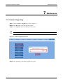
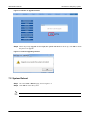
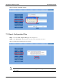
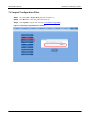


![Rii Mini-[2.4GHz] User`s Manual Ver:2.0](http://vs1.manualzilla.com/store/data/005760596_1-38a2c6f0785d9724a30239cfe3cd13aa-150x150.png)