1
Tallgrass
Technologies
Corporation
SOFTWARE
INSTALLATION INSTRUCTIONS
and
OPERATIONS MANUAL
FOR MODELS
TG-3006 TG-3012 TG-3020
TG-3135 TG-3170
T ALLGRASS reserves the right to make changes to the products described in this document in order to improve the design or performance
and to supply the best possible products . T ALLGRASS assumes no responsibility for the use of this product in any application, conveys no
license under any patent or other right , and makes no representation that
any application contained herein is free from patent infringement. Any
application contained in this publication is presented for illustration purposes only and T ALLGRASS makes no warranty that such applications
will be suitable for the use specified without further testing or modification. Reproduction of any portion of this publication without the prior
written consent ofT ALLGRASS is prohibited.
First Edition - June, 1983
© Copyright by Tallgrass Technologies Corporation, 1983
First Printing - July, 1983
Second Printing - August, 1983
Third Printing - September - 1983
Fourth Printing - October, 1983
Fifth Printing - December, 1983
Sixth Printing - March, 1984
TALLGRASS TECHNOLOGIES CORPORATION
Operation Manual for Models:
TO-300S
TO-30l2
TO-3l3S
TO-3020
TO-3l70
Copyright 1983 by TALLGRASS TECHNOLOGIES CORPORATION.
All Rights Reserved.
WARNING
This equipment generates, uses and can radiate radio
frequency energy.
As temporarily permitted by regulation,
it has not been tested for compliance with the limits for
Class A computing devices pursuant to Subpart J or Part 15
of FCC Rules, which are designed to provide reasonable
protection
against interference.
Operation of
this
equipment in a residential area is likely to
cause
interference in which case the user at his own expense will
be required to take what ever measures may be required to
correct the interference.
Please direct all comments concerning this manual to:
Tallgrass Technologies
11667 W. 90th St.
ONerland Park, KansAs 66214
Attn. Technical Support(Documentation
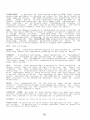
Preface
This guide provides a complete series of procedures for the
installation, configuration, and operation of the TALLGRASS
HardFile Subsystem. The user of this system must introduce
new hardware and new software as outlined in this guide.
This pUblication contains seven chapters:
Chapter One. Hardware Installation, covers selection of an
appropriate
power
source and operating
environment,
determination of hardware modification requirements, and
installation of the Interface Circuit Board.
Chapter Two. Software Installation, covers configuring the
HardFile,
selecting of system software options,
and
creating the integrated system "TALLGRASS Boot Diskette".
Chapter Three.
HardFile Diagnostics, describes various
tests and procedures available for operational use at the
HardFile System level.
Chapter Four.
Backing-Up On Tape,
instructs the user on
fundamentals of the tape system and user application
programs for tape backup.
Both Streaming and File-By-File
methods are discussed.
Chapter Five.
Having Trouble?, assists in locating and
correcting problems associated with installation and normal
operation of the system.
Chapter Six.
Maintenance,
describes
obtaining service on the HardFile System.
procedures
for
Chapter Seven.
Programming Notes, provides hints to the
new user for full utilization of your system.
I
NOTES
Introduction
This manual provides detailed procedures for
configuring, and operating your new system.
installing,
Your new TALLGRASS HardFile Subsystem brings powerful
Winchester mass storage technology and streaming tape
backup to the Personal Computer.
The options available
allow customized design of the HardFile configuration.
Wide versatility is available in adapting your system to
the needs and requirements of your own applications.
The installation and configuration exercises in this manual
will create a customized "TALLGRASS Boot Diskette".
Using
the procedures outlined, you will find your new integrated
system performing your specific application requirements
through this newly created "TALLGRASS Boot Diskette".
II
NOTES
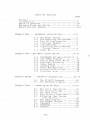
Table Of Contents
page
Preface .•.••..•...••.•.....•.............•••. I
Introduction •...•..•••.•..........•..•....•.. 11
Table of Contents •••.•..•.••.•.••.....•...••. 111
Warranty Terms and Policy .....•...••.•••••... VI
Specifications Summary ....••••.•••.....•..... VIII
Chapter On e
Hardware Installation ••.....••• 1-8
1-1
1-2
1-3
1-4
1-5
1-6
1-7
The Power Source •...•.•...••. l
The Operating Environment ••. 1
Your PC Configuration ..••... 2
Interrupt Request ...•••..•.• 3
I/O Addresses •.••...••••.... 5
Installing The Interface
Circuit Board ............. 5
Power Up •...•.•.•....••..••• 7
Chapter Two - Software Installation ............ 9-21
2-1
2-2
2- 3
2-4
2-5
2-6
2-7
2-8
2-9
Chapter Three
HardFile Diagnostics ••......• 23-29
3-1
3-2
Chapter Four
TALLGRASS Software Diskette •. 9
The TGSYS Program ........... 11
Ve r i f y Re a d Aft e r Wr i t e ..... 1 7
Duplicate Directory .•.•..••. 18
Cache Memory •••.....•...••.. 18
Landing Zone ..•.•...••••.••. 19
Drive Designations •.•.•.••.. 19
Allocation Unit Size .••..•.• 20
Directory Size ...•..•.••..•• 21
The UTILITY Program •..•..... 23
The SPEEDTST Program .•...••• 27
Backing Up On Tape •...•..•..• 31-47
4-1
4-2
4-3
4- 4
4-5
Why Use a Tape Dr i ve? ..•••.. 31
The Tape Cartridge .•..••.... 31
The Tape Drive •..•..••.•.•.• 32
Tape Drive & Tape Care ..••••. 33
Streaming Tape Versus
Fi le-By-Fi Ie .............. 36
4-6 The TAPE Program ••••.••••..• 36
4-7 The TGTAPE Program ...•...••. 44
4-8 TGBACKUP ..••••..••.•..•••••• 45
4- 9 TGRESTOR .••...•.•.••••••.•.. 46
4-10 TAPEDIR ....••.••.•.••.••••.• 47
III
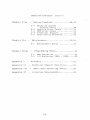
Table Of Contents
Chapter Five
Having Trouble? ••••.•••••... 49-52
5-1
5-2
5-3
5-4
5-5
Chapter Six
Chapter Seven
Replacement Parts ....•...•.. 53
Programming Notes ................ 55
7-1
7-2
Appendix II
HardFile System
Trouble Chart ............. 49
Audible Error Codes ••••••••• 51
OOS Error Codes ............. 51
Technical Support ......•.... 52
Application Software •..•.... 52
Ma i n tenance .......•.•........• 53-54
6-1
Appendix
(con't)
DMA Operation ................ 55
I/O Addresses 280H - 285H ..•• 55
Glossary •..•.....•.....•.......... 57
Technical Support Bulletins ...... 61
Append i x II I
Additional Operating Notes ..•.•. 63
Appendix IV
Interface Requirements ........... 65
IV
warranty Terms and Policy
~
TALLGRASS Technologies uses the highest qual i ty co mponents available today in manufacturing the industry ' s
finest mass storage systems. Our qual ity assurance program minimizes field component failure and provides
system reliability largely unavailable in the microcom puter industry. The TALLGRASS standard product warranty
covers parts and labor on all components excluding tape
cartridges for a period of 90 days from documented date
of sale. In most cases your authorized TALLGRASS supplier
wi 11 perform any required service.
IMPORTANT:
IN ORDER TO VALIDATE YOUR WARRANTY, FILL OUT
AND RETURN THE WARRANTY REGISTRATION CARD WITHIN III DAYS OF
PURCHASE DATE.
To return any defective equipment to TALLGRASS, a FAILURE
REPORT Form must be attached prior to returning it to the
factory.
In addition, a RETURNED MATERIALS AUTHORIZATION
(RMA) Number must be obtained from TALLGRASS. Any returned
equipment must be sent to TALLGaASS freight prepaid, and
the shipping container must prominently display this RMA
number.
The equipment will be Repaired or Replaced at the
option of TALLGRASS, and will be returned to you freight
prepaid.
Should TALLGRASS' examination and testing not
disclose any defect, TALLGRASS will so advise you and you
will reimburse TALLGRASS $75 for the testing and handling
expenses incurred.
For equipment incorporating a factory sealed enclosure
containing, but not limited to, disks and heads, this
warranty is deemed voided if the enclosure has been opened
or shows evidence of an attempt to be opened.
For
equipment
incorporating accelerometers to monitor for
mishandling, TALLGRASS reserves the right to automatically
exclude
from
warranty
coverage
any
drive
whose
accelerometer indicates excessive shock due to mishandling
or shipment in other than the original TALLGRASS-supplied
shipping containers.
Equipment should be shipped only in the shipping container
it was originally supplied in.
If replacement shipping
containers are required contact TALLGRASS Customer Services
to arrange for containers to be supplied.
CAUTION:
SHIPPING HARD DISK OR TAPE EQUIPMENT IN OTHER
THAN FACTORY-SUPPLIED CONTAINERS WILL VOID THE WARRANTY.
TALLGRASS will for no purposes be deemed to
liability with respect to data contained in any
placed in its possession.
v
have any
equipment
This warranty is contingent upon proper use in
the
application for which the equipment was intended and does
not cover equipment which was modifi~d without TALLGRASS'
approvel or which was subjected to unusual physical or
electrical stress.
EXCEPT FOR THE EXPRESS WARRANTY SET FORTH, TALLGRASS GRANTS
NO OTHER WARRANTY, EITHER EXPRESSED OR IMPLIED, ON EQUIPMENT, INCLUDING ALL IMPLIED WARRANTIES OF MERCHANTABILITY
OR FITNESS, AND THE STATED EXPRESS WARRANTY IS IN LIEU OF
ALL LIABILITIES OR OBLIGATIONS OF TALLGRASS FOR DAMAGES
INCLUDING,
BUT NOT LIMITED TO, CONSEQUENTIAL DAMAGES
OCCURRING
OUT OF OR IN CONNECTION WITH THE USE OR
PERFORMANCE OF TALLGRASS' PRODUCT.
VI
<
H
H
4
900K
12 Mbyte
10,000
GCR
4
900K
12 Mbyte
10,000
GCR
40 bits
18 bIts
8 b1ts
9.1 x 10E-13
1 x 10 E- 5
'I'G-3135
3
5
697
3,485
9
900K
4S Mbvte
10,000
GCR
3,600
8.33
5.09
10 . 00***
30
80
10,240
71,680
10,240
70,748,160
10,922
76,454
10,922
75,460,098
'I'G-3170
4
7
987
6,909
*** Including settling t1me
9
900K
45 Mbyte
10,000
GCR
3,600
8.33
5.09
9.00***
45
90
10,240
51.200
10,240
35,686 ,4 00
10,922
54,610
10,922
38,063,170
Without settling time
TG-3000, )100
15.0· X 5.5 " X 12.5"
TG-4000
9" X 7.5 " X 10.5"
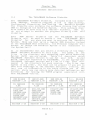
Power reqUIrements
107-127 or 214-254 VAC +/- 5\, 60 watts maXimum
EnVironmental reqUirements
ambient temperature
50-90 deg rees F. recommended
relative humIdity
8-80\ non-condensing
maXimum wet bulb
is degrees F. non-condensing
PhYSlcal slze (W x H x D)
Pmd
Pmc
CRC/ ECC length
DetectIon span
CorrectIon span
Disk and Tape Error Control
*Assumes use of certIfIed, defect-free qualIfied media
4
900K
12 Mbyte
10,000
GCR
3,600
8.33
5.09
3.00**
120
310
10,240
40,960
10,240
19,660,800
10,240
40,960
10,240
12,533,760
3,600
8.33
5.09
3.00**
85
205
10,922
43,688
10,922
20,970,240
'I'G-3020
2
4
480
1,920
~
10,922
43,688
10,922
13 ,368,528
'I'G-3012
2
4
306
1,224
Recoverable error rate* not more than one in 10E- 8
Non-recoverable error rate* not more than one 1n 10E-10
Tape Drive
Tracks
Transfer rate (bits/s)
Formatted capaCIty
Recording denSIty (RPIl
Recording code
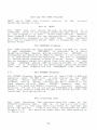
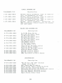
HardFile
'I'G-3006
Platters
1
Beads
2
Cylinders
306
Tracks
612
Storage Capac1ty (bytes)
-unformatted
per track
10,922
?er cylinder
21,844
per head
10,922
per drive
6,684,264
-formatted
per track
10,240
per cylinder
20,480
per head
10,240
per drive
6,266,880
Performance
rot. speed
3,600
avg. latency (msl
8.33
transfer rate (Mb/sl
5.09
seek, adjacent track (m.)
3.00**
seek, avg. (ms)
85
seek, max (ms)
205
Soecifications
NOTES
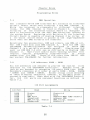
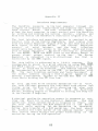
Chapter One
Hardware Installation
1-1
The Power Source
When installing the TALLGRASS HardFile System, consider
where to obtain power to operate the system.
Although the
HardFile is equipped with electronic switching power supplies that provide precisely regulated D.C. voltage for the
internal components, like your Personal Computer the HardFile is still not immune to power interruptions
or
disturbances.
Air-conditioners, water-coolers, copyingmachines
and
other motor-driven devices
may
cause
unreliable
operation if connected on the same power
circuit.
If you choose to operate your HardFile with an emergencyor "uninterruptable-" power supply system, be sure to
choose a system that switches to backup power within four
cycles or 64 milliseconds.
Before i nstalling the HardFile System, insure that the A.C.
power receptacle for your system delivers 107 to 127 volts
A.C. at 50 or 60 Hertz.
If the power available at the
receptacle is consistently lower than 110 volts, the HardFile can be adjusted to accommodate a low line condition of
98 to 118 volts.
This change must be performed by
qualified service personnel. If the A.C. line voltage input
to the HardFile is too high, the internal power supply
regulators will overheat; if the voltage is too low, power
supply output will be poorly regulated causing abnormal
HardFile operation.
Since the internal components of the
system operate from D.C. power, HardFile operation is not
dependent on power line frequency.
The A.C. power circuits of the HardFile System can also be
adjusted for European power in the range of 196 to 254
volts, 50 or 60 Hertz.
1-2
The Operating Environment
Like all electronic equipment, the reliability of the
TALLGRASS HardFile System can be influenced by certain
environmental conditions.
Below are some recommendations
to obtain maximum reliability and performance from your
HardFile System.
1
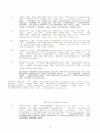
1.
When installing the HardFile System, be sure there
is adequate ventilation to allow air to flow freely
through the cabinet.
Avoid placing any object on
top of or underneath the HardFile cabinet that
would obstruct the flow of air. EXCESSIVE HEAT MAY
CAUSE THE HARDFILE ERROR RATE TO DETERIORATE.
2.
Place the HardFile System on a sturdy work surface.
Excessive vibration or shock can not only cause
errors, but may result in permanent damage to
HardFile System.
3.
When transporting the HardFile System, be sure to
pack it in the original shipping container. This
container is designed to protect the HardFile
System from vibration and shock .
THE WARRANTY WILL NOT BE HONORED ON EQUIPMENT THAT
HAS NOT BEEN TRANSPORTED IN A TALLGRASS SHIPPING
CONTAINER.
4.
1-3
Do not allow foreign objects to enter the HardFile
cabinet through the ventilation holes. Metal items
such as coins or paper clips will cause damage to
the internal components.
Your PC Configuration
At least 128K of RAM must be available in
Computer to operate the HardFile.
your
Personal
There
are several peripherals and
hardware
options
available for the PC which will enhance the operation of
your total system.
These accessories are not always
compatible with each other.
Sometimes these devices and
the HardFile may interfere with one another, causing
unreliable operation of one or both devices.
The HardFile
and the TALLGRASS Software can be adjusted to co-exist with
other devices that may be sharing the the I / O Channel
Interface Bus.
Slight alteration of the TALLGRASS Interface Circuit Board and a corresponding patch to the
TALLGRASS Software should allow the HardFile System and the
other devices to respond normally.
Refer to "Interrupt
Request" and "I/O Addresses" in this chapter.
Refer to
Chapter Seven, "Programming Notes", for a discussion of DMA
Channels.
The installation and operation manuals for the particular
peripherals or hardware options you are using in your
system usually contain compatibility information.
If in
doubt as to whether or not your current PC configuration is
compatible with the HardFile System, contact the manufacturers of the other devices used in your configuration.
2
~
Interrupt Request
1-4
The TALLGRASS HardFile System is shipped from the factory
set to use Interrupt Request #3 (IRQ3).
This I/O signal
is available at pin B25 of any of the I/O address
connectors.
If any other device in your Personal Computer
use s IRQ 3 , ( s u c has "COM 2 : " , s e ria lin t e r fa c e s, etc.) unreliable HardFile operation will result. If this situation
arises, either the device using IRQ3 or the HardFile will
have to be moved to one of the other IRQ signals.
If you
decide to move the HardFile System, refer to the following
s t e ps :
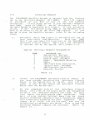
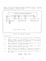
1.
Determine which IRQ signal is available for use in
your particular configuration.
Note that IRQ3
thru 7 are available for selection on the TALLGRASS
Interface Circuit Board.
IRQ 0 and 1 are dedicated
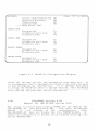
to internal use by the System Unit (Table 1.1).
Typical Interrupt Request Assignments
IRQ!
o
1
2
3
4
5
6
7
As.s.i"IHl.d
iQl.
System Unit Refresh
Counter Timer/Speaker
Orchid Tech. "PC-NET"
COM2: , TALLGRASS HardFile
COM 1 :
IBM Fixed Disk Controller,
Orchid Tech. "PC-NET"
IBM Diskette Controller
Parallel Printer
Table 1.1
2.
Locate the TALLGRASS Interface Circuit Board. If
you have already installed the Interface Circuit
Board in the System Unit of the PC, turn off the
power to your PC and remove the Interface Circuit
Board from the System Unit.
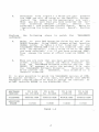
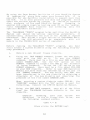
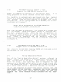
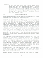
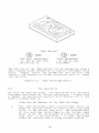
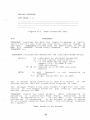
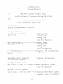
3.
On the component side of the Interface Circuit
Board, (the side of the board where the integrated
circuits are mounted) observe the block of pins
just above the gold-plated edge connector.
The
pair of pins located furthest away from the black
plastic interface connector has a solder less jumper
that electricly connects the pair together.
This
jumper will slide off the pin pair and can be
reinstalled on adjacent pin pairs. This is how the
Interrupt Request signals are selected.
Refer to
Figure 1.1 •
3
4.
Determine from Figure 1.1 which pin pair enables
the IRQ# you will be using on the HardFile System.
Install the jumper on the appropriate pin pair.
When you are sure that you have selected the correct
Interrupt Request
signal,
install
(or
reinstall) the Interface Circuit Board.
Refer to
"Installing the Interface Circuit Board", Section
1-6.
Perform
the
software:
following
steps
to
patch
the
TALLGRASS
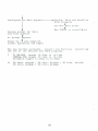
5.
Refer to your DOS Operation Guide for use of the
DEBUG Program. Using DEBUG, change offset location
XXXXH (refer
to Table 1.2 for location) in the
TALLGRASS TGTBIO.OOM file of the diskette that came
with the HardFile, from a value of 03 to the IRQ#
you have selected; i.e. if you have selected IRQ5,
then change the value at offset location XXXXH to
05.
6.
When you are sure that you have patched the correct
offset location, remove the "Write Protect" tab
from the TALLGRASS Software Diskette and use the
DEBUG "W" command to write the patched file onto
the TALLGRASS Software Diskette.
Reinstall the
write protect tab.
Remember, this diskette is a
"master" diskette.
It is also possible to patch the TALLGRASS version of CPM86 support software.
In this case, the DDT-86 (the CPM-86
debugger) program should be used to change the contents of
offset location XXXXH in the WINCH.CMD file.
SOFTWARE
VERSION
TG 3.XX
for PC-DOS
TG 4.XX
for PC-DOS
TG 3.XX
/CPM-86
TG 3.XX
/MS-DOS
FILENAME
TGTBIO.OOM
TGTBIO.OOM
WINCH.CMD
TGTBIO.OOM
01E2H
0172H
LOCATION
XXXXH
0172H
018BH
TABLE 1.2
Lt
Retaining
Bracket
~
/Plastic "0"
Connector
PI
o
+
Figure 1.1
This completes
signal.
1-5
TALLGRASS Interface Circuit Board
moving
the
TALLGRASS
Interrupt
Request
I/O Addresses
The TALLGRASS IBM-compatible Interface Circuit Board uses
I/O addresses 280H thru 285H to exchange data and commands
with the Personal Computer.
The use of anyone of these
I/O addresses by other devices or software may result in
unreliable HardFile operation. There is currently no software patch available to permit the use of alternate I/O
addresses
by the HardFile System.
For
programming
information relavent to I/O addresses 280H thru 285H consult Chapter Seven, "Programming Notes".
1-6
Installing the Interface Circuit Board
The following steps will require removal of the cover from
the System Unit of your Personal Computer.
5
1.
Turn off the System Unit of your Personal Computer
and remove the plug from the A.C. receptacle.
DO
NOT ATTEMPT TO INSTALL THE INTERFACE CIRCUIT BOARD
WHILE POWER IS APPLIED TO THE PERSONAL COMPUTER.
DOING SO WILL RESULT IN DAMAGE TO BOTH THE INTERFACE CIRCUIT BOARD AND THE PERSONAL COMPUTER.
2.
Remove the appropriate cabinet securing screws at
the rear of the Personal Computer, so that the
cabinet may be removed to expose the I/O Channel
Connectors near the rear of the PC chassis.
3.
Remove the screw that secures anyone of the blank
I/O channel retaining brackets to the rear chassis
of the Personal Computer.
Save the blank retaining bracket and the screw.
4.
Insert the TALLGRASS Interface Circuit Board into
any available I/O Channel Connector (except J8 of
the XT Personal Computer), making sure the edge
connector of the circuit board is properly seated
In the socket.
5.
Secure the retaining bracket of the Interface Circuit Board to the Personal Computer chassis with
the same screw that was used to secure the blank
retaining bracket.
DO NOT CHANGE THE DI SK DRIVE SWITCH SETTINGS ON THE
MOTHER BOARD OF THE SYSTEM UNIT.
TALLGRASS SOFTWARE PROVIDES FOR THE HARDFILE DRIVE DESIGNATIONS
AND IDENTIFICATION.
Installation of the Interface Circuit Board is now complete. The cover for the Personal Computer should now be
reinstalled
and secured and the power plug may
be
reinserted into the A.C. receptacle outlet.
Final Connections
1.
Position the TALLGRASS HardFile to the left or
right of the Personal Computer.
Avoid straining
the Interface Cable or pulling it taut .
Do not
attempt to lengthen the Interface Cable between the
Interface Board and the HardFile.
LENGTHENING THE
INTERFACE CABLE MAY RESULT IN DETERIORATION OF THE
SYSTEM ERROR RATE.
6
2.
Connect the Interface Cable to the black plastic
"D" connector protruding from the rear of the
Interface Circuit Board just installed in the Personal Computer.
3.
Connect the power cord into the provided socket
the rear panel of the HardFile System.
4.
Insert the plug on the other end of the TALLGRASS
power cord into the desired A.C. receptacle.
1-7
on
Power Up
1.
Turn on the power to the System Unit of the
Personal Computer and allow it to run through its
usual diagnostics.
Insert a DOS diskette into
floppy disk drive "A>" and boot up the system.
2.
Using the power switch located on the rear panel,
turn on the HardFile System and observe
the
following:
a.
The HardFile System will make a soft
ratcheting sound.
This is part of the
tape drive initialization sequence.
You
should
also
hear a
whirring
sound
eminating from the HardFile.
This is the
sound of the internal Hard Disk Drive
spinning up to speed.
b.
The "Decoder Error" lamp on the front
panel of the HardFi Ie System may be either
on or off.
The indication of this lamp
becomes valid only a f te r a Read/Write
Access.
c.
The
"Head Select" lamps will be
indicating that head zero is active.
off
In order to reduce the possiblity of erroneous control
signals being sent to the HardFile System, be sure to power
down the HardFile first and then the Personal Computer.
Powering up the system is most reliably accomplished by
turning on the Personal Computer before turning on the
HardFile.
7
This completes installation of the TALLGRASS Interface
Circuit Board.
The UTILITY program (Chapter 3) will allow
you to test the interface between the HardFile and the
Personal Computer after you have partitioned the HardFile.
Proceed to Chapter 2.
B
Chapter Two
Software Installation
2-1
The TALLGRASS Software Diskette
The TALLGRASS Software Diskette,
included with the Interface Package, contains programs to aid in Partitioning,
Configuring, Formatting, and Testing the HardFile System.
The Diskette also contains the software drivers that allow
OOS to recognize the HardFile System.
This sof'lware diskette should be used only as a "master" diskette,
that
is,
do not attempt to execute the programs directly from this
diskette.
Your
OOS master diskette and the TALLGRASS Software
Diskette will be used to create a new
"TALLGRASS Boot
Diskette" for use when you want to activate the HardFile
System. When you boot up on a regular OOS diskette instead
of tile TALLGRASS Boot Diskette,
the Personal Computer will
behave as though the HardFile System is not connected to
the System Unit.
It
is recommended tllat you obtain a directory of the TALLGRASS Software Diskette at this time.
The names of the
files
in the directory vary depending upon which Operating
System (O/S) you are using.
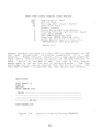
Table 2.1 describes which
TALLGRASS Software version to use for your O/S.
Listed
below each O/S supported by TALLGRASS,
is the appropriate
TALLGRASS Software version and a list of files
that will
appear
in the directory for each version.
The files may
appear in any order, but must all be present if you are to
take full advantage of the software features. Finally, the
last row of information in the table directs you to the
section where you can obtain more detailed information and
directions for running the TGSYS program associated with
each TALLGRASS version.
IDM PC-OOS
VERSION 1.10
IDM PC-OOS
VERSION 2.00
IBM CPM-86
VERSION 1. 00
TG VERSION
TG VERSION
TG VERSION
CPM-86 / 3.XX
TG VERSION
MS OOS / 3.XX
UTILITY.CMD
TAPE.CMD
TGSYS.CMD
WINCH.CMD
UTILITY.COM
TAPE.COM
COPYDUP.COM
TGTBIO.COM
TGSYS.COM
SPEEDTST.COM
UNFTTAPE.COM
3.XX
UTILITY.OOM
TAPE . COM
COPYDUP.COM
TGTDIO.COM
TGSYS.COM
SPEEDTST.COM
UN FTAP E. OOM
SECTION 2-2A
LXX
UTI LITY .OOM
TAPE . COM
COPYDUP.COM
TGTBIO.COM
TGSYS.COM
SPEEDTST.COM
UNFTAPE . COM
CONFIG.SYS
SECTION 2-2B
SECTION 2-2C
Table 2.1
9
T. I. MS-OOS
VERSION 1. 25
SECTION 2-2D
By using thc Tape Backup facilities of your HardFi Ie System
to temporarily store data under your current O/S,
it is
possible for one HardFile installation to support more than
one O/S.
It is also possible for data and programs filed
under the various operating systems to reside on separate
disk surfaces of the same HardFile System.
Changing to
another O/S simply requires booting your PC on the appropriate TALLGRASS Boot Diskette and accessing only the
specific HardFile surface(s).
The TALLGRASS "TGSYS" program helps partition the HardFile
System and adjust the various operating parameters.
It
automatically determines the size of the HardFile System
connected. This allows a single version of TALLGRASS Software (for the O/S selected) to be compatable with all
models in the TG3000/3100 series of equipment.
Before running the TALLGRASS "TGSYS" program, you must
first create a system diskette using the following step-bystep procedure:
1.
Obtain a new (blank) floppy diskette.
2.
Using the DOS FORMAT command, format the new diskette with the DOS on it.
To use the FORMAT
command,
there must be a file on your DOS diskette
named FORMAT.COM.
Use the "/S" option on the
FORMAT con~and to install the DOS as the diskette
is being formated.
To use the "/S" option on the
FORMAT command, there must be a file named SYS.COM
on your DOS diskette.
Refer to your DOS Operation
Manual for more detailed information on the use of
the FORMAT command.
You can verify that DOS has
been transferred to the new diskette by obtaining a
directory of the new diskette and observing the
presence of the file named COMMAND. COM.
When creating a system diskette under CPM-86,
the
"NEWDISK" command with the "$S" option is used for
formatting. Consult the CPM-86 Operation Manual.
3.
Using the DOS COpy command, copy all of the files
from the TALLGRASS Software diskette to the new
diskette.
Example:
Assuming
that your system
defaulted
to the A> floppy disk drive,
the following command syntax:
COpy * * B:
(t hen strike the RETURN key)
10
has
use
Under CPM-86,
f i 1 es .
Refer
more details.
4.
the "P I P" comma n dis use d to copy
to the CPM-86 Operation Manual for
After copying has completed, obtain a directory of
the new diskette.
The names of all of the TALLGRASS files should be present in addition to the
DOS file named COMMAND.COM (COMMAND.COM is not used
wi th CPM-86).
Hereafter, the new diskette just created will be refered to
as the "TALLGRASS Boot Diskette". You are now ready to run
the TGSYS Program to partition and configure the HardFile.
Proceed to the Section indicated in Table 2.1 for the O/S
you are using.
The TGSYS Program
2-2
Before running the TGSYS Program, a new boot diskette must
be created and the Interface Circuit Board installed
(Chapter 1).
The three main tasks of the TGSYS program are as follows:
1.
It divides the HardFile into more than one logical
disk drive (volumes) or allows the O/S to recognize
the HardFile as one large drive.
Combinations up
to 28Mb and up to seven logical drives are possible
depending on the TALLGRASS model selected.
You
have control over how the disk is divided.
Refer
to the equipment "Specifications Summary" on page
VIII at the beginning of this manual to determine
the number of surfaces in your HardFile.
2.
It allows you to manipulate the various HardFile
options (Verify Read After Write, Duplicate Directory, Cache Memory and Landing Zone) to best suit
your applications.
3.
It modifies the O/S (as neccessary) to
the HardFi Ie as you have configured it.
recogniz e
The following steps are required to start the TGSYS program:
1.
Place the TALLGRASS Boot Diskette into drive A) of
the Personal Computer.
Boot the system on the
TALLGRASS Boot Diskette and observe the following:
A.
The system will report the status of the
various options which should now all be
OFF.
11
B.
The system will display a CRC (Cyclic
Redundancy Check) time within the range of
11.45 to 13.98 ms (milliseconds).
C.
The system will check the HardFile motor
speed and display a hex number in the
range of D620 to D660.
D630 is typical
(D650 for TG 3135 / 70).
D.
The system will declare that the HardFile
configuration data is not available. This
is because the TGSYS program has not yet
modified
the
DOS to
recognize
the
HardFile.
NOTE:
IF THE HARDFILE IS NOT POWERED ON BEYORE
BOOTING, THE SYSTEM WILL REPORT A CRC TIME OF .1
MILLISECONDS AND THAT THE CRC GENERATOR IS BAD. IF
THI S OCCURS, IT WILL BE NECCESARY TO REBOOT THE
SYSTEM AFTER THE HARDF I LE I S POWERED UP.
THE SAME
CONDITION WILL OCCUR IF THE INTERFACE CABLE IS NOT
PROPERLY CONNECTED TO THE HARDFILE INTERFACE CIRCUIT BOARD AT THE REAR OF THE PC.
IN THIS CASE,
HOWEVER, A CRC TIME OF 0 MILLISECONDS WILL BE
DISPLAYED.·
After the system has displayed these messages,
it will
continue booting and finally ask for the date and time.
• This will only occur under the TALLGRASS 3.XX version.
The
TALLGRASS 4.XX version will report "Waiting for
Winchester Power-Up" for approxima tely two minutes, after
which time it will abort and default to non-modified DOS.
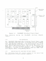
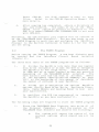
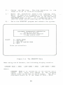
2.
Obtain an A) prompt on the display and
following command:
type
the
TGSYS
(then strike the RETURN key)
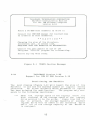
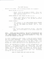
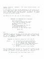
The program will respond with the message in Figure
2.1 that warns you to exercise care when running
the TGSYS program. Strike any key to continue into
the program.
12
TALLGRASS TECHNOLOGIES CORPORATION
HardFi(e Configuration Routine
for the IBM Personal Computer
version 4:04
Place a PC-DOS boot diskette i·n drive a:
Consult the IBM DOS manual for instructions
on creation of boot diskettes.
• • C AUT ION • •
Changing the size of the directory,
allocation unit, or sector size,
REQUIRES THAT THE HARDFILE BE REFORMATTED.
Consult the user manual on use of the
Tallgrass ' UTILITY' program for reformatting.
Strike any key when ready.
Figure 2.1
2-2A
TGSYS Caution Message
TALLGRASS Version 3.XX
Support for IBM PC DOS Version 1.10
Partitioning the HardFile
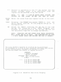
The next display (Figure 2.2) will report the size of the
HardFile in use and the maximum number of logical drives
permitted.
An arrow indicates which parameter or option
has been selected for modification.
The program only responds to the following keystrokes:
"+"
Adds the storage space of one logical drive (or
disk surface) to the storage space of the logical
drive pointed to by the arrow.
Every time the "+"
key is pressed, the storage capacity of another
logical drive will be added to the indicated drive
until all of the storage capacity of the HardFile
is assigned.
13
"_II
Similar in operation to the "+" key except this key
causes storage space to be subtracted from the
logical drive pointed to by the arrow.
NOTE: "+"
KEYPAD ON
AND
THE
" -" CAN BE KEYED FROM EITHER THE
RIGHT OR THE TOP ROW OF KEYS.
SPACE
BAR
Moves the arrow from one logical drive to the next.
"ESC"
Pressing the ESCAPE key causes TGSYS to exit the
partitioning portion of the program and go on to
configuration.
"H"
Stands for "HELP". Press i ng the "H" key a t any time
during the execution of the TGSYS Program will
display an explaination of the various options and
the keys tokes required to change parameters .
NOTE: PRESSING ANY KEY OTHER THAN THOSE DESCRIBED,
WILL CAUSE THE PC TO BEEP. THE COMBINATION OF CTRL
+ C WILL ABORT TGSYS AND RETURN THE DOS A> PROMPT.
The total lIardFlle catJacity of 12.53 mb may be partitioned
In Increments of 3.13 mb to form logically Individual qlsk drives.
Please combine/remove increments as desired to create
the desired number and slze(s) of logical drlve(s).
CXlMMANDS
+ Combine Increment
- Remove Increment
spacebar Move Indicator
' esc' Exit to next screen
H Help
--- )
Figure 2.2
3.13
3.13
3.13
3.13
mb
mb
mb
mb
for
for
for
for
DRIVE
DRIVE
DRIVE
DRIVE
ONE
TWO
THREE
FOUR
HardFile Partition Display
14
~
Take a few moments to experiment with the various combinations.
When you have decided on a combination·, press the
ESC key.
The system will record the information and
display the default HardFile configuration shown in Figure
2.3.
• It is recomnended that a hardcopy (printed or written) be
made of the Partition information. If it becomes necessary
to setup the HardFile after a system failure, this hardcopy
will provide the previous setup information.
Configuring the HardFile
The configuration portion of
following keystrokes:
SPACE
BAR
11
n
RETURN
"ESC"
TGSY~
responds
to
the
the
Moves the arrow from one catagory to another within
a group.
Changes the default parameter to the one desired.
Causes the arrow to move to the next group.
Pressing the ESCAPE key causes TGSYS to record the
configuration information in the newly created
TGCONFIG.DAT file on the TALLGRASS Boot Diskette.
The system will then exit the TGSYS Program and
enter the UTILITY Program.
The ESC key will only
cause this action when the arrow is positioned to
"Done". Refer to Figure 2.3.
If this is the first time TGSYS has been run, proceed to
Chapter Three, "HardFile Diagnostics" and refer to Section
3-1 for use of the UTILITY program. Upon completion of the
checkout proceedure outlined, choose the QUIT function and
press any key to reboot the system.
This allows the new
configuration data to be recorded on the HardFile. If this
is not the first run,
just choose the QUIT function and
press any key to reboot.
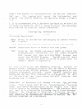
Described in Sections 2-3 through 2-9 are the various
options and parameters which must be set using TGSYS.
Of
these, "Verify Read After Write", "Cache Memory", "Landing
Zone" and "Drive Designations" can be changed from their
initial setting by running TGSYS again.
The HardFile does
not need to be reformatted following any of these changes.
However, the changing of "Duplicate Directory Option",
"Allocation Unit Size" or "Directory Size" REQUIRES THAT
THE HARDFILE BE REFORMATTED IN ORDER TO INSTALL THE REDEFINED DIRECTORY OR DIRECTORIES.
15
Press "h" for Help.
rOPT ION S :
---)
DRIVE ONE
Verify read-after-write
Duplicate directory
Cache memory
Landing Zone
Done I>ress ESC'
NO
NO
NO
NO
Designation
All oca t i on un it size
Directory size
C:
Designation
Alloca t i on un it size
Directory size
D:
Designation
All oca t i on unit size
Directory size
E:
Designation
Allocation unit size
Directory size
F:
2k
64
DRIVE TWO
2k
64
DRIVE THREE
DRIVE FOUR
'"
Figure 2.3
2k
64
2k
64
HardFile Configuration Display
After the various options and parameters have been set,
it
is recon@ended that a hardcopy (printed or written) be made
of the Configuration information.
If it becomes necessary
to setup the HardFile after a system failure, this hardcopy
will provide the previous setup information.
2-2B
TALLGRASS Version 4.XX
Support for IBM PC DOS Version 2.00
The steps to follow when running TGSYS are the same as for
TG3.XX/DOSl.10 (see Section 2-2A).
The main difference
occurs
in
the storage of the
configuration
data.
TG4.XX/DOS2.00 does not create the file TGCONFIG.DAT,
instead the information is stored in an already existing file
c a I led TGTB 10 . COM.
16
2-2C
TALLGRASS Version CPM-86 / 3.XX
Support for IBM CPM-86 Version 1.00
TGSYS for CPM-86 is presently in preliminary form.
being prepared for final release in the near future.
It is
The HardFile is automatically partioned into four logical
drives with preset allocation units and directory size.
In
it's present form the only choices to be made are drive
designations. After typing TGSYS and a RETURN, the following prompt will appear:
Enter drive designation for FIRST HardFile
(A,B,C,D,E,F,G,H,I,J,K,L,M,N,O) :
Each time you make a selection, the system will prompt you
for the SECOND, THIRD and FOURTH HardFile designations.
You must enter all four.
When the last designation is
entered, the TGSYS program will pause briefly, then display
a "Program Complete" message and the A) prompt.
At this
point
TGSYS is complete and the HardFile should be
formatted using UTILITY.CMD, similar to UTILITY described
in Chapter 3.
2-2D
TALLGRASS Version MS DOS / 3.XX
Support for T.I. MS-DOS Version 1.25
The steps to follow when running TGSYS are the same as for
TG3.XX/DOS1.I0 (see Section 2-2A).
2-3
Verify Read After Write
Use of the "Verify Read After Write" option, offered in
TGSYS, causes the HardFile to automatically read back the
data just written to the disk.
This occurs during each
write to disk.
The data read back is compared to the
contents of a 10K RAM buffer which is set aside in the PC.
If the comparison fails,
the system will rewrite the data
up to three times before a DOS error message is returned.
IT IS NOT POSSIBLE TO SELECT THE VERIFY OPTION AND THE
CACHE MEMORY OPTION TOGETHER. ANSWERING YES TO ONE CANCELS
THE OTHER. NOTE THAT VERIFY MAY BE TURNED ON AND OFF
THROUGH THE TGSYS PROGRAM WITHOUT REFORMATTING THE HAROFILE.
17
2-4
Duplicate Directory
The "Duplicate Directory" option in TGSYS allows the creation and transparent maintenance of a duplicate copy of the
regular directory and File Allocation Table (FAT) of each
declared drive.
This duplicate copy is updated each time
the regular directory is updated. The purpose of the
duplicate directory is to safeguard the contents of the
disk drive in the event of loss or damage to the regular
directory.
Since the directory/FAT is often the most
frequently accessed portion of the drive surface, and
because the read/write heads are often positioned over the
directory/FAT when the drive is not being accessed,
the
directory/FAT is especially vunerable to power loss, hardware failures and software mistakes.
The TALLGRASSsupplied COPYDUP command may be executed to restore the
directory if one of the following conditions occur:
If an abnormal format, or abnormal characters
1.
(garbage) appear in the directory.
error
If the DOS CHKDISK command indicates an
2.
3.
If the PC beeps during a directory/FAT access.
If the message "File Allocation Table is Bad"
occurs.
COPYDUP should not be used casually since it involves
possible destruction of recent directory information that
might not be present in the duplicate.
The duplicate
directory may also contain the same errors as the main
directory depending on the cause of the error condition.
4.
The "Duplicate Directory" option will significantly slow
the effective throughput of the HardFile whenever the directory is being accessed. NOTE: The HardFile must be
reformatted if Duplicate Directory is turned off or on
after initial formatting;
reformatting will erase all
stored data in the HardFile.
2-5
Cache Memory
Use of the "Cache Memory" option causes a 20K area of RAM
to be reserved in the PC for use as a disk buffer. This
improves file and record access time, in some applications,
by reducing the number of disk accesses per file.
Its use
is best suited for "seek intensive" applications,
i.e.,
those applications that require extensive reading of a
particular file, or portion of a file, to the HardFile.
IT IS NOT POSSIBLE TO SELECT THE CACHE MEMORY OPTION AND
THE VERIFY OPTION TOGETHER.
ANSWERING YES TO ONE CANCELS
THE OTHER.
CACHE MEMORY MAY BE TURNED ON OR OFF THROUGH
THE TGSYS PROGRAM WITHOUT REFORMATTING HARDFILE.
18
2-6
Landing Zone
The "Landing Zone" option offers an extra margin of protection against loss or corruption of the directory in those
areas that are particularly troubled by power fluctuations.
Use of the "Landing Zone" option causes the read/write
heads in the HardFile disk drive to automatically retract
after six seconds of inactivity to a track not normally
used to store data.
The user has the option of turning it
on or off, because use of this option may detract from
access time performance in some applications.
If the "Landing Zone" option is not enabled, the Landing
Zone action can be "manually" accomplished by running the
SPEEDTST program and choosing the L option, "MOVE TO
LANDING ZONE". This positions the read/write heads so that
the HardFile can be safely powered down.
Use of this
function does not effect the setting of the "Landing Zone"
option in TGSYS. NOTE: Landing Zone may be turned on or off
through TGSYS program without reformatting HardFile.
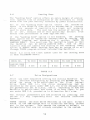
Table 2.2 lists the track number used for the landing zone
in each TALLGRASS model.
MODEL NO.
LANDING ZONE
TRACK # XXX
TG 3006
TG 3012
TG 3020
TG 3135
TG 3170
II 336
II 336
II 522
# 695
II 985
TABLE 2.2
2-7
Drive Designations
After you have completed setting the various HardFile options, continue configuring by pressing the RETURN key to
allow the arrow to be positioned to the first logical
drive. Under DOS 1.1, the drive designations may be
selected by the user; under DOS 2.0, the drive designations
are permanently set as C,D,E, and F, depending on how the
HardFile is partitioned, and there is no user input. If you
are under DOS 2.0, proceed on to Allocation Unit size.
The various parameters are now selected by pressing the
period (.) key repeatedly until the desired selection
appears.
TGSYS checks the Disk Drive Switches on the main circuit
board of the IBM System Unit to establish how many drives
are in the system.
This causes the system to default to
designations that are not already assigned to the system.
19
Example:
If you have one floppy disk drive, TGSYS will
assume that this drive designation is A:.
It also
assumes that B: is an imaginary drive. Therefore,
TGSYS will cause the first logical HardFile drive
to default to C:. Addtional drives defined by TGSYS
will be assigned remaining designations. TGSYS also
checks for the existance of hard disk drive C: in
the IBM XT.
If it is present, the first logical
drive will default to D:.
2-8
Allocation Unit Size
NOTE: SELECT YOUR A.U. SIZES CAREFULLY; CHANGING A.U. SIZES
REQUIRES THAT THE HARDFILE BE REFORMATTED.
PC-DOS, MS-DOS, and most typical disk operation systems
control the utilization of disk space by maintaining a
table, the File Allocation Table (FAT), which describes
file areas for the entire disk.
In the case of a 320K
floppy disk there are so few sectors (640) that each sector
may be represented by a separate entry in the FAT.
In the
case of a 20Mb HardFile, however, there are so many sectors
(38,000) and so few FAT entries available (4096 max. 12-bit
entries or 6K) that each entry is used to represent a
"cluster" of sectors. This cluster size, or Allocation Unit
size, is the minimum number of sectors which may be
assigned to a file. This will result in wasted disk space
when the file or file segment does not fill the Allocation
Unit assigned to it in the FAT. Allocation Unit sizes from
which you may select are 2K, 4K, SK, 16K, 32K, and 64K*.
Pressing the period key (.) with the pointer at Allocation
Unit will display these choices in succession as many times
as needed.
The optimum Allocation Unit size is usually one that is
closest in size to the files being written.
For example,
if the majority of files written are 14K in size, then an
Allocation Unit size of 16K is recommended. Although 2K of
space is no longer usable, file access time is improved.
If the loss of 2K is undesirable, smaller Allocation Units
can be used.
If 2K Allocation Units were chosen, seven 2K
units will be allocated to form the needed 14K.
Since the
linked Allocation Units are not necessarily in sequential
order on the HardFile, they must be searched for when
following the links.
This searching increases the file
access time thus decreasing system efficiency.
Allocation Unit size also affects FAT size.
Small Allocation Units require a larger FAT since there are more
Allocation Units to record. Larger Allocation Units result
in a smaller FAT.
The FAT will consume 1/2K to 6K of main
RAM space during each access.
·Under DOS 2.0, Allocation Unit sizes are limited to 2-3ZK.
20
2-9
Directory Size
The number of directory entries should be chosen carefully.
The number of files to be created must be equal to or less
than the number of directory entries.
If the directory is
too small, there may not be enough entries to handle the
files.
If the directory is too large, available HardFile
space will be reduced i.e., for every 64 directory entries,
approximately 2K is consumed by the directory space.
Once directory space is exhausted,
it cannot be increased
(or decreased) without reformatting that logical drive,
which will result in loss of access to the existing files
on the particular logical drive.
21
NOTES
22
Chapter Three
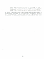
HardFile Diagnostics
3-1
The UTILITY Program
The UTILITY Program is provided as means of formatting and
testing the HardFile.
UTILITY uses the configuration
information that was entered by the user when running the
TGSYS program (Chapter 2).
UTILITY, when executed, will
attempt to find the configuration information in memory and
if absent from memory, on the TALLGRASS Boot Diskette.
UTILITY is the only means for installing empty directories
on the logical disk drives designated by the user when
running the TGSYS program.
Striking the "ESC" key at the completion of the TGSYS
Program will record the configuration information on the
TALLGRASS Boot Diskette and begin executing the UTILITY
program (Figure 3.1) automatically.
At this time the various UTILITY program features should be used to check the
integrity of the HardFile System.
The UTILITY program
features are defined below in the order in which they
should be executed following completion of TGSYS.
It
should be noted however, that the user may execute the
UTILITY program at any time by causing the system to
default to the TALLGRASS Boot Diskette and typing the word
"UTILITY" followed by a RETURN.
TAUGlASS TEI:lIDIroIES cmPCRATICN
Utility routine for the IBM Personal Cbmputer
12 Mb. Version 4:05
WRF E I DB-
Wri te test
... ERASES ALL INR:llMATICN CN HARD FILE •••
Read test
Checks ALL Information to see That It can Be Read
Fonm. t/Certi fy ... ERASES ALL INFCIlM\TICN CN HARD FILE •••
Examine specified track
Interface test
Directory re-initialize
Badtrack display
Q - Qui t
Enter your selection:
Figure 3.1
The UTILITY Menu
23
Each of the following functions (except Q) have a
display format.
Shown in Figure 3.2 is a sample
and a description of each field.
TALl.CRASS 'IKlDLCDIES CXI!POOATICN
Uti !tw"ti "~O,
~
1
Pass 0000
tho
similar
display
"<r_
l""~,_s_o_n_a_l_Corrp
__
TESTING Track 0001, Head 02
Total Errors 0000
(Press ESC Key to STOP)
Figure 3.2
Sample Display
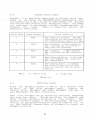
In Figure 3.2 :
A -
Name of the operation being performed is displayed.
B -
Track refers to the concentric circles of the
platter head on which the operation is performing
(analogous to tracks of a diskette).
C -
Head refers to the disk platter surface
the operation is being performed.
D -
Total
Errors ref~rs to the number
identified during the operation.
E -
Pass refers to the number of completed exercises
over all tracks on the head currently displayed.
F -
The area of the display where errors are listed in
the form:
Tr.k .... hd
1t.Er.r.
032 00
002
24
1.y.~e.
C
on
of
which
errors
Refer to Table 3.1 for the list of error types.
Error Types
Type
Description
CRe Error
Decoder Error
Read Error
Track Error
Write Error
C
D
R
T
W
I -
Table 3.1
INTERFACE TEST.
The INTERFACE test is used to
verify
the integrity of the HardFile interface.
It exercises the interface logic and performs a
read/write test on the buffer within the Hardfile.
The
interface
test does not write or
read
information from the disk.
Should the HardFile
fail the INTERFACE TEST, further testing is pointless until the cause of the failure is corrected.
The INTERFACE test should run for at least five
minutes without any errors.
You may exit the
Interface Test at any time by striking the ESCAPE
key.
R -
READ TEST.
The READ test is used to verify the
ability of the HardFile to read all disk drive
surfaces.
This test should be allowed to continue
until all tracks and surfaces have been tested.
This test is a non-destructive test,
i.e., it will
not harm the integrity of data stored on the disk
surfaces. When running the READ test for the first
time after the completion of the TGSYS program, the
system should display few if any errors owing to
the factory testing and formatting.
More than
twelve
errors during the read test indicates
possible damage in shipment.
Corrective action
will be required to resume HardFile operation.
F -
FORMAT/CERTIFY. This UTILITY feature allows you to
FORMAT and CERTIFY the HardFile surfaces.
The
Utility program formats the HardFile by writing and
reading test data to and from the internal disk
drive.
Each track is exercised thirty-two times.
If more than one error occurs, the "BADTRACK" is
identified
and automatically recorded in
the
"BADTRACK FILE". Although the HardFile is shipped
from the factory already formatted,
it is best to
re-certify the HardFile prior to actual
use.
FORMATTING takes about twenty to thirty minutes per
HardFile surface.
When completed, FORMAT writes a
new Directory and FAT.
25
After each logical drive has been formatted,
the system
will give the user an opportunity to add BADTRACKS to the
BADTRACK FILE.
Refer to the BADTRACK ~~P STICKER located
on the bottom of the HardFile (Figure 3.3).
If the FOR~T
feature has not
identified the BADTRACKS listed on the
sticker, these tracks should be entered manually.
It will
be necessary for the user to be familiar with the logical
disk drive to read/write head relationship.
HARDFILE
Head
BAD
Head
Track
TRACK
I Track
MAP
Head
Track
DRIVE SERIAL NO.
Figure 3.3
BADTRACK
~
STICKER
Up to twenty-four BADTRACKS may be identified by the FO~T
feature.
If the FO~T feature discovers more than twentyfour BADTRACKS, the program will terminate. This condition
is usually the result of shipping damage.
E -
EXAMINE SPECIFIED TRACK. This feature allows the
user to exercise a specific track for possible
weakness or defects.
THIS IS A DESTRUCTIVE TEST,
I.E., THE EXAMINE TEST WILL DESTROY PREVIOUSLY
STORED DATA. The user will usually be warned if an
area of the disk is occupied by a file.
EXAMINE
also provides the user with a means of making
entries to the BADTRACK FILE.
Any track, good or
bad, can be defined as a BADTRACK by using this
feature.
If examining a track displays an error,
the number of errors displayed will be one.
Since
two errors must occur before a bad track is stored
in the BADTRACK FILE,
the user should answer "Yes"
when the system asks for bad tracks that are not in
the display. The indicated BADTRACK should then be
typed in for proper recording in the BADTRACK
FILE*.
The
following features do not need to be performed
following the completion of TGSYS.
They can, however, be
run whenever needed to perform HardFile diagnostics.
26
D -
DIRECTORY RE-INITIALIZE. This feature allows the
user to to install a blank directory and File
Allocation Table. USING THIS OPTION WILL DESTROY
THE CURRENT DIRECTORY. To re-install a copy of the
current directory use the COPYDUP program discussed
in Chapter 2.
After the directory has been
installed, the system will ask for entries to the
BADTRACK FILE.
The user may at this time type in
other BADTRACKS in much the same way as the EXAMINE
feature.
W-
WRITE TEST. The WRITF. test is primarily
useful
as a quick test for the HardFile.
It works the
same way as the READ test except that test data is
written to the disk. THIS TEST DESTROYS DATA PREVIOUSLY WRITTEN TO THE HARDFILE. The WRITE test
also
writes a blank Directory and FAT
upon
terminat i on.
B -
BADTRACK DISPLAY. Using this feature allows the
user to examine the contents of the BADTRACK FILE
for the specified logical drive.
Q -
QUIT.
Exits the UTILITY program and
system to re-boot.
causes
the
* It is recommended that a hardcopy (printed or written) be
made of the BADTRACK FILE information.
If · it becomes
necessary to rebuild the BADTRACK FILE, this hardcopy will
provide the previous BADTRACK information.
3-2
The SPEEDTST Program
When the HardFile is activated by booting the Personal
Computer with the TALLGRASS Boot Diskette, the system performs a diagnostic sequence to check the motor speed and
the CRC time.
The SPEEDTST program allows checking the
motor speed and CRC time while at DOS level.
Simply
default to A> (or the floppy disk drive that contains the
TALLGRASS Boot Diskette) and type:
SPEEDTST
\then strike the RETURN key)
'--
The system will display
following features:
M-
a menu (Figure
with
the
Causes the system to check the motor speed of
disk drive within the HardFile.
the
27
3.4)
C -
Checks the CRC time.
The time should be
range of 11.45 to 13.98 milliseconds.
in
the
L -
Moves the read/write head to the Landing Zone.
Refer to Table 2.2 in Chapter 2 to determine the
track number of the Landing Zone in the particular
TALLGRASS model in use.
It is suggested that you
land the heads before powering off the HardFile.
Q -
Exits the SPEEDTST program and reboots the system.
TALLGRASS TECHNOLOGIES CORPORATION
Speed Test Routine
for the IBM Personal Computer
12 meg version 4:04
SELECT
MC L Q -
MOTOR SPEED
CRC TEST
MOVE TO LANDING ZONE
QUIT
Enter you selection:
Figure 3.4
The SPEEDTST Menu
When using the M feature, the following display results:
CURRENT BASE
xxxx
LAST GOOD
xxxx
LAST HANG
xxxx
where:
CURRENT BASE is an indication of the current motor
speed.
This value will change as the program
tracks minor variations in motor speed.
The value
displayed should be in the range of D620 - D658.
28
LAST GOOD indicates a value in the range of D620 D658. This value should not change in the display.
LAST HANG indicates a value in the range of D620
D658. This value should not change in the display.
A value outside of the given ranges usually means that a
problem has developed in the electronic tachometer circuit
of the hard disk.
Contact your service representative to
determine if a hardware malfunction has occurred and what
corrective action is required.
29
NOTES
30
Chapter 4
Backing Up On Tape
4-1
Why Use a Tape Drive?
As you become accustomed to using your TALLGRASS HardFile
System, a false sense of security may develop. With such
a large amount of storage capability available and the
speed and ease with which it can be accessed, the need for
a tape drive may, at first, not be apparent. Why use such
a relatively slow mass storage memory device when the
HardFile System is so well suited for the task?
The fact
is, no device is faultless, nor is it immune to failure. A
wise computer operator once said ,"If it's worth keying-in,
it's worth backing-up".
This is the primary purpose for
the tape drive, backing up the HardFile System as well as
the resident system drives. This is made possible thru the
use of the TALLGRASS provided routines; TAPE, TGTAPE,
TGBACKUP, TGRESTOR and TAPEDIR, all of which are explained
in detail within this chapter.
4-2
The Tape Cartridge
Before continuing, a tape cartridge (Scotch· Brand DC
Series or equivalent, see Section 4-4) will be required to
perform the various tests.
NOTE:
THE TAPE CARTRIDGE, ALTHOUGH WELL CONSTRUCTED, IS
QUITE DELICATE AND SUBJECT TO HANDLING AND STORAGE REQUIREMENTS.
IT IS STRONGLY RECOMMENDED THAT YOU FAMILIARIZE
YOURSELF
WITH SECTION 4-4, "TAPE DRIVE & TAPE CARE" AT
THIS TIME.
• Scotch is a registered trademark of Minnesota Mining
Manufacturing Co. (3M).
and
Write Protecting the Tape Cartridge
The tape cartridge is equipped with a write protection
mechanism designed to reduce the possibility of accidentally destroying data by over-writing it with new data or by
erasing it.
TALLGRASS Software carefully observes this
feature by requiring that the tape be "SAFE PROTECTED" to
be read from (as in an UNSAVE operation) and, conversely,
not "SAFE PROTECTED" prior to writing to it (Figure 4.1).
31
"Safe Button"
-@-
@-
SAFE
"NOT SAFE PROTECTED"
i.e. can be read from
and written to.
SAFE
"SAFE PROTECTED"
i • e. can be read
from ONLY.
The position of the "Safe Button" can be changed by using a
small regular blade screwdriver or similar instrument (thin
coin).
Simply insert the screwdriver into the slot and
rotate it 180 degrees (in either direction) until it snaps
into position.
Figure 4.1
4-3
Tape Cartridge Detail
The Tape Drive
As with the Tape Cartridge,
the Tape Drive is a delicate
instrument and should be treated accordingly.
Please take
a moment to familiarize yourself with Section 4-4 if you
haven't already done so.
Insertion and Removal of the Tape Cartridge
1.
The tape cartridge slides into the tape drive by
means of grooved tracks on either side of the tape
drive in the cabinet tape slot. The aluminum base
of the cartridge forms ridges on the bottom edge
which slide into the grooves on either side of the
tape slot in the tape drive.
A tape cartridge
should be inserted now to allow further testing.
32
2.
A spring-loaded door on the right front of the tape
cartridge swings open inside the slot as the cartridge slides into the grooves.
Little resistance
will be encountered as the tape is inserted the
first
inch into the slot.
At that
point,
resistance will be felt as the holding latch comes
into contact with the cartridge. Even pressure on
both sides of the cartridge will result in the
final seating and securing of the cartridge in the
tape drive.
The cartridge will then snap into
position.
When the cartridge is properly inserted,
it should be
secure and held captive by the spring latch.
Removal of
the cartridge will require a moderate pull sufficient to
overcome the spring latch.
DO NOT remove the cartridge
from the tape drive while the tape is in motion.
Tape Drive & Tape Care
4-4
The reliability of a device is only as good as the care
with which it is treated.
If you contaminate the gasoline
for your car with water,
it soon fails.
If you do not
clean the windshield, it becomes impossible to see through.
If you expose the oil to extreme temperatures,
it soon
breaks down.
So it goes with tape drives. The tape media
must mever be touched, the drive must be kept clean and the
operating temperature range always adhered to.
Presented
here is a set of guidelines which, when followed, will
insure high reliability and long life for your tapes, drive
and precious data they contain.
Tape Cartridge Handling, Preparation and Storage
Handling:
NEVER
-touch the recording media in any way.
NEVER
-manually
other.
NEVER
-place objects on the tape cartridge.
NEVER
-remove the cartridge from the drive while the tape
is in motion.
NEVER
-expose the tape cartridge to extreme temperatures.
advance
the tape from one
3~
hub
to
the
Preparation:
New tapes should be-conditioned prior to use.
Expose the tape to the
operating environment for a time equal to or
greater than the time away (up to maximum of eight
hours).
-Fast forwarded and Rewinded to repack
within the cartrige (CERTIFY does this
cally).
the tape
automati-
-certified by running CERTIFY.
Storage:
Tapes should always be-kept in their protective case and stored in a cool
dry place.
-operated under the following conditions:
Temperature:
41 to 113 F (5 to 45 C)
Relative Humidity:
20 to 80% noncondensing
Maximum Wet Bulb Temp.: 79 F (26 C)
-kept away from stray magnetic fields i.e., motors,
power transformers, magnetic tools,
telephones,
CRT monitors, etc.
-advanced to Beginning of Tape (BOT) or End of Tape
(EaT) before removal.
Remember,
the tape cartridge,
like a ll contact
media, has a useful life span and will wear out.
errors or abnormal audible noise may indicate a
cartridge or an impending failure.
Data on that
should be replicated on a new cartridge as
possible.
recording
Excessive
worn out
cartr i dge
soon as
Tape Tension
Proper tape tension is necessary for successful read / write
operation.
It is recommended that a cartridge be retensioned (by Fast forwarding and Rewinding) prior to use if
any of the following conditions apply:
34
1.
2.
3.
4.
Prolonged storage time
Storage at a temperature extreme
Physical shock
Excessive read / write errors
Tape Drive Cleaning
The read/write head assembly and integral tape cleaner
should be cleaned after the first two hours of tape movement when using a new tape cartridge.
Normal cleaning
should be done after every eight hours of tape movement.
Clean these areas with a lintless cotton swab moistened
with an IBM (or equivalent) head cleaning solution or
isopropyl alcohol if it is not available.
Care should be
taken to ensure that excess cleaner is not applied and that
all residue is removed. Head cleaning should be performed
with the power off (Figure 4.2).
The sensor within the opening of the Tape Drive that senses
the Beginning of Tape and the End of Tape should be dusted
off occasionally using a dry cotton swab.
See Figure 4.2
for the location of the sensor.
Tape Hole Sensor
Figure 4.2
Integral
Tape Cleaner
Assembly
Cleaning Locations
Recommended Tape Cartridges
3M / Scotch Brand
Use the DC-300XL to store up to 12Mb
Use the DC-GOOA to store up to 45Mb
(for the TG-3135 / 70 only)
Archive Corp.
Use the Model 09C to store up to 12Mb
35
4-5
Streaming Tape Versus File-By-File
When backing-up and restoring data using the Tape System, a
decision should be made between Streaming Tape or File-ByFile methods.
To backup an entire logical HardFile drive,
that is, ALL the files on that drive, the SAVE feature in
the TAPE Program (Section 4-6) should be used.
When using
SAVE to backup, the UNSAVE feature (also in the TAPE Program) must be used to recover the files from the tape.
Individual file recovery is not possible when backup was
accomplished using SAVE.
The File-By-File method allows individual files (or groups
of files by using global characters) to be backed-up
(TGBACKUP, Section 4-8) or restored (TGRESTOR, Section 4-9)
usi,ng the Tape / System.
If it is desired to backup all the
files of a particular logical drive (HardFile or Floppy)
and later recover them individually, use the *.* global
file designation.
In this way,
individual files can be
restored from the tape to any logical drive (HardFile or
Floppy) in the system.
The File-By-File method makes it
possible to backup to tape, files from one HardFile System
and restore them to another HardFile System.
This is
accomplished by backing-up with TGBACKUP, removing the tape
and replacing it in the new System, and then restor i ng
using TGRESTOR. TAPEDIR (Section 4-10) is provided to read
the directory of a tape track which was created using
TGBACKUP.
Prior to running TAPE, TGTAPE, TGBACKUP, TGRESTOR or
TAPEDIR, the computer must be booted up on a TALLGRASS Boot
Diskette as discussed in Chapter Two, "Software Installation".
4-6
The TAPE Program
Operation of the Tape Cartridge System should be checked
out following receipt of your new HardFile System.
Insert
a prepared tape cartridge (Section 4-4) into the slot.
Executing the TAPE program will result in the menu shown in
Figure 4.3.
36
TALLGRASS TB:lIDLOOIES CXlU'CRATICN
Cartridge Tape Backup Facility IEM Personal Computer
12 meg Version 4:06
RF S UVEC-
Rewind the tape
Fast forward
Save disk to tape
Unsave tape to disk
Verify tape can be read
Erase tape
Certify tape
Q - Qui t
Enter your selection:
Figure 4.3
The TAPE Menu
The CERTIFY Feature
CERTIFY is an extensive test of the tape drive, tape
cartridge, controller and interface electronics.
It is
also a DESTRUCTIVE exercise i.e.,
it writes and reads its
own test data to and fr~m the tape.
It is important,
therefore,
that the tape does not contain vital data as it
will be lost.
Select C for Certify tape. During the Certify exercise,
each action being performed will be listed on the lower,
left-hand corner of the screen.
Also, during any tape
motion, the screen will display position, error and other
informational codes (Table 4.1).
If any errors are
detected by CERTIFY, a listing will appear at the end of
the pass.
More than one error per tape track is unacceptable.
If this is the case, try a new tape. Cleaning the
tape drive will sometimes help.
The Certify exercise takes about ten or twenty minutes to
complete one full pass depending upon the drive capacity.
CERTIFY will continue to run indefinitely until interrupted
by depressing the "ESC" key.
One pass of CERTIFY is
usually sufficient to insure the integrity of the Tape
System.
37
POSITION CODES DURING TAPE MOTION
BOT
EOT
WZ
RZ
Beginning of Tape
End of Tape
Warning Zone (tape leader)
Recording Zone
Norma 1 record
Wrong Record/Missing Record
Missing Records (unrecorded tape)
Disk Seek ERROR
CRC ERROR Reading Tape
Decoding ERROR Reading Disk
Dummy Record used in lieu of a
BADTRACK on the Disk Drive
W
T
*
D
@
Table 4.1
Always advance the tape to either BOT (by Rewinding) or EOT
(by Fast forwarding) following completion of a
tape
session.
Power failure, surges, etc., may cause undefined
tape drive action which can result in the destruction of
data.
While at the BOT or EOT, the tape is in a region
where data is not written and is therefore safe.
The tape
cartridge can be safely removed from the drive at any time
that BOT or EOT is displayed and tape motion has ceased.
CEITIFYIOO
TAPE 'TRACK --0
PASS 00
\'cRITIID
'IOI'AL ER.R:RS 0000
• WZ RZ ••••••••••••••••••••.•••••••••••••••••••••••••••••
••••••• • ••• Wl EXJI'
FAST Fa'lARD EO!'
Figure 4.4
Typical display during CERTIFY
38
Other Features
In addition to CERTIFY, the TAPE Program provides other
features for tape operation which are described here.
REWIND and FAST FORWARD
These features are similar to those found on common home
cassette decks with one important difference: once initiated, they will run to completion with no provision to
stop them. Each takes roughly one minute to complete.
To SAVE or UNSAVE •.•
the
The
features SAVE and UNSAVE provide you wi th
capability of backing-up (SAVE) the contents of a HardFi Ie
saved
logical drive to tape and restoring (UNSAVE) the
data back to the HardFile.
In Chapter Two, "Software Installation", use of the TGSYS
Program was described in much detail.
It explained how to
partition the HardFile into different logical drive configurations.
There is a dLrect correlation between the
HardFile configuration and the use of SAVE/UNSAVE.
It is
important to realize that SAVE and UNSAVE operate on the
ENTIRE logical drive.
That is, an image of the data
recorded on the logical drive is written to tape, including
the BADTRACK File (Chapter 3), the Directory and the File
Allocation Table.
For this reason, tapes made on one
HardFile System cannot be unsaved to another
HardFile
unless the Drive Configuration and BADTRACK File are
identical. ALL the files of the particular logical drive
chosen are saved or unsaved.
Individual files cannot be
manipulated with SAVE and UNSAVE.
If individual file
access is required, the commands TGBACKUP and TGRESTOR
(Sections 4-8 & 4-9) should be used instead.
Listed in Table 4.2 are aspects of some different configurations.
Although Table 4.2 depicts a "12 + 12Mb "
system, the principle remains the same for other systems.
39
Possible Configurations for a
NUMBER OF
LOGICAL
DRIVE(S)
DESIGNATED
OF
SIZES
"
12 + 12Mb
"
wi 11
occup y
then
System
TAPE
TRACK ( S)
1
C:
4/4
C:
4
2
C: D:
2/ 4
2/ 4
C:
D:
2
2
4
C: D: E: F:
1/4
1/4
1/4
1/4
C:
D:
E:
F:
1
1
1
1
3
C: D: E:
1/ 4
1/4
2/4
C:
D:
E:
1
1
2
2
C: D:
1/4
C:
D:
3
3/4
1
NOTE:
The
drive designations shown here are only
examples; actual designations will depend on your system.
If there is one resident system drive (A:) then C:
through F: will be available.
If two (A: B:) then C:
through F:, if three (A: B: C:) then D: through G:. These
examples are typical cases, many more arrangements are
possible.
Table 4.2
For a " 12 + 12Mb" system, one tape is suffic i ent to SAVE
the entire contents of the HardFile. For" 12 + 20Mb" (or
larger) systems, two or more tapes will be needed if the
entire disk is to be saved.
In the latter case, the system
will prompt you when another tape is needed to complete the
backup.
You can see that the number of tracks needed holds the key
to the number of copies possible.
In other words,
if only
one track is required, then up to four copies of that
logical drive can be made on a single tape.
If two tracks
are required,
then two copies can be made.
Of course, if
more than two tracks
are required, then only one copy is
possible.
For larger systems,
"12 + 20Mb" and above,
this relationship is not as simple.
If the HardFile is
divided into four drives, a single drive (20Mb / 4 = 5Mb)
will necessarily occupy more than one tape track (12Mb / 4
= 3Mb).
4(1
The SAVE Feature
Select S for SAVE.
The following prompts will appear:
Which Drive? C, D, E, F
- Which drive do you want to SAVE.
This appears only if the HardFile is configured as
more than one drive.
ENTER NUMBER OF TAPE TRACK TO USE 0,1,2,3
Which tape track to start saving to.
For a
blank tape, select 0 for the most efficient
use of the tape.
BACKUP NUMBER
=
This appears in the TAPE RECORD ORIGIN REPORT
to help keep track of different tapes.
This
can be any number you choose (up to four
dig its) •
BACKUP NAME
- Can be any eight character string.
The tape
name will also appear in the origin report as
above.
NOTE:
TIlESE ARE ONLY EXAMPLES, TIlE DRIVE DESIGNATIONS AND
TAPE TRACK NUMBERS DEPEND ON TIlE SYSTEM YOU ARE USING AND
ITS CONFIGURATION.
TIlE TAPE TRACK NUMBERS 0-9 WILL BE
LISTED FOR LARGER TAPE DRIVES.
In order to SAVE to a tape track, it must be blank (erased)
and not SAFE PROTECTED.
Before the TAPE Program begins
writing data to the tape,
it will first read a small portion of the tape to determine if it has been erased.
If
either of these conditions are not satisfied, an error
messge will occur advising you of the pending condition.
After the information is saved,
it will automatically be
verified.
The position codes that appear have the same
meaning as in CERTIFY (Figure 4.4).
If during verification, an error has occured, the system will reinitiate the
VERIFY up to three times in an effort to obtain proper
verification.
If the final effort to verify is unsuccessful,
verification
is terminated and
the
following
message(s) will be displayed:
HEAD XX TRACK XXXX NOT SAVED ON TAPE
41
Press any key to continue.
The HEAD/TRACK numbers will be
correlated to their respective files and the following
message(s) will be displayed:
filename
THIS FILE IN DANGER
Make a list of these HEAD/TRACK numbers and endangered
files. Erase the tape and attempt the SAVE again. If these
same HEAD/TRACK and filenames reappear, this indicates the
files are damaged and cannot be saved.
These files are no
longer usable.
These HardFile HEAD/TRACK numbers should be tested using
the READ test and if found faulty, examined using EXAMINE
(both found in UTILITY, Section 3-1) and entered into the
BADTRACK file if neccessary.
The UNSAVE Feature
Select U for UNSAVE.
The following prompts will appear:
Which Drive? C, D, E, F
- As in SAVE.
ENTER NUMBER OF TAPE TRACK TO USE 0,1,2,3
- As in SAVE.
NarE:
THESE ARE ONLY EXAMPLES, THE DRIVE DESIGNATIONS AND
TAPE TRACK NUMBERS DEPEND ON THE SYSTEM YOU ARE USING AND
ITS CONFIGURATION.
THE TAPE TRACK NUMBERS 0-9 WILL BE
LISTED FOR LARGER TAPE DRIVES.
An origin report follows this (Figure 4.5) showing
tant information about the tape.
UNSAVINJ TAPE 10 DISK
DRIVE -------- D:
HEAD --------- 0
TAPE
'JRA(l{ ---
0
TAPE lIDXIID CRIGIN REPCffi'
Tape track ---------- 0
Tape number --------- 00001
Tape name ----------- test
Creation date ------- 06-11-83
Creation time ------- 10:30:33
Saved from drive ---- C:
1st records's # ----- 000
Figure 4.5 Tape Origin Report
42
impor-
If a BADTRACK File exists,
it will be listed and you will
be questioned by the system if you still want to UNSAVE.
If the tape to be unsaved was initially saved from the same
HardFile with the same BADTRACK file,
the data will be
unsaved intact.
If this is not the case, the data may be
damaged when unsaved.
You will also be prompted if the
origin reports differ (Figure 4.S).
If any errors occur during UNSAVE, the system will automatically
attempt
another UNSAVE.
After
the
third
unsuccessful attempt, the program will abort and list an
error report.
UNSAVIOO TAPE 'IO DISK
DRIVE -------- D:
HEAD --------- 0
TAPE 'IRACX --- 0
TAPE REXXlID ffiIGIN REPaIT
Tape track ---------Tape number --------Tape name ----------Creation date ------Creation time ------Saved from drive ---1st records's # -----
0
00001
test
OS-II-83
10:30:33
C:
000
Tape track 0 Has Records That Were Saved from Drive C:.
Are you sure you want to lNSAVE to Dr i ve D:? (Y/N):
Figure 4.S
Origin Report Error
The VERIFY Feature
VERIFY, unlike CERTIFY,
is a non-destructive test that
checks the current tape data for readability without
modifing it.
This test detects and displays errors using
the same format as CERTIFY (Figure 4.4 and Table 4.1). The
cartridge must be SAFE PROTECTED to run VERIFY.
The ERASE Feature
ERASE is a FULL-WIDTH ERASE over ALL tracks.
This erases
the entire tape at once.
No selective track erasure is
available.
As with Rewind and Fast forward, ERASE, once
initiated, cannot be stopped.
Consequently, think twice
before Erasing.
The cartridge must not be SAFE PROTECTED.
ERASE takes two minutes.
43
Exiting The TAPE Program
QUIT exits TAPE and returns
operating system in use.
control
to
the
current
Use of "ESC"
The "ESC" key will return the user to the menu or to a
different level of the program depending upon which point
in the program it is used.
Since some features
(Rewind,
Fast forward & Erase) are non-interruptable, there may be
no immediate response to the "ESC" key.
These features
will run to completion before "ESC" is reco~nized and tape
motion stops.
The UNFTAPE Program
The TAPE Program can only operate under the DOS for which
it was designed.
"UNFTAPE" is provided as a basic
HardFile-to-Tape Backup System alternative.
UNF TAP E is
unformated and makes no attempt to consult a file directory
or to understand drive designations.
The user is prompted
to decide which surface to save to which track.
UNFTAPE
has no recovery capability other then disk platter to tape
track.
UNFTAPE should NOT be used by PC-DOS or CPM-86
users. It is intended for use with other operating systems
that may lack support for the TALLGRASS tape devices.
4-7
The TGTAPE Program
The TGTAPE Program, which requir~s at least 128K of RAM and
operates under PC DOS 2.0,
is very similar to the TAPE
Program.
Those features common to both; Rewind, Fast
forward, Verify, Erase, Certify and Quit, operate in the
same manner as with TAPE.
TGTAPE, however, does not
support the SAVE and UNSAVE features.
Instead, refer to
Sections 4-8 and 4-9 on the use of TGBACKUP and TGRESTORE
(both also require 128K and PC DOS 2.0) which provide for
individual file manipulation.
The Interface Test
The tape Interface Test operates much the same as the
UTILITY Interface Test.
That is,
it tests all the interface logic to the tape drive just short of putting the
drive into motion.
It will run until interrupted by "ESC"
(Figure 4.7).
All position codes have the same meaning as
in Table 4.1.
4L!·
1ESTINJ INrERFICE
TAPE
TIlA(]{ --
0
Figure 4.7
4-S
Tape Interface Test
TGBACKUP
TGBACKUP provides you with the means to backup a particular file or files from any disk drive, hard or floppy, to
the tape.
TGBACKUP follows much the same format as the PC
OOS 2.0 "BACKUP" (Fixed Disk) Command.
The format for
TGBACKUP is:
TGBACKUP [d:][path]filename.ext /Tn [/S][/M][/D:mm-dd-yy]
where:
NOTE:
[] -indicates an optional parameter
d: -is the logical Source Drive
n -is the Destination Tape Track
number (0-3, 12/20Mb & O-S,
35Mb and above)
/S /M /D -operate as in PC ooS (see your
manual)
/A -add
(Append) is not supported
TGBACKUP
.,? -global characters are allowed
The filenames being backed-up to tape will appear on
display before they are transferred (copied) to tape.
by
the
The message "Track n has been loaded." signifies the completion of the backup operation and shortly thereafter
control returns to OOS.
TGBACKUP should be used
backed-up to a particular
cannot be backed-up to it.
protection is preserved.
to an already occupied Tape
will appear:
wisely.
Once information is
Tape Track, additional files
In this way, file overwrite
If an attempt is made to backup
Track, the following response
Tape needs to be erased
45
Before Erasing,
ENTIRE tape.
remember,
the
Erase feature erases
the
If the quantity of data being backed-up is too large to fit
on a single tape track, the overflow data will be automatically backed-up onto the next track. It should be noted
that the next track is now occupied, therefore,
it cannot
be used for further backup.
See Table 4.3 for the list of error messages.
TGBACKUP and TGRESTOR Error Messages
Bad Track Number
Out of Tape (insufficient space
on track for makeup records)
No more records on Tape
Bad Read
Write Error (cartridge may be
"SAFE PROTECTED")
Tape needs to be erased
No records on Tape (blank tape)
Table 4.3
TGRESTOR
4-9
TGRESTOR is used to retrieve files from tape, that were put
there with TGBACKUP. TGRESTOR follows much the same format
as the PC OOS 2.0 "RESTORE" (Fixed Disk) Command. The
format for TGRESTOR is:
TGRESTOR [d:][path]filename.ext /Tn [/S][/D]
where:
[] -indicates an optional parameter
d: -is the logical Destination drive
n -is the Source tape track number
(0-3, 12 / 20Mb & o-a, 35Mb and above)
/S /0 -operates as in PC OOS (see your
manua 1 )
.,? -global characters are allowed
The filenames being restored to the disk will appear on the
display AFTER each transfer is complete.
The following
message will appear at the beginning of the transfer:
.** Restoring files form tape track n ***
46
TGRESTOR can be used to restore the files from a tape to
any drive (HardFile or Floppy) desired, regardless of where
they were initially backed-up.
See Table 4.3 for the list of error messages.
4-10
TAPEDIR
To obtain a directory of a tape track:
TAPEDIR [path][filename.ext]/Tn[/S]
where:
[] -indicates an optional parameter
n -is the tape track number
/S -operates as in PC DOS (see your
manual)
.,? -global characters are allowed
47
NOTES
48
Chapter Five
Having Trouble?
5-1
HardFile System Trouble Chart
HardFile Power On Sequence Using IBM PC-DOS
Key:
~No
~ Yes
(unsuccessful operation)
(successful operation)
Power on PC
Inser~
TALLGRASS Boot Diskette
into Drive A:
Power
~on
HardFi Ie
Ra tChe\Vt i ng sound f rom------..-.;:>:> Check Power
Tape Drive
Connections
~:::lf::':"'i"
1
Whirring sound as--------~>~Check Power
hard disk spins up
Connections
to speed
W
Check Fuse
call~for
1
A: drive becomes
active as diskette
boots
Service
::;;.Consult PC troubleshooting guide
.I,
HardFiwle becomes active,----~::;;.;;.Correct Boot Disk? /
TALLGRASS Tech. HardFile
Correct TG Version?
BIOS message appears
R/W Ac\Vcess lamp lites
'IV
CRC Time = 11.45ms to
t
13.98ms*~CRC
Generator is bad
Ca 11 \V for Se r vic e
Options Listing appears
l'
Motor Speed
~
= D620
to
D660---~::;;.~Cannot
check Motor Speed
Examtne track ** ,UTILITY
49
~
Configuration Data
appears----~>~Config.
Data and HardFile
:::::::;::::·~::::'ig",.
1
System prompt for Date
and Time appears
'¥
A: prompt appears
Power Up i~ now complete,
normal operation can begin
For any further problems, consult the Sections
the use of the UTILITY an.d TAPE programs.
*
TI MS-DOS ranges 12.47ms to 14.11ms
COMPAQ DOS ranges 12.75ms to 13.16ms
Columbia ranges 11.1Sms to 12.75ms
**
TG 3006, #0132H
TG 3135, #02BSH
concerning
TG 3012, #0132H ; TG 3020, #OlEOH
TG 3170, #03DAH
50
Audible Error Codes
5-2
Because it is sometimes impractical to display error messages on the screen the TALLGRASS BIOS communicates with
the operator by using a series of coded beeps that eminate
from the PC when certain error conditions occur. The beeps
are patterned to correspond to binary representations of
numbered error codes.
Table 5.1 shows the pattern and
meaning of these codes.
Er ro r Code
Sound Pattern
Errol' Condition
1
SSSL
eRe Generator Timeout. The eRe
calculation did not occur within
the predetermined amount of time.
2
SSLS
Read Timeout. A Read operation
was initiated but a va lid preamble was not detected.
3
SSLL
DMA Timeou t.
A DMA transfer
was initiated but was unsuccessf uI .
4
SLSS
Head Stepping Error. A R/W head
position corrrnand was issued but
was unsuccessful.
5
SLSL
Head Homi ng Error. A command
was given to position the R/W
head to track 00 and was unsuccessful.
KEY:
S
Short beep
L
Long beep
Table 5.1
5-3
DOS Error Codes
Since the HardFile appears to DOS as
just another disk
drive(s), all DOS error messages apply.
Consult the
"Device Error Messages" and "Other Messages" sections of
your DOS manual for more information.
Some error messages can be especially confusing depending
upon when they occur.
"Divide Overflow", for example, may
occur during a HardFile directory or file access.
This
usually indicates damage to the Directory/FAT. Re-Initialization of the directory may be required (Section 3-1) or
the DOS "RECOVER" Command might be attempted to repair the
damaged directory.
51
5-4
Technical Support
TALLGRASS Technologies maintains a staff of specialists in
the Customer Service Department to help with any problems
that arise in the operation of your HardFile Subsystem.
The Technical Support Specialists can usually diagnose your
problem over the telephone and make recommendations on how
to obtain best HardFile performance.
This troubleshooting
service is also available outside of the U.S. via telex.
When calling for assistance on the telephone, if possible,
move the telephone near to your computer s~stem. This will
allow you to issue test commands to your system in order to
determine the source of the problem.
Below is a suggested list of items to have
expedite the troubleshooting process.
on
hand
to
1.
The model and serial numbers of your HardFile.
2.
The version number of the TALLGRASS Software you
are using.
This number can be found on the label
of the diskette that was sent with the unit.
The
version number on the screen may not correspond
with the release version number printed on the
diskette.
3.
The type and version number of the Operating System
and Application Software you are using.
4.
A list of options or other peripherals currently in
use with your system.
5-5
Application Software
Many types of software and software packages are available
on the market today.
Understandably, not all are compatible with each another.
If you experience problems using
the HardFile with different software packages, consult the
Sections on DMA operation and I/O addresses (7-1 & 7-2).
Some programs make use of the Interrupt System and/or DMA
which can create conflicts between the program and the
HardFile.
TALLGRASS' software modifies the BIOS portion of the O/S so
that it can recognize the HardFile.
Any application software that also modifies BIOS may create system conflicts.
If still in doubt, contact the software supplier your
Authorized TALLGRASS Dealer.
52
~
Chapter Six
Maintenance
Replacement Parts
6-1
Parts List for the TG-3000/3100 Series
CABINET PARTS AND HARDWARE
TALLGRASS PIN
0-64-1064-1206
0-64-1064-1212
0-64-1064-1220
0-64-1064-4535
0- 64-1064-4570
1-75-1035-1000
1-75-1035-1200
1-76-1035-1202
1-76-1035-1301
1-76-1035-1302
8-98-2031-0630
Descr i pti on
Front panel inlay, TG-3006
Front panel inlay, tG-3012
Front panel inlay, TG-3020
Front panel inlay, TG-3135
Front panel inlay, TG-3170
Top cover series, TG-3000/3100
Bottom chassis series, TG-3000/3100
Heatsink, regulated power supply
Left "T" controller support bracket
Right "T" controller support bracket
Replacement hardware package*
*The replacement hardware package contains:
6 ea. Machine screw, 6-32 x 1/4"
3 ea. Tape drive mounting spacer, 3/8" dia.
6 ea. #6 flat washer
6 ea. #6 internal tooth lock washer
6 ea. Hex machine nut, 6-32 x 5/16"
3 ea. Fuse, MDL 3/4 amp. slow blow
POWER SUPPLY ASSEMBLIES
TALLGRASS P /N
8-96-1999-3000
8-99 - 1071 - 9000
8-99-1099-0014
8-99-1999-0014
~
Description
BackpaneJ regulated power supply assembly and transformer for TG-3000 series*
Switching power supply for units equipped
without regulated power supply
assemblies.
Regulated power supply
Disk +5/12 Volts
Regulated power supply
Tape +5/24 Volts
*Part
number 8-96-1999-3000 backpanel regulated power
supply consists of part numbers 8-99-1999-0014 and 8-991099-0014 regulated power supplies, fuse holder, power
switch, power transformer (wired for U.S. power), and the
line cord. Note that part numbers 8-99-1999-0014 and 8-991099-0014 may be purchased separately.
53
CABLE ASSEMBL I ES
TALLGRASS PIN
1-27-2025-0934
1-27-2025-1220
1-27 - 2025-1350
1-27-2025-3634
Description
Ribbon cable assembly, disk to contr o l ler, 34 conductor (9 inch)
Ribbon cable assembly, disk to control ler, 20 conductor (12 inch)
Ribbon cable assembly, tape to controller, 50 conductor (13 inch)
Ribbon cable ass embly, controller to
DMA interface circuit bo a rd, 34 conductor (36 inch)
MAJOR SUB-ASSEMBLIES
TALLGRASS PIN
Description
0-77-1023-2006
6.25 Mb Disk Drive
Miniscribe Model 2006
12 Mb Disk Drive
Miniscribe Model 2012
20 Mb Disk Drive
Miniscribe Model 4020
35 Mb Disk Drive
CDC MODEL 9415-5
70 Mb Disk Drive
Vertex Model ??1?
Tape Drive TG-3000 series
Archive Model 9020B
Tape Drive TG-3100 series
Archive Model 9045B
Analog Circuit Board
Buffer Circuit Board
DMA Interface Circuit Board
0-77-1023-2012
0-77-1023-4020
0-77-1069-9415
0-77-1???-????
0-78-1039-9020
0-78-1039-9045
8-99-1999-0011
8-99-1999-0012
8-99-1999-0013
ACCESSORIES
TALLGRASS PIN
0-65-1064-0250
0-65-1064-2181
8-88-1035-0007
8-88-1035-0008
8-90-2033-3000
8-93-2060-3006
8-93-2060-3135
8-93-2060-5000
Description
"Wired For 250 VAC" Sticker
(pkg. of 6 ea.)
Bad Track Map Stickers
Beige Front Panel Touch-Up Paint
Gray Cabinet Touch-Up Paint
Shipping Container TG-3000/3100 series
Service Manual TG-3000 series
Service Manual TG-3100 series
Spare Parts Order Form
54
Chapter Seven
Programming Notes
DMA Operation
7-1
The standard TG-09 IBM Interface Kit contains an Interface
Circuit Board which uses Interrupt 3 and DMA Channel 3.
While the interrupt is strappable to different
interrupt
lines, the DMA Channel is fixed on Channel 3.
The DMA
circuitry of the Interface Circuit Board is designed to
work in conjunction with the 8237 DMA Controller located on
the system board. Beginning with Revision H, the Interface
Circuit Board is capable of sharing Channel 3 by virtue of
a tri-state driver which is placed in the high-impedance
state when the DMA circuits are disabled.
Relatively few accessories, IBM and others, use DMA at all.
The IBM fixed disk uses DMA Channel 3.
Both the IBM and
TALLGRASS hardware/software are designed to share DMA
Channel 3 in a serially re-usable manner.
Single-user O/S
such as IBM DOS 2.0 will see no difficulty in sharing DMA
Channel 3.
Multi-user and/or multi-tasking systems will
require
special programming considerations
to
avoid
competition for DMA.
Users of O/S other than IBM PC DOS
may contact TALLGRASS for further information.
7-2
I/O Addresses 280H - 285H
Six I/O addresses are decoded to provide the control lines
required by the TALLGRASS controller.
Address lines AO
thru A9 are decoded to recognize I/O ports 280H thru 285H.
Secondary responses will occur at ports 680H - 685H, OA80H
- OA8SH and OE80H - OE8SH.
Solder straps allow decoding
of these different addresses, however, no software patch is
presently available. When used with the TALLGRASS controller, the I/O ports are assigned functions as defined in
Table 7.1.
I/O Port Assignments
I/O Port
280H
281H
282H
283H
284H
285H
Read
Write
Status
Data
CRC byte
<Reserved>
IX'v1A.lntrpt. Status
<Reserved>
Table 7.1
55
Control-2
Data
Address MSB (CRe select)
Address LSB
IX'v1A, Intrpt. Enable
Control-1
NOTES
56
Appendix I
Glossary of Terms
ALLOCATION UNIT
The unit of disk media (in bytes) which
is used by DOS (and other operating systems) to calculate
the availability and usage of disk space.
It is the minimum number of bytes of disk media alloted to each directory
entry or file name.
The allocation unit is the basis of
all entries in the File Allocation Table (FAT).
APPLICATION
A program or series of programs
that
perform(s) functions specific to a user's needs e.g., stock
market analysis, inventory control and order-entry.
BIT A binary digit (i.e., a logical "1" or "0".)
BOOT
(bootstrap loading) The process by which
grammed loader or operating system is installed
CPU's main memory.
Also known as IPL or Initial
Loading.
BOT
a proin the
Program
Beginning of tape.
BUFFER
An area of storage (or memory) that temporarily
holds data to be transferred to or from the CPU or any
other I/O device.
BYTE
A group of eight bits (or binary digits).
CACHE MEMORY
A method of improving the effective
transfer rate to and from the CPU, essentially hidden
transparent to the user.
The likely reuse of
requested by the CPU is anticipated by copying
specific data into an area of main memory that has
allocated as cache memory.
CPU
data
and
data
that
been
Central Processing Unit.
CRC
(Cyclic Redundancy Check) A method of data validation
in which all characters of a data block (10 K bytes) are
treated as a serial string of bits representing a binary
number.
This number is divided (modulo 2) by another
binary number, which is determined by controller hardware,
yielding a remainder which is the CRC character.
This CRC
character (40 bits) is compared to a check character which
has been calculated by the controller in a similar fashion.
If the result of this comparison is true, the data is
assumed correct,
if false,
the controller repeats the
operation.
CRC TIME The amount of time required to generate a CRC for
a single data block.
57
DIRECTORY
A portion of disk media used by DOS (and other
operating systems) to create an index for the data found on
that logical drive. The DOS directory is organized by file
name.
Each entry in the directory created by DOS is 32
bytes long and contains the file name (and extension, if
one exists), an attribute byte (designating hidden or
"system" files),
the date the file was created, the first
Allocation Unit number, and the file size in bytes.
DMA (Direct Memory Access) A technique of data transfer in
which the host CPU will issue a single transfer request for
a large block of data.
The CPU does not service the
peripheral device again until the entire data block has
been transferred, allowing it to perform other operations
being requested. The TALLGRASS DMA controller provides for
chaining, which permits multiple blocks of data to be
transferred to main memory with a single CPU command.
EOT
End of tape.
ERROR
Any condition which exists in the hardfile system
that may cause the improper reading or writing of data.
FORMAT
A special non-data, sync character or "preamble"
which is encoded by the controller in order to separate
data blocks. The "preamble" or format character (typically
128 bytes long) is written immediately preceeding each 10K
byte data block.
GCR
(Group Code Recording) A method of data encoding in
which each byte of data is split into two (2) four bit
nibbles and then translated into a five (5) bit code by
accessing a translation table (found in controller ROM).
This "encoded" data is then written onto the disk media as
a serial string of bits. The reading of data from the disk
media employs the inverse of the GCR write process.
The
GCR process is the HardFile Systems' first level of error
detection.
HEAD
The component(s) of the disk or tape drive which
convert electrical energy into magnetic energy (or viseversa) necessary for the transfer of data to and from the
disk media or magnetic tape.
LANDING ZONE An area of disk media where no data can ever
reside, which provides a location for positioning the heads
when the system is to be transported or powered down.
NIBBLE
A group of four bits (or 1/2 of a byte).
PARTITION A portion of disk media designated as one logical drive.
A partition is always greater than or equal to
one surface of disk media.
58
PLATTER
A component of the hard disk drive which rotates
on a spindle, and consists of two (2) surfaces of disk
media.
RZ
(Recording Zone)
which data resides.
The portion of magnetic
SECTOR
The amount of disk media required
bytes (typically) of data.
to
tape
upon
store
512
TRACK
Specific concentric circles of disk media or longitudinal lines of magnetic tape upon which the read/write
access heads are positioned when transferring data to or
from the drive(s).
WZ (Warning Zone) That portion of magnetic tape upon which
data cannot reside, whereas beginning or end of tape is
emminent.
59
NOTES
60
Appendix II
Technical Support Bulletins
61
NOTES
62
Appendix III
Additional Operating Notes
Drive Size-- Under IBM's implementation of DOS 2.0, devices larger than 30 Mb are not possible since no provision
is made in the DOS bootstrap for use of sectors larger than
512 bytes.
This requires that 35 and 70Mb HardFiles be
partitioned into volumes of 30Mb or less.
Command Compatibility-- Some of the DOS commands,
for
example, FORMAT, DISKCOPY and DISKCOMP, will not work in
conjunction with the HardFile, or may work with confusing
results.
DISKCOPY and DISKCOMP are designed specifically for use
with diskette devices only and must not be used with HardFile devices.
FO~~T
is also specifically for use with diskettes only,
and shoulp not be used where a HardFile device is designated A: or B:.
FORMAT contains its own private drivers
for the diskette format functions per se, but when FORMAT
attempts to install the directory and/or system files on
the new diskette it uses BIOS and attempts to reference the
diskette as A: or B: without realizing the A:/B: may now be
redefined as a HardFile device.
As such, FORMAT will
install a new floppy directory on the existing HardFile
device and destroy the HardFile's directory.
To be safe, FORMAT, DISKCOPY and DISKCOMP should never be
used with the modified system made by TGSYS.
Instead,
always reboot with unmodified DOS before using these
programs.
63
NOTES
64
Appendix IV
Interface Requirements
The HardFile connects to the host computer through its
integral 34 conductor ribbon-cable and separate host Interface Circuit Board.
The host Interface Circuit Board
allows the host computer to exert control over the HardFile
by setting and sensing the various control, status, and
data bits within the HardFile's controller (Figure A-IV.I ).
The host interface and operating system is required to set
control bits in two Control Registers, read status bits
from the Status Register (Figure A-IV.2) and read and write
data bytes in the track buffer.
The Control Registers
consist
of
octal latches,
and the host
interface
essentially has direct access to the data,
latch and clear
pins on these re~ers. ~ noise filtering is performed
on the RESET, WCIS and WC2S lines on the Buffer Board to
ensure clean, proper control on the bus.
The Status
Register is connected to a bi-directional bus that is
controlled by the RSE signal.
The
data buffer is addressed by a 14-bit counter.
This
be preset to a given address by using CLR, WAHS
and WALS signals.
In this manner any byte(s) of a record,
sector or track may be accessed.
The address counter may
be incremented by a pulse on the CLK,
in conjunction with
CEo
The host interface performs and "auto-increment" of
the buffer address during a read or~ite o~ation ~
sending simultaneous strobes to the CLK and ROE or WDS
line~' while holding the CE line low.
coun~may
To step the disk drive actuator mechanism "in" or "out",
the host CPU must generate the individual step pulses and
timing using the Step bit while observing the step rate
specifications of the disk unit.
With the Self-Step
option, stepping begins in response to setting the Step bit
in the Control-2 Register.
A physical read/write operation occurs in response to setting the Start bit in the Control-2 Register.
The R/W
operations begin automatically in response to Start, and
the host may monitor the R/W Complete bit in the Status
Register while waiting for the operation to terminate.
During data transfer of a R/W operation,
the host should
not accesss the track buffer of the addtess counter since
that action would disrupt the proper functioning of the
controller during the R/W operation.
65
PIN#
1- 8
10
DESCRIPTION
IN / OUT
LOADING
Data Bus for all data II status.
Goes minus during Seek, Read,
Wr i te or CRC generate .
Read CRC enable. Gates selected
CRC byte onto bus.
Read STATUS enable. Places 8
bit s of Controller or Drive
status on the bus.
Read DATA enable. Places next
byte in the Bu ff e r on the bus.
Write CXlNTROL-l strobe. Stores
data which is on the bus Into
Control-l Register.
Write DATA strobe. Stores data
at present addressed Bu ff e r
location.
Write Address High. Used with
CLK to ·preset MSB address into
Bu f fer Address Counter.
Write CXlNTROL-2 strobe. Stores
data which Is on the bus Into
Control-2 Register.
Write Address Low. Used with
CIK to preset LSB address Into
Buffer Address Counter.
CLOCK used to Count & Preset
Address Counters lor the Data
Buffer.
Clears Control Registers.
Count Enable. Enables Buller
Address Counters to respond to
CLK. Used by Host i£! AUTOINCREMENT leature ol WDS II ROE.
Bi -D i r
Output
4 LSTTL
Input
2 LSTTL
Input
2 LSTTL
SIGNAL
DO - 07
BUSY
12
RCE
14
RsE
16
ROE
18
WCIS
20
WDS
22
WAHS
24
WC2S
26
WALS
28
CLK
30
32
RESET
CE
N/ A
Input
2 LSTTL
Input
1 LSTTL
Input
1 LSTTL
Input
2 LSTTL
Input
1 LSTTL
Input
2 LSTTL
Input
1 LSTTL
Input
Input
1 LSTTL
1 LSTTL
9,11,13,15,17,19,21,23,25,27,29,31 II 33 are all GROUND Returns
Figure A-IV.l
I/O Signal Defin"ition
Regllter.
STATUS -l
REGISTER
CONTROL-l
SELECT
REOI STER
(X)NTROL-2
START
REO : STER
Figure A-IV.2
Register Definition
66
-----'
NOTES
NOTES
•