1
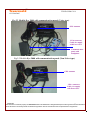
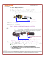
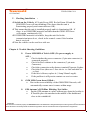
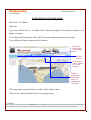
Transworld
TW-PD-USM-1V01-
AVLV04.DOC
TM
TM
Transworld
Transworld
DIGITAL ELECTRONICS DIVISION
DIGITAL ELECTRONICS DIVISION
Mobile Eye AVL-2000
USER MANUAL
Service Help Desk Telephone: +91 9960322240
Confidential
This document is exclusive property of TRANSWORLD. Not to be distributed or divulged without prior written agreement.
TM
Transworld
TW-PD-USM-1V01-
AVLV04.DOC
User Manual for AVL
Revision: 1.04
Date:
20th Feb 2008
Reference: TW-PD-USM-1V01-AVLV04.DOC
Document History
Index
1.01
1.02
1.03
1.04
Date
22 May
2007
23Nov
2007
28Jan 2008
20 Feb
2008
Version
Creation
Author
Yuvraj Jadhav
Voice call Modification
Yuvraj Jadhav
Fleetview Functionality
Fleetview Functionality
Yuvraj Jadhav
Yuvraj Jadhav
PURPOSE: The aim of this document is to provide complete information utility point of view
of the product Mobile Eye-2000 A/AP to TRANSWORLD customers/users.
COPYRIGHT
This document is copy righted with all rights reserved. No part of this manual
may be reproduced in any form without prior consent of TRANSWORLD. The
information in this document is subject to change without notice.
TRANSWORLD reserves the right to make revisions to this document and the
product described herein without obligation to notify any person or entity of
* Table of Contents *
any such changes.
Confidential
2
This document is exclusive property of TRANSWORLD. Not to be distributed or divulged without prior written agreement. All the information
In the document is covered by mutual non disclosure agreement .The user is deemed to have accepted the terms of agreement.
TM
Transworld
TW-PD-USM-1V01-
AVLV04.DOC
Part-I
AVL Unit Installation
Chapter No.
Contents
Page No.
I.
Before Operating
I. Pre-Installation Inspection……………………………........ 4
II. Recommendations…………………………………………. 4
II.
Getting Started
I. Package Contents………………………………………….5
II. Specifications……………………………………………… 5
III. Components of AVL Unit………………………………… 5
2.1 Mobile-Eye 2000Non-voice type
2.2 Mobile-Eye 2000with communication panel
Unit Installation Procedure
I. Vehicle Mounting of AVL Unit………………………….. 7
II. Power Supply Connection with Unit……………………… 8
III. Battery connection………………………………………. 9
IV. Mounting of GPS Antenna…………………………………10
V. Confirming Installation…………………………………….11
III.
IV.
V.
Troubleshooting Guidelines…………………………………..12
Fleetview functionality………………………………………..13-15
Confidential
3
This document is exclusive property of TRANSWORLD. Not to be distributed or divulged without prior written agreement. All the information
In the document is covered by mutual non disclosure agreement .The user is deemed to have accepted the terms of agreement.
TM
Transworld
TW-PD-USM-1V01-
AVLV04.DOC
Chapter 1: Before Operating:
Warning: This is a GSM/GPRS class-10 device. Standard safety precaution for the use of GSM
devices must be followed. For the industrial use only. Not for consumer use.
Mobile-Eye 2000A/AP brief introduction: This is On Line Vehicle Tracking Device, gives ON
LINE update of Vehicle position. This also gives real time tracking along with the violations
committed on the route by the driver.
I. Pre-Installation Inspection.
II. Recommendations.
I. Pre-Installation Inspection: Be sure to read this section.
Vehicle Battery must be in a fully charged condition.
Cigarette Lighter must be in working condition (provided the supply
is connected through the cigarette lighter).
II. Recommendations:
Note: This product is designed for indoor use only. Do not install in
the following areas:
Outdoors.
In areas directly exposed to sunlight, high humidity , dust, extreme
heat or extreme cold.
In locations near fire equipment or emergency exits or any other
places where it would be an obstacle in case of an emergency.
An unstable and uneven surface.
If possible connect the unit through the ignition supply.
Note: Ignition supply connection will the give correct starting and
stoppage status of the vehicle.
Unit to be mounted at a location from where the LEDs are easily
visible to the driver.
Mounting of the GPS antenna should be done in such a way that
it faces the sky.(On the section of vehicle with out any obstacles
beside it/or close to the windshield inside the vehicle cabin).
Note: For both, the antenna must have a clear line of sight with the sky
with no obstacles or blockages.
After installation please ensure that all wires are properly dressed up
and tied through cable ties wherever needed. Also check the connection
to avoid any sparks due to loose connections.
Confidential
4
This document is exclusive property of TRANSWORLD. Not to be distributed or divulged without prior written agreement. All the information
In the document is covered by mutual non disclosure agreement .The user is deemed to have accepted the terms of agreement.
TM
Transworld
TW-PD-USM-1V01-
AVLV04.DOC
Chapter 2: Getting started
I.
II.
III.
Package Contents
Specifications
Components of the AVL Unit
I. Package Contents:
One Pack of an AVL Unit Contains:
1 no : AVL Unit with GPS and GSM antenna.
1 no : Power Cable (With 3 Pin Connector at one end
and 2 Lugs at other )
6 nos. : Mounting Screws.
II. Specifications:
1. Power Supply
: 12 V DC to 24 V DC.
2. Total Current
: 100 mA to 700 mA.
3. Dimension
: 80 mm (w) * 85 mm(d) * 30 mm(h).
4. Weight
: 750gm.
5. Supplied accessories : Harness.
III. Components of the AVL Unit:
GPS Mouse
GPS Antenna
Power Supply LED
GSM Signal LED
GSM Antenna
Fig 2.1 Components Of Mobile Eye AVL 2000
(Non-voice type)
3 Pin Connector Cable
for supply
Confidential
5
This document is exclusive property of TRANSWORLD. Not to be distributed or divulged without prior written agreement. All the information
In the document is covered by mutual non disclosure agreement .The user is deemed to have accepted the terms of agreement.
TM
Transworld
TW-PD-USM-1V01-
AVLV04.DOC
Fig.2.2 Mobile-Eye 2000 with communication panel (Voice type)
GPS Antenna
2 Pin connector
Cable for supply
with Power box.
Communication
panel with
headphone
Fig.2.3 Mobile-Eye 2000 with communication panel (Non-Voice type)
GPS Antenna
2 Pin connector
Cable for supply
with Power box.
Confidential
6
This document is exclusive property of TRANSWORLD. Not to be distributed or divulged without prior written agreement. All the information
In the document is covered by mutual non disclosure agreement .The user is deemed to have accepted the terms of agreement.
TM
Transworld
TW-PD-USM-1V01-
AVLV04.DOC
Chapter 3: Unit Installation Procedure
I.
II.
III.
IV.
V.
Vehicle Mounting of AVL Unit.
Power Supply Connection with Unit.
Power Cable Laying.
Mounting of GPS Antenna.
Confirming Correct Installation.
I. Vehicle Mounting of AVL :
Step 1: Mount the AVL unit on the dash board .At the desired position drill
holes as per alignment of the mounting holes.
Step 2: Tighten the screws properly and ensure that unit is properly
Mounted and secure.(It should not shake & be loose) .
Step 3: Connect the earthing wire to the body of the Vehicle.
Mounting Holes
Mounting Holes
Fig 3.1
Mounting Of AVL Unit
Confidential
7
This document is exclusive property of TRANSWORLD. Not to be distributed or divulged without prior written agreement. All the information
In the document is covered by mutual non disclosure agreement .The user is deemed to have accepted the terms of agreement.
TM
Transworld
TW-PD-USM-1V01-
AVLV04.DOC
II. Power Supply Connection:
The unit is designed to work on 12 V DC & 24 V DC.
If the unit is to be connected through the Ignition :
Connect lugs provided with the cable to the wire drawn via the
ignition.
Power Cable
Ignition Switch
RED wire to + ve terminal.
BLACK wire to – ve terminal.
Fig 3.2 Ignition Switch Supply Connection to AVL Unit
OR
If the unit has come with the provision of power from the
cigarette lighter jack, then just insert the connector to cigarette
lighter point on the vehicle dashboard.
Cigarette Lighter Socket of the
Vehicle
Cigarette Lighter Connector
Note :
Fig3.3 Cigarette Lighter Connection with Car cigarette socket
If the RED LED is on: Indicates that the unit is connected with supply.
If the GREEN LED is blinking: Indicates that the unit is registered with
GSM Network.
If the BLUE LED of the GPS Antenna is continuously
glowing(Stable) :Indicates that the connection between the unit and
satellite is established.
Confidential
8
This document is exclusive property of TRANSWORLD. Not to be distributed or divulged without prior written agreement. All the information
In the document is covered by mutual non disclosure agreement .The user is deemed to have accepted the terms of agreement.
TM
Transworld
TW-PD-USM-1V01-
AVLV04.DOC
Battery Connection :
AVL unit also powered on by connecting it through directly battery as shown below. This
unit is designed to use at 12 V or 24 V. Open end connection of the wire is connected at the
respective ends +ve end(red wire) and negative end (black wire)
BLACK wire
-ve connection
RED wire +ve
connection
Fig. 3.3: Direct Connection unit with open end wire to battery
III. Power Cable Laying :
Lay the Power cable from the Battery/Cigarette Lighter to the AVL
unit, dress the cable properly use cable ties for clamping the cables.
follow the vehicle harness route to the cables.
Confidential
9
This document is exclusive property of TRANSWORLD. Not to be distributed or divulged without prior written agreement. All the information
In the document is covered by mutual non disclosure agreement .The user is deemed to have accepted the terms of agreement.
TM
Transworld
TW-PD-USM-1V01-
AVLV04.DOC
IV. Mounting of GPS Antenna:
Wind Shield of the
Vehicle
GPS Antenna
Fig 3.4 . Mounting of GPS Antenna inside the Vehicle
Mount the GPS antenna in the middle of the dashboard close to
windshield of the vehicle or Mount the GPS antenna at the top of the
vehicle’s roof without
Functionality Of Communication Panel:
1] During Incoming Call user can pick up callby pressing key ‘RCV’
2] To end the call press ‘CUT’ key of communication panel.
3] When user want to call from Mobile -Eye unit have to press key ‘1’ or ‘2’.
CUT Key
CALL Key’1’
or ‘2’
Receive Key
Fig.3.4 Communication Panel
Confidential
10
This document is exclusive property of TRANSWORLD. Not to be distributed or divulged without prior written agreement. All the information
In the document is covered by mutual non disclosure agreement .The user is deemed to have accepted the terms of agreement.
TM
Transworld
TW-PD-USM-1V01-
AVLV04.DOC
V. Checking Installation
:
Switch on the Vehicle: AVL unit Power LED Red will turn ON and the
GSM LED Green will start blinking (This shows that the unit is
Functioning properly and connections are OK).
This means that the unit is installed properly and it is functioning OK. If
there is no GSM/GPRS network available then the GSM LED Green
will remain continuously ON.
If GSM/GPRS network is available, keep the unit On for the
transmission interval set, check in the control center if the location
data is received.
Now the vehicle can be sent for a trial run.
Chapter 4. Trouble Shooting Guidelines
Power LED RED of Unit is OFF: (No power supply to
AVL)
Check whether the power connector (3 pin auto connector) is
connected properly.
Check for loose contact at the connector (3 pin auto
Connector).
Check the connection at the battery terminal/Cigarette Lighter.
Check the Fuse (there are 2 fuse one in +ve line and other in
–ve line)
If the fuse is blown, replace it (1 Amp 20mm Length).
If the problem is still persists contact our service center:
GSM LED Green doesn’t Blink :
Due to the non availability of the GSM/GPRS Network, will
automatically resume once it comes within range.
GPS Antenna’s LED Blue Blinking/ Not Stable :
Put the GPS antenna at a place without any obstacles besides it.
If Possible place the antenna in the middle of the dashboard
close to the windshield.
Confidential
11
This document is exclusive property of TRANSWORLD. Not to be distributed or divulged without prior written agreement. All the information
In the document is covered by mutual non disclosure agreement .The user is deemed to have accepted the terms of agreement.
TM
Transworld
TW-PD-USM-1V01-
AVLV04.DOC
FLEETVIEW FUNCTIONALITY
Fleetview 1.01 Online
Web Site.
Type www. FleetView.in
in address bar of Internet Explorer.(Use Internet Explorer 6 or
higher versions)
You will get the login form. Enter the User name and password to log in inside.
You will get the latest locations of all vehicles.
Enter date
from which
you want the
data
History
button
Click on the
‘Show’ button
to view the
Journey
Click on
the’Report’
button will
show you
summary &
exception
This snap shows current location of the vehicle and its status.
Click on the vehicle details to show it on google map.
Confidential
12
This document is exclusive property of TRANSWORLD. Not to be distributed or divulged without prior written agreement. All the information
In the document is covered by mutual non disclosure agreement .The user is deemed to have accepted the terms of agreement.
TM
Transworld
TW-PD-USM-1V01-
AVLV04.DOC
To View History Select History Option and enter the date range and Click Show Button.
You will get the path followed by the vehicle with details including violations in left side
of map.
Click on history button to get the summary of history journey.
If you want to check the exceptional report .
Confidential
13
This document is exclusive property of TRANSWORLD. Not to be distributed or divulged without prior written agreement. All the information
In the document is covered by mutual non disclosure agreement .The user is deemed to have accepted the terms of agreement.
TM
Transworld
TW-PD-USM-1V01-
AVLV04.DOC
Data for the journey is observed as below.
Daily summary for the report is observed as below.
Confidential
14
This document is exclusive property of TRANSWORLD. Not to be distributed or divulged without prior written agreement. All the information
In the document is covered by mutual non disclosure agreement .The user is deemed to have accepted the terms of agreement.
TM
Transworld
TW-PD-USM-1V01-
AVLV04.DOC
Click on Vehicle No. to list the Detailed Exceptions for the particular vehicle shown below.
Confidential
15
This document is exclusive property of TRANSWORLD. Not to be distributed or divulged without prior written agreement. All the information
In the document is covered by mutual non disclosure agreement .The user is deemed to have accepted the terms of agreement.
TM
Transworld
TW-PD-USM-1V01-
AVLV04.DOC
Contact Details :
TRANSWORLD-COMPRESSOR TECHNOLOGIES LTD.
http://www.Mobile-Eye.in
http://www.Transworld-Compressor.com
SALES:
TRANSWORLD-COMPRESSOR TECHNOLOGIES LTD.
C-3/8,Rakshalekha,Koregaon Park, Pune-411001.INDIA
Tel.: +91-20-26131676 Fax: +91-20-26139599
Sales@ Transworld-Compressor.com
Contact: Ms. Juliet Fernandes (Sr. Manager-Commerce)
Cell: +91 9890644153
SERVICE HELPDESK:
1. Help desk Telephone: +91 9960322240
2. Mr. Santosh Jambhalkar, Team Leader (Service)
Cell: +91 9370716711 [email protected]
3. Mr. P.K. Bansal, General Manager (Operations and Services)
Cell: +91 9890402592
[email protected]
Confidential
16
This document is exclusive property of TRANSWORLD. Not to be distributed or divulged without prior written agreement. All the information
In the document is covered by mutual non disclosure agreement .The user is deemed to have accepted the terms of agreement.
TM
Transworld
TW-PD-USM-1V01-
AVLV04.DOC
Confidential
17
This document is exclusive property of TRANSWORLD. Not to be distributed or divulged without prior written agreement. All the information
In the document is covered by mutual non disclosure agreement .The user is deemed to have accepted the terms of agreement.


![2010 [FACILITATOR]](http://vs1.manualzilla.com/store/data/005655528_1-cab0d059d42c2f5dfa4b2de0f050c49f-150x150.png)