1
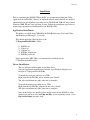
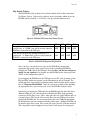
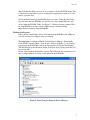
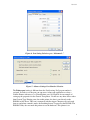
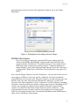
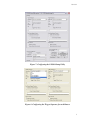
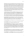
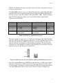
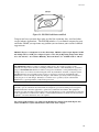
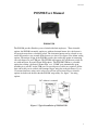
Ver 1.31
POS908 User Manual
POS908 USB
The POS908 provides Retailers peace of mind with their employees. Thru selectable
options, the POS908 can notify employees with an electronic buzzer if a cash drawer is
left open for more then a selectable period. The electronic buzzer can be selected to stay
on for 60 second or stay on until all the drawers are closed. See figure 5 for Alarm setting
options. The unique design of the POS908 provides the retailer the option of connecting
two cash drawers to one USB port. The POS908 will support all Cash Drawers wired for
use with an Epson, Star and Citizen POS printers. The POS908 USB has a selectable
option for creating a dedicated “Printer Port” or a “COM#” port automatically upon
installing it to your PC via the USB port. No special ports or cables are required. All the
data sent to this port is verified with a unique trigger string for each cash drawer. Up to
12 custom characters string can be selected or you can select from a Preset selection
options for both cash drawers thru the POS908 setup utility. See figure 7 for string
options.
DC Adapter is optional
Figure 1: Typical installation of POS908 USB
1
Ver 1.31
Installation
Prior to connecting the POS908 USB to the PC we recommend installing the Utility
application for the POS908. Drivers are included with the utility and they are installed
automatically on your Windows operating system. The POS908 USB will only work on
Windows 2000, XP and Vista operating systems. Follow the installation steps below to
insure proper operation and installation of your POS908 USB.
Application Installation:
The utility is available from CDROM in the POS908 Directory. Select the Utility
And Run the pos908setupV1_31.exe file.
This should install the following files to the
C:\Program Files\POS908 folder:
1)
2)
3)
4)
5)
POS908.exe
Usbser.sys
Usbprint.sys
POS908_usbprint.inf
POS908_usbser.inf
Other support files (MFC DLLs) are automatically installed into the
C:\Windows\System32 folder.
Driver Installation:
The user will need Admin rights to install the driver.
Once the application installation has finished, open Windows Explorer and
navigate to C:\Program Files\POS908.
To install the serial port emulator over USB:
Right-click the file POS908_usbser.inf and select “Install”.
The driver installation may take some time to complete.
To install the printer port emulator over USB:
Right-click the file POS908_usbprint.inf and select “Install”.
The driver installation may take some time to complete.
Once all the Drivers are installed select the dip switch on the POS908 to select
which driver will be used by the Plug and Play of your operating system. Go to
Dip Switch Setting for more detail.
2
Ver 1.31
Dip Switch Setting:
The POS908 had 4 dip switches located in the middle of the Cable connection.
See Figure 2 below. Only one dip switch is used to determine which device the
POS908 will be installed as. See Table 1 for dip switch definition below.
Figure2: POS908 USB Connection Panel Layout
Description:
This option will make the POS908 enumerate as a
serial device. A “COM#” port will be created when the
POS908 is connected to the USB port.
This option will make the POS908 enumerate as a
printer port. A “Printer Port” will be created when the
POS908 is connected to the USB port.
SW1
SW2
SW3
SW4
OFF
OFF
OFF
OFF
ON
OFF
OFF
OFF
Table1: POS908 USB Dip Switch Definition
Once you have selected the device type for the POS908 by selecting the
appropriate dip switch setting, you are now ready to install the POS908 by
plugging the USB cable to the USB port. Note that the Cash Drawer and power
supply are not required to be plugged into the POS908 for the setting up of the
drivers or the configuration process.
Upon plugging the POS908 into the USB port of your PC, your operating system
Plug and Play option may prompt you for information or driver locations. The
default directory created by the installation utility should contain all the required
files. C:\Program Files\POS908 Once the system has completed the installing
the appropriate files, you are now ready to test the POS908 using the utility.
Note that if you unplug the USB cable for the POS908 and plug the Cable into a
different USB port, you could be asked by the Plug and Play of the operating
system to redo the above steps. This is only done once for each USB port and it is
a normal process. The Driver will create the Ports for each USB ports you have
plugged the POS908 into. We recommend using the same USB port throughout
the installation to prevent confusion with the created ports. Multiple POS908 can
be installed onto your system. The system will create ports for each unit installed.
The setup utility can be configured to any of the Created ports for testing each
3
Ver 1.31
units individually. Each port created are assigned to the first POS908 found. This
is important to remember if you are setting up your application software to send
data to a specific Port.
We recommend setting up one POS908 device at a time. Using the same device
type for more then one POS908, you will need to setup a unique ID # for each
device using the POS908 Utility. See Figure 7. Failing to having a unique ID #
for each POS908, may cause a port conflict and may result in having
unpredictable responses from the POS908.
Setting up the ports:
Once you have installed the drivers and connected the POS908 to the USB port,
you will now need to configure your port settings.
The serial port is configures thru the Systems Device Manage,. Found in the
Control Panel. Open the Ports ( Com & Lpt) folder as in Figure 3, 4 & 5 and go
to properties of the POS908 Com # port. In properties, Select the Port Settings
Tab and then select the Advanced button. Select the desired Com port # and save
by pressing OK.
Do not worry about the Baud Rates settings. The USB port does not make use of
these settings and have no effect on the operation of the POS908.
Figure3: Serial Com port listing in Device Manager
4
Ver 1.31
Figure 4: Port Setting Selection go to “Advanced...”.
Figure 5: Advance Settings Port Number Selection.
The Printer port setting is different from the Serial setting. No Lpt port number is
assigned. In order to see the port you can access it thru your application or select a
Generic Printer with access to a Virtual Printer port. See Figure 6 for an example of
setting up the properties for the Generic Text printer. Do not use any other drivers other
then Generic Text. Printing your data to this printer, the data is sent directly to the
POS908 in ASCII text. This text is compared with the trigger Characters for each cash
drawers and when a match is made, the matching drawer is opened by the POS908. The
POS908 Utility does not need this printer to test the hardware. This printer is an
5
Ver 1.31
illustration only and can be used by older applications which do not see the Virtual
Printer Ports.
Figure 6: Virtual printer Port setting as Generic Printer.
POS908 Utility Software:
Now you are ready to connect the optional 24VDC power adaptor and cash
drawer to the POS908. The POS908 is equipped with a built in 24VDC pulse
generator ideal for Cash Drawers. The power connector is used for other devices
which may require a longer power pulse per trigger. Connect the hardware as
shown in Figure 1 above. Now Open the Utility software. First Select “The device
is plugged into:” Printer Port or Serial Port. Select the Port # for your option. See
Figure 7.
Now select the Trigger Characters for each Cash Drawer. You can select from a series of
preset triggers available or create your own for each drawer. We do not recommend
setting both drawers to the same value. The power adaptor is not able to trigger two Cash
Drawers at the same time. Select the pulse Duration for each trigger. A pulse of 0.5
Seconds is more then enough time to open a cash drawer. If you are triggering something
other then a cash drawer then you can select a longer trigger period to a maximum of 63.5
seconds. An external power adaptor will be required for any pulses longer then 0.5
seconds. Care should be taken on the amount of current used on each device. A long
trigger duration may cause the unit to over heat if too much current is drawn by the
device for an extended amount of time. Note that the Push Button on the POS908 has no
effect on any Cash Drawer Alarm options.
6
Ver 1.31
Figure 7: Configuring the POS908 Setup Utility
Figure 8: Configuring the Trigger Sequence for each Drawer
7
Ver 1.31
The POS908 cash drawer beeper function should only be used when the Cash drawer has
a drawer open sensor connected to the RJ12 wire. See Table 2 and Figure 9 for drawer
wiring requirements. Check with your cash drawer supplier to see if your drawer supports
drawer open sensor. The RJ12 Jacks for the Cash drawers on the POS908 are wired to
support cash drawers wired to work on Epson, Citizen and Star Printers. By selecting the
Enable Cash Drawer beeper check box, you will now be able to change the duration of
time for the drawer to be open before the electronic buzzer is sounded. Each cash drawer
can have its own custom duration of time. The electronic buzzer will stay on until the
cash drawer is closed. If you select check box for stop beeper after one minute, The
electronic buzzer will turn off after one minute if the drawer is not closed. If you trigger
a cash drawer while a drawer is left open, the electronic buzzer will repeat its cycle for
one minute and then turn off again.
An Alarm function is also available on the POS908. A cash drawer does not need to be
connected to the POS908 in order to use this function. The first option is Beep for 4
seconds. By sending a trigger to the POS908 for device 1 and having this option box
checked. A electronic buzzer will be sounded for a 4 second duration. If you have a
drawer attached to Device 1 then the drawer will open. The drawer open sensor has no
effect on this function. The Push button on the top of the POS908 will silence the beeper
if it is pressed before the end of the 4 second alarm duration. See Figure 10 Push Button.
The second option is Beep until Push Button is pressed. By sending a trigger to the
POS908 for device 2 and having this option box checked. An electronic buzzer will be
sounded until the push button is pressed. If you have a drawer attached to Device 2 then
the drawer will open. The drawer open sensor has no effect on this function.
The ‘Factory Default’ button will change all your screen settings back to factory default.
The ‘Save Setting’ button will save your screen settings to your hard drive. Next time
you start the utility the saved setting will be displayed on the screen.
The ‘Send Configuration’ button will copy the screen settings to your POS908. The
settings are sent to the selected device ‘The Device is plugged into:’ option. Once you
press the Send configuration button, the POS908 will now have the new settings saved
into its Flash memory. The POS908 will flash the LED and sound one long beep once the
data is saved to its flash memory. Note that the Configuration saved to your POS908 has
no relation to the device type. Serial or Printer port settings have no effect at all on the
saved settings. The flashed settings in the POS908 will always be the same regardless of
the port device type.
The ‘Get Configuration’ button is only supported when the POS908 is a Serial Device.
This will allow you to read the setup configuration from the flash memory of your POS
908. Select the proper Com port # before you press the Get Configuration button.
The ‘Send Trigger 1’ and ‘Send Trigger 2’ button is used for testing your POS908 with
the attached drawer(s). Pressing this button will send the drawer trigger string to the
8
Ver 1.31
POS908. The POS908 will trigger the selected drawer if the data string matches the data
saved in its flash memory.
The ‘Device ID#’ button is used to set a unique ID number for your POS908. This ID # is
required for the drivers to install properly if you are using more then one POS908 with
the same port type on the same computer. The default ID# is ‘0001’. Failing to having a
unique ID # for each device, It may cause a port conflict and have unpredictable
responses from the POS908.
Pin Number
1
2
3
4
5
6
Drawer # 1 Signal Name
Frame Ground
Drawer # 1 Sink Signal
+ 24 VDC
+ 24 VDC
Drawer # 1 Sink Signal
Drawer # 1, Open Drawer
Status Switch
Drawer # 2 Signal Name
Frame Ground
Drawer # 2 Sink Signal
+ 24 VDC
+ 24 VDC
Drawer # 2 Sink Signal
Drawer # 2, Open Drawer
Status Switch
Direction
Ground
Input
Power
Power
Input
Input
Table 2: RJ12 Drawer 1 and Drawer 2 pin out
The drawer solenoid is connected to + 24 VDC and to the Drawer Sink Signal Typically
pins 2 & 4. The Drawer Status Switch is connected to + 24 VDC and the switch is closed
only when the cash drawer is OPEN, typically pins 3 & 6. Special Note: If your cash
drawer is wired as a second drawer from your drawer manufacture. Say the solenoid is
Using Pin 4 & 5. The POS908 is designed to support both types of cash drawers and will
function properly in either Drawer # 1 or Drawer # 2.
Figure 9: RJ12 Connector Pin out for Drawer Cable and POS908 Connector 1& 2
Note: The electronic Buzzer in the POS908 is powered by the + 24 VDC power adaptor.
If the power adaptor is not connected, you will not hear any sound nor be able to open
any cash drawers. The Status Led will be on when the USB cable is connected to the PC.
A flashing LED indicates that an event is active ( Drawer is Open or Timing Loop).
9
Ver 1.31
Figure 10: POS908 Push Button and Led
Compact and easy to mount, these units are ideal for restaurants, bars, retail and other
service industry applications. The POS908 includes a 1-year limited warranty for parts
and Labor. Should you experience any problem you can contact your resellers technical
support team.
POS908 USB power consumption is less then 150 mAmps. POS908 weight 130 gm. Optional 24 DC
800 mAmps 120 Vac 60 HZ power adaptor Negative center. 500 gm, Operating Temperature Range
0C to 70C with 10% - 90% Relative Humidity, Electronic Buzzer 3.5 – 4.5 KHZ 90 db @ 1 Meter
Disclaimer
The Manufacture makes no claims or warranties with respect to the content or accuracy of this
publication or the product is describes, including warranties of fitness or merchantability for a particular
purpose. The Manufacture shall not be liable for any special, incidental or consequential damages, nor
damages due to use or misuse born from integration into any mechanical, electrical or computer system.
The Manufacture is not responsible for the accuracy of any device connected to the POS908. The
Manufacture reserves the right to make any changes to this manual or product(s) without obligation to
notify any person of such changes. Warranty is void if the case is opened by anyone other then the
Manufacture’s repair department or authorized repair center.
Note: This equipment has been tested and found to comply with the limit for a class A digital device,
pursuant to part 15 of the FCC rule. These limits are designed to provide reasonable protection against
harmful interference when the equipment is operated in a commercial environment. This equipment
generates uses and can radiate radio frequency energy and interference to radio communications. Operation
of this equipment in a residential area is likely to cause harmful interference in which case the user will be
required to correct the interference at its own expense.
The content of this manual is copy righted to the Manufacture and the Trade marks Epson, Star,
Citizen and IBM are registered trade marks of their trade name company.
10