1
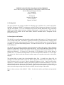
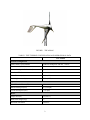
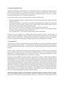
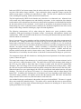
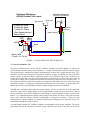
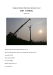
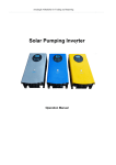
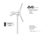
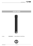
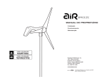
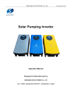
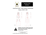
October 1999
•
NREL/CP-500-27062
Certification Testing for
Small Wind Turbines
D. Corbus, H. Link, S. Butterfield, C. Stork,
and C. Newcomb
National Renewable Energy Laboratory
T. Sasseen
Southwest Windpower
Presented at Windpower ‘99
Burlington, Vermont
June 20–23, 1999
National Renewable Energy Laboratory
1617 Cole Boulevard
Golden, Colorado 80401-3393
NREL is a U.S. Department of Energy Laboratory
Operated by Midwest Research Institute • Battelle • Bechtel
Contract No. DE-AC36-98-GO10337
NOTICE
This report was prepared as an account of work sponsored by an agency of the United States
government. Neither the United States government nor any agency thereof, nor any of their employees,
makes any warranty, express or implied, or assumes any legal liability or responsibility for the accuracy,
completeness, or usefulness of any information, apparatus, product, or process disclosed, or represents
that its use would not infringe privately owned rights. Reference herein to any specific commercial
product, process, or service by trade name, trademark, manufacturer, or otherwise does not necessarily
constitute or imply its endorsement, recommendation, or favoring by the United States government or any
agency thereof. The views and opinions of authors expressed herein do not necessarily state or reflect
those of the United States government or any agency thereof.
Available to DOE and DOE contractors from:
Office of Scientific and Technical Information (OSTI)
P.O. Box 62
Oak Ridge, TN 37831
Prices available by calling 423-576-8401
Available to the public from:
National Technical Information Service (NTIS)
U.S. Department of Commerce
5285 Port Royal Road
Springfield, VA 22161
703-605-6000 or 800-553-6847
or
DOE Information Bridge
http://www.doe.gov/bridge/home.html
Printed on paper containing at least 50% wastepaper, including 20% postconsumer waste
CERTIFICATION TESTING FOR SMALL WIND TURBINES
Dave Corbus, Hal Link, Sandy Butterfield, Christof Stork, Charles Newcomb
National Renewable Energy Laboratory
1617 Cole Blvd.
Golden, CO 80401
Tim Sasseen
Southwest Windpower
2131 N. First St.
Flagstaff, AZ 86003
1.0 Background
This paper describes the testing procedures for obtaining type certification for a small wind turbine.
Southwest Windpower (SWWP) is seeking type certification from Underwriters Laboratory (UL) for the
AIR 403 wind turbine. UL is the certification body and the National Renewable Energy Laboratory
(NREL) is providing technical assistance including conducting the certification testing. This is the first
small turbine to be certified in the United States, therefore standards must be interpreted and test
procedures developed.
2.0 Description of the Turbine
The AIR 403 is a small battery-charging turbine rated to produce 400 watts in a 12.5 meters per second
(m/s) (28 mph) wind speed. The turbine is generally used either as a stand-alone battery charging system
or in conjunction with a small photovoltaic (PV) array as a wind-PV hybrid system to power loads such
as lighting, TV, and small household appliances. The AIR 403 turbine is also very popular on sailboats
for on-board power.
The AIR 403 uses a brushless permanent magnet alternator to produce three-phase variable alternating
current (AC) output that is then rectified to direct current (DC). The rectifier and charge controller for the
turbine are housed in the nacelle of the turbine and are directly heat-sinked to the turbine body. The
turbine rotor diameter is 1.15 meters (4 ft), the weight is 5.85 kilograms (13 lb), and the turbine is
available in 12-, 24-, and 48-volt configurations. The cut-in wind speed of the turbine is 2.7 m/s (6 mph).
The turbine has a brake switch that shorts the turbine output wires together and results in the turbine
stopping.
The turbine blades are made from injected-molded carbon fiber. In winds above about 18.8 m/s
(42 mph), the carbon-fiber blades will go into flutter to protect the turbine from overspeeding. This is
called aeroelastic stall in the user’s manual (Southwest Windpower 1999). During normal turbine
operation (i.e., turbine connected to batteries), the turbine regulator will brake the turbine to a very slow
rotational speed when the batteries are fully charged. During open-circuit operation of the turbine (i.e.,
turbine disconnected from the batteries), the turbine regulator will brake the turbine to prevent overspeed
and to prevent the output voltage from rising above double the rated voltage of the turbine.
Figure 1 shows a picture of the AIR 403. Table 1 lists the basic turbine specifications and operational
data.
1
FIGURE 1. THE AIR 403
TABLE 1. TEST TURBINE CONFIGURATION AND OPERATIONAL DATA
Test Turbine
General Configuration
Make, Model, Serial Number
Southwest Windpower AIR 403, #19825
Rotation Axis (H / V)
H
Orientation (upwind / downwind)
Upwind
Number of Blades
3
Rotor Diameter (m)
1.15 m (4 ft)
Hub Height as tested (m)
13.7 m (45 ft)
Operation
Rated Electrical Power (W)
400
Rated Wind Speed (m/s)
12.5 (28 mph)
Cut-in Wind Speed (m/s)
2.7 (6 mph)
Rotor
Swept Area (m2)
1.8 (19.4 ft2)
Blade Pitch Angle (deg)
2.5
Direction of Rotation
Clockwise
2
Tower
Type
Tubular (schedule 40 pipe) guyed tilt-up
Height
13.7 m (40 ft ) with 1.5 m (5 ft) adapter
Control and Electrical System
Controller: Make, Type
Autobrake, rectifier/charge controller
Electrical Output Voltage
Nominal 12 volts (24- and 48-volt versions available)
3.0 Certification Testing Overview
Figure 2 shows an overview of the requirements for small wind turbine type certification. Specific tests
are required under “type testing.” Optional but desirable tests are shown under “type characteristics
measurements.” However, the blade tests and load measurements required under type testing for large
turbines can be waived in lieu of a “duration test” per IEC 61400-22 Annex E. Also required under type
testing is a safety and function test. SWWP chose to certify a power curve for their turbine, therefore a
power performance test is being conducted according to the requirements of IEC 61400-12. The safety
and function, duration, and power performance tests are the three main tests required for the certification
of the AIR 403. NREL has written a detailed test plan for each test being conducted that describes the
testing approach, configuration, and procedures. NREL is also obtaining some additional data on the
SWWP turbine’s characteristics in order to provide inputs to the design evaluation process.
Design
Evaluation
Type
Testing
Safety and
Function Test
Duration Test
Manufacturing
Evaluation
Final
Evaluation
Report
Foundation
Design
Evaluation
Type
Characteristic
Measurement
Power Performance Test
Type
Certificate
FIGURE 2. TESTS REQUIRED FOR SMALL WIND TURBINE CERTIFICATION
3
3.1 Safety and Function Test
The purpose of the safety and function test is to verify that the turbine has adequate provisions to operate
safely under all conditions. It is conducted in accordance with provisions listed in IEC 61400-22 Annex
D. For larger turbines, this testing focuses on the control system for the turbine. However, the control
systems for small turbines are very simple and often passive.
For the AIR 403 turbine, the safety and function test consists of the following:
Emergency shutdown operation. Conduct a brake test to ensure the turbine stops in high winds when
the brake is applied.
Power and speed control. Verify that the aero-elastic stall mechanism of the blades limits speed and
power and verify that the charge controller limits current in high winds when the battery voltage is
greater or equal to the charge controller voltage set-point.
Yaw control. Visual inspection, if problems are noted a test plan will be developed.
Grid loss behavior. Open circuit test includes 4 Hz sampling of current to verify internal braking
mechanism of turbine controller reduces current to zero.
Over-speed protection. Verify blade "aeroelastic stall" reduces current output.
The above tests are contained in a checklist and capture the intent of the IEC 61400-2 Annex D
requirements without making the testing so burdensome and expensive that small turbine manufacturers
would be unable to afford the it. For example, visual inspection of adequate yaw control is relatively
inexpensive compared to instrumenting, recording, and analyzing yaw and wind direction signals.
3.2 Duration Test
As mentioned previously, the duration test may replace the blade tests and load measurements required
under type testing for small turbines. This variance from the large turbine standard can help reduce the
cost of testing small turbines because it is usually easier to conduct a duration test as opposed to blade and
load tests.
The IEC 61400-2 Annex E requires that the turbine undergo testing for 1,500 hours of power generation
and six months test duration, as well as operation in winds greater than 10 m/s (22 mph) for 250 hours
and operation in winds greater than 15 m/s (33 mph) for 25 hours. The operating requirements per IEC
61400-2 Annex E are that the turbine achieve at least 90% availability.
In addition to the availability requirement, NREL requires that the turbine’s monthly energy production
throughout the test be no less than 20% of the first month’s energy production after correction for wind
resource differences. A 20% change in the monthly energy production would indicate a problem with yaw
bearings, blades, bearings, generator, or the rectifier. To compare energy production, both the expected
energy production and measured energy production are determined. Expected energy production is the
energy that would have been produced under the measured wind conditions if the turbine operated on its
power curve as measured during the first month. Measured energy production is energy that the turbine
actually produced as measured by the power transducer. The comparison uses data obtained when turbine
and anemometer are clear of wakes from any obstacles and when the winds are within the range of the
power curve measured during the first month of duration testing.
Another requirement by NREL for the duration test is that the turbine maintains its ability to reduce
power output when the batteries are fully charged. NREL has developed a procedure to test the charge
controller to verify that it operates during the entire duration test. The turbine is connected to the battery
4
bank near full SOC and current output from the turbine observed as the battery approaches the voltage
set-point of the turbine charge controller. Upon reaching the charge controller voltage set-point, the
turbine current output is verified to be reduced below 3 amps. This test will be conducted at least three
times, including the beginning, middle, and end of the duration test.
The final requirement by NREL for the duration test is that there is no abnormal wear. Abnormal wear
will be noted in the final component wear and durability assessment. At the completion of the duration
test the turbine will be taken down from the tower and a detailed component wear and durability checklist
for the entire turbine will be conducted. It will include an assessment of the physical integrity of the
blades noting any cracks or abnormal surface conditions, the mechanical alignment of the rotor, and an
analysis of the charge controller including any signs of thermal degradation.
The following measurements will be taken during the duration test: power production, turbine
availability, wind speed consisting of 10-minute average, 3-second gust, and turbulence intensity and
wind direction. NREL has included wind direction to avoid using data obtained when upwind obstacles
affect the turbine or anemometer.
Power is measured by a power transducer and also calculated from current and voltage measurements for
the duration test. Voltage measurements are taken at the top of the wind turbine tower and also at the
battery bank, so that the line losses can be calculated. The AIR 403 is available in a 12-, 24-, and 48-volt
version; the 12-volt version was selected for the duration test because it produces the highest current, and,
therefore, the highest thermal loading. Turbine availability is determined from the test log and
supplemented by a manual switch connected to the data acquisition system. If NREL staff note any
problems with the turbine the switch is thrown and an entry is made in the log. This method avoids the
undesirable loss of availability when the turbine is shut down for instrumentation changes or special tests.
The arrangement for the AIR 403 duration test, including the measured parameters for the data acquisition
system, is shown in Figure 3.
The battery bank voltage in the duration test is varied by means of applying a constant resistance load in
series with a low- voltage disconnect (LVD). The load will be used to lower the battery bank voltage to
the LVD set point (equal to about 40% state of charge) at which point the load will automatically
disconnect. The reset voltage of the LVD will correspond to full battery state-of charge (SOC). Hence
the LVD will keep the load disconnected until the turbine recharges the batteries back to the 100% SOC.
When the batteries are once again charged, the LVD will reconnect the load and the batteries will again
discharge. The load will vary about 15% because it is a fixed resistance and the voltage changes with
battery SOC. In addition, the discharge rate of the batteries will vary depending on the turbine output.
The turbine charge controller will regulate current when the batteries reach 100% SOC and hence the
charge controller will be tested every time the batteries reach 100% SOC.
Also included in the type certification for the turbine is the tower for the AIR 403. The tower is a guyed,
tilt-up tower made from schedule 40 pipe. The turbine will be tested with this tower to ensure that the
tower is designed for all the loads encountered during the duration test including the 25 hours of wind
speeds greater than 15 m/s (33 mph).
5
Southwest Windpower
AIR 403 Wind Module
Southwest Windpower
AIR 403 Duration Test Layout
Wind Vane
Wind speed
Turbine DC Volts
Turbine DC Amps
Turbine DC Power
Wind Speed/direction
Brake Status
LVD
Lightning
Arrestor
Voltage taps
DAS:
300W
Brake
Battery Bank
(Trojan L-16, 700 Ah)
FIGURE 3. AIR 403 DURATION TEST SCHEMATIC
3.3 Power Performance Test
The power performance test follows the IEC 61400-12 standard except that changes are required to
account for the effect that battery state-of-charge (i.e., voltage variation in the load) has on power output.
The electrical load is controlled at voltages corresponding to a battery SOC of approximately 40%, 70%,
and 100%, and 60 hours of operation is required for each SOC voltage. In addition, for each of the three
voltage settings, 30 minutes of data is required for each 0.5 m/s (1 mph) wind speed bin. Because this is
the first power performance test for a small wind turbine certification, the variation of the power curve as
a function of voltage will be evaluated to determine the sensitivity of the power curve to battery SOC. If
the voltage variation has a small effect on the power output, then the final power curve will be an average
of the three voltages. If voltage has a significant effect on the power curve output (e.g., greater than 5%),
then the power curves corresponding to the three voltage settings may be shown separately.
The AIR 403 is available in three different nominal voltages: 12-, 24-, and 48-volts. It is anticipated that
the power output will be slightly higher as the nominal turbine voltage increases, hence three separate
power performance tests will be conducted corresponding to the three nominal voltage versions of the
turbine. It is anticipated that the nominal voltage rating of the turbine will have a larger impact on the
power curve than the voltage variation corresponding to battery-state-of-charge. Hence the data
requirements for voltage variations as a function of battery state-of-charge may be relaxed for tests of 24volt and 48-volt AIR 403 turbine versions.
A second change from the IEC 61400-12 standard is accommodation of the charge controller. The power
performance test will be conducted so that the charge controller does not have any effect on the power
6
output. This will be done by setting the charge controller voltage above that of the load so that the charge
controller never regulates current. Voltage control of the load will be maintained using Alternative
Engineering’s Enermaxer load controller configured to maintain voltage within 2% of the desired setting.
The Enermaxer load controller uses pulse-width modulation to control current to a dump load and thereby
maintain voltage control.
Per IEC 61400-12, the anemometer must be located between 2 and 4 rotor diameters from the turbine. In
this test the anemometer will be mounted 2.5 rotor diameters from the turbine. Another anemometer is
located approximately 15 m (50 feet) from the turbine tower as a check on the primary anemometer. An
assessment will be made to determine if there are any significant anemometer wake effects on the turbine
from the primary anemometer. Figure 4 shows the layout for the power performance test.
Turbine Tower Anemometer
AIR403
8
7
6
5
4
3
2
1H
H
H
H
H
1
H
H
L
L
L
PU
L
6
RO
NT 4 5
CO 3
L
CIT
EX
H
L
L
L
L
N
IO
AT 4
O
CA 2
1
TS
PU 4
E IN 3
LS
1
Wind Speed
Wind Direction
Barometric Pressure
Temperature
Wetness Sensor
+12
2
2
1
3
2
DAS
Power Transducer
Load (14000W)
Current Sensor
Batt
Load
Batt
Load
+
+
-
Voltage Sensing
Enermaxer Load Control
Batteries
FIGURE 4. TURBINE CONFIGURATION FOR POWER PERFORMANCE TEST
3.4 Verification of Design Assumptions
The three main certification tests for small turbines shown in Figure 2 fall under “type testing” and “type
characteristic measurements.” However, the “design evaluation” process according to IEC 61400-2 is
based on assumptions and/or measurements of the following parameters: rated and maximum rotor speed
and power, and maximum yaw rate. As part of the duration and/or power performance test, these
parameters will be measured. The maximum and rated rpm can be calculated by measuring the frequency
of the AC ripple downstream of the rectifier on the DC bus and calculating wind turbine rpm based on
frequency and the number of poles in the generator. The maximum yaw rate will be estimated by using a
video camera at slow speed to measure yaw in degrees for a given time interval. Simplifying the yaw rate
7
measurement by using a video camera, as opposed to instrumenting the turbine with an expensive yaw
sensor set-up, helps to reduce the complexity and costs for small certification testing.
4.0 Future Work in Small Wind Turbine Certification Testing
Small wind turbine certification testing is just starting, with the AIR 403 certification test being the first
certification test in the United States. Work is now beginning on a revision of IEC 61400-22. Lessons
learned from the current certification testing will be incorporated in the IEC 61400-22 revision and into
future certification testing protocols. NREL will continue to develop small wind turbine testing
capabilities and to share information.
References
Standard IEC 61400-22, International Electrotechnical Commission (IEC), Draft Wind Turbine Generator
Systems Part 22: Wind Turbine, 88/102/CD, 18 Dec. 1998.
Standard IEC 61400-2, International Electrotechnical Commission (IEC), Wind Turbine Generator
Systems Part 2: Wind Turbine, 18 Dec. 1996-04.
Standard IEC 61400-22, International Electrotechnical Commission (IEC), Wind Turbine Generator
Systems Part 12 – Wind Turbines Power Performance Testing: Wind Turbine, 88/66/CDV, 1997-10-03.
AIR 403 Owner’s Manual, Southwest Windpower, Flagstaff AZ, 1999.
8