1
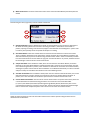
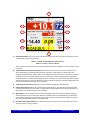
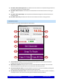
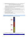
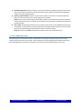
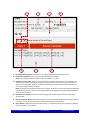
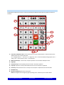
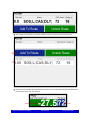
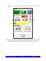
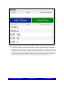
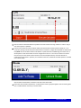
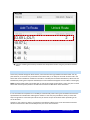
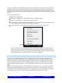
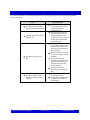
NOVEMBER, 2015 TSD RALLY RUNNERTM USER MANUAL 3 PEAK ENGINEERING CONTENTS 1 What Is TSD Rallying? .................................................................................................................................................3 1.1 Overview .........................................................................................................................................................3 1.2 Tools Used .......................................................................................................................................................3 2 What is The TSD Rally Runner? ...................................................................................................................................4 3 Tour Of The User Interface .........................................................................................................................................5 3.1 Menu Bar.........................................................................................................................................................5 3.2 GPS Panel ........................................................................................................................................................5 3.3 Clocks Panel ....................................................................................................................................................6 3.4 Deviation / Scratchpad Panel ..........................................................................................................................7 3.5 Route Control Panel ........................................................................................................................................9 3.6 HUD Panel .......................................................................................................................................................9 3.7 Odometer Panel ............................................................................................................................................11 3.8 Workplace Panel Selector Buttons ................................................................................................................12 3.9 Workplace Panels ..........................................................................................................................................13 3.9.1 Route Workplace Panel .....................................................................................................................13 3.9.2 Calc Workplace Panel ........................................................................................................................14 3.9.3 Graph Workplace Panel .....................................................................................................................16 3.10 Keypad.........................................................................................................................................................17 4 Operational Walkthrough .........................................................................................................................................19 4.1 Starting The System ......................................................................................................................................19 4.2 ‘In-Program’ Set-Up ......................................................................................................................................19 4.3 Rally Start ......................................................................................................................................................20 4.4 Proceeding Along ..........................................................................................................................................21 4.5 Using The Built-In Calculator .........................................................................................................................23 4.6 Correcting / Modifying The Route Table .......................................................................................................27 4.7 Recovering From Wrong Turns & Detours ....................................................................................................27 4.8 Control Stops .................................................................................................................................................28 4.9 End-Of-Section ..............................................................................................................................................29 4.10 Operating In Class B Mode ..........................................................................................................................29 5 Set-Up & Configuration ............................................................................................................................................30 5.1 Software Installation .....................................................................................................................................30 5.1.1 Archive Extraction .............................................................................................................................30 5.1.2 MCR Installation ................................................................................................................................30 TSD RALLY RUNNER USER MANUAL PAGE 1 OF 43 3 PEAK ENGINEERING 5.1.3 Keypad Installation ............................................................................................................................30 5.2 GPS Installation .............................................................................................................................................30 5.3 TSD Rally Runner Configuration ....................................................................................................................31 5.3.1 ‘License’ Subsection...........................................................................................................................32 5.3.2 ‘Env’ Subsection .................................................................................................................................32 5.3.3 ‘Comm’ Subsection ............................................................................................................................32 5.3.4 ‘Target_Dev’ Subsection ....................................................................................................................32 5.3.5 ‘Calc’ Subsection ................................................................................................................................33 5.3.6 ‘Misc’ Subsection ...............................................................................................................................33 6 Licensing ...................................................................................................................................................................35 7 External Components ...............................................................................................................................................36 7.1 Tablets ...........................................................................................................................................................36 7.2 GPS Units .......................................................................................................................................................36 8 Troubleshooting........................................................................................................................................................37 9 Disclaimer .................................................................................................................................................................38 10 Contact....................................................................................................................................................................39 Appendix A: Sample Rally Instructions ........................................................................................................................40 A.1 Route Section Notes .....................................................................................................................................40 A.2 End Of Section Descriptions ..........................................................................................................................41 A.3 Speeds And Timing........................................................................................................................................42 TSD RALLY RUNNER USER MANUAL PAGE 2 OF 43 3 PEAK ENGINEERING 1 WHAT IS TSD RALLYING? 1.1 OVERVIEW A TSD Rally (time-speed-distance or regularity / navigational rally) is a form of motorsport rally where competitors are given a set of navigational instructions and are asked to follow them in making their way through a very specific Route over a very specific amount of time. The Route is composed of a number of Sections (or Stages) and they in turn are composed of various segments – each of which is to be driven at a particular average speed. The goal for competitors is to make their way through the given Route while always staying on-course and on-time. Their progress over the rally is scored at Control Stops along the way where rally officials compare the individual competitors’ time-of-arrival vs a theoretical ‘ideal’ time-of-arrival for that particular location (i.e. the time at which competitors should have arrived had they followed the given instructions perfectly – also known as Zero Time). The difference between the two is the Ideal Time Deviation and it is used to assign Penalty Points. Ultimately, the team with the lowest number of Penalty Points is declared the winner. 1.2 TOOLS USED There is plenty of diversity in the exact rules and regulations used amongst the many TSD Rallies held around the world. However, in general, they are all based on the concept outlined above – that is, deciphering instructions, staying on-course and staying on-time. From the competitors’ point of view, this can be accomplished using various tools as aids – each with their own degree of associated overall complexity and effectiveness. In the most basic approach, the only tool that is required is a working vehicle odometer. One step above that is the addition of a timer and some form of calculator to aid in the manual calculations required to keep track of progress. However, in practice, these sort of basic approaches quickly get totally out of hand if the competitor is aiming for even moderate levels of accuracy (let alone anything approaching Zero Time and thus Zero Penalty Points). The main challenge for a competitor is to be able to process all of the relevant information quickly and accurately while dealing with potential unexpected issues along the rally. Over time, various electronic (computer) systems have been developed to further aid with this processing. They of course differ in what they can ultimately perform, their ease-of-use, their flexibly and last but certainly not least – their cost. In general though, they all fall under 1 of 2 categories: 1) Class A Rally Computers: Computers intended for Class A TSD Rallies. Such rallies allow for an unlimited amount of electronic assistance and consequently these computers usually aim to provide the competitor with a real-time indication of what their Ideal Time Deviation always is. 2) Class B Rally Computers: Computers intended for Class B TSD Rallies. Such rallies generally do not allow for a computer to fully take over and perform all of the calculations determining the competitor’s Ideal Time Deviation. As a result, these computers usually only incorporate configurable odometers / timers which at least simplify some of the main procedures / calculations, particularly when it comes to, for example, recovering from unexpected wrong turns or mistakes along the Route. TSD RALLY RUNNER USER MANUAL PAGE 3 OF 43 3 PEAK ENGINEERING 2 WHAT IS THE TSD RALLY RUNNER? The TSD Rally Runner is a highly specialized piece of software that can turn any Windows based machine into an extremely powerful TSD Rally computer. It is specifically designed as the core of a System that allows a TSD Rally competitor (the User) to excel in competition and gain an upper hand over all other rivals. The program can be configured to operate as either a Class A or Class B TSD Rally computer depending on what type of event the User is competing in. It makes use of an external GPS device for highly accurate distance and time measurements, which the User can control. It provides powerful data entry / management / presentation as well as calculation features in order to allow the User to get things done quickly and accurately in the heat of competition. In Class A form, it can also ultimately compute Ideal Time Deviation in real-time all along the Route. In the following sections of this document, the various features of the TSD Rally Runner and how it can be used in competition are explained in detail. TSD RALLY RUNNER USER MANUAL PAGE 4 OF 43 3 PEAK ENGINEERING 3 TOUR OF THE USER INTERFACE The TSD Rally Runner user interface (Main UI) is composed of a number of ‘panels’ as shown below (diagram numbers correspond to document sections providing further detailed explanations): 3.6 3.4 3.3 3.1 3.2 3.5 3.7 3.9 3.8 3.10 The functions of these panels and of everything inside them is described in the sections that follow. 3.1 MENU BAR 1 2 3 1) License Button: Opens a dialog box displaying license information (see the Licensing section for more details). 2) Help Button: Opens a dialog box describing the available ‘help’ sources. 3) About Button: Opens a dialog box displaying program version / configuration information. 3.2 GPS PANEL Panel housing all of the controls related to establishing a GPS connection. TSD RALLY RUNNER USER MANUAL PAGE 5 OF 43 3 PEAK ENGINEERING 3 1 2 4 6 5 7 1) Connect Button: Attempts to connect to the GPS using the specified COM Port. 2) Disconnect Button: Disconnects from the GPS. 3) GPS Data (‘Spinner’) Indicator: ‘Spins’ to show new GPS data arriving once a connection has been established. 4) Incoming GPS Data COM Port Selector: Used to select the COM Port through which the incoming GPS data is to be received. 5) GPS Out Checkbox: Used to enable / disable forwarding of GPS data to an extra COM Port. 6) Outgoing GPS Data COM Port Selector: If the GPS out Checkbox is ticked, this combo-box selects the COM Port to which outgoing GPS data is to be forwarded. Forwarding GPS data allows for the GPS device to be accessible to other 3rd party programs such as, for example, Microsoft Streets & Trips* for further mapping / location / navigation purposes. *Not included as part of the TSD Rally Runner software package. 7) GPS / Data Processing Status: Under normal operating conditions, once a connection has been established, this text box displays real-time information related to the incoming GPS signal. In cases where errors are encountered either with the GPS signal or during internal data processing, a brief description of these errors is shown in this text box for reference. 3.3 CLOCKS PANEL Panel housing all of the controls related to time-keeping. TSD RALLY RUNNER USER MANUAL PAGE 6 OF 43 3 PEAK ENGINEERING 1 2 3 4 1) Wall-Clock Time: Displays the current local Wall Clock Time derived from the GPS signal and the Userconfigured Clock Offsets. NOTE: The User needs to specify a Time Zone Offset in the Configuration File (see the Set-Up & Configuration section for more details) in order for the Wall Clock to correspond to the User’s current local time. 2) ‘Fine-Tune’ Clock Offset Control: Used to ‘fine-tune’ the Clock Offset (in 1s intervals). The Clock Offset is defined as the difference between the exact time of day provided through the GPS signal (UTC) and the User’s current local time. This control allows for ‘fine-tuning’ in order to exactly match the Official Rally Time. 3) Section Timer Control: Displays the current value of and controls (resets / starts / holds) the Section Timer. The Section Timer is intended to measure the amount of time elapsed since the start of the current Route Section (or Stage) and it can be configured to display that time in ‘hh:mm:ss’ format or just plain seconds (see the Set-Up & Configuration section for more details). 4) Miscellaneous Timer Control: Displays the current value of and controls (resets / starts / holds) the Miscellaneous Timer. The Miscellaneous Timer can be freely used to measure any elapsed time as needed and it can be configured to display that time in ‘hh:mm:ss’ format or just plain seconds (see the Set-Up & Configuration section for more details). 3.4 DEVIATION / SCRATCHPAD PANEL The Deviation Panel houses most of the controls related to Ideal Time Deviation. The system calculates Ideal Time Deviation (i.e. deviation from the ideal Zero Time) in real-time based on the User-specified Route, the current Section Odometer, the current Section Timer and 2 deviation ‘system factors’ (Dev F1 & Dev F2). The general governing equations are shown below: DEVCALC = f (Route, Section Odometer, Section Timer) DEVOVERALL = DEVCALC + Dev F1 + Dev F2 TSD RALLY RUNNER USER MANUAL PAGE 7 OF 43 3 PEAK ENGINEERING 1 2 3 4 1) ‘Fine-Tune’ Dev F1 Control: Used to ‘fine-tune’ the Dev F1 factor (in 1s intervals). In practice, Dev F1 can be used as a deviation ‘fudge-factor’ as needed by the User (see the Operational Walkthrough section for more details). 2) Dev F2: Displays the value of the Dev F2 factor. In practice, the System uses Dev F2 when keeping track of deviation across Route Section boundaries or Control Stops (see the Operational Walkthrough section for more details). 3) Null Dev Button: ‘Nulls’ (i.e. resets) the current deviation such that: DEVOVERALL = DEVCALC + Dev F1 + Dev F2 = Dev F1 This is done by setting Dev F2 as follows: Dev F2 = -1*DEVCALC In practice, nulling the deviation should be done at the Rally Start, when re-starting after Route Section breaks or when re-starting after Control Stops (see the Operational Walkthrough section for more details). 4) Save Dev Button: Saves the current calculated deviation DEVCALC to Dev F2. Dev F2 = DEVCALC In practice, saving the deviation should be done when moving from one Route Section to the next in conjunction with clearing the Route (see the Operational Walkthrough section for more details). When the TSD Rally Runner is operated in Class B Mode, the Deviation Panel is replaced with the Scratchpad Panel. This panel provides a place for the User to write in the results of their manual Ideal Time calculations and compare them to the Current State parameters in order to quickly gauge what the overall Ideal Time Deviation happens to be. 1 3 2 4 1) Calculated Section Odometer: Provides a place for the User to enter the odometer distance for a point at which Ideal Time is being calculated. 2) Calculated Section Ideal Time: Provides a place for the User to enter the calculated Ideal Time for the point corresponding to the odometer distance entered above. 3) Mark Section Odometer: The value of the Section Odometer at the instant the Mark Button (HUD Panel) was last clicked. TSD RALLY RUNNER USER MANUAL PAGE 8 OF 43 3 PEAK ENGINEERING 4) Mark Section Timer: The value of the Section Timer at the instant the Mark Button (HUD Panel) was last clicked. 3.5 ROUTE CONTROL PANEL Panel housing the main (‘high-level’) controls related to the Route. 1 2 3 4 5 1) Open Route Button: Opens a dialog box from which an existing Route File can be selected. Opening this file loads the existing Route from it as well as all timing parameters / information stored inside. In practice, opening an existing route would only happen in the aftermath of something like a ‘system crash’ in order to pick up exactly where the System left off prior to crashing. 2) Clear Route Button: Clears the entered Route and resets the Section Odometer as well as the Section Timer. In addition, depending on the states of the Snap Clr and Save Dev Clr checkboxes (see below), the Ideal Time Deviation just prior to the Route being cleared could be saved in order to seamlessly transition from one Route Section to the next while carrying over accurate calculations. In practice, the Route should be cleared right at the end of the current Route Section. 3) Snap Clr Checkbox: If this checkbox is ticked, when the User clicks the Clear Route Button, the Section Odometer is set to the Official Distance of the Route Point that is closest to the current location just prior to the Route being cleared. In practice, when the Route is cleared at the end of the current Route Section, selecting this options ensures that the Section Odometer is re-calibrated momentarily in order to calculate and pass a totally accurate Ideal Time Deviation over to the following section. 4) Save Dev Clr Checkbox: If this checkbox is ticked, when the User clicks the Clear Route button, the current Ideal Time Deviation is saved to the Dev F2 system factor just prior to actually clearing the Route. In practice, this is how the Ideal Time Deviation is passed on from one Route Section to the next. 5) Current Route Section Name: The name of the current Route Section. The System continuously writes the current Route data and associated timing parameters to a Route File in the Route Data folder (‘C:\Users\<User Name>\Documents\3 Peak Engineering\TSD Rally Runner\Route Data’) with a name corresponding to whatever is written in this text box. That file can later be opened and the data brought back in case of some unexpected system crash over the course of the current Route Section. 3.6 HUD PANEL Heads-up-display showing key real-time information related to the vehicle’s position along the Route and it’s deviation from the ideal time. TSD RALLY RUNNER USER MANUAL PAGE 9 OF 43 3 PEAK ENGINEERING 3 1 4 2 5 6 9 8 10 7 1) Ideal Time Deviation: The current (real-time) deviation from Zero Time. The governing equations used in calculating this value are shown below: DEVCALC = f (Route, Section Odometer, Section Timer) DEVOVERALL = DEVCALC + Dev F1 + Dev F2 These calculations are performed every time new GPS data becomes available (i.e. about once per second by default). 2) Target Ideal Time Deviation Format Selector: Used to select the type of format for the System to use when calculating the Target Ideal Time Deviation. In general, in TSD rallying, the Target Ideal Time Deviation should always be ‘0’ but in rallies where Time-Allowances can be used, it could be the case that a different deviation should be targeted in order to minimize the amount of Penalty Points collected if unexpected delays / troubles come up along the route. The System can automatically calculate the Target Ideal Time Deviation for such cases based on the Current State and the User’s relevant configurations (see the Set-Up & Configuration section for more details). 3) Target Ideal Time Deviation: Displays the current calculated Target Ideal Time Deviation. 4) Vehicle Target Speed: Displays the current Vehicle Target Speed (i.e. the speed that the vehicle should currently be travelling at). This number is a function of the entered Route and the Section Odometer (i.e. the location of the vehicle along the entered Route). 5) Mark Button: Takes a ‘snapshot’ of the Current State (displays the various Timers, Odometers and the Ideal Time Deviation at the moment the button was clicked). When the TSD Rally Runner is operated in Class B Mode, this button also writes the current values of the Section Odometer and Section Timer into their corresponding fields inside the Scratchpad Panel. 6) Next Route Point Official Distance: The distance from the start of the current Route Section to the next Route Point that is coming up ahead. TSD RALLY RUNNER USER MANUAL PAGE 10 OF 43 3 PEAK ENGINEERING 7) Next Route Point Remaining Distance: The distance from the vehicle’s current position along the Route to the next Route Point that is coming up ahead. 8) Next Route Point Instruction: The instruction to be followed at the next Route Point that is coming up ahead. 9) Next Route Point Speed Change: The new speed to be followed starting at the next Route Point that is coming up ahead. 10) Next Route Point Delay: The delay to be taken at the next Route Point that is coming up ahead. 3.7 ODOMETER PANEL Panel housing all of the controls related to distance measurement. 1 2 3 4 5 6 7 8 9 1) Section Odometer: Displays the current value of the Section Odometer. This should be the distance travelled since the start of the current Route Section. 2) Miscellaneous Odometer: Displays the current value of the Miscellaneous Odometer. This can be the distance travelled from any point up to the current location as chosen by the User. 3) New Section Odometer Value: The Section Odometer can be set to any value as needed by entering that value in this text box and clicking the Set Odometer Button (see below). 4) New Miscellaneous Odometer Value: The Miscellaneous Odometer can be set to any value as needed by entering that value in this text box and clicking the Set Odometer Button (see below). TSD RALLY RUNNER USER MANUAL PAGE 11 OF 43 3 PEAK ENGINEERING 5) Odometer Factor / New Odometer Factor Value: Displays the current value of the Odometer Factor and allows for a new Odometer Factor to be entered into the System. The Odometer Factor is defined as: Odometer Factor = Official Rally Distance / Raw GPS Distance Both odometers (described above) use this Odometer Factor in order to translate the raw GPS distance measurements into distances that match those specified in the Official Rally Notes. In order to enter a new Odometer Factor into the System, the new value should be written into this text box and then the User should click the Set Odometer button (see below). 6) Set Odometer Button: Sets both odometers to the new values specified (if any are entered) and updates the System with the new Odometer Factor value (if a new value has been entered). 7) Snap To Route Button: Sets the Section Odometer to the Official Distance of the Route Point that is closest to the current location. In practice, this is useful in quickly re-calibrating a ‘drifting’ odometer while passing through a known Route Point. 8) Copy Section Odometer Button: Copies the current value of the Section Odometer onto the computer’s clipboard (to be pasted later on as needed). 9) Copy Miscellaneous Odometer Button: Copies the current value of the Miscellaneous Odometer onto the computer’s clipboard (to be pasted later on as needed). 3.8 WORKPLACE PANEL SELECTOR BUTTONS Set of buttons that control which Workplace Panel (see below) should be currently visible. 1 2 3 1) Route Workplace Panel Button: Makes the Route Workplace Panel (see below) currently visible. TSD RALLY RUNNER USER MANUAL PAGE 12 OF 43 3 PEAK ENGINEERING 2) Calc Workplace Panel Button: Makes the Calc Workplace Panel (see below) currently visible. 3) Graph Workplace Panel Button: Makes the Graph Workplace Panel (see below) currently visible. 3.9 WORKPLACE PANELS The Workplace Panels are where the majority of User data entry and manipulation happens. They are outlined below: 3.9.1 ROUTE WORKPLACE PANEL Panel housing the Route Table and associated controls. 2 1 3 4 1) Route Point Addition Table: Entry area for new Route Points. The Official Rally Distance of the new Route Point is mandatory while the other entry parameters are optional. NOTE: Numeric entries cannot be expressions but rather need to be in final number form. TSD RALLY RUNNER USER MANUAL PAGE 13 OF 43 3 PEAK ENGINEERING 2) Add To Route Button: Attempts to add the entry from the Route Point Addition Table to the Route. If the entry is deemed by the System to be properly formatted, it gets added to the Route and is displayed (in order) in the Route Table (see below). 3) Unlock / Lock Route Button: Unlocks / Locks the Route Table and a few other controls throughout the Main UI in order to allow the User to make changes only as needed. NOTE: In order for the real-time Ideal Time Deviation calculations to be performed, the Route should be Locked. Whenever the Route is Unlocked, those calculations are momentarily suspended until the Route is Locked once again. 4) Route Table: The table which specifies the current Route. Table entries can be modified (when the Route is Unlocked) as needed and they can also be deleted by clearing the Distance field for the row in question (that row will subsequently get deleted when the Route is Locked once again). NOTE: Numeric entries cannot be expressions but rather need to be in final number form. 3.9.2 CALC WORKPLACE PANEL Panel housing all of the Calculator controls. The Calculator can be used at any point during a rally in order to perform quick calculations of various types. These calculations can be preconfigured and parameterized (see the Set-Up & Configuration section for more details) or they can be set up and executed freely on the spot. TSD RALLY RUNNER USER MANUAL PAGE 14 OF 43 3 PEAK ENGINEERING 4 6 3 1 7 2 5 1) Calculation Name Selector: Selects from a set of preconfigured Parameterized Equations. 2) Parameterized Equation: The currently selected Parameterized Equation. NOTE: These equations can be functions of up to 4 variables – Y, a, b & c. 3) Parameter / Result Table: The entry area for the current equation parameters (a, b & c) as well as the equation result (Y). Entry fields that correspond to parameters not used in the current Parameterized Equation can be left blank. However, if fields corresponding to specified parameters are left blank, the result of the equation will be undefined. NOTE: Parameter entries can be expressions (for example ’49.60-33.54’). These expressions would first be evaluated by the System and their result values would then get plugged into the specified Parameterized Equation upon execution. 4) Result Precision Control: Controls the number of digits after the decimal place that the result Y gets displayed with. 5) Execute Calculation Button: Attempts to execute the current Parameterized Equation using the specified parameters. The result gets written to the Y field of the Parameter / Result Table. 6) Copy Y Button: Copies the current value of result Y (i.e. the equation result) to the computer’s clipboard (to be pasted later on as needed). TSD RALLY RUNNER USER MANUAL PAGE 15 OF 43 3 PEAK ENGINEERING 7) Calculation History: Displays the calculations that have recently been performed and the parameter values that were used in those calculations. 3.9.3 GRAPH WORKPLACE PANEL Panel housing the real-time Reference Graph. This graph plots the values of a few key System parameters (i.e. the Section Odometer, the Vehicle Speed, the Target Vehicle Speed and the Average Vehicle Speed) over the last 5 minutes of operation. 1 2 3 1) Current Parameter Values: The values of the respective parameters at T0. 2) Average Vehicle Speed Reset Button: Resets the Average Vehicle Speed measurement. This measurement provides the average speed of the vehicle over either the last 5 minutes of operation or since the measurement was last reset (whichever results in a smaller ‘averaging period’). In practice, the Average Vehicle Speed measurement can be compared to the Target Speed at all times in order to maintain correct pace throughout the rally. This is particularly useful when operating the TSD Rally Runner in Class B mode. In that case, the measurement should be reset at every Target Speed change. 3) Reference Graph: Displays the values of the plotted parameters over the last 300s of operation (i.e. from T0 to T-300. TSD RALLY RUNNER USER MANUAL PAGE 16 OF 43 3 PEAK ENGINEERING 3.10 KEYPAD The Keypad is composed of a custom set of keys specifically assembled for quick data entry while on course in a TSD Rally. 1 2 5 3 6 7 8 9 4 1) Instruction Composition Keys: Used to quickly enter instruction abbreviations in either the Route Point Addition Table or the Route Table itself. SA -> ‘Straight Ahead’; L -> ‘Left Turn’; R -> ‘Right Turn’; CAS -> ‘Commence (New) Average Speed’; DLY -> ‘Delay’; SOS -> ‘Start of Section’; EOS -> ‘End of Section’. 2) Math Operator Keys: Used to edit / compose equations in the Calculator Workplace Panel. 3) Digit Keys 4) Parameter Keys: Used to specify parameter names in Calculator equations. 5) Copy Key: Copies the currently selected block of text onto the computer’s clipboard. 6) Paste Key: Pastes whatever text is currently on the computer’s clipboard into the selected field. 7) Backspace Key 8) Minimize Keypad Key: Minimizes the Keypad. NOTE: The Keypad can be brought up again by clicking on the TouchIt tray icon as shown below: TSD RALLY RUNNER USER MANUAL PAGE 17 OF 43 3 PEAK ENGINEERING 9) Enter Key TSD RALLY RUNNER USER MANUAL PAGE 18 OF 43 3 PEAK ENGINEERING 4 OPERATIONAL WALKTHROUGH The following is a detailed, step-by-step walkthrough dealing with the use of the TSD Rally Runner in an actual rally. The walkthrough is based on an example Route Section taken from a (real) past TSD Rally and its Route Notes can be found in Appendix A at the end of this document. NOTE: The goal of this walkthrough is to highlight and explain as many features of the TSD Rally Runner in action as possible and it is highly recommended for a first-time User to take their time and carefully go through it. As the User becomes familiar with all of the available functionality, they can develop their own specific methodologies as they see fit in order to make the best use of the TSD Rally Runner. NOTE2: This walkthrough assumes that the TSD Rally Runner is being operated in Class A Mode. However, apart from the automatic Ideal Time Deviation calculations, most of the other functionality and presented methodologies are equally applicable for use under Class B Mode as well. The end of this document section provides additional information related to operating the TSD Rally Runner in Class B Mode. 4.1 STARTING THE SYS TEM Assuming that everything has been installed / set up properly (see the Set-Up & Configuration section), it is now time to start the system: Start the TSD Rally Runner by clicking on the TSD Rally Runner.exe shortcut or icon (‘C:\Users\<User Name>\Documents\3 Peak Engineering\TSD Rally Runner\ TSD Rally Runner.exe’ or from the Desktop). Power on the GPS. Make sure that the correct Incoming GPS Data COM Port is selected (see the Set-Up & Configuration section) and then click Connect in the GPS Panel. If the connection is successfully established, the GPS Data (‘Spinner’) Indicator will start moving and the various time displays in the Clocks Panel will be activated. NOTE: The GPS device usually needs a minute or two to ‘warm-up’ and start getting truly accurate position data. In this warm-up phase, some of the distance measurements might be slightly off. 4.2 ‘IN-PROGRAM’ SET-UP Once the GPS connection is established, it is time to prepare the TSD Rally Runner for the Rally Start (NOTE: The Sample Rally Section at the end of this document is not technically a ‘starting’ one but here - and in the next document subsection - we will just assume that it is). Set the correct Odometer Factor (see the Odometer Panel section) using the Keypad. NOTE: Internally, the System works with distance measurements in meters / kilometers. However, if the User wishes to work in miles, all they have to do is incorporate a kilometers-to-miles conversion factor into their Odometer Factor (i.e. multiply the existing Odometer Factor by ‘0.6213’). Subsequently, all data entry / computation will be correctly interpreted and performed in miles. ‘Fine-tune’ the Clock Offset as needed (see the Clocks Panel section) in order to perfectly match the Official Rally Time. Set the desired Dev F1 factor (see the Deviation Panel section). The Dev F1 factor is useful for specifying a starting deviation. Normally, if the User was to start the Route Section exactly at the time instructed to do so and from exactly the Zero Meter Mark then this starting deviation would be ‘0’. However, sometimes it might be necessary to start a few car-lengths ahead of the Zero Meter Mark or it might be advantageous to start a little bit ahead of the Official Start Time in order to be able to smoothly get up to speed. The default value of ‘-11s’ assumes that the User will start 10s prior to the Official Start Time and a few car- TSD RALLY RUNNER USER MANUAL PAGE 19 OF 43 3 PEAK ENGINEERING lengths ahead of the Zero Meter Mark. This parameter can be freely experimented with in order to see what approach works best for the specific User. 4.3 RALLY START The Rally Start is more akin to re-starting after a Control Stop than starting any other subsequent Route Section. There are a couple of different approaches that the User can take here but the one presented below is picked because it is essentially identical to the procedure used when coming out of Control Stops (thus there is an inherent aspect of universality). At any point prior to the actual Rally Start, start the Section Timer by clicking the associated Go button in the Clocks Panel (NOTE: It doesn’t really matter when the timer is started because the Ideal Time Deviation is to be nulled anyway at the Rally Start). Set the Route Section Name accordingly by Unlocking the Route (click the Unlock Route Button from the Route Workplace Panel) first and then writing into the Current Route Section Name text box as shown below: Lock the Route afterwards. When the User’s vehicle is lined up at the effective Starting Point, set the starting Section and Miscellaneous Odometers as required. Seeing as the Sample Rally Notes used for this walkthrough provide timing information (i.e. speed and delays) according to an overall accumulative distance measured from the start of the rally, it could be useful to allocate the Miscellaneous Odometer to measuring that distance and have the Section Odometer measure the distance from the start of the current Route Section. So, assuming the User is starting at Route Section 3 (see Appendix A), and assuming the User’s vehicle has to be positioned slightly ahead of the Zero Meter Mark, the Odometers should be set up as follows: TSD RALLY RUNNER USER MANUAL PAGE 20 OF 43 3 PEAK ENGINEERING Click the Set Odometer Button to write these values into the System. At the Planned Start Time, click the Null Dev Button from the Deviation Panel as the vehicle begins to move. If the User decided to get started in advance of the Official Start Time (i.e. 10s in advance as discussed earlier in accordance with the Dev F1 factor), then the Ideal Time Deviation will initially show a negative number (i.e. ~-11s). This time is meant as a ‘buffer’ in which the vehicle can get up to speed smoothly. The idea here is that as the vehicle builds up speed (which is something that cannot happen instantaneously of course), this buffer will get ‘used-up’ and in the end, the User will quickly settle onto an Ideal Time Deviation of close to ‘0’. The User is encouraged to carefully analyze this process and experiment to find what methodology for starting works best for them. 4.4 PROCEEDING ALONG After the Rally Start, operation settles into a cycle of: Deciphering the instructions. Entering those instructions into the System. Making sure that the Ideal Time Deviation is kept close to ‘0’. The first instruction in the Sample Route Section is the one right at the start - i.e. at ‘0.00’ km. It should be entered into the System as follows: Enter ‘0.00’ in the Dist field of the Route Point Addition Table. Enter the instruction description details into the Action field of the Route Point Addition Table. In this case, at ‘0.00’ we are at the Start Of The Section, we are turning Left, we are Commencing A New Average Speed (of ‘72km/h’) and we are Delaying (for ‘16s’). Use the Instruction Composition Keys on the Keypad in order to quickly enter all of that in abbreviated form. Enter the value of the New Target Average Speed into the CAS field and the value of the Delay into the Delay field of the Route Point Addition Table. The whole completed Route Point entry should look as shown below: TSD RALLY RUNNER USER MANUAL PAGE 21 OF 43 3 PEAK ENGINEERING Click the Add To Route Button to add the new Route Point to the Route Table as shown below: Notice how the calculated Ideal Time Deviation and the Current Target Speed indicator immediately take this new Route Point entry into account: TSD RALLY RUNNER USER MANUAL PAGE 22 OF 43 3 PEAK ENGINEERING 4.5 USING THE BUILT-IN CALCULATOR The Sample Route Section provides the ‘turn-by-turn’ instructions in ‘time at average speed’ form. That is, instead of distances to each Route Point, the (non-accumulative) times taken to travel to those points at the given speeds are provided. So it is up the User to make the necessary calculations and ‘translate’ these times into odometer distances before entering them into the System. This is where the TSD Rally Runner built-in Calculator comes in handy. Bring up the Calc Workplace Panel by clicking the Calc Workplace Panel Button. The TSD Rally Runner by default comes with the necessary equation for this scenario already configured. From the Calculation Name Selector, pick the Accumulated Dist (Time & Speed) calculation. This predefined equation takes in non-accumulative times (in decimal minutes) and speeds (in km/h) as inputs and produces accumulative distances as outputs (see the actual equation in the Parameterized Equation text box). The next instruction from the Sample Route Section that we want to process specifies a Route Point that is ‘0.32’ minutes away from the previous one and we can see that the Target Speed over this period is still ‘72’ km/h. So, in the a field of the Parameter / Result Table we enter ‘0.32’ and in the b field we enter ‘72’ as shown below: Click the Execute Calculation Button to produce the result. This result is the accumulative distance to this Route Point from the start of the current Route Section. We can now use this result to enter the Route Point into the System. Click the Copy Y Button to copy the Y value to the computer’s clipboard. Then click the Route Workplace Panel Button to bring up the Route Workplace Panel once again. Click inside the Dist field of the Route Point Addition Table and finally click the Paste Button from the Keypad in order to paste-in the newly calculated distance value. We can now enter the instruction description details into the Action field and finally enter this new Route Point into the System by clicking the Add To Route Button. Notice how this newly added Route Point gets processed by the System and is automatically deemed to be the next Route Point that is coming up directly ahead. The Route Point’s distance from the start of the current Route Section, the current distance from the vehicle to this Route Point as well as all of the TSD RALLY RUNNER USER MANUAL PAGE 23 OF 43 3 PEAK ENGINEERING information related to what has to be done at this Route Point is all displayed in the HUD Panel as shown below: Use the same procedure to calculate the respective distances and enter the next 8 instructions up to and including the line that says ‘2.60 Stop L’ into the System. Notice how the result Y value in the Calculator accumulates with each calculation. The Route Table at this point should look something like this: TSD RALLY RUNNER USER MANUAL PAGE 24 OF 43 3 PEAK ENGINEERING At this point we should turn our attention to the provided speed / timing instructions. After the start of the current Route Section, the next instruction that has to do with timing specifies a Route Point that is ’55.18’ km away from the start of the rally itself. Since the System operates on distances measured from the start of the current Route Section, we need to perform a ‘translation’. This is a simple calculation but the built-in Calculator can still be used to quickly perform it. Bring up the Calc Workplace Panel and select Free Calculation from the Calculation Name Selector. We want to calculate the difference between ’55.18’ km and the accumulative total rally distance at the start of the current Route Section (i.e. ’41.51’ km). So we can enter the necessary equation into the Parameterized Equation text box as shown below: TSD RALLY RUNNER USER MANUAL PAGE 25 OF 43 3 PEAK ENGINEERING Click the Execute Calculation Button to produce the result and then the Copy Y Button in order to copy it onto the computer’s clipboard. Enter this new Route Point into the Route Table (note that this Route Point specifies a Delay of ‘2’ s at ’13.67’ km). Seeing as we already have a Route Point at ’13.69’ km, it might be reasonable to combine the two (NOTE: The accumulative distance calculations as performed in this walkthrough were done with ‘2 decimal places’ result values which in itself is a slight source of error – the User can choose to increase this accuracy from the Result Precision Control in the Calc Workplace Panel). If the User decides to combine the Route Points in question, the new Route Point entry would look as follows (before it is added to the Route Table): Click the Add To Route Button to add this new data to the Route Table. Notice how the new data related to the ’13.69’ km Route Point is grouped together with the existing data into a combined Route Point entry as shown below: TSD RALLY RUNNER USER MANUAL PAGE 26 OF 43 3 PEAK ENGINEERING Enter the remaining instructions provided for the Sample Route Section using the procedures outlined above. 4.6 CORRECTING / MODIFYING THE ROUTE TABLE As the User proceeds through the Route Section, more and more entries get added to the Route Table. If at any point however, an incorrect entry is inserted into the Route Table, it can easily be corrected. All of the cells in the Route Table can be modified as needed once the table is Unlocked (click the Unlock Route Button). Whole rows can be deleted by clearing their respective Dist fields (those rows would then disappear once the table is Locked again). NOTE: The Route Table needs to be Locked again in order for all changes to take effect. It is also only with a Locked Route Table that the System performs the Ideal Time Deviation and Next Route Point calculations. 4.7 RECOVERING FROM WRONG TURNS & DETOURS It’s not uncommon for competitors in a TSD Rally to unintentionally make a wrong turn somewhere and leave the specified Route for a while before realizing their mistake. In such cases, they would then usually ‘re-trace their steps’ and go back to a last known point which they are certain was part of the Route before proceeding in the correct direction. However, if such a detour is made, it is important to also offset the effects it has on the accumulative travelled distance measurements. With the TSD Rally Runner, this can be done as follows: TSD RALLY RUNNER USER MANUAL PAGE 27 OF 43 3 PEAK ENGINEERING Once the User reaches / returns to a Route Point for which the Official Rally Distance can be established, this distance should manually be ‘pushed’ into the system as the current value of the Section Odometer by entering it in the New Section Odometer Value text box and clicking the Set Odometer Button in the Odometer Panel (the same can also be done for the Miscellaneous Odometer as needed). NOTE: Updating the odometer in this manner negates the effects that the unwanted detour would have had on the distance measurements but it does not alter elapsed time. Official Rally Time would still have been passing even when off-course and as a result, after such a detour, the competitors would usually find themselves ‘trailing’ the ideal Zero Time. Note that the TSD Rally Runner would still continue to accurately calculate this Ideal Time Deviation and it would now be up to the User to make up for the detour and try to advance through the remaining Route up ahead in such a way as to eventually bring the Ideal Time Deviation back to ‘0’ (or if the detour was too great, try to ‘lock onto’ a new Target Ideal Time Deviation [see the Set-Up & Configuration section]). 4.8 CONTROL STOPS The Control Stops are where the competitors’ progress is assessed as they make their way through the rally. They are the points at which the competitors’ Ideal Time Deviation is officially measured and is subsequently reset on departure towards the next Control Point. The TSD Rally Runner is able to handle Control Stops when the following procedure is used: As the vehicle passes by the Control Point Marker, click the Mark Button from the HUD Panel. This provides the User with an instantaneous snapshot of the various Timers, Odometers and the Ideal Time Deviation at the moment the vehicle entered the Control Stop (see below). If needed, this info can be recorded for future reference. Re-starting after a Control Stop uses the exact same procedure as outlined further above for the Rally Start itself. At the Planned Start Time, click the Null Dev Button from the Deviation Panel as the vehicle begins to move. If the User decided to get started in advance of the Official Start Time (i.e. 10s in advance as discussed earlier in accordance with the Dev F1 factor), then the Ideal Time Deviation will initially show a negative number (i.e. ~-11s). This time is meant as a ‘buffer’ in which the vehicle can get up to speed TSD RALLY RUNNER USER MANUAL PAGE 28 OF 43 3 PEAK ENGINEERING smoothly. The idea here is that as the vehicle builds up speed (which is something that cannot happen instantaneously of course), this buffer will get ‘used-up’ and in the end, the User will quickly settle onto an Ideal Time Deviation of close to ‘0’. The User is encouraged to carefully analyze this process and experiment to find what methodology for (re)starting works best for them. 4.9 END-OF-SECTION In TSD Rallying, the end of one Route Section is generally the start of the next one. In particular, the Ideal Time Deviation from the Route Section that has just been completed transfers over to the upcoming one. The TSD Rally Runner is able to handle these transitions when the following procedure is used: At the End-Of-Section Point, click the Clear Route Button with the Snap Clr and Save Dev Clr Checkboxes ticked. This will first set the Section Odometer to the distance of the EOS Route Point in the Route Table (make sure that you have such an entry in the Route Table). Then based on this Section Odometer value, the Ideal Time Deviation will be calculated one final time and Dev F2 will be used to save it for use in the upcoming Route Section. Finally, the Route Table, the Section Odometer and the Section Timer will all be cleared. Note that this will all be done automatically by the System. All the User has to do is click the Clear Route Button to initiate the process. Once the Route has been cleared, the User can set a new Route Section Name as described further above and can then proceed forward and continue the rally. 4.10 OPERATING IN CLASS B MODE In Class B mode, the TSD Rally Runner does not perform Ideal Time Deviation calculations. It is therefore up to the User him/herself to work out their progress throughout the rally. However, the TSD Rally Runner does provide functionality that can assist in determining if the User is maintaining the appropriate pace. In particular, making use of the Accumulated Time (Dist & Speed) Parameterized Equation (which is pre-defined by default) in the built-in Calculator is a quick way to determine the expected time of arrival at various distances along the Route. This expected time can then be compared to the value of the Section Timer in order to manually establish the Ideal Time Deviation. The Scratchpad Panel can be handy in organizing all of these associated pieces of data. Dealing with Control Stops and End-Of-Section transitions can all be done using the various functionality and concepts already touched upon such as the Mark Button on the HUD Panel, the Scratchpad, the ‘stop/go’ functions of the Section Timer and the idea of using (manual) deviation fudge-factors in order to null or ‘pass-on’ deviation as required. Detailed step-by-step procedures for this are not provided here but the User is encouraged to study all of the functionality that the TSD Rally Runner offers and come up with a methodology that works best for them. A less accurate but at times viable alternative to detailed manual Ideal Time Deviation calculations is provided in the Graph Workplace Panel. There the User can visually monitor the vehicle’s speed (and more importantly – the Average Vehicle Speed) in comparison to the Target Speed over the latest portion of the Route. Matching the two would ensure that the User is progressing at the correct overall pace. Note however, that with this approach, the Average Vehicle Speed measurement needs to be reset at each Target Speed Change and that delays (as specified in the Rally Notes) need to be taken into account separately. TSD RALLY RUNNER USER MANUAL PAGE 29 OF 43 3 PEAK ENGINEERING 5 SET-UP & CONFIGURATION 5.1 SOFTWARE INSTALLA TION NOTE: If the TSD Rally Runner is purchased as part of an overall package including a computer / tablet, everything would come fully set up and ready for use. The following software installation instructions are provided as a reference or for use in the event that re-installation is required for some reason. 5.1.1 ARCHIVE EXTRACTION The TSD Rally Runner software archive should be extracted to the User’s Documents folder (‘C:\Users\<User Name>\Documents’). 5.1.2 MCR INSTALLATION The TSD Rally Runner program requires various runtime components that have to be installed separately. To install them, run the MCR installer (‘C:\Users\<User Name>\Documents\3 Peak Engineering\TSD Rally Runner\Installers\MCR\ MCRInstaller.exe’) 5.1.3 KEYPAD INSTALLATION The custom Keypad that the TSD Rally Runner incorporates into its user interface (Main UI) is installed separately. To install it: Run the TouchIt installer (‘C:\Users\<User Name>\Documents\3 Peak Engineering\TSD Rally Runner\Installers\Keypad\touchit.exe’) From the Select Components screen, make sure that only the Runtime checkbox is ticked. From the Select Additional Tasks screen, make sure that the Deactivate Windows keyboard checkbox is cleared. Run the TSDRallyRunnerKeypadSetup installer (‘C:\Users\<User Name>\Documents\3 Peak Engineering\TSD Rally Runner\Installers\Keypad\ TSDRallyRunnerKeypadSetup.exe’) Start the TISetup configuration utility (‘C:\Program Files\Chessware\Touch-It\TISetup.exe’) In the Runtime menu, make sure that all checkboxes are cleared. In the License menu, enter the license information from the Keypad OEM License File (‘C:\Users\<User Name>\Documents\3 Peak Engineering\TSD Rally Runner\Installers\Keypad\ touchit_virtual_keyboard_license_OEM.txt’). In the Advanced menu, under the Misc tab, set the Volume parameter to ‘0’. In the Advanced menu, under the Minimize tab, set the Show parameter to ‘0’. In the Advanced menu, under the Minimize tab, set the TrayIcon parameter to ‘1’. Click Close to save the changes and exit the configuration utility. 5.2 GPS INSTALLATION The TSD Rally Runner is designed to use an external ‘NMEA 0183’ compliant GPS device over a serial link. This device can be wired or wireless (i.e. using Bluetooth over SPP) as long as the TSD Rally Runner can connect to it TSD RALLY RUNNER USER MANUAL PAGE 30 OF 43 3 PEAK ENGINEERING through a serial COM Port. The GPS should ideally be placed somewhere with an unobstructed view of the sky (on the dashboard by the front windshield of the vehicle is a good spot). Whichever GPS device or host computer is being used, the User should install / pair that device and then note which COM Port has been assigned to it by the Operating System (you will then use that specific COM Port to establish a GPS connection from within the TSD Rally Runner). To install / pair the GPS device: Make sure it is powered ON. Make sure it is plugged in (or is discoverable in the case of a Bluetooth device). Install any required drivers as prompted by the Operating System. For wired devices, start the Windows Device Manager (i.e. Run->’devmgmt.msc’ without the quotes) and note the COM Port number of the newly added device (under Ports). For Bluetooth devices, click on the Bluetooth Notification Icon and then click on Add a Device. Select the GPS device from the provided list and then pair it (the pairing code is usually ‘0000’ for most devices). Then click on the Bluetooth Notification Icon again and this time open the Settings window (i.e. click Open Settings). From there, go to the COM Ports tab and note which COM Port has been assigned by the Operating System to your device (look for the one that states ‘Outgoing’). 5.3 TSD RALLY RUNNER CONFIGURATION On start-up, the TSD Rally Runner program reads a Configuration File in order to initialize many of its internal parameters. This file can be edited by the User as needed (note that in order for changes to take effect, the TSD Rally Runner program must be restarted after saving the Configuration File). The Configuration File is named ‘config.ini’ and it can be found in the main TSD Rally Runner folder (‘C:\Users\<User Name>\Documents\3 Peak Engineering\TSD Rally Runner\config.ini’). The various parameters contained in this file are explained in detail below. NOTE: If the User decides to modify any of the parameters in the Configuration File, it is strongly recommended that this original file be backed-up first in order to be able to revert to it later on as needed or to just use it as a reference for the various parameter entry formats. If the Configuration File is improperly modified, the TSD Rally Runner program will not be able to initialize itself and it will shut down immediately after start-up. TSD RALLY RUNNER USER MANUAL PAGE 31 OF 43 3 PEAK ENGINEERING 5.3.1 ‘LICENSE’ SUBSECTION name: The name of the person to whom the license is issued. NOTE: This name must match the name used to purchase the license. email: The email of the person to whom the license is issued. NOTE: This email must match the email used to purchase the license. 5.3.2 ‘ENV’ SUBSECTION class_B_mode: Specifies whether the program should be running in Class B mode or not. In Class B mode, the TSD Rally Runner will not perform real-time Ideal Time Deviation calculations. This parameter takes on the values of ‘0’ or ‘1’. utc_timezone_offset: The time-zone offset from UTC/GMT of the User’s local region. keypad_launch_path: The full Windows File Path of the Keypad ‘start-up’ application. keypad_kill_path_launch_path: The full Windows File Path of the Keypad ‘shut-down’ application. 5.3.3 ‘COMM’ SUBSECTION port_in_list: Specifies the list of COM Ports with which the Incoming GPS Data COM Port Selector gets populated. port_in_default_index: The default index selection from the port_in_list on start-up. port_out_list: Specifies the list of COM Ports with which the Outgoing GPS Data COM Port Selector gets populated. port_out_default_index: The default index selection from the port_out_list on start-up. 5.3.4 ‘TARGET_DEV’ SUBSECTION name_list: Specifies the list of Target Ideal Time Formats (names) with which the Target Ideal Time Deviation Format Selector gets populated. default_index: The default index selection from the name_list on start-up. start_list: The list of format-specific Start parameters used in the calculation of the Target Ideal Time Deviation. Target Ideal Time Deviation is defined as: When Current Ideal Time Deviation < Start – 0.7*Interval: TITD = Minimum (0, Start) Otherwise: TITD = Start + i*Interval where the System automatically determines the appropriate value of i based on the Current Ideal Time Deviation. NOTE: Each entry in this list is associated with a corresponding entry in the name_list. As such, these two lists need to have the same number of elements. interval_list: The list of format-specific Interval parameters used in the calculation of the Target Ideal Time Deviation (see above). NOTE: Each entry in this list is associated with a corresponding entry in the name_list. As such, these two lists need to have the same number of elements. TSD RALLY RUNNER USER MANUAL PAGE 32 OF 43 3 PEAK ENGINEERING 5.3.5 ‘CALC’ SUBSECTION name_list: Specifies the list of Calculation Names with which the Calculation Name Selector gets populated. equation_list: The list of available Parameterized Equations. NOTE: Each entry in this list is associated with a corresponding entry in the name_list. As such, these two lists need to have the same number of elements. label_Y_list, label_a_list, label_b_list, label_c_list: The lists specifying the column labels of the Parameter / Result Table. NOTE: Each entry in this list is associated with a corresponding entry in the name_list. As such, these two lists need to have the same number of elements. init_Y_list: The list of initial result values for the Parameterized Equations. NOTE: Each entry in this list is associated with a corresponding entry in the name_list. As such, these two lists need to have the same number of elements. init_Y_precision: The default number of digits after the decimal place that the result Y gets displayed with. 5.3.6 ‘MISC’ SUBSECTION timers_display_format: Specifies the format that the Section & Miscellaneous Timers are displayed in. The available formats are: o ‘0’: ‘hh:mm:ss’ o ‘1’: Integer seconds o ‘2’: Decimal minutes default_odo_factor: The default value of the Odometer Factor. dist_hl_delta: Specifies the distance threshold (in km) at which the Next Route Point Remaining Distance indicator in the HUD becomes highlighted. If the Next Route Point Proximity Alarm is enabled (see below), this distance also specifies how far away from the Next Route Point the sound alarm gets activated. TSD RALLY RUNNER USER MANUAL PAGE 33 OF 43 3 PEAK ENGINEERING enable_dist_hl_sound: Specifies whether or not the Next Route Point Proximity Alarm is enabled. This parameter takes on the values of ‘0’ or ‘1’. default_dev_F1: The default value of the Dev F1 deviation fudge-factor. TSD RALLY RUNNER USER MANUAL PAGE 34 OF 43 3 PEAK ENGINEERING 6 LICENSING The TSD Rally Runner software is licensed on a ‘per-device’ level. That is, a client purchasing the software is licensed to use it only on a specific device. If the software is purchased as part of an overall package including a computer / tablet, everything would come fully set up with the license already activated. Otherwise, after purchase, the software is provided with instructions on how to activate the license. Subsequent re-activation in the event of computer replacement etc can be done on request (contact 3 Peak Engineering). NOTE: If the System cannot find a valid license on start-up, the TSD Rally Runner Main UI will come up blank except for the Menu Bar in the top-right corner. NOTE2: For further inquiries regarding licensing, contact 3 Peak Engineering. TSD RALLY RUNNER USER MANUAL PAGE 35 OF 43 3 PEAK ENGINEERING 7 EXTERNAL COMPONENTS Depending on the exact package with which the TSD Rally Runner software is purchased, the following additional components may be included. Over time, this list may change. It is provided here only as a reference. NOTE: Full documentation for the provided components can be found in the Misc folder (‘C:\Users\<User Name>\Documents\3 Peak Engineering\Misc’). 7.1 TABLETS HP (Hewlett-Packard) Stream 7: Notes for usage with TSD Rally Runner: Increase contrast when using in bright sunlight. Disable Sleep Mode when competing in rally. Use the provided USB car charger to provide power during competition. 7.2 GPS UNITS QStarz BT‐Q818XT: Notes for usage with TSD Rally Runner: Operate in 1 Hz Mode. To reduce the time it takes to establish an initial fix, the device’s A-GPS (Assisted GPS) functionality can be used. This involves pre-loading GPS Almanac data into the device. See the manufacturer’s User Manual for more details (‘C:\Users\<User Name>\Documents\3 Peak Engineering\Misc\BT-Q818XT-User Manual.pdf’). TSD RALLY RUNNER USER MANUAL PAGE 36 OF 43 3 PEAK ENGINEERING 8 TROUBLESHOOTING This section is provided as a troubleshooting reference for dealing with possible issues related to the TSD Rally Runner’s operation. ISSUE RECOMENDATION TSD Rally Runner starts and then immediately shuts down. TSD Rally Runner starts with a blank screen. Not able to connect to the GPS. The GPS is not able to lock onto any currently available satellites. TSD RALLY RUNNER USER MANUAL It’s likely that there is an error in the Configuration File. Try restoring the default Configuration File. No active license could be found. Make sure that the license parameters in the Configuration File are correct. Contact 3 Peak Engineering for further details. Make sure the GPS is turned on (and fully charged if it is a wireless device) and that it is connected / paired with the host computer. Make sure that you’re trying to connect using the correct COM Port. Try disconnecting and connecting once more (from inside the TSD Rally Runner using the Disconnect and Connect Buttons). Try power-cycling / reconnecting / re-pairing the GPS. Make sure that the GPS has a clear view of the sky. It might take a minute or two for the GPS to establish an accurate lock. PAGE 37 OF 43 3 PEAK ENGINEERING 9 DISCLAIMER This software is provided by the Developers ‘as-is’ and is utilized by the User ‘at their own risk’. In particular, it is entirely the User’s responsibility to ensure that the software is used safely while out on public roads. This software makes use of the Matlab MCR Libraries and by using it, the User agrees to their end-user terms. [MATLAB(c) 1984-2011 The MathWorks Inc] This software makes use of the Chessware Touch-lt Virtual Keyboard and by using it, the User agrees to their end-user terms. External components provided with the software are subject to a Limited 90-Day warranty honored by 3 Peak Engineering. This warranty is provided with the sole purpose of replacing shipped merchandise that is defective on arrival and does not cover damage resulting from usage. All rights reserved. TSD RALLY RUNNER USER MANUAL PAGE 38 OF 43 3 PEAK ENGINEERING 10 CONTACT For sales orders or inquiries: E-mail: [email protected] Tel: 1-716-266-2881 For technical support: E-mail: [email protected] Tel: 1-716-266-2881 For general inquiries: E-mail: [email protected] Tel: 1-716-266-2881 TSD RALLY RUNNER USER MANUAL PAGE 39 OF 43 3 PEAK ENGINEERING APPENDIX A: SAMPLE RALLY INSTRUCTIONS This appendix provides an excerpt from the instructions of a real TSD Rally for the purposes of the Operational Walkthrough section (see above for details). A.1 ROUTE SECTION NOTES TSD RALLY RUNNER USER MANUAL PAGE 40 OF 43 3 PEAK ENGINEERING A.2 END OF SECTION DESCRIPTIONS TSD RALLY RUNNER USER MANUAL PAGE 41 OF 43 3 PEAK ENGINEERING A.3 SPEEDS AND TIMING TSD RALLY RUNNER USER MANUAL PAGE 42 OF 43 3 PEAK ENGINEERING TSD RALLY RUNNER USER MANUAL PAGE 43 OF 43 3 PEAK ENGINEERING


![SOLOSTORM USER GUIDE [VERSION 1.2]](http://vs1.manualzilla.com/store/data/005689152_1-d7af094c3c32ee16b7966cd6221b7607-150x150.png)