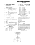
1
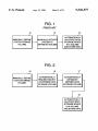
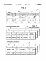
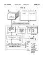
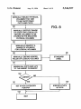
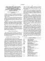
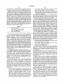
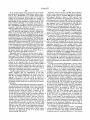
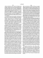
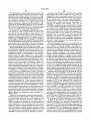
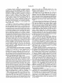
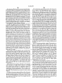
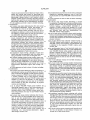
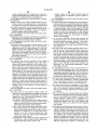
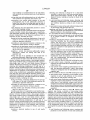
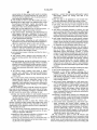
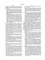
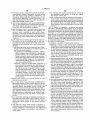
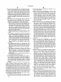
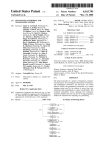
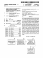
1|l||lllllllllIllllllllllllllllllllllllllllllllllllllllllllllllllllllllllll
USO05546557A
United States Patent 119]
[11]
Patent Number:
Allen et al.
[45]
Date of Patent:
[54]
INCLUDING AUTOMATICALLY CREATING
“MS-DOS operating system”, pp. 149-160, 1991.
“Introduction to IBM Direct Access Storage Device.” 1990,
LOGICAL VOLUNIES IN PERIPHERAL DATA
STORAGE SUBSYSTEM
“Dictionary of Computing”, 1987, pp. 276, 462-464.
[75] Inventors: Vincent K. Allen; Robert S.
“Isol IEC 10288” pp. 194-204.
A
an of Tucson Ariz-
.
E aminer_Thomas C Lee
W
x
.
'
sszstant Exammer-Moustafa Mohamed Meky
’
_ I
Attorney, Agent, or F1rm—M. W. Schecter; D. A. Shrfnn; H.
Assignee: International Business Machines
F‘ somermeyer
COI‘POl‘??OIl, Armonk, N.Y.
[57]
NO; 75,936
[21] AppL
_
Jun- 14, 1993
[22] Fllcdi
6
[51] 31
"""""""""""""
[52] ‘ ' ‘
47 3_ 364/248 1_ £64048 2f
’
pp. 5-8 to 5-9.
Prima
Goncharsky; Richard A. Ripberger,
' ’
' ’ 364ml
_
1’
'
ABSTRACT
peripheral data storage subsystem has means for respond
mg to a MOUNT command received from a host processor
to create and mount a host-processor-addressable logical
data-storage volume. Such logical data~storage volume has
a serial number VOLSER indicated in the MOUNT com
mand. The logical data volume is assigned a predetermined
area of a physical data volume, such area being termed a
partition. The illustrated embodiment shows a tape sub
Fleld of Search ................................... .. 395/275, 425,
System in which the partitions are accessed by a control
395/600’ 6501 438’ 404’ 823; 369/34
R f
C, d
using a reel tachometer that identifies segments of the tape.
Each partition has a number of the tape segments. Controls
8 erences
M
and methods are described for initializing the subsystem for
U‘S_ PATENT DOCUMENTS
eifecting the automatic volume creation, appending data into
_
a logical volume, how logical volumes are made to be
Slit-on at
,
Aug. 13, 1996
OTHER PUBLICATIONS
SYSTEM FOR STORING AND MANAGING
PLURAL LOGICAL VOLUMES IN EACH OF
SEVERAL PHYSICAL VOLUMES
[58]
5,546,557
,
1
------------------------ " 33695;]620g
igane
.
.
4,430,727
2/1984 Moore et a1. ......... .
4,837,680 6/1989 Crockett et a1.
4,989,191
1/1991
5,013,060
5,129,088
5/1991 Gelb er a1_ __
7/1992 Auslander ____ __
Kuo . . . . . . . . . . . . . . . .
395/442
395/284
. . . . ..
369/33
395/600
395/700
5,163,134 11/1992 Kakuse et al. ..
Hammg BI 81- - - - - -
395/823
5,197,055
3/1993
5,210,866
5/1993 Millig?n 91 a1
5,239,650
8/1993
5,283,875
5,287,500
5,327,535
2/1994 Gibson et al
395/404
2/1994 Stoppani,Jr. ..
395/600
7/1994 Oguta et al. .......................... .. 395/440
Hartung et a1
. ... .
-
-
Emma’
tapelfognzztse lusalbfl
forlsuch mg?“ Pumas’ ‘Siam
a” “intro 0
‘Tgw "0 “me? a“ ."0 “me “ea °n
1x09655199
The
PhYSIC‘TJ
volume
1“
whlch
one
or
more
log1cal volumes reside is not host-processor addressable.
Some physical volumes are ejectable from the data storage
subsystem. The physical volumes storing the logical vol
- - - - - t - - -- 369/34
urnes are not ejectable. To eject a logical volume, it is copied
395/ 182-04
from the storing physical volume to an ejectable physical
. . . . . . ..
395/650
volume‘
65 Claims, 11 Drawing Sheets
15
16
17
/
/
/
MANUALLY DEFINE
A DATA STORAGE
VOLUME
portable, moving logical volumes amongst diverse physical
AUTOMATICALLY
REQUEST MOUNT
OF DEFlNED DATA
STORAGE VOLUME
AUTOMATICALLY
ESTABLISH
DEFINED DATA
STORAGE VOLUME
18
/
AUTOMATICALLY
ALLOCATE DATA
STORAGE SPACE
IN A VOLUME
AND STORE DATA
US. Patent
Aug. 13, 1996
Sheet 1 of 11
FIG. 1
PRIOR ART
10
12
/
MANUALLY DEFINE
1S
/
MANUALLY ACTUATE
A DATA STORAGE
SYSTEM TO
VOLUME
ESTABLISH VOLUME
/
AUTOMATICALLY
ALLOCATE DATA
' STORAGE SPACE
IN A VOLUME
AND STORE DATA
Fl G. 2
15
16
11
/
/
/
MANUALLY DEFINE
A DATA STORAGE
VOLUME
AUTOMATICALLY
REQUEST MOUNT
OF DEFINED DATA
STORAGE VOLUME
AUTOMATICALLY
ESTABLISH
DEFINED DATA
STORAGE VOLUME
18
I
/
AUTOMATICALLY
ALLOCATE DATA
STORAGE SPACE
IN A VOLUME
AND STORE DATA
US. Patent
Aug. 13, 1996
Sheet 2 of 11
5,546,557
PRIOR ART
20
21
22
/
x
/
FID
24
/
DATA STORED IN BLOCKS
/
/
I
BOV
/
(23
I
LBOV
LEOV
/
k
PEOV
BOV - BEGINNING OF VOLUME
LBOV - LOGICAL BEGINNING OF VOLUME
LEOV - LOGICAL END OF VOLUME
PEOV - PHYSICAL END OF VOLUME
FID
- FORMAT IDENTIFICATION BLOCK
HUB
32 33
/
I
/
I]
33A
/
I
I
FID
(\
34
35
/
II
/
I
|
FID VOLIUME
|
l 1 I
(
I
\
[I
FID
/
I\ \
BOPLBOP
\EOD \BOPKEOD BOP)
PEOP
EOD
36
/
I
/ 38
I
l
\I
I
VOLUME FID VOLUME
a
[I
\\
3g
/
I
END
\) x
I I I
|
|
\ 37
EDD
31
PEOP
BOP
FREE OR
LEADER END
LEOP
BOP
- BEGINNING OF PARTITION
LBOP - LOGICAL BOP
EOP
LEOP
END OF PARTITION
LOGICAL EOP
US. Patent
Aug. 13, 1996
Sheet 3 of 11
5,546,557
/
,30
i _________ _ "3T1'>
___________ ' '3},'''''' " '1
l
PRV\
:(a
l
\ \
:/—-~
/
l
|
315
I
:&
IL
s30
\<- \
5
330
\-~
\s15
V
312
A
330
\\ -~
321
PVP PORTION OF DATA BASE
s3
~
l
w
330
\\ -~
320
65
/
~
\
k
\a1a
FIG. 7
PERIPHERAL DATA BASE
\
\
vouo
LV INDEX CATEGORY DATE/TIME
MOUNTED
AFFINITY TYPE
LIB
HISTORY
£832;
LAST
USE
LV PORTION OF DATA BASE
JOB
,0
66
74
\
/
73
72
\
\
VOLSER
VOLID
OU
START
PRV
STOP PRV
PARTITION
N0.
MOUNT MREQNT HISTORY JOBID DATE/TIME
:
l
ea
s7
'I'l
——318 7?:l
313_\_ N316
_
V
sso ‘
CAT
POINTERS
:
:
U.S. Patent
Aug. 13, 1996
Sheet 4 0f 11
5,546,557
FIG. 6
45
w
UME
mw“ML VH 00 Mamm
%
m
m
M
H/
HOST
PROCESSOR
MOUNT VOLSER(S) DRIVE CATEGORY
48
V
R
was
L
WALHWGM
WOTnluE PWLMO
5WACF WEE.CATD8
OAC
U0ESE8OP “CGLS(E 0OnTROn
M“RL
A
M
U
m/
EIUG
PRE
.WTQ
PmPOL
F
HY
L
U
M
W
YB
WAD7\P
OVOVU_EASU MUT“WORPGLm_MmMTh
RV_CPV PMH_VWVWMP.YPLR
M
EN
A_
E
_
E
..
pmmpv.
W\_
AW
KW\WM
m,HVM
_
M
NAT GEDS
(BEmW
L
_DTORVS
C
DEOM_EMED
.N
0
W
MC
_ D_Iw_
%1/0
- VOLUME ID
EXTERNAL
VOLSER - VOLUME SERIAL
NUMBER
INTERNAL
US. Patent
Aug. 13, 1996
Sheet 5 0f 11
5,546,557
92
\
MANUALLY SELECT PHYSICAL
VOLUMES THAT ARE
TO BE PARTITIONED
PVP‘S AND PVO'S
93
FIG. 8
MANUALLY SPECIFY RANGE
OF SIZES FOR LOGICAL OR
VIRTUAL VOLUMES TO BE
STORED IN THE SELECTED
PHYSICAL VOLUMES
94
\
I
MANUALLY IDENTIFY A
RANGE OF VOLSER'S
FOR LOGICAL VOLUMES
95
\
96
/
MANUALLY DEFINE HEADER
FIELDS OF LOGICAL VOLUMES
_
STANDARD
LABEL
ASSIGN ALL PVP'S AND LV'S
TO THE INSERT CATEGORY
1 00
NO
101
\
YES
103
/
SET STACK CATEGORY
FOR PVP
IDENTIFY PVP'S
& PVO'S
I
102
\
v
EXIT
l
US. Patent
Aug. 13, 1996
110
Sheet 6 of 11
5,546,557
PHYSICAL ONLY
\
o - (10K - 1)
PvC
111
\
we
PARTITICNED VOLUMES
F161. 9
10K- (100K- 1)
VOLUME RANGE
“a
150
\
LV‘S 100K+
152
. \
ASSIGN To
SCRATCH
VCLSERISI
15a
\
PRICRITY
155
156
157
158
\
\
\
\
DEvICE
voLSER(S)
TARGET
ADDRESS
VOLID(S)
LCCATI0N(S)
160
161
163
164
165
\
\
\
\
\
LCCATE
DEvICE
ADDRESS
M'GRATE
C
P
BLOCK NUMBER
PARTITION
NUMBER
PHYSICAL
REFERENCE
VALUE
CTRER PARAMETERS
\
\
110
172
CHANGE
DEvICE
REE/3mg’;
oTHER
SEGMENT
ADDRESS
VALUE
FIELDS
\
\
\
\
180
181
182
171
U.S. Patent
Aug. 13, 1996
5,546,557
Sheet 7 of 11
120
\
REQUEST HOST PROCESSOR
TO CREATE DATA STORAGE
SPACE FOR A DATA SET
121
FIG. 10
\
AUTOMATIC CLASS SELECTION
122
127
\
/
HOST PROCESSOR ISSUES
MOUNT COMMAND
VOLSER EXIST?
YES - SELECT PVP STORING LV
123
NOT EXISTI FIND PVOL THAT CAN
CONTAIN LV, THEN CREATE LV
\
PVM SEARCHES FOR VOLSER
IF NO VOLSER, SELECT PVOL
FOR CREATING AN LV
PVP SELECTION CRITERIA
CATEGORY FILTER
AFFINITY FILTER
EXPIRATION DATE
MOST FREE SPACE
CURRENTLY MOUNTED
MOUNT PVP TO DRIVE
'
141
/
131
\
POSITION TAPE TO PRV
FIND EMPTY
PARTITION
FOR THE LV
SELECT PVP
FROM THE
STACK
CATEGORY
146
/
/
132
RECORD FID
133
\
HOST PROCESSOR
COMMANDS REWIND
AND UNLOAD
134
\
PVM UPDATES DB
AND STORES PVOL
147
/
RECORD FID 32
RECORD PH 33
(HDR1)
US. Patent
Aug. 13, 1996
5,546,557
Sheet 8 of 11
PVP - PHYSICAL VOLUME -
PARTITIONED
PVO - PHYSICAL VOLUME -
ONLY
MIGRATE
FIG. 1 2
SELECT MIGRATION
PHQCESSMG
PVP TO LIBRARY
LV’S
202
\
21 s
/
I
PRIOR ART
MIGRATION
SELECT TwO
DEVICES
2/03
21\6
~
MOVE PVP TO
IO STATION
LOAD Two
PVP’S
I 217
\
'
204
/
MOVE LV'S
2&8
DONE
MOVE PVP TO
STORAGE
CUBICLE
NO
YES
209
2
\
UPDATE
DATA BASE
IMO
I
US. Patent
Aug. 13, 1996
Sheet 9 of 11
5,546,557
LOCATING BLOCKS IN LV’S
READ BLOCK ID
225
LOCATE BLOCK ID
230
\
BLOCK ID COMMAND IS ISSUED
TO FIND LOGICAL BLOCK
AFTER WHICH DATA BLOCKS
RECEIVE LOCATE BLOCK ID
COMMAND HAvING THE FIRsT
STARTING PRv
wILL BE ADDED
231
\
226
\
PVM READs THE sTART PRv
FROM FIELD as IN THE
DATA BAsE
‘
SUBSYSTEM RETuRNs TO HOST
PROCEssOR THE PHYSICAL
REFERENCE INDEX AND THE
23\3
NUMBER OF THE LOGICAL BLOCK
PVM CHANGEs THE
RECEIVED sTART PM
TO THE DATA BAsE PRv
227
\
'
HOsT PROCEssOR sAvEs THE
PARAMETER 'NFORMAT'ON FOR
LATER FINDING DATA BLOCKS
TO BE APPENDED ON TAPE AFTER
THE IDENTIFIED LOGICAL BLOCK
234
\
PSC CALCuLATEs THE SEGMENT
SIZE BAsED ON DIRECTION BIT.
ADJUSTED SEGMENT NUMBER
FOR CONTROLLING HIGH
SPEED sEARCH
235
\
LOCATE BLOCK ID COMMAND
Is EXECUTED AS A
HIGH SPEED SEARCH
US. Patent
240
Aug. 13, 1996
Sheet 10 of 11
5,546,557
FI G. 1 4
\
PVM DETECTS ACCESS
REQUESTS TO TwO LV'S
IN ONE PVP
FIG 1 6
241
'
\
260
\
SEND NOT READY
SIGNAL To HOST
PVM DETECTS ACCESS
242
\
REQUEST CONFLICT
TO MULTIPLE LV'S
W A FIRST pvp
SELECT A TARGET PVP
HAVING THE SAME
CATEGORY AS SECOND
REQUESTED LV(S)
24s
2
I
MOUNT TARGET PVP(S)
63
\
SEND UNIT CHECK TO
FIRST REQUESTING HOST
247
\
SEND LONG BUSY TO
‘
264
THE ORIGINAL HOST
\
244
-
\
I
IN HOST PROCESSOR
WAIT
COPY SECOND LV(S)
ABORT CURRENT JOB
FROM FIRST PVP TO
RESPECTIVE MOUNTED
ABORT NEw JOB
TARGET PVP(S)
245
\
‘
EXIT
UPDATE DATA BASE
246
\
I
SEND MOUNT COMPLETED
RESPONSE TO SECOND
REQUESTING I-IOST
PROCESSOR
248
\
SEND No LONGER BUSY
TO ORIGINAL REQUESTING
HOST PROCESSOR
US. Patent
Aug. 13, 1996
Sheet 11 of 11
5,546,557
FIG. ‘I8
300
FIG. 17
305
APPEND DATA
280
WRITING DATA
IN AN LV
306
301
307
SEND uc TO
WRITING HOST
283
END OF FILE
(EOF)
284
/ P801
251
P802 /
FIG. ‘I5
252
/253
DVE
5,546,557
1
2
SYSTEM FOR STORING AND MANAGING
PLURAL LOGICAL VOLUMES IN EACH OF
SEVERAL PHYSICAL VOLUMES
INCLUDING AUTOMATICALLY CREATING
LOGICAL VOLUMES IN PERIPHERAL DATA
STORAGE SUBSYSTEM
storage, the VOLID is repeated internally in the physical
volume as a machine-readable copy of the VOLID. Each LV
has an internally stored VOLSER that identi?es it as a data
LA
DOCUMENTS INCORPORATED BY
REFERENCE
storage volume.
A logical volume is a data storage volume that is addres
sable by a host processor independently of which physical
volume is storing it. The volume identi?er VOLSER of each
logical volume is independent of the physical volume iden
ti?er VOLID and is usually not externally available on the
physical volume.
Clifton et al US. Pat. No. 4,310,883 is incorporated for its
showing of a host processor allocating data storage space in
A physical volume - - - partitioned (PVP) is a physical
a virtual volume selected from a group of such virtual
volume that is divided into a plurality of physically-identi
(logical) volumes.
?able partitions, each partition is logically co-extensive with
Gelb et a1 U.S. Pat. No. 5,018,060 is incorporated for its
showing of a host processor using automatic storage class
selections for enabling enhanced data storage volume selec
tion in allocating data storage space in a data storage volume
a single logical volume. That is, one partition has one logical
partition. The medium physical locations in the physical
cal reference values (PRV’s) useful for rapidly accessing
cal only or PVO.
volume that may or may not completely occupy the one
volume are addressable by means external to the physical
volume as addressable segments. Each partition/logical vol
for a data set.
ume consists of an integral number of contiguous segments.
20
Milligan et al US. Pat. No. 4,393,445 is incorporated by
Partitions may be of ?xed length or variable length. An
reference for its showing of a peripheral data-storing tape
unpartitioned volume is a physical volume that has one
subsystem in which the subsystem generates and uses physi
partition. Such a physical volume is termed as being physi—
blocks of data stored in any one of a plurality of magnetic
tapes.
25
A partition is a portion of a physical volume that is
machine-identi?able either by machine-sensible marks on a
Co-pending commonly-assigned application for patent by
medium constituting the physical volume or by machine
sensible positions (with or without marks on the medium) of
Kulakowski et al Ser. No. 07/816,590, ?led Jan. 3, 1992,
now US. Pat. No. 5,303,214 is incorporated by reference for
its teaching of a?ine groups of data sets and data storage
volumes, logical or physical, in a multi-media automatic
such medium. For sensing machine-sensible positions of a
tape physical volume, as shown in Milligan et al, supra, a
media library data-storing subsystem.
volume measures tape displacement of the tape in the tape
tachometer of a tape drive that mounts a tape physical
FIELD OF THE INVENTION
This invention relates to peripheral data storage sub
35
system, more particularly to such subsystems that can auto
volume past a transducer for enabling machine sensing the
current portion of the tape being scanned by the transducer
in the tape drive. For interchange of each tape physical
volume between diverse tape drives, appropriate tape-mo
tion tolerances are accommodated in de?ning partitions of
each tape. A partition is not directly nor explicitly address
able by the host processor in a PVP, only the LV is
addressable.
matically create data~storing logical or virtual volumes and
the management of such volumes without any or a minimal
host processor intervention.
GLOSSARY AND DEFINITIONS OF TERMS
The following terms are used in this document:
A data storage volume or volume is a unit of a data storage
medium that is separately addressable and is identi?ed by a
volume identi?er. As used below, only for the purpose of
consistency in terminology, the volume identi?er for a
GLOSSARY of ACRONYMS
ACL
45
logical volume is termed VOLSER while the volume iden
ti?er for a physical volume is termed VOLID. In the prior art
VOLSER and VOLID have been used interchangeably. To
c?’ect access to data storing locations in a volume, a host
processor requests that an addressed volume be mounted in
an addressed device for accessing data storage space of such
Automatic Class Selection
ATL
Automatic Tape Library
CAR
Category
or CAT
FID
Concurrent or con?icting Access Requests
Code assigned to a PV, VV or LV de?ning an
attribute of the respective volume
Format Identi?cation
FSID
Format Segment Identi?cation
HDRl
Contains the VOLSER the LV, in a STACK
category PVP or an empty LV, I-IDRI contains
a speci?c code indicating that the volume
contains no data.
I/O _
volume.
LBOP
A physical volume is a volume that is always a physical 55 LBOT
LBOV
package, such as a tape cassette or cartridge, a disk cartridge,
LEOP
and the like. Each physical volume is independently mount
LV
able into a device to provide access by a host processor to
its data storage space. In the prior art, such physical volumes
are directly addressable by the host processor. In practicing
this invention, a plurality of logical volumes (LV) are
located in, but transportable from, a physical volume. To
access data storage space in a physical volume having LVs,
only the LVs are addressed by a host processor. This
physical volume is not separately directly addressable by a
host processor. The volume identi?er VOLID on a physical
volume is readable by a human being. In the prior art data
Automatic Cartridge Library
ACS
PBOP
PBOT
PEOP
PEOT
PRV
Input-Output
Logical Beginning of Partition
Logical Beginning of Tape
Logical Beginning of a Volume (PV, VV or LV)
Logical End of Partition
Logical Volume
Physical Beginning of Partition
Physical Beginning of Tape
Physical End of Partition
Physical End of Tape
Physical Reference Value of a tape physical
volume, used to identify locations of LV’s
in a PVP. This quantity is also term a
Physical Reference Index (PR1).
65
PVO
PVP
Physical Volume -- Only (one addressable
volume as in the prior art.
Physical Volume -- Partitioned into logical
5,546,557
3
4
-continued
The volume image is no longer externally identi?able
such that some component of the host/library system
must maintain a mapping of logical volumes to physi
GLOSSARY of ACRONYMS
cal volumes. This mapping information is a critical
volumes LV
Segment
The physical portion of a tape that is
system assist which must be highly available, highly
reliable, and disaster recoverable.
Logical volumes in a same mounted physical data storage
addressable by a tachometer on a tape drive
spool
Segment No.
The PRV value that enables addressing a
SEGNO
logical volume by segment
Segment number (see Segment No.)
VOLl
Contains the VOLID for the PV
VOLID
VOLSER
Physical Volume Identi?cation
Volume Identi?cation (serial number) for
volume are not concurrently accessible. When there are
requests to simultaneously mount a plurality of logical
volumes stored in a same physical volume, either all
but one of the mounts must be deferred, possibly
creating a data processing deadlock. An alternative is to
move all but one of the logical volumes from the one
a virtual or logical volume
physical volume to other physical volumes. If a data
movement solution is chosen, access to any data on the
BACKGROUND OF THE INVENTION
The average size of data sets in most computer or data
processing centers is signi?cantly less than the capacity of
tape or optical data-storing disk volumes. Also, most pro
20
one physical volume is delayed while the copies are
made. This solution may not always be practical for
many data processing environments.
Access to the ?rst byte of data stored in a physical tape
volume may be slower than if but one logical volume
gramming support for peripheral data storage subsystems
is stored in each physical tape volume. That is, since the
does not provide a general solution to storing multiple data
beginning of any logical volume is usually displaced
sets in the same volume, particularly tape volumes. Conse
from the normal loading point, the tape has be to moved
to position the beginning of a logical volume at the tape
quently, the potential capacity of tape storage is often not
realized because a single small data set is stored in one tape 25
volume leaving the remainder of the volume unused.
With the advent of automated tape libraries (ATL), the
cost of this unused storage includes, not only the percentage
of the volume which is not utilized, but also the cost of
storing that unused medium in the ATL. Tape products and
their associated software support which develop mecha
nisms which can fully utilize volume capacities will, in
general, have a signi?cant competitive advantage over com
parable products which cannot fully utilize volume capacity.
One possible mechanism to better utilize the capacity of
a tape volume is to store multiple volume images, virtual or
logical volumes (LV), on a single physical volume. For
better utilization of data—storage space, the data which would
drive transducer or head.
Depending on how data storage space is managed for
logical volumes (each addressable logical volume is
stored in a “partition” in a physical volume), the size
30
(number of data bytes) of a logical volume (data
storage space required for a logical volume must
accommodate volume size) can be expected to be
unpredictable. One solution is to prevent appending
35
data to data currently stored in a logical volume that is
“?rll”. Such partitions as used herein, are logically
co-extensive with logical volumes. High speed
searches on the tape are based on segments or position
reference values (PRVs), as will become apparent and
as set forth in Milligan et al, supra. Some prior art
have been stored in multiple, mostly unused, physical vol
documents use the term “partition” in a same vein as
the term “segment” is used herein.
umes are collected into a single physical volume. Such data,
in accordance with this invention, are stored in separately
To solve the above-‘stated problems, as well as other
addressable host-processor de?ned logical data storage vol
problems, using current day data storage management prac
umes. Access to the ?rst byte of data in such logical or
tices requires an undue attention to assignment and storage
virtual volumes may be slower than the access to a ?rst byte 45 of data using the logical volume approach. It is desired that
of data in a single physical volume. In the logical volume
the current practices in host processors and manual proce
case the beginning of the logical volume is generally some
where away from the normal tape loading point. This fact
dures required by attending personnel not be made cumber
means that before the ?rst byte of data in a logical volume
methods for storing a plurality of logical data storage
volumes in one physical data storage volume wherein the
is accessible, not only is the physical volume mounted but
the logical volume has to be found by moving the tape to
place the logical volume at the tape transducer. Also, con
current con?icting access requests to multiple logical vol
some. Therefore, it is desired to provide mechanisms and
50
attending personnel do not change for de?ning volumes. It
is desired to eliminate the current need for de?ning and
umes residing on the same tape have to be resolved.
It is also desired that the host processor and/or personnel
operating the host processor have no activities that relate to
storing a plurality of volumes of data in one physical
volume. In the prior art, manual control is required for
creating or establishing a de?ned or requested data storage
volume. It is desired to limit the required manual steps to
data management activates in a host processor and of the
55
assigning which physical data storage volume is to be used
for storing any given logical volume and to eliminate a
current need for assigning a physical volume for storing data
before that data are sent to a data storage system. In other
words, the management of data storage volumes is trans
parent (not seen) by either the host processor nor its attend
60
ing personnel.
merely de?ning each desired volume and for inserting
scratch physical volumes into an ATL or open shelf storage.
The bene?ts of this enhanced capacity utilization without
DISCUSSION OF THE PRIOR ART
host processor nor personnel involvement greatly simpli?es
and obviates the need for personal attention to a data storage
system. However, these bene?ts come at the expense of
creating additional problems which must be handled, that is:
Clifton et al in US Pat. No. 4,310,883 describe a mass
65
storage system wherein one disk volume (IBM 3330 disk
volume) was emulated by two tape cartridges in an auto
matic cartridge library (ACL). The disk volumes are termed
5,546,557
5
6
“virtual volumes” even though the system is a one-for-one
establish each and every such logical volume or disk. That
is, no automatic means have been shown for automatically
creating or establishing a logical volume LV or logical disk.
emulation of two tape cartridges for each disk volume.
Clifton et a1 host processor automated emulated disk volume
selection using a best ?t detector. All emulated disk volumes
were established by manual actuation of the system before
the Clifton et al automated volume selection could be
invoked. The emulated disk volumes are grouped into so
called volume groups. Clifton et a1 grouped virtual volumes
The DICTIONARY OF COMPUTING, IBM, Eight Edi
tion, 1987, pp 276 and 462-464 de?ne some of the terms
listed above. The term “minidisk” on page 276 includes the
synonym of “virtual disk”. The term “virtual disk” is de?ned
on page 462 as being either a so~called RAM disk (in main
storage) or a “logical subdivision of, a physical disk storage
device that has its own address, consecutive storage space
for data, and an index or description of stored data so that the
data can be accessed.” Again, each and every one of such
“virtual disks” are individually established via a separate
into “volume groups” by user (manual selection, input to the
primary host processor) chosen criteria. Such criteria are
application area, common retention period and space allo
cation quantities. One volume group could not be subordi~
natcd to another volume group. A best ?t volume selection
criterion included several volume attributes, such as volume
manual actuation of the data processing system.
An example of manually actuating a data processing
expiration date being later than a data set expiration date,
available free space and the like. Once each data set is
assigned to a given emulated disk volume, allocation and
storage activities ensued.
Gelb et al in U.S. Pat. No. 5,0l8,060 extended the
automation of volume selection started by Clifton et al. Gelb
ct 31 provide for inferred or implicit automatic volume
selection based upon three data/volume de?ning class
system for establishing a virtual disk or a minidisk is set
forth in the Microsoft MS-DOS User’s Guide and Refer
ence, Version 5.0, 1991, in pages l49—160. These pages
describe a DOS utility program FDISK provides an operator
20
interface for establishing “virtual disks”. That is, one physi
cal disk is divided into a manually indicated number of
“partitions”, each partition being addressable as a separate
attributes. A DATA class includes user de?ned data
virtual disk. The program is usually used for disks that are
attributes. A STORAGE class de?ned user inputted perfor
mance and other storage related parameters, viz capacity,
not removable.
access time etc. A user de?ned MANAGEMENT class 25
related to scratching volumes and data sets and the like. The
Milligan et al in U.S. Pat. No. 4,393,445 show generating
a physical reference value (PRV) based upon tape displace
ment past a transducer. Such PRV’s are not separately
three classes are used to select a volume identi?ed in one or
indicated on the tape. Rather, spool rotation is used to
measure tape displacement for identifying the PRV numbers.
According to Milligan et al, such PRV numbers are usable
by a host processing to quickly move to a desired tape
more STORAGE groups of volumes. A primary purpose of
Gelb et al apparently is to automatically assign data sets to
data storage volumes based on established criteria (classes)
that use inferences or hints identifying the data set to select
a data storage volume. Gelb et al, like Clifton et al, use
displacement position (locate recorded data blocks) or for
error recovery purposes. Milligan et al also teach that a PRV
is usable for indicating status of a data buffer that stores data
35 to be either written to or has been read from a magnetic tape.
The IBM Technical DisclosureBulletin, Vol 35, No. 5
Such PRV values respectively denote reference points on a
October 1992, pp 17-20, describes improving data-storage
magnetic tape that are generated and indicated by means not
volume management by using categories. A category is
on the tape, i.e. there are no marks showing such PRV’s on
de?ned for including data-storage volumes having a com
the tape. The present invention uses the PRVs to indicate
mon attribute. Such common attributes include scratch vol 40 media segments. One or more segments are combined into
umes, expiration dates, common user, type of volume,
a logical volume that is said to occupy one “partition” on the
host-processor data related to a job or a set of Jobs, volumes
storage medium, i.e. one partition as that term is used to
to be transferrer or migrated to a scratch category, and the
“partition” hard disks used with DOS and 08/2 operating
already established volumes based on manual actuation of
the system to recognize such physical or emulated volumes.
like. A mount by category is indicated as mounting any
volume that is a member of a category. One example is
systems.
A proposed Small Computer Standard Interface (SCSI)
mounting one volume from a scratch category.
standard, ANSI document ISO/IEC 10288 - ~ - ANSI
Co-pending commonly-assigned application Kulakowski
X3.131:l992R, Nov. 16, 1992, in pages 190—204 describes
partitions on a magnetic tape. Such partitions are compa
et al Ser. No. 07/816,590, ?led Jan. 3, 1992, now U.S. Pat.
No. 5,303,214 shows an automatic media library subsystem
that uses an aflinity characteristic for managing data-storage
volumes. That is, those data-storage volumes storing data
that have a predetermined functional relationship (host pro
rable to “segments” described herein, i.e. physical portions
50
of the tape that are addressable by means external to the tape
(enable the tape to be transported in a high speed positioning
operation without contact with the tape). Such high speed
positioning, as taught by Milligan et al, supra, is preferably
cessor determined) have an affinity. Af?nity classes are
established. Cartridges that are members of a same a?inity
a tachometer on a reel mount in a tape drive. Section 10.1.3
class must be entered and exited from me library as a unit. 55 (page 192) of the ANSI document describes a proposed
The storage location of the cartridges having such an af?nity
standard for “partitions within a volume”. Partitions, sic
is preferably in close physical association in the library
segments, consist of one or more non-overlapped tape areas.
storage compartments. It is desired to extend the Kula
Each partition (segment) has its own beginning and ending
points. In each magnetic tape volume (one reel of tape),
every partition has a de?ned beginning-of~partition (BOP x),
an early-warning position (EW x) and an end-of-partition
(EOP x), where x is the partition number. The partition
kowski et al allinity control for better managing logical
volumes having such an a?inity for enhancing accessing the
60
various logical volumes depending on the nature of the
a?inity.
The terms “virtual volume” and “logical volume” have
been used to denote identifying a portion of a storage
medium as an addressable entity. Also, the term “minidisk”
has been used to mean “virtual disk”. All of this usage has
required a manual actuation of the data processing system to
(segment) numbers need not be recorded on the medium.
Milligan et al do not mention the early-warning or end-of
65
partition format blocks. For interchange, information about
which partitions (segments) are present in a magnetic tape
volume may be stored in the volume in a device-de?ned area
5,546,557
7
8
or such information may be an intrinsic attribute of device
ume usage or LV usage. Diverse media, such as magnetic
implementation. What such information consists of is not
de?ned in the SCSI document. That is, the standard does not
tape, optical tape, magnetic disks or optical disks may be
employed, alone or in a mixed media library.
address how such partitioning could or should be accom
The foregoing and other objects, features and advantages
plished. The SCSI document does indicate that tape move
ment between partitions (segments) has no stable position,
i.e. exact position is not known as the tape transducer and
of the invention will be apparent from the following more
particular description of preferred embodiments of the
invention, as illustrated in the accompanying drawings.
tape are not in contact.
According to the SCSI document, each partition (seg
ment) has logical elements that include host processor
(initiator) elements of data and ?le marks, i.e. usual tape
formatting. Each unit of data is stored as a logical block.
Logical block storage is in accordance with the format being
used in the volume (entire tape, not in logical volumes on the
tape). A “setmark” is de?ned that is a mark superior to ?le
marks, i.e. there may be a plurality of ?le marks disposed
between a pair of spaced-apart setmarks in any partition
(segment). The SCSI document does not describe how such
partitioning (segmentation) is to be accomplished nor how to
manage a subsystem using such partitioning. See Milligan et
al, supra.
DESCRIPTION OF THE DRAWING
FIG. 1 illustrates known prior art volume creation/estab
lishment methods.
FIG. 2 illustrates a method for the creation/establishment
of data storing volumes in accordance with the present
invention.
20
of a logical volume in the FIG. 4 illustrated tape format and
the use of physical references for locating and identifying
multiple logical volumes on a tape including logical vol
SUMMARY OF THE INVENTION
The present invention being practiced in a data processing
system having a peripheral data storage subsystem causes
FIG. 3 illustrates a prior art magnetic tape format.
FIG. 4 illustrates, in simpli?ed form, a multi~volume tape
format constructed in accordance with the present invention.
FIG. 5 illustrates, in simpli?ed form, the logical elements
umes in a magnetic tape have a so-called serpentine track
25
the subsystem to respond to a MOUNT command received
from an attached host processor when no volume exists to be
mounted to create or establish a volume, then mount the
volume for responding to the MOUNT command. Such 30
volumes can be logical or virtual volumes established in a
physical volume, i.e. such as a reel of tape. The subsystems
manages the logical volumes (LV’s) in relation to the
physical volumes using a peripheral data base. Each physi—
cal volume can contain a variable number of LV’s. For 35
accessing the LV’s, physical segments are identi?ed in the
physical volume, preferably using PRV’s. Each PRV may
indicate a boundary between two longitudinally adjacent
segments. Each LV constitutes one partition of the physical
layout.
FIG. 6 is a simpli?ed block diagram of a data processing
system of the present invention.
FIG. 7 diagrammatically shows a peripheral data base
used in the FIG. 6 illustrated data processing system.
FIG. 8 shows a simpli?ed method for initializing the FIG.
6 illustrated data processing system.
FIG. 9 diagrammatically shows an exemplary volume
serial number (VOLSER) range of values for use in the FIG.
6 illustrated data processing system.
FIG. 10 shows a simpli?ed method for automatically
creating or establishing a logical volume LV in a FIG. 6
illustrated and initialized data processing system.
FIG. 11 diagrammatically illustrates an exemplary set of
volume. Each partition consists of one or more, preferably 40 peripheral or channel commands for use in the FIG. 6
contiguous, segments. The LV’s are accessible on a random
basis.
Two or more concurrent con?icting access requests for
di?erent LV’s in the same physical volume are honored by
copying one of the LV’s to another physical volume. Any
45
FIG. 13 illustrates locating a host processor addressed
block of a logical volume LV recorded in the FIG. 4
one of several methods are employed.
Appending data to an existing LV is monitored and
managed to ensure that the data being appended do not
illustrated magnetic tape.
unintentionally overwrite data already stored (recorded) in
the physical volume. In response to detected possible over
writing, the current writing is aborted, then another LV is
selected/created for receiving the data and the data are
rewritten into the newly selected/created LV.
It is preferred that the invention be practiced in an 55
automatic library environment. Ejection of LV’s from the
library is e?’ected by storing the LV in an ejectable physical
volume.
Categories, including categories based on af?nity charac
teristics, facilitate volume selection and management. The
categories de?ne characteristics that assist management of
the data, the LV’s and physical volumes.
Diverse media and data-storage track layouts can be used
in the physical volumes. The data storage subsystem may
contain physical volumes that store data only as a single
volume, physical volumes that contain one or more LV’s,
scratch physical volumes designated for either single vol
illustrated data processing system.
FIG. 12 illustrates in simpli?ed form exemplary machine
operations of the FIG. 6 illustrated data processing system
for migrating physical and logical volumes between diverse
data storage apparatus.
FIG. 14 illustrates machine operations of the FIG. 6
illustrated data processing system for accommodating con
current con?icting requests to a single physical volume for
multiple logical volumes recorded or stored therein.
FIG. 15 illustrates, in simpli?ed form an alternate to the
FIG. 14 illustrated accommodation to handling multiple
concurrent con?icting access requests to a single physical
volume for multiple logical volumes recorded or stored
therein.
FIG. 16 illustrates, in simpli?ed form, machine operations
60
of the FIG. 6 illustrated data processing system that include
execution of host processor software for handling concurrent
con?icting requests to a single physical volume for multiple
logical volumes recorded or stored therein.
FIG. 17 illustrates, in simpli?ed form, machine operation
in the FIG. 6 illustrated data processing system for append
ing data to data stored in a logical volume and for error
control as a logical volume becomes full of data.
5,546,557
10
9
The illustrated embodiment of this invention employs
FIG. 18 diagrammatically illustrates two optical disks in
which the present invention is practiced using the FIG. 6
illustrated data processing system and the illustrated meth
ods and structures shown in FIGS. 2, 7—12 and 14-17.
magnetic tape physical data storage volumes (PVPs) in
which the LV’ s are created/established. In the host processor
accessing or mounting such LV’s, the procedures are inde
pendent of whether or not the VOLSER has been created!
established. That is, the peripheral data storage subsystem
Referring now more particularly to the appended drawing,
responds to a host processor request to mount a data storage
volume (herein an LV) to create an LV having a VOLSER
indicated in a host processor issued mount command.
like numerals indicate like parts and structural features in the
various ?gures. FIG. 1 illustrates a prior art method for
netic tape 20 has a so-called system area 21 at a free or
DETAILED DESCRIPTION
FIG. 3 illustrates a prior art magnetic tape format. Mag
creating or establishing volumes, including logical or virtual
volumes. Step 10, a manual step, requires that the size of the
leader end of magnetic tape 20. The beginning of the tape
volume (BOV) is indicated by a format identi?cation FID
22. FID 22 is typically a non-data pattern that, inter alia,
indicates recording density, number of tracks, etc. of the
prior art magnetic tape. Boundary 23 of FID 22 marks the
logical beginning of volume LBOV. Area 24 of magnetic
tape 20 contains the recorded data arranged in physical
blocks of data. Logical end of volume LEOV indicates a
logical end of the storage portion of area 24. LEOV can be
indicated by a mark on magnetic tape 20 or be a PRV, such
as shown in Milligan et al, supra. The physical end of
volume PEOV indicates the end of the magnetic tape at the
hub end portion.
Included in the prior art usage of magnetic tape 20 is the
Milligan et al disclosed PRV’s based upon a reel tachometer
indication of tape displacement from a tape hub (not shown)
volume and other desired characteristics and attributes be
de?ned in computer readable form, such as in a unit record
card, terminal and the like. This step is like creating a
partition on a hard disk of a personal computer or a mini
disk in a data processing environment. The manual step 12
is the manually actuated inputting of volume attributes and
a command to create or establish a volume. Such creation in
data processing environments include a system generation
(SYSGEN) step for adding a tape drive, disk drive or other
volume (?xed in the drive) to the data processing installa
tion. SYSGEN is a known procedure that is usually effected
in slow periods of processing for avoiding unintended
interference with usual data processing activities. SYSGEN
enables a terminal to identify, one at a type, peripheral
equipment to host processors, and the like. The term SYS
GEN means “system generation”. Once the data storage
that enables faster access to the data blocks stored (recorded)
in area 24. Such PRV’s are also used to de?ne physical
volume is created/established in the data processor, auto
matic step 13 allocates data storage space to the created/
addressable via the reel tachometer counts, all as shown in
established volume. The documents incorporated by refer
ence illustrate such automatic allocation procedures.
In accordance with one aspect of the present invention,
FIG. 2 illustrates automatic creation/establishment of logical
data storing volumes. Included in the automatic creation/
segments of magnetic tape 20. Such physical segments are
Milligan et al. Each such segment is bounded by two
selected PRV’s generated by the reel tachometer. As taught
by Milligan et al, a separate tape displacement measurement
35
establishment of a data storing volume is an automatic
assignment of a volume serial number (VOLSER) to the
de?ned data storage volume. Both the subsystem and the
host processor must have knowledge of such VOLSER’s.
40
The procedure includes manual step 15 that is substantially
exemplary magnetic tape 30 format employing some
described aspects of the present invention. Such format
consists of partitions that are each identi?able by the Mil
ligan et al PRV system, each partition comprising one or
the same as manual step 10, i.e. a data storage volume is
de?ned in a host processor and a VOLSER is selected for the
de?ned data storing volume - - - at this point no actual host
processor addressable data storing volume exists. Instead of
system may be used. The present invention builds on the
teachings of Milligan et al to provide enhanced automatic
data storage volume controls using LV’s while simulta
neously enhancing usage of magnetic tape 20.
FIG. 4 illustrates, in simpli?ed diagrammatic form, an
45
manually inserting the de?nition of the data storage volume,
all that is required of the user is to automatically (step 16)
request (command) a peripheral data storage subsystem to
MOUNT the de?ned VOLSER data storage volume. This
more of the physical segments. Each partition, other than a
later-described ?rst or system partition, stores, i.e. is addres
sable as an LV, one logical volume. Such partitions are
dynamically generated in response to MOUNT commands
received from a host processor, as will be further described,
for storing one host-processor-addressable LV. Such a tape
automatic step is performed in a usual manner in a host 50 30 is termed a “partitioned” or “LV” data storing magnetic
processor connected to the peripheral data storage sub
tape, hereinafter referred to as a physical volume—parti
system. In step 17, the peripheral data storage subsystem
tioned (PVP). The prior art data storing magnetic tape 20 is
termed an “unpartitioned” or “physical only” physical vol
ume, hereinafter termed a physical volume only (PVO).
automatically responds to the MOUNT request to create/
establish a data storage volume having the VOLSER
assigned for addressing the data storage volume. Once the
data storage volume has been automatically established,
automatic step 18, usually performed in a host processor,
allocates data storage space in the VOLSER data storage
volume as performed in the prior art. Therefore, the attention
to details as required in the prior art is removed from manual
activity required in the prior art to create/establish an
55
magnetic tapes (PVPs) are assigned to a “stack” category.
These physical volumes are placed in the stack category
when they are to be made available to subsystem 48 for
60
another PVP. Therefore, one of the categories that PVP’s are
all assigned is the stack category. Unformatted magnetic
created/established data storage volumes are logical or vir
of VOLSER’s for facilitating orderly generation of LV’s.
“stacking” one or more logical volumes into one physical
volume. When a host processor attempts to remove a physi
cal volume from this category, the library causes any active
logical volumes on the physical volume to be copied to
addressable data storage volume.
In a preferred form of the invention, the automatically
tual volumes, hereinafter termed LV’s. As later detailed, the
peripheral data storage subsystem is initialized with a range
Unformatted magnetic tapes destined to become partitioned
65
tapes destined to become non-partitioned volumes PVO are
assigned to an insert category. These categories are neces
sary as the unpartitioned physical tape volumes PVO must
5,546,557
12
11
b) A so-called volume record that contains the volume
serial number VOLID of the physical volume.
0) An End of Data (EOD) mark at one end of PH 33. A
formatted PVP has the just-described format of one
be identi?ed by an VOLID (volume identi?cation) that is
both external (visual) and internal (magnetically recorded).
Magnetic tape 30 has system reserved area 30 at the free
or leader end of the tape. Since magnetic tape 30 is divided
into addressable partitions, each partition storing an LV, as
will become more apparent, format identi?cation FID 32 is
partition (partition 0) and not others. Therefore EOD is
at the end of partition 0.
In the library environment, this ?rst or PH 33 partition is
created and managed by the library and is used to validate
more extensive in informational content than the prior art
FID 22. The leader end of FID 32 is termed “beginning of
partition” BOP. The informational content of FID 32
includes whether the partitions on magnetic tape are of ?xed
or variable in length. PH 33 is a partition de?ning header that
that the correct physical volume has been mounted. This
veri?cation ensures both system and data integrity.
In each ?xed-partition sized partitioned or LV physical
volume, unused data storage space exists between each LV
that may contain residual data from prior recordings. Such
data are invalid and have to be ignored. In general, it is not
possible to read through these unused data storage spaces to
reliably di?erentiate residual (invalid) FID marks from
current and valid FID marks without knowledge of the
has information as set forth below. The combination of FID
32 and PH 33 completely de?nes the speci?c format of
magnetic tape 30. FID 32, PH 33 and area 34 constitute a PH
33 partition addressable by subsystem 48 and is not addres
sable by a host processor. PH 33 preferably includes the
information set forth in Table I below:
starting and ending segment boundaries. This segment
TABLE I
VOLID of the PVP
20
PRV’s of Partition 0 PBOP and PEOP
PRV‘s of Partition 1 PBOP and PEOP
boundary information is stored in PH 33. Once written PH
33 need never be updated since all partitions are de?ned
when the volume is ?rst formatted and before any partition
is logically created to make it addressable as an LV. Changes
to the partitioning sizes requires rewriting PH 33.
In the variable length partition or variably-sized LV
format, multiple partitions of variable length are created
PRV’s for all partitions 2. . . .N
EOD -- End of Data mark
LV’s for storing user data (such as in records numbered 25 after the PVP is initially formatted as a variable partition
PVP. Such variable-sized partitioning is such that a continu
l—N, N is a positive integer) are in partitions numbered 0
ous formatting from the beginning of the ?rst partition to the
through N, where N is a positive integer designation of a last
end of the last partition is provided. The ?rst or PH 33
partition created for a last LV in the PVP. The second
partition, numbered 0 consists of partition FID physical
partition on the volume contains PH 33 that contains a
Similarly, a third partition numbered 2 consists of FID 34
and volume area 35 and is longitudinally adjacent the second
a) A Variable Partition Mark (FPM) that indicates variable
length partitions exist in the PVP.
b) A so-called volume record that contains the volume
block or mark 33A and a data storing area 34 in which an LV 30 variable partition volume header having the following infor
mation and the information shown in TABLE I:
resides. Areas 33A—34 occupy one or more tape segments.
partition. Similarly, fourth partition numbered 3 and having
areas 37-38 resides next to partition 2. Numeral 39 indicates 35
that additional partitions having LV’s are appended to the
illustrated partitions up to the LEOV (not shown) of tape 30.
Each of the LV’s in volume portions 34, 36 and 38 of the
illustrated partitions have an EOD indicating end of data in
the respective LV’s.
In a magnetic tape 30 having ?xed size partitions, i.e. all
marks are in usual or so-called legal data pattern form.
Therefore, each of the marks is a physical data block having
40
information bearing signals respectively indicating a tape
mark, EOD, etc.
of the multiple partitions have like sizes in terms of numbers
In a library environment, this ?rst or PH 33 partition in a
variably-sized PVP is created when the PVP is to receive an
of segments in each of the respective partitions. Segments
may be used to “?nd” or “identify” partition boundaries. If
the segments have a suf?cient resolution, all partitions of
?xed sized should have the same data storage capacity. If the
segments vary in size with reel rotational positions (see
Milligan et al supra), then ?xed sized partitions can have
differing numbers of segments.
The ?rst partition in a tape in each ?xed-partitioned
physical volume contains a ?xed partition volume header
(PH 33). This ?rst partition preferably does not have any
system number, i.e. is not accessible by a host processor.
Therefore, there is no need for any system control marks,
such as tape marks in the PH 33 partition. PH 33 being in its
own partition is updatable by the subsystem. Each PH 33, as
partially shown in TABLE I above, contains the following
serial number VOLID of the PVP.
0) An End of Data (EOD) mark.
In the illustrated embodiment, all of the above mentioned
LV. The ?rst partition is then managed by the library (as later
described) for validating that a correct physical volume has
been mounted.
Whenever either a ?xed or variably sized partition is
created for an LV in any PVP, including the PH 33 partition,
50
the peripheral subsystem always formats the beginning of
the next partition by writing the following physical blocks in
such longitudinally adjacent unassigned segment (area 39
immediately adjacent to volume area 38) with an additional
FID Mark in a next segment (vacant) indicating a partition.
An EOD mark is recorded after the additional FID mark if
55
there are no additional recording on the tape further from the
beginning of medium or tape.
Again, note that the marks in the illustrated embodiment
information:
are each physical data blocks indicating the respective
a) A Fixed Partition Mark (PPM) that de?nes (in either a
indicated tape status, as end of partition, end of medium, etc.
list or a code representing a documented list) the 60
When a subsequent partition is actually created on the
boundaries of all existing partitions. The boundaries are
next longitudinal segment(s), the BOD mark (physical
identi?ed by segment boundary numbers. The ?rst
segment is numbered segment 1 and has two known
PRV’s that identify its boundaries. All partitions are
similarly indicated. Note that partitions, other than the
subsystem managed partition that contains PH 33 do
not exist until an LV is created for such partitions.
65
block) is overwritten with the VOL1 record (physical block)
for identifying the partition being created. The LEOM is
written just beyond the hub facing end of the created
partition in a next longitudinally adjacent segment (not yet
a partition) as part of creating/establishing by fonnatting
segments to be a next partition.
5,546,557
14
13
Optionally, each LV can have a VTOC. Such a VTOC is
In the variable logical volume format, there is no unused
data-storage space between longitudinally adjacent parti
I stored in a one-segment partition immediately preceding the
tions or LV’s. Modi?cation of a variable length logical
volume (other than the last logical volume on the physical
partition holding the LV. Numeral 330 between longitudi
nally adjacent partition’s denote a VTOC partition (one
segment) for the respective LV’s residing the respective LV
containing partitions. Numeral 318 indicates that a partition
volume) is not permitted. By precluding the creation of
residual data between the logical volumes, it is possible to
read through all tape segments and reliable detect all FID
marks without knowledge of the starting and ending seg
can extend between track half wraps. The diverse number of
tape segments in the LV holding partitions 316—321 indi
ment boundaries. To improve (decrease) access times to
LV’s, including the position of a next LV to be created, it is
cates that the data storage capacity of each partition is
independent of the storage capacity of other partition’s - - -
advisable to maintain a directory of the starting and ending
it is user de?ned and implementation dependent. The for
matting in each of the LV partitions is as described for FIG.
4. The FID of each LV holding partition can indicate whether
segment numbers within the library system.
In either the ?xed or variably sized partition tape formats,
each FID should be long enough to provide a landing zone
or not a VTOC for the LV is recorded in a longitudinally
adjacent tape partition. In this manner, in a same PVP some
LV’s may have VTOC’s while other LV’s have no VTOC’s.
Referring next to FIG. 6, one or more host processors 45
which can be accessed under worst case inter-drive posi
tioning tolerances. That is, the longitudinal extent of each
FID should be such that fast positioning using the Milligan
et al disclosed PRV’s will cause the FID to be found in a ?rst
locate block operation, as later described. The PEOP point
are connected to (attach) peripheral data storage subsystem
must be longitudinally positioned far enough away from its
48 using usual peripheral data channel attaching circuits and
adjacent BOP point to ensure that PEOP is detected under all
cables. A MOUNT command 49 can be sent by any of the
interchange conditions. Such spacing ensures against inad
host processors 45 to peripheral data storage subsystem 48
requesting mounting of a data storage volume. Such
vertent overwrite of user or control blocks upon overwriting
a next longitudinally adjacent partition begins. Even with
the spacing described above, each partition’s PEOP point is
logically coincident with a next partition’s PBOP point. See
25
MOUNT command includes the usual MOUNT command
indicator, the VOLSER(s) indicated data storage volumes to
be mounted, the address(es) of the tape drive(s) to mount the
respective data storage volumes, the category in which the
VOLSER’s are assigned to, any affinity characteristic (later
described), the expiration date EXPIRE of each of the data
the vertical double lines between areas 34 and 35 as the
PEOP of partition 0 and PBOP of partition 1.
Optionally, each LV may have its own volume table of
contents VTOC at the beginning (free end) of a partition. ‘
storage volumes to be mounted and a JOB ID that is a host
Since each VTOC must be updatable and addressable, then
two addressable partitions are required for each LV having
processor reference. In accordance with the present inven~
tion, subsystem 48 responds to the MOUNT command to
a VTOC; one partition for the VTOC and one partition for
create/establish an LV for each VOLSER identi?cation that
the LV. In a ?xed size PVP, each VTOC portion of an LV
consists of one segment while the LV portion partition
does not correspond to any data storage LV established in the
subsystem.
As usual, host processors 45 maintain a system volume
consists of one or more contiguous segments. The LV VTOC 35
catalog 50 indexed by VOLSER and having other data
reduces the time needed to determine volume contents. As
relating to the VOLSER (including a table of contents),
expiration date, etc. as is known. In practicing the present
such, each LV VTOC is a backup to directory data stored in
a data base containing this information, i.e. avoids a full scan
of the tape to reconstruct the directory information.
invention nothing, or a minimal informational content is
changed as to maintaining system volume catalog 50. That
Variable length partitions (LV’s) need not reside in con
is, each LV appears as a true addressable data storing volume
to the host processors that is mountable in a peripheral data
storage subsystem. Of course, data are included in catalog
50 indicating that the volume is a logical or virtual volume.
tiguous segments. This LV fragmentation on the tape
requires a VTOC at the beginning of the volume, such as in
area 34, for indicating beginnings and ends of each LV
fragment. The VTOC in this case would be required to
identify the partitions in the event that the data base con
taining this information was lost i.e. scanning the tape would
45
Peripheral storage controller PSC 52 (also termed control
unit, storage director, and the like) attaches the subsystem 48
to host processor 45. PSC 52 includes the usual data flow
circuits, error detection and correction circuits, data buffers
not provide reliable results for reconstructing the directory
information.
or caches, device attaching circuits, inter~PSC communica
tion circuits, and the like. A plurality of magnetic tape drives
FIG. 5 shows partitions and their relationship to segments.
In a tape having so-called serpentine tracks, the forward scan
direction represented by arrow 311, viz free end toward the
(hereinafter DVE’s) are attached to PSC 52 in a usual
manner. Physical media storage 54 receives, stores and
supplies PVOs and PVPs (storage media such as tape
extending between BOM and EOM) is opposite to the
cartridges, tape reels, etc.) from, for and to addressed ones
forward direction of scanning indicated by arrow 313, viz
from the hub end toward the free end, in a second or adjacent 55 of the DVE’s 53. In a preferred form of practicing the
present invention, storage 54 includes an automatic tape
set of a like plurality of tracks 312. Each set of tracks, such
library of usual design. In this preferred form, a medium
as four tracks, 310 and 312 is tcnned a “half wrap” while the
cartridge accessor (not shown) fetches PVPs from storage
entirety of the two tracks is termed a full wrap. That is, one
cubicles for automatic insertion into addressed ones of the
complete scan in a forward direction beginning at the free
DVEs. A usual long term manually service shelf storage in
end of tracks 310 to the hub end, thence from the hub end
proximity to the automatic library(ies) ATL or ACL is
of tracks 312 to the free end is one full wrap. The PRV’s 31S
provided. The operational relationship of such shelf storage
extend entirely across the tape 30 such that all tracks 310,
to the libraries will become apparent.
312 have a same PRV value in each longitudinal position of
hub end, in one set of a plurality of tracks 310 (tracks
tape 30. The space between longitudinally adjacent PRV’s
constitutes one segment of tape in each set of the tracks.
partition’s are represented in FIG. 5 by double headed
arrows 316,318, 320 and 321.
65
In accordance with the present invention, a peripheral
volume manager PVM 57 is added to subsystem 48. PVM
57 provides automatic data storage volume management
including automatic creation/establishment of data storage
5,546,557
15
16
volumes addressable by host processors 45 based upon
information contained in system volume catalog 50. Volume
PVO is not mounted. If the PVP or PVO has an assigned
map 58 is maintained and stored in a non-volatile RAM or
acteristic. The type ?eld indicates whether the PVP is a ?xed
sized partitioned or a variable sized partition physical vol
ume. The library ?eld “lib” indicates the address at which
a?inity characteristic, the a?inity ?eld indicates that char
data storage disk(not shown) by PVM 57. Map 58 includes
a plurality of entries, each entry including a VOLSER ?eld
for identifying data storage volumes, including all LV’s. The
the physical volume is stored in an automatic library. History
?eld may be used to indicate a recent history of the physical
VOLID of a PVP containing the respective LV is a second
?eld in map 58. Category CAT is a third ?eld. Usage of the
information in map 58 will become apparent. A subsystem
data base, shown in FIG. 7, is maintained for enabling PVM
57 to perform volume creation and management in the
subsystem. Map 58 may be a separate “cached” portion of
10
volume, such as mount history, LV additions/deletions, error
conditions and the like. Last use ?eld indicates the last time
the physical volume was mounted on any tape drive. Such
last use can be used in connection with volume replacement
or ejection algorithms beyond the scope of this description.
Job ID ?eld may indicate the host processor Job ID asso
ciated with the last use. In many instances, the Job ID is not
made available to the subsystem such that the ?eld may be
dispensed with or may be nulled. Other ?elds may be added
to the PVP/PVO entries, as desired.
the data base or be three ?elds in each data base entry, as will
become apparent.
Terminal 59 is connected to PVM 57 for initializing PVM
57 as shown in FIG. 8, later described. As will become
apparent, host processor 45 can initialize the subsystem for
automatic volume creation as well. PVM 57 may be either
Portion 66 has a large plurality of LV entries represented
by the three entries 72—74. The VOLSER ?eld identi?es the
LV. VOLID ?eld identi?es the PVP in which the LV resides.
a separate electronic control or an executable computer
program in PSC 52. As indicated by the arrow extending
from PVM 57 to media storage means 54, PVM 57 prefer
If VOLID is null or empty, then either the LV has not been
created (the VOLSER is available for assignment to an LV
ably includes programming that manages media storage
to be created) or that an LV has been “scratched”. The term
means 54 as a library manager. Subsystem 48 may include
scratched merely means that the VOLSER does not identify
a plurality of PSC’s 52, one of which may contain and
any LV, i.e. the VOLSER is disassociated from any PVP. The
execute a program effecting the PVM operations.
25 start PRV and stop PRV ?elds identify the limits of the
FIG. 7 illustrates a data base structure that PVM 57 uses
VOLSER identi?ed LV (more correctly, identi?es the limits
to manage the volumes in subsystem 48. Volume map 58
of the partition in which the LV resides). The number of
(FIG. 6) also represents a portion of the subsystem data base.
segments in a partition holding the LV is an indication of the
The FIG. 7 illustration diagrammatically shows a data base
LV data storage capacity. Note that segments have different
organization suitable for PVO, PVP and LV’s. The illus
trated data ?elds in each data entry are exemplary. The data
base includes de?nitions for all partitioned physical volumes
PVP’s (including indications of whether ?xed-size or vari—
data storage capacities such that the segment numbers are
used in calculating capacity for an LV. The number of the
partition having the LV is indicated in ?eld “partition no.”
For example, host processor accessible partitions are num
bered in each PVP from 0 to N, where N is a positive integer
able-size partitions are used), non-partitioned physical vol
umes PVO’s and logical volumes LV’s.
The data base is logically divided into two portions, a PVP
35
indicating the highest numbered existing partition. The PH
33 partition is not accessible by a host processor. The CAT
portion 65 for physical volumes and an LV portion 66 for
?eld contains the category code(s) appertaining to the iden»
logical volumes. Three PVP data entries 67, 68 and 69 are
illustrative of PVP and PVC entries while the entries 72, 73
and 74 are illustrative of entries for logical volumes. If PVPs
ti?ed LV. Such categories may be the same as the categories
for the host PVP, no limitation thereto is intended. The LV
and PVOs having diverse data storage capacities reside in
latter arrangement enables assigning a ?rst category to an
categories can be independent of the PVP categories. This
the subsystem, then the PVP entries may also contain data
LV, such as “private division 1 accounting”, a category
showing expiration on Dec. 31, 1994 for the LV and a
entry, VOLID ?eldv identi?es the physical volume. If the LV
second category to the PVP holding the LV such as expires
index ?eld is null, then the PVP is empty. If the LV index 45 on Jun. 15, 1999. The cited categories are only exemplary.
?eld contains a special character (not shown) or the VOLID,
The MOUNT and MOUNT REQ ?elds respectively indicate
storage capacity information (not shown). In each PVP
then the physical volume is a PVC. The data base can be
the status of the LV as mounted or requested to be mounted.
restricted to describing LV’s and PVP’s, in the latter
50
Since each PVP may hold a plurality of LV’s, only one of the
LV’s may have a mounted status. A history ?eld indicates the
recent mount history and other usage of the LV. The history
?eld may include the information in the Job ID and Date/
Time ?elds. Such host related information may not be used
55
by the subsystem enabling the entries to be dispensed with.
The pointers ?eld are the‘ data base pointers creating the
linked list. Such linking may be either singly or doubly
linked.
The MOUNT message 49 that actuated subsystem 48 to
instance, no PVO’s are described in the data base..For a
physical volume entry describing a PVP, the LV index has a
data base pointer to a linked list of VOLSER or LV entries
in the LV portion 66 for all LV’s residing in the described
PVP. The available data storage space of an LV occupied
PVP can be calculated by reading the linked list of portion
66 for accessing the start and ending PRV for each LV.
In each PVP entry of portion 65, a category ?eld indicates
any category the physical volume is assigned to. A date/time
?eld indicates the date and time of entry of the PVP into the
managed subsystem. The mount request ?eld indicates
select a PVP, then format one or more segments of the
selected PVP to create a partition for receiving the ?eld 65 -
whether or not there is an outstanding request to mount the 60 identi?ed LV may include indications of category, a?‘inity,
physical volume. For a PVO, the mount request is for the
physical volume while for a PVP the mount request is for an
LV residing in the PVP. The mount request for each LV to
be mounted is also indicated in portion 66 entry. Mounted
expiration date and the like for an LV identi?ed by a
VOLSER in the MOUNT message. MOUNT message may
also indicate any MOUNT from Category command Iob/
Step ID that caused a PVP to be initialized so as to be
?eld indicates whether or not the PVP or PVC is mounted 65 addressable by a host processor. In a preferred form of the
on a tape drive and the subsystem address of such tape drive.
invention, only PVP’s are so initiated, no limitation thereto
A null mounted ?eld can be used to indicate that the PVP or
intended.