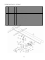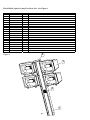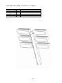
1
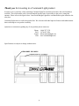
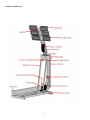
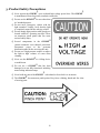
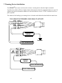
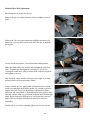
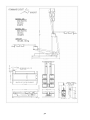
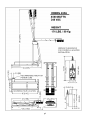
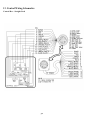
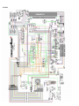
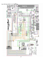
COMMAND LIGHT P.O. BOX 87 LOVELAND, CO 80539 PHONE: 1-800-797-7974 FAX: 1-970-667-4296 WEB: www.commandlight.com Serial Numbers: KL4901 and higher This document supersedes all previous documents. Effective Wednesday, January 04, 2006 1 Please take the time to read this manual before installing or operating the light. Save this guide for future reference. CONTENTS 1. BREAKAGE OR DAMAGE DURING SHIPMENT .......................................................................................................................4 1. BREAKAGE OR DAMAGE DURING SHIPMENT .......................................................................................................................5 2. GENERAL DESCRIPTION AND SPECIFICATIONS...................................................................................................................6 FEATURE IDENTIFICATION .....................................................................................................................................................................7 3. PRODUCT SAFETY PRECAUTIONS .............................................................................................................................................8 4. OPERATION .......................................................................................................................................................................................9 RAISING THE LIGHT FROM THE NESTED POSITION ...................................................................................................................................9 RETURNING THE LIGHT TO THE NESTED POSITION ..................................................................................................................................9 AUTO-PARK SEQUENCE .........................................................................................................................................................................9 5. INSTALLATION...............................................................................................................................................................................10 INSTALLATION KIT ..............................................................................................................................................................................10 TOOLS REQUIRED ................................................................................................................................................................................10 LOCATION REQUIREMENTS ..................................................................................................................................................................11 Recessed installations.....................................................................................................................................................................11 MOUNTING ..........................................................................................................................................................................................12 CONTROL BOX HOLSTER MOUNTING ..................................................................................................................................................12 6. ELECTRICAL WIRING ..................................................................................................................................................................13 120 VAC WIRING DIAGRAM ...............................................................................................................................................................14 240 VAC WIRING DIAGRAM ...............................................................................................................................................................14 220 VAC EUROPEAN ...........................................................................................................................................................................15 220 VAC / 12 VDC EUROPEAN ...........................................................................................................................................................15 7. WARNING DEVICE INSTALLATION .........................................................................................................................................16 8. MAINTENANCE...............................................................................................................................................................................17 LAMP REPLACEMENT ...........................................................................................................................................................................17 KL435 / KL450 ...............................................................................................................................................................................17 KL470MH.......................................................................................................................................................................................17 KL475/490......................................................................................................................................................................................18 KL495A ..........................................................................................................................................................................................18 CENTER SWITCH CAM ADJUSTMENT ...................................................................................................................................................19 ROTATION DRIVE BELT ADJUSTMENT .................................................................................................................................................20 ROTATION DRIVE BELT REPLACEMENT ...............................................................................................................................................21 9. POWER FAILURE ...........................................................................................................................................................................24 RETRACT THE LOWER STAGE FIRST. .....................................................................................................................................................24 RETRACT THE UPPER STAGE.................................................................................................................................................................25 10. TROUBLESHOOTING ..................................................................................................................................................................26 GENERAL .............................................................................................................................................................................................26 AUTOPARK MALFUNCTION ..................................................................................................................................................................27 SENSOR SWITCH TROUBLESHOOTING ..................................................................................................................................................28 11. TECHNICAL SPECIFICATIONS.................................................................................................................................................29 KL435 / KL450 ...................................................................................................................................................................................29 KL470MH...........................................................................................................................................................................................31 KL475/490 ..........................................................................................................................................................................................33 KL495A ..............................................................................................................................................................................................35 2 12. PARTS LISTS ..................................................................................................................................................................................37 PARTS LIST (KL450 STANDARD ASSEMBLY) - SEE FIGURE 1 ..............................................................................................................37 RELAY BOX PARTS – SEE FIGURE 2 .....................................................................................................................................................41 CONTROLLER PARTS – SEE FIGURE 3...................................................................................................................................................43 HOLSTER PARTS – SEE FIGURE 4 .........................................................................................................................................................44 BACKLIGHT OPTION PARTS LIST – SEE FIGURE 5 ................................................................................................................................45 METAL HALIDE, OPTION, LAMP TREE PARTS LIST – SEE FIGURE 6 .....................................................................................................46 METAL HALIDE, OPTION, TRANSFORMER COMPARTMENT PARTS LIST – SEE FIGURE 7 ......................................................................47 DESCRIPTION...................................................................................................................................................................................47 AERIAL, OPTION, LAMP TREE PARTS LIST – SEE FIGURE 8..................................................................................................................48 KL475/490, OPTION, LAMP TREE PARTS LIST – SEE FIGURE 8............................................................................................................49 13. CONTROL WIRING SCHEMATICS...........................................................................................................................................50 CONTROL BOX – STRAIGHT CORD .......................................................................................................................................................50 CONTROL BOX – COILED CORD ...........................................................................................................................................................51 KL450 .................................................................................................................................................................................................52 KL470MH...........................................................................................................................................................................................53 KL490 .................................................................................................................................................................................................54 EURO 220 VOLT .................................................................................................................................................................................55 EURO 220 VOLT / 12VDC....................................................................................................................................................................56 14. LIMITED WARRANTY.................................................................................................................................................................57 3 Thank you for investing in a Command Light product. In order to serve you better, when contacting Command Light for assistance please have the serial number(s) available. The serial number can be located stamped into the frame in proximity to the power connection entrance. Please refer to the figure below. Later model Knight Lights have an identification plate affixed to the relay box. Command Light strives to refine the product line. We welcome individual input on features and enhancements that would improve our product versatility. Questions or comments regarding any of our products please contact us. Phone: FAX: Email: Web: 1-800-797-7974 1-970-667-4296 [email protected] www.commandlight.com Specifications are subject to change without notice. 4 1. Breakage or Damage During Shipment The transportation company is fully responsible for all shipping damage and will resolve problems promptly if you handle it correctly. Please read these instructions carefully. Examine the contents of all shipping cases. If you find any damage, call your transportation agent at once and have them make a description on the freight or express bill describing the damage and the number of pieces. Then write us and we will send you the original bill of lading. Get a claim form from the express or truck company. Fill the claim form out. Attach the claim form to the original bill of lading together with a copy of our invoice. Attach a memo on which you show the value of the damaged goods. Mail or hand these papers to your local transportation agent. They will process your claim with reasonable promptness. Please note, we cannot and will not enter claims for damages. If we filed claim here, it would be sent to your local freight agent for verification and investigation. This time can be saved by you filing the claim directly. Every consignee is on the ground floor, in contact with the local agent who inspects the damaged goods, and thus, each claim can be given individual attention. Since our goods are packed to comply with the regulations of all railroad, truck, and express companies, we cannot allow deduction from any invoice because of any damage, however, be sure to file your claim promptly. Our goods are sold F.O.B. factory. We take receipt from the transportation company certifying that the goods were delivered to them in good order and our responsibility ceases. It is seldom that any breakage or damage occurs in any of our shipments and in no case will the customer be out any expense if they follow the above instructions. Be sure to keep all damaged goods subject to examination of the truck or express company inspector, who may call on you some time later. These damaged goods, of course, will belong to them, and they will inform you what to do with them. If you dispose of these damaged goods, your claim may not be paid. 5 2. General Description and Specifications The COMMAND LIGHT KNIGHT V2 is designed to provide high-intensity emergency scene lighting with quick precision. As with any electromechanical device, take precautionary steps to assure safe operation. 2 Never operate the KNIGHT near overhead power lines. Power for the 120/240 VAC circuitry is provided by the emergency vehicle generator. All mechanical actuation power is designed to be powered by the internal 12 VDC power supply. The umbilical corded control unit is powered via 12 VDC eliminating hazardous voltage levels within the hand held control box. EURO specification models incorporate an additional step down transformer for single line 220VAC operation. 2 The KNIGHT is manufactured to provide years of service with a minimum of maintenance. There are several lighting options available for the KNIGHT Model # KL435 KL450 KL470MH KL475 KL490 KL495A Description 6 x 350 watts 6 x 500 watts 4 x 175 watts 6 x 750 watts 6 x 900 watts 3 x 1500 watts 2 Power Requirements 2KW, 120 or 240 VAC 4KW, 120 or 240 VAC 2KW, 120 or 240 VAC 4.5KW, 240 VAC 5.6KW, 240 VAC 4.5KW, 240 VAC Replacement lamps are available from lighting dealers or direct from COMMAND LIGHT. Model 435 bulbs are 350 watt FCM/H1R-350T3/4 Model 450 bulbs are 500 watt, Q500T3/CL Model 470MH bulbs are 175 watt Sylvania M175/U/MED/ED17 G4479-0 or equivalent Model 475 bulbs are 750 watt Q750T3/CL Model 490 bulbs are 900 watt Q900T3/CL Model 495 bulbs are 1500 watt Q1500T3/CL Metal Halide Precautions WARNING: RISK OF ULTRAVIOLET RADIATION EXPOSURE! The Knight Light Model KL470MH is equipped with METAL HALIDE lamps. Metal Halide lamps are constructed of an outer glass bulb with an internal arc-tube made of quartz. Metal Halide arc-tubes operate at high pressure (up to 50 p.s.i.) and at very high temperatures and can unexpectedly rupture due to internal causes such as a ballast failure or misapplication. An arc-tube rupture can burst and shatter the outer glass bulb resulting in the discharge of glass fragments and extremely hot quartz particles (as high as 1832° F, 1000° C). These lamps can cause serious skin burn and eye inflammation from short wave ultraviolet radiation if the outer envelope of the lamp is broken or punctured. Do not use where people will remain for more than a few minutes unless adequate shielding or other safety precautions are used. 6 Feature Identification 7 3. Product Safety Precautions 2 2 [ Never operate the KNIGHT near overhead high voltage power lines. The KNIGHT is manufactured from electrically conductive materials. 2 [ Do not use the KNIGHT for uses other than its’ intended purpose. [ Do not move emergency vehicle with the light extended. Visually verify that the light is completely nested before moving vehicle. [ Do not change light position while people are located within its’ operating envelope. There are numerous pinch points that can cause serious bodily injury. 2 [ Several components in the KNIGHT contain automatic reset thermal protection. Disconnect power at the generator distribution panel before servicing the unit. [ Do not use a high-pressure washer or subject the light to high volumes of water when cleaning. 2 [ Never use the KNIGHT as a lifting device or mobile arm. 2 [ Do not use a KNIGHT that has been damaged or is not fully functional, including non-working indicator lamps. 2 [ Never hold any part of the KNIGHT with a hand or foot while it is in motion. 2 [ The KNIGHT has numerous pinch points. Keep loose clothing, hands and feet clear of moving parts. 8 4. Operation Raising the light from the nested position Using the control box, raise the lower or upper stage. You may also activate both stages simultaneously. Control switches are of momentary action style and must be held in the “on” position to actuate the stages. 2 The KNIGHT has an override system that precludes rotation of the upper stage until the lower stage has elevated ≈10” from the nested position. When the lower stage is below 10” a mercury switch controls the following: Upper stage is prevented from rotating All lights are turned off, including strobe light if equipped, regardless of light switch positions. Prevents the upper stage from moving down if upper stage is not centered. 2 If the supply from the generator is marginal, position the KNIGHT before turning on lights. Returning the light to the nested position 2 The KNIGHT is equipped with an auto park function as a standard feature. The green button on the control box initiates the auto-park sequence. Once initiated the “STOP” red indicator button is illuminated. Pressing the “STOP” button will cancel the auto-park sequence. Auto-park Sequence Press green button labeled AUTOPARK once. It does not need to be held in position. The auto-park sequence begins: 1. 2. 3. 4. 5. 6. 7. 8. 9. Emergency STOP red light is illuminated. Lamps are extinguished. Upper stage begins rotation clockwise to the center position. Center switch cam on spindle contacts the center switch. Green center indicator lamp is illuminated. Once upper stage is centered, rotation stops, lower stage begins retracting. Down limit plunger on midplate contacts plastic strike pad on frame engaging down limit switch. After lower stage has fully retracted, upper stage begins retracting. Nest contact bolt contacts nest switch (protective rubber cover) on relay box. Upon upper stage retracting fully, red emergency stop light turns off. 9 5. Installation 2 The KNIGHT must be installed by a designated installation facility by qualified personnel only. All safety precautions must be thoroughly understood before installation. Please consult the factory for additional installation information assistance. The screws for the cover are located in a parts bag inside the installation kit box. Installation Kit Included with the COMMAND LIGHT is an installation kit. Verify that the contents of the kit includes the following items: 50 feet of 10GA-4 Conductor power cable (1) Pre-wired HOLSTER BOX w/cover and 50 feet of 20 conductor cable (1) Control Box (1) Small hardware parts bag with: (4) mounting spacers (4) 5/16-18 X 2 ½” bolts (4) 5/16-18 nylon lock nuts (4) 5/16” flat washers (4) large diameter flat washers (2) ¼-20 X 5/8” pan head Phillips machine screws (12) ¼” flat washers (6) ¼-20 nylon lock nuts (4) ¼ -20 x 1 pan head Phillips machine screw (1) PVC wire grommet (2) ¼-20 x 1 socket head cap screw (1) 90 degree ½” sealing connector with nut (1) 90 degree ¾” sealing connector with nut Tools Required Lifting device (crane, forklift, block and tackle, etc.) Sling for lifting Drill 17 ” 21 ” /64 , /64 drill bits Hole saws for metal with a 7/8”, 1-1/8”, 1-1/4” diameter capacity Phillips head screwdrivers, #1 and #2 7 ” /16 and 1/2” combination wrenches and / or ratchet and 7/16” and 1/2” sockets 8” adjustable wrench Wire stripper or razor blade knife Solder-less wire connector crimp tool Silicone based gasket sealer, RTV™ recommended 2 The KNIGHT weighs between 136 – 174 pounds depending upon the model. Use mechanical assistance to lift the light into installation position such as a forklift or crane. Use a sling to grasp the light. Use the provided fender washers inside the mounting surface to distribute the weight load evenly. 10 When routing the connecting electrical wires take care to avoid sharp bends, hot components or other hazards to the wire. 2 The KNIGHT is not designed to be operated in a raised position while the vehicle is in motion. The 2 KNIGHT includes warning circuit wiring to enable a warning device, letting the vehicle operator know 2 when the KNIGHT is not in the nested (travel) position. Location Requirements 2 The KNIGHT can be mounted on any location that is KL435/KL450 KL470MH KL475/490 KL495A 47” x 23” 47” x 27” 58” x 32” 56” x 23” The surface should be flat or have only a slight crown. Recessed installations KL435 – KL450 KL470MH KL475/490 KL495A Allow for a minimum proper operation. Allow for a minimum proper operation. Allow for a minimum proper operation. Allow for a minimum proper operation. of 54” x 24” and a maximum of 10” deep to allow for of 54” x 30” and a maximum of 10” deep to allow for of 58” x 32” and a maximum of 10” deep to allow for of 58” x 24” and a maximum of 10” deep to allow for Four mounting bolt holes are required. Additional holes may be drilled in the frame ends if necessary to clear obstructions. Access hole for the power cord cabling should be in close proximity to the entrance box on the light. The control box should be mounted in an area shielded from the weather. Allow a minimum of 10” clearance above the control box mounting location to permit easy removal of the hand controller. 11 Mounting Place the provided spacers in the location of the light mounting holes. The spacers may be modified to conform to the contour of the mounting location. Remove any obstructions below the mounting surface such as headliners. Attach any necessary lifting attachments to the unit. The center of gravity (balance point) is slightly behind the lower bank of lights. 2 Slowly lift the KNIGHT and check for balanced lifting. Lower and make any necessary adjustments to the lift points. 2 Lift and place the KNIGHT into position above the spacers. Before placing the full weight of the unit on the spacers, align spacers with the holes in the end frame. Drill 21/64” holes in the mounting surface using the end frame holes as a template. Fasten the light using the provided hardware. To assure a weather tight installation apply a thin bead of silicone based gasket sealer to the base of the spacer and under side of bolt head. Remove any lifting straps and devices from the light. Locate and drill the wire feed holes. Control Box Holster Mounting Using the holster box as a template, mark hole locations. Drill 17 /64” mounting holes. Drill any holes required to route the control wire from the control box 2 holster to the KNIGHT unit. Mount holster box with provided hardware. 12 6. Electrical Wiring 2 Run the control wire from the control box to the KNIGHT . 2 Run the power wire from the breaker box or generator to the KNIGHT . A 40 Amp breaker is 2 recommended for all models of KNIGHT . 2 Make the control connections in the KNIGHT entrance box. Light is pre-wired to connect to 120 VAC for those lights that support 120 VAC use and can be connected for 240 VAC by removal of factory jumper. Model KL495A is wired for 240 VAC only. Drill a 1¼” diameter hole to provide access for routing of power and control wires through vehicle. A PVC grommet is provided to provide for a weatherproof installation. Use a silicone based sealant under the grommet to assure a weatherproof installation. 13 120 VAC Wiring Diagram 240 VAC Wiring Diagram If 240 VAC operation is desired, remove the jumper wire between the red and black leads. NOTE: The load on the (2) power legs will not be equally balanced. The RED lead powers the lamps and will carry ≈33% more load. The BLACK lead supplies voltage for rotation and actuation. 14 220 VAC European Verify that there is sufficient overhead room available and test operation of the light. 220 VAC / 12 VDC European Verify that there is sufficient overhead room available and test operation of the light. 15 7. Warning Device Installation 2 The KNIGHT nest sensor can be used to activate a warning device when the light is extended. Typically, the vehicle will have a light or buzzer that actuates when the compartment doors are open. To connect such a device determine whether it is activated when it receives 12 VDC or when it receives a path to ground. The connector for hooking up a warning device is located in the holster box that holds the control unit. FOR A DEVICE THAT REQUIRES 12VDC SIGNAL TO ACTIVATE RED BLACK YELLOW ORANGE WARNING DEVICE GROUND +12VDC FROM VEHICLE FOR A DEVICE THAT REQUIRES GROUND TO ACTIVATE RED BLACK GROUND YELLOW ORANGE WARNING DEVICE +12VDC FROM VEHICLE +12VDC FROM VEHICLE 16 8. Maintenance Lamp Replacement WARNING: NEVER remove any lamp from it’s socket while power supply is engaged! Allow sufficient time for the lamps to cool. The surrounding metal lamp housings can cause serious burns. Tools required: Clean oil-free cloth Cleaning alcohol Protective gloves Position lamp tree so lamps are readily accessible. This is usually with the lower stage in the retracted position and the upper stage extended to 90˚. 2 High voltages can be present inside lamp housings. Disconnect the power supply from the KNIGHT . The glass capsules of lamps that have been in service tend to be brittle, handle them with caution. KL435 / KL450 Grasp the lamp lens bezel firmly, release the latch that holds the lamp bezel in place. Use caution, The lamp bezel and lens may fall if not properly grasped. KL450 models after serial number KL4590 have a screw instead of a latch. Caution: be certain that the lamp is cool to the touch before handling. Do not touch the lamp directly. Use a clean oil-free towel to handle the lamp. The lamps operate at high temperatures. Handling the lamps directly leaves minute traces of skin oils that cause localized hot spots that can lead to early lamp failure. Lamp surfaces may be cleaned with alcohol. Latch the bezel making sure that the weather stripping is properly fitted. KL470MH Remove the (2) screws that hold the lamp bezel in place. Use caution, The lamp bezel and lens may fall if not properly grasped. Caution: be certain that the lamp is cool to the touch before handling. Do not touch the lamp directly. Use a clean oil-free towel to handle the lamp. The lamps operate at high temperatures and high pressure. Handling the lamps directly leaves minute traces of skin oils that cause localized hot spots that can lead to early lamp failure. Lamp surfaces may be cleaned with alcohol. Prior to installing the lamp in the fixture, check to be sure the lamp is of proper type and wattage. Screw the lamp securely into the socket, back the lamp out one to two turns, then screw the lamp back in, making sure it is secure. This properly seats the lamp in the socket. Refasten the bezel screws making sure that the weather stripping is properly fitted. 17 KL475/490 Remove the (4) screws that hold the lamp bezel in place. Use caution, The lamp bezel and lens may fall if not properly grasped. Caution: be certain that the lamp is cool to the touch before handling. Do not touch the lamp directly. Use a clean oil-free towel to handle the lamp. The lamps operate at high temperatures and high pressure. Handling the lamps directly leaves minute traces of skin oils that cause localized hot spots that can lead to early lamp failure. Lamp surfaces may be cleaned with alcohol. Prior to installing the lamp in the fixture, check to be sure the lamp is of proper type and wattage. Seat the lamp securely into the sockets. Refasten the bezel screws making sure that the weather stripping is properly fitted. KL495A Remove the (4) screws that hold the lamp bezel in place. Use caution, The lamp bezel and lens may need to be separated from the housing using a knife edged scraper or similar tool. Caution: be certain that the lamp is cool to the touch before handling. Do not touch the lamp directly. Use a clean oil-free towel to handle the lamp. The lamps operate at high temperatures. Handling the lamps directly leaves minute traces of skin oils that cause localized hot spots that can lead to early lamp failure. Lamp surfaces may be cleaned with alcohol. Remove lamp by grasping the left side and pushing the bulb towards the right hand socket. Once bulb end is clear of the left side socket rotate towards you to remove. When inserting bulb, insert bulb into the right side socket first. Refasten the bezel screws making sure that the weather stripping is properly fitted. 2 The KNIGHT is constructed with corrosion resistant aluminum and stainless steel fasteners. To further enhance corrosion resistance all exposed surfaces receive a powder coated paint finish. To assure years of trouble free service periodically clean all external surfaces with a mild detergent solution and a gentle spray of water. Do not use a high-pressure washer, which will force water into sensitive electric circuitry. Lamp lenses may be cleaned with any commercially available glass cleaner. Upper and lower stage actuators are sealed units and do not require adjustment or lubrication. 2 with a moisture displacing cleaner and soft bristle Periodic cleaning of all pivot points on the KNIGHT brush, without disassembly, to remove accumulated dirt and debris will minimize wear. 18 Center Switch Cam Adjustment 2 Symptom: KNIGHT lamp tree is not returning to center during AutoPark. Solution: Adjust center switch activating cam. Listed below are the steps to follow to adjust cam correctly. • • • • • • • • • • • • • Raise lamp tree to a 45 degree angle, raise lower section high enough to comfortably work on, and make sure you are above the set safety limit (i.e. Lights will turn on). Visually check to see that the centering cam on the rotation spindle is contacting the center switch. Rotate off center, then press the auto park button and let light tower proceed through sequence until the lamp tree is a couple inches above the nested position, hit emergency stop. Visually determine which side the lamp tree will be hitting the lift arm on. Raise lower section above safety limit and to comfortable working height. Loosen screw on center switch cam slightly. Tap center switch cam away from the side that the lamp tree is hitting on. Fully tighten the screw holding the center switch cam. Raise lamp tree to a 45 degree angle, rotate off center. Press the auto park button and let light tower proceed through sequence until the lamp tree is a couple inches above the nested position, hit emergency stop. If it looks like center is now adjusted properly, raise lamp tree to a 45 degree angle, and lower stage all the way up, press auto park and let it go through the entire sequence. If it is still hitting off center, repeat previous steps. If problems adjusting center still persist you may need to adjust the center switch bracket, or call Command Light at 1-800-797-7974 to order a new switch, part number 069-14222. Note: By making a mark next to the cam on the bottom of the spindle, this makes judging the distance much easier. Having the lamp tree at either extreme of fully up or down, will affect the degree of centering. The optimum is achieved by adjusting it at a 45 degree angle. If problems persist please call Command Light at 1-800-797-7974. 19 Rotation Drive Belt Adjustment Raise lamp tree to permit easy access. Remove the (6) screws that retain the 2-piece midplate cover in place. Remove the (4) screws that retains the midplate surround cover. Rotate the cover up and away from the main lift arm, around the pivot point Loosen, but do not remove, screws that retain rotation motor. Make sure both pulleys are parallel and in alignment with each other. To adjust any misalignment loosen the (2) set screws securing the small drive pulley to motor shaft. Adjust as required and tighten set screws. Belt should fit snugly, neither too loose nor too tight. Avoid any preload, which can cause premature failure. Using a suitable pry bar, apply gentle pressure between rotation motor case and sheet metal motor mount. Use caution to not over tighten drive belt. Drive belt should have a minimum of 2mm deflection and a maximum of 4mm midway between pulleys when adjusted with the lamp tree positioned as shown in the bottom right photo. Rotate lamp tree 180 degrees to verify that belt is not too tight. If belt is too tight, rotation motor noise level will rise noticeably. Replace all covers before returning light tower to active service. 20 Rotation Drive Belt Replacement Remove midplate covers as outlined previously. Raise lamp tree enough to provide easy access to the twist-lock connectors located above the actuator. Disconnect all connectors found. The number of connectors will vary depending on what options you model of light tower has. Loosen and remove (4) hex head bolts securing lamp tree. Slide lamp tree away from rotation platform. Lamp tree is a tight sliding fit. Do not use excessive force. If lamp tree does not slide with relative ease verify that you have disconnected all cable connections. 21 While supporting the actuator remove lamp tree mount arms. Use caution the actuator weighs approximately 13 pounds [6kg] and can cause injury if not supporting adequately. Mount arms are universal and can go on either side. Note position of lamp tree mount holes in photo at right for proper reassembly position Remove (4) E-ring retaining clips securing actuator lower pivot pin in place. It is recommended that new E-rings be used for reassembly. Support actuator and remove lower pivot pin. New belt can be installed without further disassembly. Place belt over rotation platform. Starting from one edge, begin sliding the belt past the circular dust shields. 22 Belt will take some effort to slide past the dust shield. Work it over the shield a little at a time. Once belt is past the shield, slide rotation motor towards the center of the motor mount. Begin guiding the belt over the drive pulley. To assist in getting belt over pulley you can activate the rotation switch on the hand controller to turn the motor. Follow previous procedure to adjust the belt tension. 23 9. Power Failure 2 The KNIGHT can be retracted manually if power to the unit is lost. If power loss is temporary, reestablishing power may be easier than manually retracting the light. 2 Disconnect all power sources from the KNIGHT . Retract the lower stage first. Slowly apply pressure to the rotation platform to manually rotate to the centered position. Trying to rotate the platform too quickly or with too much pressure can break the rotation motor shaft or cause the toothed drive belt to shear a tooth. The upper stage can be rotated in either direction. Generally, you need to rotate the platform in the direction that requires the least amount of travel in order to center the platform. Support the mid-plate assembly with temporary blocking to relieve the tension on the lower actuator pivot pins. Using a small flat blade screw driver, remove the retaining rings that secure the lower pivot pin in place. New retaining rings must be installed before returning light to service. Use a brass drift punch to remove the pivot pin from the extension end of the actuator. Avoid using a hardened steel punch which could peen the end of the shaft thus damaging the bore within the aluminum pivot blocks. Note the upper stage of the light weighs in excess of 100 pounds, use caution. Apply upward pressure on the main lift arm to remove support blocking then slowly lower the lift arm allowing the actuator shaft to extend past the lower pivot blocks. 24 Retract the upper stage. Support the lamp tree with temporary blocking to relieve the tension on the upper actuator pivot pins. Unfasten the twist lock connector for the upper actuator. The connector is located above and in front of the actuator. The actuator connector is the medium sized of the 3 connectors found there. Using a small flat blade screw driver remove the 4 e-clips securing the lower pin of the upper actuator. While supporting the lamp tree, lamp tree weighs between 27 – 46 pounds depending on configuration, use a brass drift to remove the pin. Lift up on lamp tree to remove support blocking. Rotate the actuator towards the front of the light. The upper stage will not be completely lowered but should provide ample clearance to transport the light. Cushion and secure the actuators and other components as necessary before transporting. 25 10. Troubleshooting General Problem Unit will not extend Upper stage will not rotate Lights will not illuminate. Lights will not turn off Rotation coasts after switch is released Unit will not nest Possible Cause No power to the unit Incorrect installation Lower stage not raised above 40mm Rotation motor in thermal overload. Rotation motor failure. Lower stage not raised above 40mm Circuit breaker tripped. No power to the unit. Lamp filament broken. Unit overheated Loose drive belt. Upper stage not centered Unit being operated on a slope >15 degrees Solution Check power input connections. Refer to installation instructions. Raise lower stage higher. Allow rotation motor to cool. Consult with factory. Raise lower stage higher. Check circuit breaker at power supply. Check power supply operation/output. Replace lamp. Turn off power allow unit to cool Consult with factory Raise lower stage > 10”. Center upper stage (green light illuminated) Lower upper stage to horizontal. Using a pole, hold unit level while lowering to nest position. 26 Autopark Malfunction Problem Autopark button must be held in to park unit Upper actuator and rotation start simultaneously Autopark stops after lamp tree has centered and lower actuator has retracted. Upper stage does not retract. Lamp tree comes down off center. Lamp tree continues to rotate. Possible Cause Improper or faulty ground Water in electronics Solution Check nest switch ground and operation. Centering cam out of adjustment. Light being operated on too severe an angle. Centering cam out of adjustment. Center switch defective Adjust center switch cam. Remove moisture from ground points and electronics. Do not use a pressure washer to clean unit. Stuck or broken nest Clean switch plunger surface of accumulated debris. switch Lubricate plunger with dry graphite. If problem persists replace switch. Nest engagement bolt not Lower bolt and / or raise switch adjustment. contacting switch fully. Realign bolt to switch. 12VDC power not Trace connections to red/green wire and verify present on red/green continuity to +12VDC using wiring schematic. For a control wire located in replacement wiring schematic please call Command holster box. Light 1-800-797-7974 Down limit switch stuck Clean and dry lubricate switch. Midplate plunger stuck. Clean plunger and apply an anti-seize compound. Down limit switch Replace switch. defective.. Nest switch stuck. Clean and dry lubricate switch. Rubber cover holding Replace rubber cover. nest switch down. Defective nest switch. Replace switch. Adjust center switch cam. Replace switch. 27 Sensor Switch Troubleshooting Description Rotation Limit Switch (item 106 on parts list) Nest Switch (Located inside relay box) Function Mercury switch. Provides ground for safety limit relays. Prevents operation of lamps and rotation when lower stage is below ≈ 12 inches. Normally closed. Provides ground for autopark sequence, red indicator lamp on controller and vehicle warning device. Down Limit Switch (item 49 on parts list) Normally closed. Provides ground for autopark sequence. Centering switch (item 25 on parts list) Normally open. Indicates to autopark upper stage is centered for nest. Provides ground for center indicator lamp on controller. 28 Problem Lamps will not illuminate, upper stage will not rotate. Solution Adjust angle of switch, replace if necessary. Upper stage will not retract during autopark. Warning device on vehicle does not deactivate. Light will rotate to center, lower stage retracts, upper stage remains extended. Inspect protective switch cover for damage. Adjust nest switch plunger (item 93 on parts list). Upper stage will not retract during autopark. Upper stage not centered. Check down limit plunger (item 47 on parts list) for freedom of movement. Adjust switch as necessary. Adjust switch mount and/or cam. Adjust drive belt tension. 11. Technical Specifications KL435 / KL450 Dimensions: Height(Depth) 11.375” 7’4” 10” Maximum Retracted Extended Recessed installation Length 47” 52” 54” Minimum Width 23” 23” 24” Minimum Weight: 136 pounds Wiring: 110 VAC Control wiring Relay protection: Lights Other electrical 10/4 SO cord 22/20 PVC Jacketed Cole-Hersey Cole-Hersey 3055 3055 Current Draw / Power Requirements: Max @ 110 VAC 500 Watt bulbs 350 Watt bulbs 50’ provided 50’ provided 40 40 Max @ 240 VAC 24 amps 17 amps 12 amps 9 amps Generator Requirement 4 kW minimum 2 kW minimum Motor Duty Cycle: (All motors thermally protected, specifications are to thermal relay trip): Lower stage Upper stage Rotation Motor Speed: Lower stage Upper stage Rotation Full Deployment Auto Park Operation Angle of vehicle Wind load Design maximum Maximum tested 1:3 (90 seconds maximum per 5 minute) 1:3 (90 seconds maximum per 5 minute) 5-6 Revolutions 0.5 inches per minute 0.5 inches per minute 3.25 RPM at lamp tree Lower and upper stages Rotate 180 degees and retract 15˚ maximum incline 65 mph 55 mph 29 10 seconds to full extension 12 seconds to full extension 15 seconds to full actuator extension 40 seconds from full extension 30 KL470MH Dimensions: Retracted Extended Recessed installation Height(Depth) 14.75” 7’4” 10” Maximum Length 47” 52” 54” Minimum Width 27” 27” 30” Minimum Weight: 160 pounds Wiring: 110 VAC Control wiring Relay protection: Lights Other electrical 10/4 SO cord 22/20 PVC Jacketed Cole-Hersey Cole-Hersey 3055 3055 Current Draw / Power Requirements: Max @ 110 VAC 175 Watt bulbs 50’ provided 50’ provided 40 40 Max @ 240 VAC 10 amps 7 amps Generator Requirement 2 kW minimum Motor Duty Cycle: (All motors thermally protected, specifications are to thermal relay trip): Lower stage Upper stage Rotation Motor Speed: Lower stage Upper stage Rotation Full Deployment Auto Park Operation Angle of vehicle Wind load Design maximum Maximum tested 1:3 (90 seconds maximum per 5 minute) 1:3 (90 seconds maximum per 5 minute) 5-6 Revolutions 0.5 inches per minute 0.5 inches per minute 3.25 RPM at lamp tree Lower and upper stages Rotate 180 degrees and retract 15˚ maximum incline 65 mph 55 mph 31 10 seconds to full extension 12 seconds to full extension 15 seconds to full actuator extension 40 seconds from full extension 32 KL475/490 Dimensions: Retracted Extended Recessed installation Height(Depth) 13.375” 7’4” 13” Maximum Length 54.75” 95.25” 58” Minimum Width 30” 30” 32” Minimum Weight: 174 pounds Wiring: 240 VAC Control wiring Relay protection: Lights Other electrical 10/4 SO cord 22/20 PVC Jacketed Cole-Hersey Cole-Hersey 3055 3055 Current Draw / Power Requirements: Max @ 240 VAC 750 Watt bulbs 900 Watt bulbs 50’ provided 50’ provided 19 amps 24 amps 40 40 Generator Requirement 4.5 kW minimum 6.5 kW minimum Motor Duty Cycle: (All motors thermally protected, specifications are to thermal relay trip): Lower stage Upper stage Rotation Motor Speed: Lower stage Upper stage Rotation Full Deployment Auto Park Operation Angle of vehicle Wind load Design maximum Maximum tested 1:3 (90 seconds maximum per 5 minute) 1:3 (90 seconds maximum per 5 minute) 5-6 Revolutions 0.5 inches per minute 0.5 inches per minute 3.25 RPM at lamp tree Lower and upper stages Rotate 180 degees and retract 15˚ maximum incline 65 mph 55 mph 33 10 seconds to full extension 12 seconds to full extension 15 seconds to full actuator extension 40 seconds from full extension 34 KL495A Dimensions: Retracted Extended Recessed installation Height(Depth) 11.375” 7’4” 10” Maximum Length 54.75” 95.25” 58” Minimum Width 23” 23” 24” Minimum Weight: 174 pounds Wiring: 240 VAC Control wiring Relay protection: Lights Other electrical 10/4 SO cord 22/20 PVC Jacketed Cole-Hersey Cole-Hersey 3055 3055 Current Draw / Power Requirements: Max @ 240 VAC 1500 Watt bulbs 50’ provided 50’ provided 8 amps 40 40 Generator Requirement 4.5 kW minimum Motor Duty Cycle: (All motors thermally protected, specifications are to thermal relay trip): Lower stage Upper stage Rotation Motor Speed: Lower stage Upper stage Rotation Full Deployment Auto Park Operation Angle of vehicle Wind load Design maximum Maximum tested 1:3 (90 seconds maximum per 5 minute) 1:3 (90 seconds maximum per 5 minute) 5-6 Revolutions 0.5 inches per minute 0.5 inches per minute 3.25 RPM at lamp tree Lower and upper stages Rotate 180 degees and retract 15˚ maximum incline 65 mph 55 mph 35 10 seconds to full extension 12 seconds to full extension 15 seconds to full actuator extension 40 seconds from full extension 36 12. Parts Lists Parts List (KL450 Standard Assembly) - See Figure 1 ITEM 1 2 3 4 5 6 7 8 9 10 11 12 13 14 15 16 17 18 19 20 21 22 23 24 25 26 27 28 29 30 31 32 33 34 35 36 37 38 39 40 41 42 QTY 1 4 4 1 2 12 1 1 1 2 1 1 1 1 4 4 2 1 1 1 1 1 2 1 1 2 2 2 1 2 2 2 1 2 1 4 1 4 1 1 2 2 PART NO. 075-01000A 034-11042 034-11053 075-06500 034-13033 069-15336 075-06020 075-01700A 075-06010 075-01600 069-15355 075-06050 075-06080 075-06060 034-11042 034-11053 075-01300 075-02001A 075-03400 075-03410 034-11030 034-11001 069-15335 069-15334 069-14222 034-13288 034-14283 034-10899 075-03500 034-10939 034-10949 034-10947 075-03300 034-10942 065-12966 034-11017 065-12860 034-11028 075-06030 075-03530 024-10524 034-10941 DESCRIPTION FRAME, MAIN BOLT, HEX HEAD, 5/16-18 X 1, SS WASHER, SPLIT RING LOCK, 5/16, SS PLATE, DOWN LIMIT STRIKE SCREW, HEX HEAD, ¼-20 X 7/8, SS E-CLIP SHAFT, UPPER STABILIZER PIVOT ARM, STABILIZER SHAFT, LOWER STABILIZER PIVOT BLOCK, LOWER ACTUATOR PIVOT ACTUATOR, LOWER SHAFT, UPPER, LOWER ACTUATOR SHAFT, LOWER, LOWER ACTUATOR SHAFT, LOWER, LIFT ARM PIVOT SCREW, HEX HEAD, 5/16-18 X 1, SS WASHER, SPLIT RING LOCK, 5/16 CAP, MAIN FRAME ARM, MAIN LIFT SPINDLE CAM, SWITCH WASHER, INTERNAL LOCK, ¼, SS SCREW, PANHEAD MS, ¼-20 X ½, SS RACE , NEEDLE BEARING BEARING, NEEDLE ROLLER SWITCH, CENTER SCREW, PANHEAD PHILLIPS, 4-40 X ¾ ,SS WASHERS, INTERNAL LOCK, #4, SS NUT, 4-40, SS PLATE, CENTER SWITCH SCREW, PANHEAD, 8-32 X ½ , SS WASHER, INTERNAL LOCK, #8, SS WASHER FLAT, #8, SS BLOCK, SLIP RING SCREW, PH, 8-32 X 1, SS PIN, SLIP RING SCREW, HEX HEAD, ¼-20 X 1, SS CLAMP, WIRE LOOM, #10 WASHER, SPLIT RING LOCK, ¼, SS SHAFT, UPPER, LIFT ARM PIVOT STOP, MIDPLATE BUMPER, RUBBER, 0638-MW SCREW, PH, 8-32 X ¾ , SS 37 43 44 45 46 47 48 49 50 51 52 53 54 55 56 57 58 59 60 61 62 63 64 65 66 67 68 69 70 71 72 73 74 75 76 77 78 79 80 81 2 2 2 2 1 1 1 2 2 4 4 2 1 1 1 1 1 1 1 1 1 10 1 1 1 1 4 1 1 4 4 4 4 1 1 1 1 2 1 034-10951 034-11017 034-11028 075-03000 075-03520 075-03510 069-15360 034-11001 034-11028 034-11017 034-11028 075-03100 075-03200 069-15333 065-12817 069-14152 069-15361 075-04310 075-04300 075-03605 075-03610 034-10961 069-14153 065-13833 069-14151 075-06400 034-11033 075-03620 075-03600 034-13039 034-10977 034-10977 034-11004 069-15356 075-06070 075-04100A 024-10527 034-13059 034-10850 82 83 84 85 86 87 1 1 1 1 1 1 2 1 032-10857 032-10861 075-06120 075-06060 075-05000 075-06060 075-06110 075-05300A NUT, LOCKING, #8, SS SCREW, HEX HEAD, ¼-20 X 1, SS WASHER, SPLIT RING LOCK, ¼, SS BLOCK, PIVOT, MAIN LIFT UPPER PLUNGER, DOWN LIMIT PLATE, DOWN LIMIT SWITCH SWITCH, DOWN LIMIT SCREW, PH MS, ¼-20 X ½ , SS WASHER, SPLIT RING LOCK, ¼, SS SCREW, HEX HEAD, ¼-20 X 1, SS WASHER, SPLIT RING LOCK, ¼, SS BLOCK, MIDPLATE PIVOT PLATE, MIDPLATE BEARING, SPINDLE, 6308-2NSE SLIP RING PULLEY, ROTATION PIN, ROTATION DRIVE DISK, LOWER, ROTATION DISK, UPPER, ROTATION COVER, REAR, MIDPLATE COVER, SURROUND, MIDPLATE SCREW, PH MS, 10-24 X 3/8, SS BELT, DRIVE MOTOR, ROTATION PULLEY, DRIVE KEY, DRIVE PULLEY NUT, NYLOCK, ¼-20, SS MOUNT, ROTATION MOTOR COVER, FRONT, MIDPLATE SCREW, PH MS, 10-32 X ¾ , SS WASHER, FLAT, #10, SS WASHER, INTERNAL LOCK, #10, SS SCREW, PH MS, ¼-20 X 1, SS ACTUATOR, UPPER SHAFT, LOWER, UPPER ACTUATOR PLATFORM, ROTATION PAD, RUBBER SCREW, FH MS, 8-32 X 5/8 SS BOLT, HEX HEAD, ¾-10 X 3, KL4268 – KL4629 Starting with Serial Number: KL4630 BOLT, HEX HEAD, ¾-10 X 7 NUT, HEX, ¾-10 GUIDE, LOWER, LAMP TREE WIRE SHAFT, LAMP TREE PIVOT ARM, LAMP TREE SHAFT, UPPER, UPPER ACTUATOR GUIDE, UPPER, LAMP TREE WIRE TREE, LAMP 38 88 89 90 91 92 93 94 95 NI NI 96 97 98 99 100 101 102 103 NI 104 105 106 107 108 109 110 NI NI 4 4 12 12 12 1 2 6 6 6 1 1 2 2 1 2 2 1 1 1 1 1 3 3 1 3 1 1 034-11041 034-11053 034-11033 034-11017 034-11112 034-11020 034-11033 069-15332 065-12850 065-14024 075-90000 075-90001 034-11032 034-11028 075-05400 034-10961 034-10997 065-12867X 065-13824 075-90002 075-90003 049-12293 065-12861 034-10997 034-11030 034-11033 075-06300 069-14106 SCREW, HEX HEAD, 5/16-18 X ¾ , SS WASHER, SPLIT RING LOCK, 5/16, SS NUT, NYLOCK, ¼-20, SS SCREW, PH MS, ¼-20 X 7/8 , SS NUT, ¼-20, JAM, SS BOLT, HEX HEAD, ¼-20 X 1¾ , SS NUT, NYLOCK, ¼-20, SS LAMP BULB, 500 WATT BULB, 350 WATT HARNESS, LAMP HARNESS, STROBE NUT, HEX, ¼-20, SS WASHER, SPLIT RING LOCK, ¼, SS BRACKET, NEST SCREW, PH MS, 10-24 X 3/8 , SS SCREW, FLAT HEAD, ¼-20 X 1, SS STROBE, SPECIFY COLOR, PRE-WIRED BULB, STROBE HARNESS, AC FEED HARNESS, DC FEED SWITCH, SAFE LIMIT CLAMP, WIRE LOOM, #8 SCREW, PHP MS, ¼-20 X 1, SS WASHERS, INTERNAL LOCK, ¼ , SS NUT, NYLOCK, ¼-20, SS GROMMET, POWER CABLES DECAL, KNIGHT LIGHT 39 Figure 1 40 Relay Box Parts – See Figure 2 QTY 1 1 1 1 2 1 3 16 16 1 1 1 1 2 2 10 2 12 6 2 2 4 15 20 20 20 1 1 1 1 1 1 PART NO. 069-15360 069-15351 069-15347 069-15350 065-13530 065-13529 065-14020 065-13730 065-13729 065-14780 065-12852 065-12854 065-14576 034-10919 034-10924 034-10939 034-13060 034-10951 034-10962 034-10966 034-10968 034-10978 034-10981 034-11002 034-11028 034-11032 054-12315 065-12828 065-12827 065-12826 075-07002 065-15339 DESCRIPTION SWITCH, NEST SOCKET, 2 POSITION SOCKET, 7 POSITION SOCKET, 10 POSITION BREAKER, 12V 40A BREAKER, 24V 20A RELAY, AC LAMPS SOCKET, BOSCH RELAY, BOSCH LIGHT,LOOKUP,BLACK SEALCON, ½, STRAIGHT SEALCON, ¾”, STRAIGHT TRANSFORMER, 12V 15A, POWER SUPPLY SCREW, 6-32 X ¾,PH PHIL, SS NUT, 6-32, NYLOCK, SS SCREW, 8-32 X ½,PH PHIL, SS SCREW,8-32 X ¾,PH PHIL,SS NUT,8-32,NYLOCK,SS SCREW,10-24 X ½,PH PHIL,SS SCREW,10-24 X ¾,PH PHIL,SS SCREW, 10-24 X 1,PH PHIL, SS WASHER, #10, INTERNAL LOCK,SS NUT,10-24,NYLOCK,SS SCREW, ¼-20 X 5/8,PH PHIL, SS WASHER, ¼, LOCK, SS NUT, ¼-20, SS BLOCK, TERMINAL,5 POSITION BLOCK, TERMINAL, 16 POSITION BLOCK, TERMINAL, 12 POSITION BLOCK, TERMINAL, 4 POSITION PLATE, COMPONENT MOUNT TRANSFORMER, 230VAC IN, 115VAC OUT, EURO ONLY 41 Figure 2 42 Controller Parts – See Figure 3 ITEM C1 C2 C3 C4 C5 C6 C7 C8 C9 PART NO. 065-12833 075-00722 065-13959 065-12844 065-12844 065-12846 065-12845 065-12845 065-12845 065-12842 065-12843 065-12855 065-12856 QTY 1 1 1 3 1 7 1 1 1 1 1 1 1 10’ DESCRIPTION PLASTIBOX P5-11333-E SWITCH MOUNT PLATE LABEL, CONTROL PANEL SWITCH SPST, LIGHT BANK SWITCH SPST, STROBE BOOT, SWITCH COVER SWITCH DPMT, ROTATION SWITCH DPMT, UP STAGE SWITCH DPMT, LOW STAGE INDICATOR LAMP, RED INDICATOR LAMP, GREEN STRAIN RELIEF ½” SEALCON NUT COILED UMBILICAL CORD Figure 3 43 Holster Parts – See Figure 4 H1 H2 H3 H4 H5 H6 H7 H8 H9 H10 H11 H12 H13 H14 065-12921 034-10909 075-00712 065-14139 065-14138 075-00711 065-14089 065-14093 065-14088 065-14091 065-14092 065-14090 065-13729 034-10939 1 4 1 1 1 1 1 1 1 1 1 1 1 1 LABEL, CAUTION #6 X 3/8” SM SCREW HOLSTER, COVER LABEL, STOP LABEL, AUTOPARK HOLSTER BOX OPERATOR, RED BULB #756 12VDC #E22D120 FULL VOLT UNIT #E22B1 CONTACT BLK NC #E22B2 CONTACT BLK NO #E22PB3 GREEN OPERATOR RELAY #0-332-207-107 8-32 X ½” PH PHILIPS CS SS H15 H16 H17 H18 H19 H20 H21 H22 H23 H24 H25 H26 H27 Figure 4 44 065-13730 034-10951 034-10902 034-14283 065-12826 034-13288 065-12835 034-10909 065-12834 065-12838 065-12868 065-12856 065-12852 1 1 2 2 1 2 1 4 1 1 1 1 1 RELAY MODULE 8-32 LOCKNUT SS 4-40 HEX NUT #4 INTERNAL LOCK WASH TERM STRIP 4 POLE 4-40 X ¾” PH PHILIPS SS AMP CONNECTOR MALE #6 X 3/8” SM SCREW AMP CONNECTOR FEMALE AMP STRAIN RELIEF GROMMET #763 ½” NUT, SEALCON ½” SEALCON, STRAIGHT Backlight Option Parts List – See Figure 5 ITEM 1 2 3 4 5 6 7 8 9 10 11 12 13 14 15 16 17 NI NI PART NO 075-12090W 075-12060W 069-14154 069-14155 034-10990 065-13834 075-12080 075-12050 075-12030 075-12020 075-12040 034-11033 075-12010 034-11029 034-11028 034-11016 069-15360 069-15359 065-14183 QTY 1 2 2 1 4 1 1 2 1 1 1 2 1 2 2 4 2 2 1 DESCRIPTION TREE, BACKLIGHT, KV2, WELDMENT MOUNT, LAMP, BACKLIGHT, KV2 PULLEY, 48 GR, 3MM P, .3125 ID BELT, 11 GR, 3MM P, 333MM NUT, 10-32, HEX, SS GEAR MOTOR, BACKLIGHT, 2L005 SHAFT, BACKLIGHT, KNIGHT V2 KEY, SHAFT, BACKLIGHT TRIGGER, SWITCH, BACKLIGHT BLOCK, SHAFT, BACKLIGHT SPACER, SHAFT, BACKLIGHT NUT, ¼-20, HEX, NYLOCK, SS MOUNT, MOTOR, BACKLIGHT, KV2 WASHER, FLAT, ¼, SS WASHER, SPLIT LOCK, ¼, SS BOLT, ¼-20 X ¾ , HEX, SS SWITCH, LIMIT, BACKLIGHT BOOT, SWITCH, GRAY RELAY, LATCHING, AUTOPARK Figure 5 45 Metal Halide, Option, Lamp Tree Parts List – See Figure 6 ITEM 1 2 3 PART NO 075-08000W 075-08001 034-10973 075-08100A DN-T10EB DN-T10RED DN-T10BLK DN-T10YEL DN-T10BLU DN-T10GRY DN-T10WHT DN-T10RL 065-14033 051-15408 4 Figure 6 034-11017 034-11029 034-11033 075-08002 QTY 1 1 8 1 2 1 1 1 1 1 1 1 4 8 8 4 8 16 8 1 DESCRIPTION TREE, METAL HALIDE, KV2, WELDMENT TREE, COVER, METAL HALIDE SCREW, 10-24 X ½, PHP, SS DIN, BLOCK, ASSEMBLY DIN, END BLOCK DIN, CONNECTOR, SINGLE, RED DIN, CONNECTOR, SINGLE, BLACK DIN, CONNECTOR, SINGLE, YELLOW DIN, CONNECTOR, SINGLE, BLUE DIN, CONNECTOR, SINGLE, GREY DIN, CONNECTOR, SINGLE, WHITE DIN, RAIL, 4 INCH FIXTURE, LAMP, METAL HALIDE, 175W SEALCON, STRAIGHT, 3/8 SEALCON, NUT, 3/8 CABLE, 18/2, SJEOOW, 24 INCH BOLT, ¼-20 X 1, HEX, SS WASHER, FLAT, ¼, SS NUT, NYLOCK, ¼-20, SS BRACKET, NEST, METAL HALIDE 4 3 2 1 46 Metal Halide, Option, Transformer Compartment Parts List – See Figure 7 ITEM PART NO 1 075-08200 075-08300 034-10938 2 034-10978 034-10989 072-15273 3 056-12436 034-10973 034-10981 075-08100A DN-T10EB DN-T10RED DN-T10BLK DN-T10YEL DN-T10BLU DN-T10GRY DN-T10WHT DN-T10RL 034-10938 034-10951 4 QTY DESCRIPTION 1 1 12 4 16 36 32 16 4 4 4 4 1 2 1 1 1 1 1 1 1 2 2 BOX, TRANSFORMER, METAL HALIDE LID, TRANSFORMER BOX, METAL HALIDE SCREW, 8-32 X 3/8, PHP, SS TRANSFORMER, 175 W, METAL HALIDE SCREW, 10-24 X 3-1/2, PHP, SS WASHER, INTERNAL LOCK, #10, SS NUT, 10-24, SS SPACER, BRASS, ¾ CAPACITOR, 175 W, METAL HALIDE CLAMP, #26, SCREW, 10-24 X ½, PHP, SS NUT, NYLOCK, 10-24, SS DIN, BLOCK, ASSEMBLY DIN, END BLOCK DIN, CONNECTOR, SINGLE, RED DIN, CONNECTOR, SINGLE, BLACK DIN, CONNECTOR, SINGLE, YELLOW DIN, CONNECTOR, SINGLE, BLUE DIN, CONNECTOR, SINGLE, GREY DIN, CONNECTOR, SINGLE, WHITE DIN, RAIL, 4 INCH SCREW, 8-32 X 3/8, PHP, SS NUT, NYLOCK, 8-32, SS 3 4 Figure 7 2 1 47 Aerial, Option, Lamp Tree Parts List – See Figure 8 ITEM 1 2 3 4 5 6 7 8 PART NO 075-08000W 065-14031 075-90004 034-11017 034-11016 034-11029 034-11033 034-11016 075-08002 QTY 1 3 1 6 2 14 4 2 1 DESCRIPTION TREE, AERIAL, KV2, WELDMENT FIXTURE, LAMP, FRC, 1000W HARNESS, LAMP, AERIAL, KV2 BOLT, ¼-20 X 1, HEX, SS BOLT, ¼-20 X 3/4, HEX, SS WASHER, FLAT, ¼, SS NUT, NYLOCK, ¼-20, SS BOLT, ¼-20 X 3/4, HEX, SS BRACKET, NEST, AERIAL Figure 8 48 KL475/490, Option, Lamp Tree Parts List – See Figure 8 PART NO 075-08000HS 065-14036 075-90000 065-12852 075-08002 QTY 1 3 1 6 1 DESCRIPTION TREE, HSL, KV2, WELDMENT FIXTURE, LAMP, HS, Specify Wattage HARNESS, LAMP, KV2 SEALING CONNECTOR BRACKET, NEST 49 13. Control Wiring Schematics Control Box – Straight Cord 50 Control Box – Coiled Cord 51 KL450 52 KL470MH 53 KL490 54 EURO 220 Volt 55 Euro 220 Volt / 12VDC 56 14. Limited Warranty Five Year COMMAND LIGHT warrants that the equipment is free from defects in materials and workmanship when used and operated for a period of five years. The responsibility of COMMAND LIGHT under this limited warranty is limited to the repair and replacement of any parts found defective. Parts are returned to COMMAND LIGHT at 1303 East 11th Street, Loveland, Colorado 80537 with transportation charges prepaid (C.O.D. shipments will not be accepted). Prior to returning defective parts to COMMAND LIGHT, the original purchaser shall make a claim in writing to COMMAND LIGHT at the above address indicating the model number, serial number and type of defect. No parts or equipment will be received by COMMAND LIGHT for repair or replacement under this warranty without specific written authority from COMMAND LIGHT in advance. Any parts damaged by improper installation, overloading, abuse or accident of any type or cause are not covered by this warranty. All equipment manufactured by us is tested before leaving our plant, and is shipped in good working order and condition. We therefore extend to the original purchasers the following Limited Warranty for the period of five years from the original date of purchase: 1. This warranty does not apply to defects caused by accident, misuse, neglect, or wear and tear, nor can we be held responsible for incidental and consequential expense and loss, nor does this warranty apply to equipment where alterations have been executed without our knowledge or consent. These conditions are readily discernable when the equipment is returned to us for inspection. 2. On all component parts not manufactured by COMMAND LIGHT, their warranty is to the extent that the manufacturer of such component warrants them to COMMAND LIGHT, if at all. Look in your local business telephone directory for the nearest repair station for the brand of parts you have or write to us for the address. 3. If equipment received has been damaged in transit, a claim should be made against the carrier within three days, as we assume no responsibility for such damage. 4. Any service other than our Authorized Service voids this warranty. 5. This warranty is in lieu of and is intended to exclude all other warranties, express or implied, oral or written, including any warranties of MERCHANTIBILITY or FITNESS for a particular purpose. 57