1
STP 11-25V13-SM-TG
HEADQUARTERS
DEPARTMENT OF THE ARMY
Soldier's Manual
and Trainer's Guide
MOS 25V
COMBAT DOCUMENTATION/
PRODUCTION SPECIALIST
SKILL LEVELS 1, 2, and 3
DISTRIBUTION RESTRICTION: Approved for public release; distribution is unlimited.
STP 11-25V13-SM-TG
*
SOLDIER TRAINING
PUBLICATION
No. 11-25V13-SM-TG
HEADQUARTERS
DEPARTMENT OF THE ARMY
Washington, DC, 28 February 2002
SOLDIER'S MANUAL AND TRAINER'S GUIDE
MOS 25V
COMBAT DOCUMENTATION/PRODUCTION SPECIALIST
Skill Levels 1, 2, and 3
TABLE OF CONTENTS
PAGE
Table of Contents ...................................................................................................................... i
PREFACE .................................................................................................................................................... iii
Chapter 1. Introduction........................................................................................................................... 1-1
Chapter 2. Trainer's Guide (TG)............................................................................................................. 2-1
Chapter 3. MOS/Skill Level Tasks ......................................................................................................... 3-1
Skill Level 1
113-578-1012
113-578-3062
113-578-3063
113-578-3029
113-578-3064
113-578-3065
Subject Area 1: STILL DOCUMENTATION
Perform Copy Photography...................................................................................... 3-1
Mix Photographic Chemistry .................................................................................... 3-3
Process Photographic Film ...................................................................................... 3-4
Produce Black-and-White Projection Prints ............................................................. 3-6
Produce Color Projection Prints ............................................................................... 3-8
Operate Automatic Printer Processor.....................................................................3-10
Subject Area 2: TELEVISION PRODUCTION
113-575-2003 Operate Teleprompter/Cue Cards..........................................................................3-11
113-577-2038 Produce an Electronic Message for Television Presentation.................................3-13
*
DISTRIBUTION RESTRICTION: Approved for public release; distribution is unlimited.
*This publication supersedes STP 11-25V13-SM-TG, 3 January 1995.
i
STP 11-25V13-SM-TG
113-577-1063
113-635-2001
113-577-2039
113-577-2040
113-577-2041
113-578-1040
113-578-4009
113-578-4010
113-631-6016
113-578-4011
113-578-4001
Subject Area 3: COMBAT CAMERA OPERATIONS
Prepare a Script/Shooting Outline..........................................................................3-14
Operate a Video Camera System During a Combat Mission.................................3-16
Document Combat Audio for a Presentation..........................................................3-17
Edit Combat Audio/Video for Production................................................................3-19
Non-Linear Editing for Combat Audio/Video Production ........................................3-21
Capture a Still Image on Film During a Combat Mission .......................................3-22
Capture a Digital Image During a Combat Mission ................................................3-24
Acquire a Digital Image in Support of a Combat Mission.......................................3-26
Write a Caption.......................................................................................................3-27
Edit a Digital Image in Support of a Combat Mission.............................................3-28
Produce a Digital Print in Support of a Combat Mission ........................................3-30
Skill Level 2
Subject Area 3: COMBAT CAMERA OPERATIONS
113-578-8001 Setup a Digital Image System ................................................................................3-32
113-577-4050 Transmit a Video Information Presentation ............................................................3-33
113-635-4001 Electronically Transmit a Image in Support of a Combat Mission..........................3-35
Skill Level 3
113-577-2037
113-631-6012
113-635-6001
113-631-6013
113-577-7001
113-578-5031
Subject Area 3: COMBAT CAMERA OPERATIONS
Direct a Television Production................................................................................3-36
Process Visual Information Work Order .................................................................3-38
Coordinate a Combat Camera Mission ..................................................................3-39
Write a Master Caption...........................................................................................3-41
Supervise Transmission of a Video Information Presentation ...............................3-42
Perform Quality Control on Photographic Processor Chemistry............................3-43
APPENDIX A - ELECTRONIC IMAGING COURSE ................................................................................ A-1
APPENDIX B - PHOTOGRAPHIC STANDARDS CHECKLIST .............................................................. B-1
APPENDIX C - STILL PHOTOGRAPHY EDITING AND PROCESSING SYSTEM (SPEPS) ................ C-1
APPENDIX D - CARE OF PHOTOGRAPHIC EQUIPMENT IN CLIMATIC EXTREMES........................ D-1
APPENDIX E - COMBAT CAMERA .........................................................................................................E-1
APPENDIX F - STUDIO OPERATIONS....................................................................................................F-1
APPENDIX G - PRODUCTION SWITCHER ............................................................................................ G-1
APPENDIX H - VIDEO.............................................................................................................................. H-1
APPENDIX I - BASIC LIGHTING ............................................................................................................... I-1
APPENDIX J - SPECIAL KINDS OF PHOTOGRAPHY AND USE OF FILTERS.................................... J-1
APPENDIX K - AUDIO ............................................................................................................................. K-1
APPENDIX L - TRAINING AIDS (FORMS)...............................................................................................L-1
Glossary ...................................................................................................................................... Glossary-1
References.............................................................................................................................. References-1
ii
STP 11-25V13-SM-TG
PREFACE
This publication is for skill levels (SLs) 1, 2, and 3 soldiers holding military occupational
specialty (MOS) 25V and for trainers and first-line supervisors. It contains standardized training
objectives, in the form of task summaries, to train and evaluate soldiers on critical tasks that
support unit missions. Trainers and first-line supervisor should ensure soldiers holding MOS
25V SLs 1, 2, and 3 have access to this publication through their assigned work areas, unit
learning center, unit libraries, and the General Dennis J. Reimer Training and Doctrine Digital
Library website (http://155.217.58.58/atdls.htm).
This manual applies to both Active and Reserve Component soldiers.
The proponent for this publication is the Signal School. Users of this publication are
encouraged to report errors, recommend changes, and submit comments on its improvement.
Comments should be keyed to the specific page, paragraph, and line of the text in which the
change is recommended. Reasons will be provided for each comment to ensure understanding
and complete evaluation. Comments should be made on DA Form 2028 directly to Commander,
US Army Signal Center and Fort Gordon, ATTN: ATZH-DTM-I, Fort Gordon, Georgia 309055074.
Unless this manual states otherwise, masculine pronouns do not refer
exclusively to men.
iii
STP 11-25V13-SM-TG
CHAPTER 1
Introduction
1-1.
GENERAL
a. This manual identifies the individual MOS training requirement for soldiers in MOS
25V. Commanders, trainers, and soldiers should use it to plan, conduct, and evaluate individual
training in units. This manual is the primary MOS reference to support the self-development
and training of every soldier.
b. Use this manual with the Soldier’s Manual of Common Tasks (STP 21-1-SMCT and
STP 21-24-SMCT), Army training and evaluation programs (ARTEPs), and FM 25-101, BattleFocused Training, to establish effective training plans and programs that integrate soldier,
leader, and collective tasks.
1-2.
TASK SUMMARIES
a. Task summaries outline the wartime performance of each critical task in the soldier’s
manual (SM). They provide the soldier and trainer with the information necessary to prepare,
conduct, and evaluate critical tasks soldier proficiency on training. As a minimum, task
summaries include information you must know and the skills that you must perform to standards
for each task. The format for the task summaries included in this SM is as follows:
(1) Task Title. The task title identifies the action to be performed.
(2) Task Number. A 10-digit number identifies each task or skill. Include this task number,
along with the task title, in any correspondence relating to the task. To determine which tasks
are testable at each skill level, refer to Chapter 2, Part 2, Critical Tasks. The first numbers of
the last four of each task DO NOT indicate the skill levels testable for that particular task.
(3) Conditions. The task conditions identify all the equipment, tools, references, job aids,
and supporting personnel that the soldier needs to perform the task in wartime. This section
identifies any environmental conditions that can alter task performance, such as visibility,
temperature, and wind. This section also identifies any specific cues or events (a chemical
attack or identification of a threat vehicle) that trigger task performance.
(4) Standards. The task standards describe how well and to what level you must perform
a task under wartime conditions. Standards are typically described in terms of accuracy,
completeness, and speed.
(5) Training and Evaluation. This section may contain all or part of the following: training
information outline (performance steps in Automated Systems Approach to Training (ASAT)),
evaluation preparation, and evaluation guide (performance measures in ASAT). The training
information outline/performance steps include detailed training information. The evaluation
preparation subsection indicates necessary modification to task performance in order to train
and evaluate a task that cannot be trained to the wartime standard under wartime conditions. It
may also include special training and evaluation preparation instructions to accommodate these
modifications and any instructions that should be given to the soldier before evaluation. The
evaluation guide/performance measures identify the specific actions that the soldier must do to
1-1
STP 11-25V13-SM-TG
successfully complete the task. These actions are listed in a Pass/Fail format for easy
evaluation. Each task contains a feedback statement (Evaluation Guidance in ASAT) that
indicates the requirements (for the number of performance measures passed) for receiving a
GO on the evaluations.
(6) References. This section identifies references that provide more detailed and thorough
explanations of task performance requirements than those given in the task summary
description.
b. Additionally, some task summaries include safety statements and notes. Safety
statements (danger, warning, and caution) alert user to the possibility of immediate death,
personal injury, or damage to equipment. Notes provide a small, extra supportive explanation of
hint relative to the performance measures.
1-3.
SOLDIER’S RESPONSIBILITIES
Each soldier is responsible for performing individual tasks, which the first-line
supervisor identifies based on the unit’s mission essential task list (METL). The soldier
must perform the task to the standards listed in the SM. If a soldier has a question about
how to do a task, or which tasks in the manual he must perform, it is the soldier’s
responsibility to ask the first-line supervisor for clarification. The first-line supervisor knows
how to perform each task, or can direct the soldier to the appropriate training materials.
1-4.
NCO SELF-DEVELOPMENT AND THE SOLDIER’S MANUAL
a. Self-development is one of the key components of the leader development program. It
is a planned progressive and sequential program followed by leaders, to enhance and sustain
their military competencies. It consists of individual study, research, professional reading,
practice, and self-assessment. Under the self-development concept the NCO, as an Army
professional, has the responsibility to remain current in all phases of the MOS. The SM is the
primary source for the NCO to use in maintaining MOS proficiency.
b. Another important training resource for NCO self-development is Army
Correspondence Course Program (ACCP). Soldiers should refer to DA Pamphlet 350-59, The
Army Correspondence Course Program Catalog, for information on enrolling in this program
and a list of courses, or write to: Army Institute for Professional Development, US Army
Training Support Center, ATTN: ATIC-IPS, Newport News, VA 23628-0001.
c. Unit learning centers are valuable resources for planning self-development programs.
They can help access enlisted career maps, training support products, and extension training
materials, such as field manuals (FMs), technical manuals (TMs), and training extension course
(TEC) lessons. It is the soldier’s responsibility to use these materials to maintain performance.
1-2
STP 11-25V13-SM-TG
1-5.
TRAINING SUPPORT
This manual includes the following appendixes and information that provide additional
training support information.
(1) Appendix A. Electronic Imaging Course.
(2) Appendix B. Photographic Standards Checklist.
(3) Appendix C. Still Photography Editing and Processing System (SPEPS).
(4) Appendix D. Care of Photographic Equipment in Climatic Extremes.
(5) Appendix E. Combat Camera.
(6) Appendix F. Studio Operations.
(7) Appendix G. Production Switcher.
(8) Appendix H. Video.
(9) Appendix I. Basic Lighting.
(10) Appendix J. Special Kinds of Photography and Use of Filters.
(11) Appendix K. Audio.
(12) Appendix L. Training Aids (Forms).
(13) Glossary. The Glossary is a single comprehensive list of acronyms, abbreviations,
definitions, and letter symbols.
(14) References. This section contains two lists of references, required and related, which
support training of all tasks in this SM. Required references are listed in the conditions
statement and are required for the soldier to do the task. Related references are materials that
provide ore detailed information and more thorough explanation of task performance.
1-6.
OPTIONAL INFORMATION
a. All soldiers and NCOs in MOS 25V should be acquainted with skill and training
progression for the Combat Documentation/Production Specialist, training problems unique to
MOS 25V, and the career management field (CMF) sturucture.
b. The career progression chart for MOS 25V is shown in Figure 1-1. It shows the entrylevel soldier and the path he must follow to SL5. Ther are no decision points for the 25V soldier.
1-3
STP 11-25V13-SM-TG
00Z50
SGM
Skill Level 5
25Z50
MSG/1SG/SGM
Skill Level 5
US Army Sergeants Major Academy
(USASMA)
25Z40
SFC
Skill Level 4
Visual Information Operations Chief
25V30
SSG
Skill Level 3
Senior Combat Documentation/Production NCO
Advanced Noncommissioned Officer Course
(BNCOC)
25V20
SGT
Skill Level 2
Combat Documentation/Production Specialist
Basic Noncommissioned Officer Course
(BNCOC)
25V10
PVT/PFC/SPC
Skill Level 1
Trainee
Combat Documentation/Production Specialist
Primary Leadership Development Course (PLDC)
Advanced Individual Training (AIT)
Basic Training (BT)
Figure 1-1. Skill and Training Progression, MOS 25V
1-4
STP 11-25V13-SM-TG
c. The tasks in this soldier’s manual are common in commercial industry. In some cases,
a specific piece of equipment or soltware is identified. However, any commercial equipment or
software available can be used following the manufacturer’s operating instructions manual as
long as the equipment or software used meets job standards. Unlike most table(s) of
organization and equipment (TOE) unit, visual information units may not be equipped with the
same model or type of equipment or software. It is necessary that the soldier have an
opportunity to train by using the same type of equipment or software referenced in this soldier’s
manual. Keep in mind that the self-development test will be based on specific information
contained in this manual. Many tasks in the combat documentation production specialist field
must be learned through on-the-job training. Some of the latest techniques strongly
recommended that all soldiers have access to commercial technical production literature
available at post libraries or through local purchase.
d. Comments or questions on material in this manual may be directed to Commander, US
Army Signal School Detachment, Student Company, ATTN: ATZH-SDT-T, Chief Training
Development, Building 8611 6th Armored Cavalry Road, Fort George G. Meade, MD 207555155, DSN 923-5805/5802 or commercial (301) 677-5805/5802.
1-5
STP 11-25V13-SM-TG
CHAPTER 2
Trainer's Guide (TG)
2-1.
GENERAL
a. The TG identifies the essential components of a unit training plan for individual training.
Units have different training needs and requirements based on differences in environment,
location, equipment, dispersion (actual manning of graphic shops), and similar factors.
Therefore, the TG is a guide used for conducting unit training and not as a rigid standard.
b.
MOS.
The TG provides information necessary for planning training requirements for this
(1)
Identifies subject areas in which to train soldiers.
(2)
Identifies the critical tasks for each subject area.
(3)
Specifies where soldiers are trained.
(4)
Recommends how often to train each task to sustain proficiency.
(5)
Recommends a strategy for training soldiers to perform higher level tasks.
2-2.
BATTLE FOCUSED TRAINING
As described in FM 25-100, Training the Force, and FM 25-101, Battle Focused Training,
the commander must first define the Mission Essential Task List (METL) as the basis for unit
training. Unit leaders use the METL to identify the collective, leader, and soldier tasks that
support accomplishment of the METL. Unit leaders then assess the status of training and lay out
the training objective and the plan for accomplishing needed training. After preparing the longand short-range plans, leaders then execute and evaluate training. Finally, the unit’s training
preparedness is reassessed and the training management cycle begins again. This process
ensures the unit has identified what is important for the wartime mission, the training focus is
applied to the necessary training, and training meets established objectives and standards.
2-3.
RELATIONSHIP OF SOLDIER TRAINING PUBLICATIONS (STP) TO
BATTLE FOCUSED TRAINING
a. They two key components of enlisted STP are the TG and SM. The TG and SM give
leaders important information to help in the battle focused training process. The TG relates
soldier and leader tasks in the MOS and SL to duty positions and equipment. It provides
information on where the task is trained, how often training should occur to sustain proficiency,
and who in the unit should be trained. As leaders go through the assessment and planning
stages, they should use the TG as a important tool in identifying what needs to be trained.
b. The execution and evaluation of soldier and leader training should rely on the
Armywide training objective and standards in the SM task summaries. The task summaries
ensure that soldiers in any unit or location have the same definition of task performance, and
that trainers evaluate the soldiers to the same standard.
2-1
STP 11-25V13-SM-TG
c.
The following diagram shows the relationship between battle-focused training and the
use of the TG and SM. The left-hand side of the diagram (taken from FM 25-101) shows the
soldier training process, while the right side of the diagram shows how the STP supports each
step of this process.
2-2
BATTLE FOCUS PROCESS
STP SUPPORT PROCESS
SELECTS SUPPORTING
SOLDIER TASKS
USES TG TO RELATE
TASKS TO METL
CONDUCTS TRAINING
ASSESSMENT
USES TG TO DEFINE WHAT
SOLDIER TASKS TO ASSESS
DETERMINES TRAINING
OBJECTIVES
USES TG TO SET
OBJECTIVES
DETERMINES STRATEGY
AND PLANS FOR TRAINING
USES TG TO RELATE
SOLDIER TASKS
TO STRATEGY
CONDUCTS PRE-EXECUTION
CHECKS
USES SM TO DETERMINE
TRAINING PREPARATION
EXECUTES TRAINING
AND CONDUCTS
AFTER-ACTION REVIEW
USES SM TASK SUMMARY
AS SOURCE FOR
TASK PERFORMANCE
EVALUATES TRAINING
AGAINST ESTABLISHED
STANDARDS
USES SM TASK SUMMARY
AS STANDARD FOR
EVALUATION
STP 11-25V13-SM-TG
2-4.
TRAINER’S RESPONSIBILITIES
Training soldier and leader tasks to standard and relating this training to collective missionessential tasks is the NCO trainer’s responsibility. Trainers use the steps below to plan and
evaluate training.
(1) Identify soldier and leader training requirements. The NCO determines which
tasks soldiers need to train on using the commander’s training strategy. The unit’s METL and
ARTEP and MOS Training Plan (MTP) in the TG are sources for helping the training define the
individual training needed.
(2) Plan the training. Training for specific tasks can usually be integrated or conducted
concurrently with other training or during “slack periods.” The unit’s ARTEP can assist in
identifying soldier and leader tasks that can be trained and evaluated concurrently with
collective task training and evaluation.
(3) Gather the training references and materials. The SM task summary list all
references which can assist the trainer in preparing for the training of that task.
(4) Determine risk assessment and identify safety concerns. Analyze the risk involved
in training a specific task under the current conditions at the time of scheduled training. Ensure
that your training preparation takes into account those cautions, warnings, and dangers
associated with each task.
(5) Train each soldier. Show the soldier how the task is done to standard, and explain
step-by-step how to do the task. Give each soldier one chance to do the task step-by-step.
(6) Emphasize training at mission-oriented protection posture (MOPP) level 4.
Soldiers may have difficulty performing even the very simple tasks in a nuclear/chemical
environment. The combat effectiveness of the soldier and the unit can degrade quickly when
trying to perform in MOPP4. Practice is the best way to improve and to ensure performance.
(7) Check each soldier. Evaluate how well each soldier performs the tasks in this
manual. Conduct these evaluations during individual training sessions or while evaluating
soldier proficiency during the conduct of unit collective tasks. Use the information in the MTP as
a guide to determine how often to train the soldier in each task to ensure that soldiers sustain
proficiency.
(8) Record the results. The leader book referred to in FM 25-101, Appendix B, is used to
record task performance and gives the leader total flexibility on the method of recording training.
The trainer may use DA Forms 5164-R (Hands-On Evaluation) and 5165-R (Field Expedient
Squad Book) as part of the leader book. The forms are optional and locally reproducible. STP
21-24-SMCT contains a copy of the forms and instructions for their use.
(9) Retrain and evaluate. Work with each soldier until he can perform the task to specific
SM standards.
2-3
STP 11-25V13-SM-TG
2-5.
EVALUATION GUIDE
An evaluation guide exists for each task summary in the SM. Each evaluation guide
contains one or more performance measures that identify what the trainer needs to observe to
score a soldier’s performance. Each step is clearly identified by a P (pass) and F (fail), located
under the results column on each evaluation guide. Some tasks involve a process that the
trainer must evaluate an “end product” resulting from doing the task. The following are some
general points about using the evaluation guide to evaluate soldiers.
(1) Review the guide to become familiar with the information on which the soldier will be
scored.
(2) Ensure that the necessary safety equipment and clothing needed for proper
performance of the job are on hand at the training site.
(3) Prepare the test site according to the conditions section of the task summary. Some
tasks contain special evaluation preparation instructions. These instructions tell the trainer what
modifications must be made to the job conditions to evaluate the task. Reestablish the test site
to the original requirements after evaluating each soldier to ensure that conditions are the same
for each soldier.
(4) Advise each soldier of the information in the brief soldier section of the task summary
before evaluating.
(5) Score each soldier according to the performance measures and feedback section in
the evaluation guide.
(6)
2-6.
a.
Record the date and task performance (GO or NO-GO) in the leader book.
TRAINING TIPS FOR THE TRAINER
Prepare yourself.
(1) Get training guidance from your chain of command on when to train, which soldiers to
train, availability of resources, and a training site.
(2) Get the training objective (tasks, conditions, and standards) from the task summary in
this manual.
(3) Ensure you can do the task. Review the task summary and references in the reference
section. Practice doing the task or, if necessary, have someone train you on the task.
(4) Choose a training method. Some tasks provide recommended training methods in the
feedback section of the task summary.
(5) Prepare training outline consisting of informal notes on what you want to cover during
your training session.
(6)
2-4
Practice your training presentation.
STP 11-25V13-SM-TG
b.
Prepare the resources.
(1)
Obtain the required resources identified in the conditions statement for each task.
(2)
Gather equipment and ensure it is operational.
(3)
Coordinate the use of training aids and devices.
(4) Prepare the training site according to the conditions statement and evaluation
preparation section of the task summary, as appropriate.
c.
Prepare the soldiers.
(1) Tell the soldier what task to do and how well it must be done. Refer to the standard
statement and evaluation preparation section for each task, as appropriate.
(2)
Caution soldiers about safety, environment, and security.
(3) Provide any necessary training on basic skills that soldiers must have before they can
be trained on the task.
(4) Pretest each soldier to determine who needs training in what areas by having the
soldier perform the task. Use DA Form 5164-R and the evaluation guide in each task summary
to make this determination.
d.
Train the soldiers who failed the pretest.
(1) Demonstrate how to do the task or the specific performance steps to those soldiers
who could not perform to SM standards. Have soldiers study the appropriate materials.
(2)
Have soldiers practice the task until they can perform it to SM standards.
(3)
Evaluate each soldier using the evaluation guide.
(4) Provide feedback to those soldiers who fail to perform it to SM standards, and have
them continue to practice until they can perform to SM standards.
e.
2-7.
Record results in the leader book.
MOS TRAINING PLAN
One of the key components of the TG is the MOS Training Plan (MTP). The MTP has two
parts to assist the commander in preparing a unit training plan that satisfies integration, crosstrain, train-up, and sustainment training requirements for soldiers in this MOS.
(1) Part one of the MTP shows the relationship of an MOS SL between duty position and
critical tasks. The critical tasks are grouped by task commonality into subject areas.
(a) Section I lists subject area numbers and titles used through out the MTP. The subject
areas define the training requirements for each duty position within an MOS, and relate duty
positions to subject areas and cross-training and train-up/merger requirements.
2-5
STP 11-25V13-SM-TG
•
Duty position column. This column contains the MOS duty positions, by skill level,
which have different training requirements.
•
Subject area column. This column lists by subject area number, the subject areas in
which the soldier must be proficient for that duty position.
•
Cross-train column. This column lists the recommended duty position for which
soldiers should be cross-trained.
•
Train-up/merger column. This column lists the corresponding duty position for the next
higher SL or MOS the soldier will merge into upon promotion.
(b) Section II identifies the total training requirements in terms of subject areas listed in
Section I for each duty position in an MOS.
(2) Part two lists by subject areas, the critical tasks to be trained in an MOS, task number,
task title, location, sustainment training frequency, and training SL.
•
Subject area column. This column lists the subject area number and title in the same
order as in the MTP, Part One, Section I.
•
Task number column. This column lists the task numbers for all tasks included in the
subject area.
•
Task title column. This column lists the task title.
•
Training location column. This column identifies the training location where the task is
first trained to STP standards. If the task is first trained to standard in the unit, the word
“Unit” will be in this column. If the task is first trained to standard in the training base, it
will identify the resident course where the task was taught. Figure 2-1 contains a list of
training locations and their brevity codes.
AIT
UNIT
Advanced Individual Training
Trained in the Unit
Figure 2-1. Training Locations
2-6
STP 11-25V13-SM-TG
•
Sustainment training frequency column. This column indicates the recommended
frequency at which tasks should be trained to ensure soldier maintains task proficiency.
Figure 2-2 identifies the frequency codes to use in this column.
BA
AN
SA
QT
MO
BW
WK
-
Biannually
Annually
Semiannually
Quarterly
Monthly
Bi-weekly
Weekly
Figure 2-2. Sustainment Training Frequency Codes
•
Sustainment training SL column. This column lists the SLs of the MOS for which
soldiers must receive sustainment training to ensure they maintain proficiency to SM
standards.
MOS TRAINING PLAN
MOS 25V
PART ONE
Skill Level 1
SECTION I: SUBJECT AREA CODES
Skill Level 2
Skill Level 3
1. Still Documentation
2. Television Production
3. Combat Camera Operations
3. Combat Camera Operations
3. Combat Camera Operations
MOS TRAINING PLAN
MOS 25V
PART ONE
SL
SL1
SECTION II: DUTY POSITION TRAINING REQUIREMENTS
DUTY POSITION
CROSS TRAIN TRAIN-UP/ MERGER
SUBJECT
AREA
NA
25V20 Combat
1-3
Combat Documentation/
Documentation/Production
Production Specialiat
Specialist
SL2
Combat Documentation/
Production Specialist
1-3
NA
25V30 Senior Combat
Documentation/Production
NCO
SL3
Senior Combat
Documentation/Production
NCO
1-3
NA
25Z40 Visual Information
Operations Chief
2-7
STP 11-25V13-SM-TG
MOS TRAINING PLAN
25V13
CRITICAL TASKS
Subject Area
Task Number
Title
Training
Location
Sust
Tng
Freq
Sust
Tng
SL
Skill Level 1
1. STILL
DOCUMENTATION
2. TELEVISION
PRODUCTION
3. COMBAT
CAMERA
OPERATIONS
2-8
113-578-1012
Perform Copy Photography
AIT
QT
1-3
113-578-3029
Produce Black and White Projection
Prints
AIT
QT
1-3
113-578-3062
Mix Photographic Chemistry
AIT
QT
1-3
113-578-3063
Process Photographic Film
AIT
QT
1-3
113-578-3064
Produce Color Projection Prints
AIT
QT
1-3
113-578-3065
Operate Automatic Printer Processor
AIT
QT
1-3
113-575-2003
Operate Teleprompter/Cue Cards
AIT
QT
1-3
113-577-2038
Produce an Electronic Message for
Television Presentation
AIT
QT
1-3
113-577-1063
Prepare a Script/Shooting Outline
AIT
QT
1-3
113-577-2039
Document Combat Audio for a
Presentation
AIT
QT
1-3
113-577-2040
Edit Combat Audio/Video for Production
AIT
QT
1-3
113-577-2041
Non-Linear Editing for Combat
Audio/Video Production
AIT
QT
1-3
113-578-1040
Capture a Still Image on Film During a
Combat Mission
AIT
QT
1-3
113-578-4001
Produce a Digital Print in Support of a
Combat Mission
AIT
QT
1-3
113-578-4009
Capture a Digital Image During a
Combat Mission
AIT
QT
1-3
113-578-4010
Acquire a Digital Image in Support of a
Combat Mission
AIT
QT
1-3
113-578-4011
Edit a Digital Image in Support of a
Combat Mission
AIT
QT
1-3
113-631-6016
Write a Caption
AIT
QT
1-3
STP 11-25V13-SM-TG
CRITICAL TASKS
Subject Area
3. COMBAT
CAMERA
OPERATIONS
(continued)
Task Number
113-635-2001
Title
Operate a Video Camera System
During a Combat Mission
Training
Location
Sust
Tng
Freq
Sust
Tng
SL
AIT
QT
1-3
Skill Level 2
3. COMBAT
CAMERA
OPERATIONS
(continued)
113-577-4050
Transmit a Video Information
Presentation
UNIT
QT
2-3
113-578-8001
Setup a Digital Image System
UNIT
QT
2-3
113-635-4001
Electronically Transmit a Image in
Support of a Combat Mission
UNIT
QT
2-3
Skill Level 3
3. COMBAT
CAMERA
OPERATIONS
(continued)
113-577-2037
Direct a Television Production
UNIT
QT
3
113-577-7001
Supervise Transmission of a Video
Information Presentation
UNIT
QT
3
113-578-5031
Perform Quality Control on
Photographic Processor Chemistry
UNIT
QT
3
113-631-6012
Process Visual Information Work Order
UNIT
QT
3
113-631-6013
Write a Master Caption
UNIT
QT
3
113-635-6001
Coordinate a Combat Camera Mission
UNIT
QT
3
2-9
STP 11-25V13-SM-TG
CHAPTER 3
MOS/Skill Level Tasks
Skill Level 1
Subject Area 1: STILL DOCUMENTATION
Perform Copy Photography
113-578-1012
Conditions: In a combat, field or garrison environment, given DA Form 3903, original media to be copied,
camera set, tripod or copy stand, light meter, film, lighting equipment, filter factor chart, and a
Photographic Standards Checklist.
Standards: Reproduction was in sharp focus with sufficient contrast and density to show all details of the
original and was in accordance with the Photographic Standards Checklist and DA Form 3903.
Performance Measures
GO
NO GO
1. Reviewed DA Form 3903 to determine requirements.
——
——
2. Selected camera.
a. Selected and installed lens.
b. If required, sat up tripod and mount camera.
c. If required, made swing and tilt adjustments.
——
——
3. Prepared copy material.
a. Selected copy subject.
b. If required, attached copy material vertically to flat surface.
c. If required, loaded film holder.
d. Withdrew the dark slide from film holder.
e. Swung the bottom flap out to open the bottom of the film holder.
f. Turned lights OFF.
g. Removed one sheet of unexposed cut film from film box.
h. Held the film by its edges so as not to leave fingerprints and so that the
emulsion (dull) side was up and the identification notches were in the lower
right hand corner and pushed film into holder.
i. Swung the bottom flap closed and held it down firmly.
j. Pushed the dark slide all the way into the cut film holder, with silver side out.
k. Turned the dark slide lock over the end of the dark slide, to prevent
accidental removal of the dark slide.
l. Replaced unused film in box and closed cover.
m. Turned lights ON.
——
——
4. Illuminated subject.
a. Arranged lamps to illuminate subject.
b. Adjusted lights to obtain 1:1 ratio (even lighting).
——
——
5. Obtained light reading using a photoelectric light meter.
a. Checked meter for zero and balance.
b. Took a reflected meter reading to obtain basic exposure.
——
——
6. Cropped and focused on copy material to obtain required negative for end product
according to DA Form 3903.
——
——
7. If required, calculated bellows extension factor (BEF).
——
——
3-1
STP 11-25V13-SM-TG
Performance Measures
a. Measured bellows extension (BE).
b. Divided lens focal length (FL) into BE .
c. Squared result to determine BEF.
d. Calculated BE x BEF = NE (new exposure).
GO
NO GO
8. Selected filters to alter rendition of colors recorded on black and white film.
a. Reviewed DA Form 3903 for filter requirements.
b. Selected filter.
(1) Removed transparent stain by using a filter the same color, only
slightly darker.
(2) Lightened a color by using a filter of the same color.
(3) Darkened a color by using a filter of the opposite color.
c. Referred to filter chart to find filter factor (FF).
d. Calculated BE x FF = NE.
——
——
9. Set corrected exposure (BE x BEF x FF = NE).
——
——
10. Exposed film.
——
——
11. Secured camera.
——
——
12. Processed film.
——
——
13. Evaluated film.
——
——
Evaluation Guidance: Score the soldier GO if all steps are passed. Score the soldier NO-GO if any
step is failed. If the soldier fails any steps, show what was done wrong and how to do it correctly. Have
the soldier practice until he can correctly perform the task.
References
Required
PHOTO STDS CHECKLIST
3-2
Related
APPENDIX B (25V)
SS0511
SS0512
TM 11-401-2
TM 11-6720-211-10
STP 11-25V13-SM-TG
Mix Photographic Chemistry
113-578-3062
Conditions: In a combat field or garrison environment, given photographic chemicals, manufacturer’s
instruction sheets, hot and cold running water, thermometer, tanks, mixer (automatic or manual),
graduate, storage bottles, labels, hydrometer, test strips or test roll of film, and cleaning supplies.
Standards: Chemistry was of proper quantity, fully dissolved, stored in proper containers, and passed
quality control tests in accordance with manufacturer's specifications.
Performance Measures
GO
NO GO
1. Gathered and cleaned all equipment.
——
——
2. Read manufacturer's instruction sheets.
——
——
3. Brought water to recommended temperature.
——
——
4. Filled mixer or mixing tank with amount of water recommended by manufacturer's
instruction sheets.
——
——
——
——
6. Added chemistry.
——
——
7. Topped off with water to obtain proper quantity.
——
——
8. Mixed completely as required by manufacturer's instruction sheets.
——
——
——
——
10. Stored in accordance with manufacturer's instruction sheets.
——
——
11. Labeled storage container.
——
——
12. Cleaned all equipment.
——
——
5. Conducted temperature check.
CAUTION: When mixing, pour chemicals slowly into water to avoid splashing. Avoid
breathing chemical dust or fumes. Always add acids to water. Also, follow all
manufacturers’ safety regulations.
9. Conducted quality control check.
a. Hydrometer.
b. Test strip.
NOTE: If no quality control equipment is available, process a test roll of film ensuring
accurate detail in highlight and shadow areas.
Evaluation Guidance: Score the soldier GO if all steps are passed. Score the soldier NO-GO if any
step is failed. If the soldier fails any steps, show what was done wrong and how to do it correctly. Have
the soldier practice until he can correctly perform the task.
References
Required
MFG INSTRUCTION SHEETS
Related
KODAK PHOTO LAB INDEX
3-3
STP 11-25V13-SM-TG
Process Photographic Film
113-578-3063
Conditions: In a combat, field or garrison environment, given a DA Form 3903, an operational lab
containing premixed chemicals, storage containers, tanks and reels, temperature controlled sink/water,
graduate, timer, thermometer, exposed film, film drier, manufacturer’s data sheets, automatic film
processor, cleaning supplies, soft rags, negative protectors, and Photographic Standards Checklist.
Standards: Processed film met DA Form 3903 requirements and was in accordance with the
Photographic Standards Checklist.
Performance Measures
GO
NO GO
1. Selected chemicals to match the film to be processed.
——
——
2. Read manufacturer's instructions for process selected.
——
——
——
——
4. Manual film process.
a. Assembled film developing tanks and reels.
b. Checked manufacturer's data sheets for proper processing times and
temperatures.
c. Brought chemicals to recommended temperatures.
d. Conducted quality control checks.
e. Loaded film onto reels and placed into the developing tanks.
——
——
5. Automatic film processor.
a. Ensured all drain valves were closed and crossover racks were in place and
clean.
b. Checked replenishment bottles for adequate supply.
c. Removed covers and ensured chemical level was at the top of the overflow
drain in all tanks.
d. Set processor speed and temperature.
e. Ran control strip and plotted results.
——
——
6. Developed film.
a. Manual process.
(1) Followed processing steps in sequence according to manufacturer's
instructions.
(2) Agitated during all processing steps according to manufacturer's
recommendations.
b. Automatic process.
(1) Attached film to leader for roller transport.
(2) Inserted leader into processor.
(3) Ensured film exited undamaged.
——
——
7. Dried film.
a. Set dryer temperature according to manufacturer's recommendations.
b. Removed film in dryer.
c. Hung film in dryer.
d. Attached weight to film, if required.
e. Removed film when dried, but before it curled.
——
——
8. Automated processors dried product automatically.
——
——
9. Completed DA Form 3903.
——
——
3. Ensured cleanliness of all equipment used. Cleaned all equipment.
NOTE: Preliminary operational procedures
3-4
STP 11-25V13-SM-TG
Performance Measures
10. Gave completed DA Form 3903 to supervisor for approval.
CAUTION: A safe access route should be planned for personnel to get to and from the
processor.
GO
NO GO
——
——
Evaluation Guidance: Score the soldier GO if all steps are passed. Score the soldier NO-GO if any
step is failed. If the soldier fails any steps, show what was done wrong and how to do it correctly. Have
the soldier practice until he can correctly perform the task.
References
Required
MFG DATA SHEETS
PHOTO STDS CHECKLIST
Related
APPENDIX B (25V)
APPENDIX C (25V)
KODAK PHOTO LAB INDEX
3-5
STP 11-25V13-SM-TG
Produce Black-and-White Projection Prints
113-578-3029
Conditions: In a combat, field or garrison environment, given an operational lab containing an enlarger,
print timer, easel, polycontrast photographic paper, polycontrast filters, camel’s hair brush, negatives,
processing trays or automatic processor, chemicals, dryer, DA Form 3903, manufacturer’s instruction
sheets, and Photographic Standards Checklist.
Standards: Prints met DA Form 3903 requirements and complied with the Photographic Standards
Checklist.
Performance Measures
GO
NO GO
1. Reviewed DA Form 3903 and/or supervisor's instructions for requirements.
——
——
2. Prepared for printing.
a. Selected projection and condenser lens.
b. Selected negative to print.
c. Inserted negative into negative carrier with emulsion side facing down.
d. Removed dust from negative with camel's hair brush.
e. Placed carrier into correct location and alignment in enlarger.
——
——
——
——
4. Processed photographic paper.
a. Manual paper process.
(1) Chose chemicals to match type of paper that was processed.
(2) Followed processing steps in sequence according to manufacturer's
instruction sheets.
(3) Agitated during all processing steps according to manufacturer's
recommendations.
(4) Dried paper according to manufacturer's instructions for your paper
dryer.
b. Automatic paper process. Fed paper into processor according to
manufacturer's instruction sheets.
——
——
5. Evaluated prints in accordance with Photographic Standards Checklist.
——
——
6. Made exposure and filter corrections and repeated performance measures 1d
through 4 until product met standards.
——
——
3. Produced a test print.
a. Turned on enlarger light source.
b. Opened lens to largest aperture.
c. Coarse focused and cropped image.
d. Aligned easel with projected image.
e. Fine focused the image.
f. Stopped lens down to selected aperture.
g. Selected starting contrast filter.
h. Set printing time to selected exposure time.
i. Turned off enlarger light source.
j. Inserted selected photographic paper into easel.
k. Started print timer to make exposure. (Referred to paper manufacturer's
instruction sheets.)
l. Used dodging and burning techniques to improve image quality, as required.
m. Removed exposed paper from easel.
NOTE: Ensure proper safe light conditions recommended by manufacturer's instruction
sheets when handling photographic paper.
3-6
STP 11-25V13-SM-TG
Performance Measures
GO
NO GO
7. Retouched or mounted prints if required.
——
——
8. Completed DA Form 3903.
——
——
9. Gave completed product to supervisor.
——
——
Evaluation Guidance: Score the soldier GO if all steps are passed. Score the soldier NO-GO if any
step is failed. If the soldier fails any steps, show what was done wrong and how to do it correctly. Have
the soldier practice until he can correctly perform the task.
References
Required
MFG INSTRUCTION SHEETS
PHOTO STDS CHECKLIST
Related
APPENDIX B (25V)
AR 25-1
KODAK PHOTO LAB INDEX
SS0509
3-7
STP 11-25V13-SM-TG
Produce Color Projection Prints
113-578-3064
Conditions: In a combat, field or garrison environment, given an operational lab containing an enlarger
with a color head, print timer, easel, photographic paper, camel’s hair brush, negatives, processing trays
or automatic processor, chemicals, dryer, color negative analyzer, voltage stabilizer, starting filter pack,
manufacturer’s instruction sheets, viewing filters, DA Form 3903, and Photographic Standards Checklist.
Standards: Prints met DA Form 3903 requirements and complied with the Photographic Standards
Checklist.
Performance Measures
GO
NO GO
1. Reviewed DA Form 3903 and/or supervisor's instructions for requirements.
——
——
2. Prepared for printing.
a. Selected negative to print
b. Inserted negative into negative carrier with emulsion side facing down.
c. Removed dust from negative with camel's hair brush.
d. Placed carrier into correct location and alignment in enlarger.
——
——
——
——
4. Processed photographic paper.
a. Manual paper process.
(1) Chose chemicals to match type of paper to be processed.
(2) Followed processing steps in sequence according to manufacturer's
instruction sheets.
(3) Agitated during all processing steps according to manufacturer's
recommendations.
(4) Dried paper according to manufacturer's instruction sheets for your
paper dryer.
b. Automatic paper process. Fed paper into processor according to
manufacturer's instruction sheets.
——
——
5. Evaluated prints using viewing filters in accordance with the Photographic
Standards Checklist.
——
——
6. Made exposure and filter corrections and repeated performance measures 1d
through 4 until product met standards.
——
——
3. Produced a test print.
a. Turned on enlarger light source.
b. Opened lens to largest aperture.
c. Coarse focused and cropped image.
d. Aligned easel with projected image.
e. Fined focus the image.
f. Stopped lens down to selected aperture.
g. Selected starting filter pack. (Referred to paper manufacturer's instructions)
h. Set printing time to selected exposure time.
NOTE: Ensured that steps 3i through 4b were completed in total darkness.
i. Turned off enlarger light source.
j. Inserted selected photographic paper into easel.
k. Started print timer to make exposure.
l. Used dodging and burning techniques to improve image quality, as required.
NOTE: Basic dodging and burning techniques may alter color balance of the print. The
use of colored filters to lighten or darken specific color areas is recommended.
m. Removed exposed paper from easel.
3-8
STP 11-25V13-SM-TG
Performance Measures
GO
NO GO
7. Mounted prints if required.
——
——
8. Completed DA Form 3903.
——
——
9. Gave completed product to supervisor.
——
——
Evaluation Guidance: Score the soldier GO if all steps are passed. Score the soldier NO-GO if any
step is failed. If the soldier fails any steps, show what was done wrong and how to do it correctly. Have
the soldier practice until he can correctly perform the task.
References
Required
MFG INSTRUCTION SHEETS
PHOTO STDS CHECKLIST
Related
APPENDIX B (25V)
3-9
STP 11-25V13-SM-TG
Operate Automatic Printer Processor
113-578-3065
Conditions: In a combat, field or garrison environment, given an automatic printer/processor,
photographic chemicals, photographic paper, negatives, manufacturer’s instruction sheets, DA Form
3903, Photographic Standards Checklist, and/or supervisor’s instructions.
Standards: Prints were in accordance with the Photographic Standards Checklist, DA Form 3903, and/or
supervisor’s instructions.
Performance Measures
GO
NO GO
1. Identified type and speed of negative that was printed.
——
——
2. Read manufacturer's instruction sheets for processor selected.
——
——
——
——
4. Ensured all crossover racks were in place and cleaned.
——
——
5. Checked replenishment bottles for adequate supply.
——
——
6. Removed covers and ensured chemical level was at the top of the overflow drain
in all tanks.
——
——
7. Set processor speed and temperature.
——
——
8. Ran control strip and plotted results.
——
——
9. Performed daily reference channel balancing.
——
——
10. Processed print.
a. Inserted selected negative into negative carrier.
b. Chose proper negative/paper channel combination.
c. Made print.
——
——
11. Inspected print for chemical and mechanical defects.
——
——
12. Completed DA Form 3903.
——
——
13. Gave completed DA Form 3903 and product to supervisor for approval.
——
——
3. Ensured cleanliness of all equipment that was used. Cleaned all equipment.
NOTE: Preliminary operational procedures.
Evaluation Guidance: Score the soldier GO if all steps are passed. Score the soldier NO-GO if any
step is failed. If the soldier fails any steps, show what was done wrong and how to do it correctly. Have
the soldier practice until he can correctly perform the task.
References
Required
MFG INSTRUCTION SHEETS
PHOTO STDS CHECKLIST
3 - 10
Related
APPENDIX B (25V)
STP 11-25V13-SM-TG
Subject Area 2: TELEVISION PRODUCTION
Operate Teleprompter/Cue Cards
113-575-2003
Conditions: In a combat, field or garrison environment, given a narrator’s script, computer, data storage
disk, talent, teleprompting device, monitor, speed control device or large white poster board, black felt-tip
marker with a minimum of 1/8-inch wide tip, dictionary, and manufacturer’s manuals.
Standards: Used teleprompter displays/cue cards to direct on-camera talent and talent responded by
reading and delivering a message aloud.
Performance Measures
GO
NO GO
1. Reviewed production script.
——
——
2. Selected prompting method.
a. Teleprompter.
(1) Computer.
(2) Telescripter (copy transport).
b. Cue cards.
——
——
3. Transcribed narrator's script information.
a. Computer teleprompter.
(1) Booted the system and run program.
(2) Typed in script information.
(3) Saved script information to hard drive and/or floppy disk.
b. Teleprompter copy reading device.
(1) Powered up and booted a computer or a conventional typewriter.
(2) Typed script information in the format suggested by the reading device.
(3) If computer was used, saved script information to hard drive or floppy
disk.
(4) Printed copies in required format.
c. Cue cards.
(1) Selected poster board.
(2) Determined lettering size.
(3) Hand printed script text onto poster board.
(4) Numbered each board or page back and front.
——
——
4. Checked transcribed information for the following:
a. Spelling errors.
b. Grammatical errors.
c. Extraneous marks.
d. Ensured capital letters were used.
e. Copy was double-spaced.
f. Two-inch high margins for board (cue cards).
g. Checked typed information against the script for accuracy.
——
——
5. Operated prompting device during a production.
a. Computer teleprompter.
(1) Retrieved the file/script on computer.
(2) Ensured you were at the first page of script.
(3) Ensured camera teleprompter monitor was functional and adjusted for
talent.
(4) Ensured script was legible on camera teleprompter monitor.
——
——
3 - 11
STP 11-25V13-SM-TG
Performance Measures
(5) Operated speed control device and rehearsed the reading rate with the
talent.
(6) Paged through, in reverse, back to the first page.
b. Cue cards.
(1) Ensured cue cards were in sequence.
(2) Held cue cards next to camera lens and kept the text being read lined
up with the middle of the camera's lens.
(3) Showed cue cards to talent and had talent rehearse reading off the
cards.
(4) Changed cue cards quietly when talent was ready.
(5) Put cue cards back in sequence.
GO
NO GO
Evaluation Guidance: Score the soldier GO if all steps are passed. Score the soldier NO-GO if any
step is failed. If the soldier fails any steps, show what was done wrong and how to do it correctly. Have
the soldier practice until he can correctly perform the task.
References
Required
MFG MANUALS
NARRATOR SCRIPT
3 - 12
Related
STP 11-25V13-SM-TG
Produce an Electronic Message for Television Presentation
113-577-2038
Conditions: In a combat, field or garrison environment, given a character generator (or equivalent), DA
Form 3903 and/or supervisor's instructions, production script, operator's manuals (OM), video output
monitors, switcher, data storage disk (if applicable), and a dictionary.
Standards: Produced a message that complied with DA Form 3903 and/or supervisor's instructions.
Stored message for recall when needed.
Performance Measures
GO
NO GO
1. Reviewed DA Form 3903 or supervisor's instructions.
——
——
2. Performed operational check on character generator.
——
——
3. Determined format requirements.
a. Font.
(1) Style.
(2) Size.
(3) Color.
(4) Edge.
b. Background color.
c. Roll message.
d. Crawl message.
e. Title-key.
——
——
——
——
5. Stored the message.
a. Hard drive.
b. Disk.
——
——
6. Recalled message when needed based upon script, director, or supervisor's
instructions.
——
——
4. Typed message to comply with DA Form 3903 or supervisor's instructions.
NOTE: Always previewed message prior to running on air.
Evaluation Guidance: Score the soldier GO if all steps are passed. Score the soldier NO-GO if any
step is failed. If the soldier fails any steps, show what was done wrong and how to do it correctly. Have
the soldier practice until he can correctly perform the task.
References
Required
OM
PRODUCTION SCRIPT
Related
3 - 13
STP 11-25V13-SM-TG
Subject Area 3: COMBAT CAMERA OPERATIONS
Prepare a Script/Shooting Outline
113-577-1063
Conditions: In a combat, field or garrison environment, given writing materials, DA Form 3903,
supervisor's instructions, and Photographic Standards Checklist..
Standards: Completed script/outline in accordance with DA Form 3903, Photographic Standards
Checklist, and/or supervisor's instructions.
Performance Measures
GO
NO GO
1. Met with requester to determine requirements.
a. Type of action.
(1) Controlled.
(2) Uncontrolled.
b. Conducted site survey (if possible).
(1) Made location sketch.
(2) Made floor plan.
c. Minimum script requirements.
(1) Idea or problem.
(2) Defined or stated idea.
(3) Planned course of action.
(4) Researched.
——
——
2. Wrote a treatment (description of planned program).
a. Narrative.
(1) Introduction.
(2) Body.
(3) Conclusion.
b. Visualization.
c. Sequencing.
d. Determined type of script.
(1) Complete or full script.
(2) Partial script.
(3) Show format.
(4) Fact sheet or rundown sheet.
——
——
3. Wrote shooting outline according to script requirements.
a. Gathered necessary information from production script/director's notes or DA
Form 3903.
(1) Who: Visitor/Talent.
(2) What: Event/Subject.
(3) Where: Location.
(4) When: Time.
b. Prepared the outline using:
(1) Location sketch/floor plan.
(2) Probable action to be shot.
(3) Determined number of personnel needed.
(4) Determined equipment needed.
(5) Camera location.
(a) Camera shots.
(b) Camera angles.
(c) Cut-in and cutaways.
——
——
3 - 14
STP 11-25V13-SM-TG
Performance Measures
GO
NO GO
4. Reviewed script with requester/supervisor/director.
——
——
5. Prepared the final written shooting script.
a. Checked for spelling accuracy.
b. Checked for grammatical errors.
——
——
6. Turned in script/shooting outline to supervisor/director.
——
——
Evaluation Guidance: Score the soldier GO if all steps are passed. Score the soldier NO-GO if any
step is failed. If the soldier fails any steps, show what was done wrong and how to do it correctly. Have
the soldier practice until he can correctly perform the task.
References
Required
PHOTO STDS CHECKLIST
Related
APPENDIX B (25V)
3 - 15
STP 11-25V13-SM-TG
Operate a Video Camera System During a Combat Mission
113-635-2001
Conditions: In a combat, field or garrison environment, given a video camera system (EFP/ENG), video
tape, production script/supervisor’s instructions and/or DA Form 3903, white card, manufacturer’s
manuals, and unit standing operating procedures (SOPs).
Standards: Shot production in accordance with the production script/supervisor’s instructions and/or DA
Form 3903.
Performance Measures
GO
NO GO
1. Received briefing, mission, or training objective from supervisor.
——
——
2. If point of contact (POC) provided, confirmed details of shooting mission (time,
equipment needed, facilities, location, safety risk assessment).
——
——
3. If mission and time allowed, conducted a shooting site survey.
——
——
4. Conducted checks of all technical and tactical equipment needed. This included
cameras, batteries, lights, audio equipment, record tapes, sensitive items, and
transportation.
——
——
5. Once on site, set up camera filter according to lighting conditions and conducted
white/black balance in camera.
——
——
6. Recorded black/color bars, tone (if equipment and mission allowed it) in
accordance with unit SOP.
——
——
7. Recorded slate with production/mission information followed by 30 seconds of
footage. Played back for quality checks.
——
——
8. Shot mission in accordance with goals and objectives, not interfering with the
activity or training/combat mission. Labeled tapes and cases according to unit
SOP.
——
——
9. Checked with POC for release back to unit.
——
——
——
——
10. Checked footage for quality, prepared a motion caption sheet, and released tapes
to supervisor.
Evaluation Guidance: Score the soldier GO if all steps are passed. Score the soldier NO-GO if any
step is failed. If the soldier fails any steps, show what was done wrong and how to do it correctly. Have
the soldier practice until he can correctly perform the task.
References
Required
MFG MANUALS
UNIT SOP
3 - 16
Related
APPENDIX E (25V)
STP 11-25V13-SM-TG
Document Combat Audio for a Presentation
113-577-2039
Conditions: In a combat, field or garrison environment, given DA Form 3903 and/or supervisor’s
instructions, microphones, batteries, wind screens, microphone cables, mounts and supports, audio
monitoring devices (that is, headsets and speakers), subject(s)/talent, audio console or portable mixer,
audio/video recorder, playback sources and source material (that is, CDs, carts, audio/videotapes), AC
power strip, duct tape, labeling material, manufacturer’s manuals, and support personnel.
Standards: Recorded all audio signals not to exceed a peak of zero (0) VU, and the requester received a
finished product that complied with DA Form 3903 and/or supervisor’s instructions.
Performance Measures
NOTE: Prepared to set up audio equipment.
GO
NO GO
1. Reviewed the script and/or supervisor's instructions.
——
——
2. Performed an acoustical analysis of the sight with the POC. Determined
equipment requirements.
a. Sound source origins.
b. Extraneous noise problems.
c. Pickup problems.
d. Location of talent.
e. Electrical power sources.
——
——
3. Drew and inventoried equipment.
——
——
4. Performed an operational check and inspected all microphones, cables,
connectors, and mounts for the following but not limited to:
a. Microphone housing was not bent or broken.
b. Pickup element was serviceable.
c. Connect pins were not bent, broken, or corroded.
d. Cables were clean and wire shielding was unbroken.
e. Microphone windscreens were in place and serviceable (if wind screens
were required).
CAUTION: Cleaned and serviced microphones, cables, and connectors in accordance
with manufacturer’s manuals.
f. Inspected batteries for serviceability.
g. Identified defects that could not be repaired by operator and turned in
defective items to maintenance personnel or supervisor.
NOTE: Positioned microphones and mounting devices.
——
——
5. Positioned microphones and mounting devices to comply with DA Form 3903 or
supervisor's instructions for the following type of presentations:
a. Single subject.
b. Multiple subjects.
c. Interview.
——
——
——
——
7. Ensured needed equipment was properly integrated, patched, or selected to the
input(s) of the console/mixer and/or recorder(s).
——
——
8. Selected the correct source impedance, using the MIC/LINE selection switch on
the console/mixer and/or recorder(s).
——
——
6. Laid out and connected cables to microphones and control sources (audio
console, portable mixer, recorder(s), and so forth).
Performed operational checks on console/mixer.
3 - 17
STP 11-25V13-SM-TG
Performance Measures
GO
NO GO
——
——
——
——
11. Selected sources one at a time on the console/mixer and set each level to PEAK
zero VU using the fader/POTs.
CAUTION: Feedback occurred when the recorder was selected as a source and it is in
the "STOP" and "E to E" mode.
——
——
12. Checked the recorder to ensure the VU meters were a close match with the
console, but did not exceed PEAK zero VU.
NOTE: Completing audio setup.
——
——
——
——
14. Secured cables with duct tape and ensured each microphone, cable, and console
POT was labeled correctly.
CAUTION: Never blow into the microphone or tap it with fingers or any object.
——
——
15. Informed director/supervisor that the audio setup was completed.
NOTE: Operate equipment.
——
——
16. Operated console on director's command.
a. Opened/closed switches on cue.
b. Brought source(s) in/out on cue.
c. Monitored and adjusted audio levels.
d. Cross fade.
e. Segue.
f. DOWN and UNDER fade.
g. UP and UNDER fade.
NOTE: Neutralize and store equipment.
——
——
17. Placed all control switches and slide-faders/POTs to a neutral position.
——
——
18. Disconnected all cables from remote equipment.
——
——
19. Removed and stored all source materials (tapes, CDs, carts, and so forth).
——
——
20. Cleaned studio (if applicable).
——
——
9. Selected the oscillated tone, test signal on the console (preferably house
generated), and set levels to display a PEAK of zero VU.
10. Played source(s) and set audio output(s) levels to PEAK at zero VU using the
prerecorded test tone (if present).
13. Checked the pickup of each microphone by using a crew member, or talent, to
perform an audio check:
a. Count method: Audio test one, two, three, and so forth.
b. Read a portion of the script.
Evaluation Guidance: Score the soldier GO if all steps are passed. Score the soldier NO-GO if any
step is failed. If the soldier fails any steps, show what was done wrong and how to do it correctly. Have
the soldier practice until he can correctly perform the task.
References
Required
MFG MANUALS
3 - 18
Related
APPENDIX E (25V)
STP 11-25V13-SM-TG
Edit Combat Audio/Video for Production
113-577-2040
Conditions: In a combat, field or garrison environment, given a script and/or supervisor's/director's
instructions, DD Form 2537, DA Form 3903, videotape machines with playback and record capability,
editing control unit, video and audio monitor(s), time base corrector(s) (TBC), waveform monitor(s),
vectorscope(s), prerecorded video/audio source tape(s), blank videotape(s) for recording, and
Manufacturer's manuals.
Standards: Ensured all audio and video technically conformed to IRE/SMPTE standards, DA Form 3903,
and/or director or supervisor’s instructions.
Performance Measures
GO
NO GO
——
——
2. Determined the type of edit system to be used.
a. Single-source system.
b. Expanded single-source system.
c. Multi-source system.
——
——
3. Placed blank videotape into a videotape evaluator to search for possible control
track, video, and sound errors (if applicable).
——
——
4. Performed operational check on all required equipment to include (but not limited
to) the following:
a. Cleaned the tape path and audio and video heads of the videotape
machines.
b. Ensured waveform monitor and vectorscope displayed signals properly using
bars as a reference.
c. Ensured all levels to and from the videotape machines were set up (normally
color bars are used as a reference).
d. Checked with the engineering staff to ensure timing and phasing of all video
signal source inputs to the switcher were timed when used.
——
——
5. Prepared (edit master) blank tape for editing.
a. Sat SMPTE/EBU time code generator for time code editing.
b. Laid a continuous control track of black burst for control track editing.
——
——
6. Placed source tape(s) in playback machine(s) and adjusted video levels using the
TBC if necessary.
——
——
7. Checked and adjusted audio if necessary.
——
——
8. Recorded color bars, tone, slate information, and countdown onto edit master.
——
——
——
——
——
——
1. Reviewed the script and/or supervisor's/director's written instructions.
NOTE: Prepared to edit videotape.
9. Determined edit functions.
a. Combine.
b. Trim.
c. Correct.
d. Build.
NOTE: Edited videotape.
10. Began editing operational phase by selecting edit mode.
a. Assembled.
b. Inserted audio and video.
c. Inserted video only.
3 - 19
STP 11-25V13-SM-TG
Performance Measures
d. Inserted audio only.
e. Inserted audio "Channel one, two, three, and so forth " only.
GO
NO GO
11. Selected edit points using the address code system.
a. Pulse-count system.
b. SMPTE/EBU time code.
——
——
12. Edited the story together maintaining:
a. Continuity.
b. Timing.
c. Beginning-middle-end.
d. Screen direction.
——
——
13. Performed quality control on edited tape.
a. Audio and video levels were acceptable to broadcast standards.
b. Product contained no audio/video dropouts.
c. Product contained no flash frames.
d. Product contained no track errors.
——
——
14. Completed operator's portion of DA Form 3903.
——
——
15. Turned finished product over to requester/supervisor.
——
——
Evaluation Guidance: Score the soldier GO if all steps are passed. Score the soldier NO-GO if any
step is failed. If the soldier fails any steps, show what was done wrong and how to do it correctly. Have
the soldier practice until he can correctly perform the task.
References
Required
MFG MANUALS
PRODUCTION SCRIPT
3 - 20
Related
STP 11-25V13-SM-TG
Non-Linear Editing for Combat Audio/Video Production
113-577-2041
Conditions: In a combat, field or garrison environment, given a script and/or supervisor?s/director's
instructions, VTR with playback/record capabilities and/or input devices, DA form 3903, DD Form 2537,
nonlinear editing system with manufacturer?s manuals, still and/or motion media, and DOD Directive
5040.5.
Standards: Finished production corresponded with the script, supervisor’s instructions, and DOD
Directive 5040.5 and was within IRE/SMPTE standards.
Performance Measures
GO
NO GO
——
——
——
——
3. Double clicked on desired bin or footage file.
——
——
4. Reviewed footage using the Plan and Scroll controls.
——
——
5. Clicked the Mark In/Out buttons to set in and out points (includes audio tracks).
——
——
6. Edited and selected a bin to storage the sequence or create a new one.
——
——
7. Completed operator's portion of DA Form 3903.
——
——
8. Turned finished product over to requester/supervisor.
——
——
1. Reviewed the script and/or supervisor's/director's written instructions.
NOTE: Digitized the video.
2. Started the unit with all peripheral hardware plugged in.
a. Started the software, double clicked on the nonlinear editing program Icon
(always referred to user's manual for the specific software).
b. Opened Project selection dialog box, created a new one, and named it.
c. Created bins and named it according to footage.
d. Closed unwanted bins except for the work master (project name).
e. Opened the Digitize tool.
f. Checked the digitize settings and deck settings to meet IRE/SMPTE
standards.
g. Loaded footage source (VTR and so forth) and started to digitize.
NOTE: Basic video editing.
Evaluation Guidance: Score the soldier GO if all steps are passed. Score the soldier NO-GO if any
step is failed. If the soldier fails any steps, show what was done wrong and how to do it correctly. Have
the soldier practice until he can correctly perform the task.
References
Required
DOD DIR 5040.5
MFG MANUALS
PRODUCTION SCRIPT
Related
3 - 21
STP 11-25V13-SM-TG
Capture a Still Image on Film During a Combat Mission
113-578-1040
Conditions: In a combat, field or garrison environment, given a DA Form 3903, DD Form 2537, camera
set, shot list, film, supervisor’s instructions, and Photographic Standards Checklist.
Standards: Captured images were in accordance with DA Form 3903 and Photographic Standards
Checklist.
Performance Measures
GO
NO GO
1. Reviewed DA Form 3903 for requirements.
——
——
2. Selected equipment per requirement of DA Form 3903.
——
——
3. Prepared equipment.
a. Inspected required equipment for completeness.
b. Performed camera operational checks.
(1) Checked battery and replaced/charged if necessary.
(2) Performed flash equipment operational check and replaced battery if
necessary.
——
——
4. Documented a subject (35mm camera or equivalent).
a. Framed subject.
b. Focused lens.
c. Sat appropriate shutter speed.
d. Operated meter.
e. Sat aperture to conform to meter reading.
f. Reframed subject.
g. Made exposure(s), as required.
——
——
5. Filled out DD Form 2537.
a. Ensured that compass readings and map information were recorded on
captions and data slates.
b. Ensured that date and time of still exposures were stated on captions and
data slates.
——
——
6. Broke down equipment upon shutdown (35mm still camera set).
a. Rewound film.
b. Unloaded camera.
c. Identified batteries to be discharged or charged.
d. Cleaned equipment as required.
——
——
7. Annotated DA Form 3903 with materials used and time.
——
——
8. Forwarded or provided results to team chief.
——
——
Evaluation Guidance: Score the soldier GO if all steps are passed. Score the soldier NO-GO if any
step is failed. If the soldier fails any steps, show what was done wrong and how to do it correctly. Have
the soldier practice until he can correctly perform the task.
3 - 22
STP 11-25V13-SM-TG
References
Required
PHOTO STDS CHECKLIST
Related
APPENDIX B (25V)
DA PAM 25-91
FM 6-02.40 (FM 24-40)
3 - 23
STP 11-25V13-SM-TG
Capture a Digital Image During a Combat Mission
113-578-4009
Conditions: In a Combat, field or garrison environment, given a DA Form 3903, DD Form 2537, digital
camera system, shot list, supervisor's instructions, and Photographic Standards Checklist.
Standards: Captured images were in accordance with DA Form 3903 and Photographic Standards
Checklist.
Performance Measures
GO
NO GO
1. Reviewed DA Form 3903 for requirements.
——
——
2. Selected equipment per requirement of DA Form 3903.
——
——
3. Prepared equipment.
a. Inspected required equipment for completeness.
b. Performed digital camera operational checks.
(1) Checked battery and replaced/recharged if necessary.
(2) Checked necessary space on PCMCIA card or equivalent.
(3) Checked flash unit battery and replaced if necessary.
(4) Performed flash equipment operational check as required.
——
——
——
——
5. Applied COMDOC procedures.
a. Types of guidelines.
(1) Direct contribution.
(2) Indirect contribution.
b. Supported coverage.
(1) Comparative.
(2) Before and after action.
c. Team coverage.
(1) Leap frog
(2) Sectional.
(3) Semipermanent.
——
——
6. Filled out DD Form 2537.
a. Ensured that compass readings and map information were recorded on
captions and data slates.
b. Ensured that dates were stated on captions and data slates.
——
——
4. Prepared digital camera system (or equivalent).
a. Mounted lens.
b. Turned on camera.
c. Selected film advance mode.
d. Set the exposure meter to center weighted/spot metering.
e. Set exposure mode.
f. Pressed shutter release button to wake the camera.
g. Set appropriate ISO. (Image noise increased with higher ISO).
NOTE: The DCS 200, 410, 420 Camera operated correctly only on single frame mode.
If either the CL or CH film modes are selected, later when you take pictures, the
camera will continuously take pictures although only the first shot will be recorded.
h. Framed subject.
NOTE: Imager in camera (DCS 200, 410, 420) only provides approximately 15 percent
of image area of 35mm film.
i. Reframed subject.
j. Made exposures, as required.
3 - 24
STP 11-25V13-SM-TG
Performance Measures
GO
NO GO
7. Broke down equipment upon shutdown.
a. Downloaded digital camera set.
b. Prepared images for transmission according to requirements of DA Form
3903.
c. Stored equipment in designated cases.
d. Identified batteries to be discharged or charged.
e. Cleaned equipment as required.
——
——
8. Annotated DA Form 3903 with materials used and time.
——
——
9. Forwarded or provided results to team chief.
——
——
Evaluation Guidance: Score the soldier GO if all steps are passed. Score the soldier NO-GO if any
step is failed. If the soldier fails any steps, show what was done wrong and how to do it correctly. Have
the soldier practice until he can correctly perform the task.
References
Required
PHOTO STDS CHECKLIST
Related
APPENDIX B (25V)
DA PAM 25-40
FM 6-02.40 (FM 24-40)
3 - 25
STP 11-25V13-SM-TG
Acquire a Digital Image in Support of a Combat Mission
113-578-4010
Conditions: In a combat, field or garrison environment, given a computer, digital camera system,
scanner, slide/negative scanner, storage media, slide or negative, print imaging software - Adobe
Photoshop (or equivalent), CD-ROM, DA Form 3903, supervisor's instructions, Photographic Standards
Checklist.
Standards: Acquired images to a digital image. The image met the Photographic Standards Checklist
and DA Form 3903.
Performance Measures
GO
NO GO
1. Reviewed DA Form 3903 for requirements.
——
——
2. Selected equipment per requirement of DA Form 3903.
——
——
3. Prepared equipment.
a. Inspected required equipment for completeness.
b. Connected camera, scanner, and storage media or slide/film scanner to
computer system or removed PCMCIA card from camera.
NOTE: Ensure the computer was turned OFF before the digital camera was connected
to a Macintosh computer.
——
——
4. Turned on computer system and opened Adobe Photoshop.
a. Went to "file" menu, scrolled down to "Import" and opened the acquire
module currently used (DCS 4XX, 2XX, and so forth).
b. Ensured the camera remained awake when acquiring from the camera.
c. Acquired module thumbnail control panel to come up and displayed images.
d. Selected images by clicking once on the image. Multiple selections were
made while holding down shift button.
e. Ensured "acquire as photo" or "contact sheet" was selected. Clicked once on
the "Acquire" button.
f. Waited for icon to return to normal and then clicked once on "Done".
g. Photograph or contact sheet was in Photoshop.
——
——
5. Broke down equipment upon shutdown.
——
——
Evaluation Guidance: Score the soldier GO if all steps are passed. Score the soldier NO-GO if any
step is failed. If the soldier fails any steps, show what was done wrong and how to do it correctly. Have
the soldier practice until he can correctly perform the task.
References
Required
PHOTO STDS CHECKLIST
3 - 26
Related
APPENDIX B (25V)
DA PAM 25-91
FM 6-02.40 (FM 24-40)
STP 11-25V13-SM-TG
Write a Caption
113-631-6016
Conditions: In a combat, field or garrison environment, given a computer or video off-line system,
photographer's notes, DA Pam 25-91, DD Form 2537, DOD Style Guide (Draft), dictionary, and writing
device.
Standards: Wrote captions in accordance with DA Pam 25-91.
Performance Measures
GO
NO GO
1. Reviewed DD Form 2537.
a. Project/exercise/event title.
b. VIRIN.
c. Date recorded.
d. Camera operator.
e. Media/film type.
f. Tape/roll/disc number.
g. Classification of media.
h. Classification of caption.
i. Classification authority.
——
——
2. Provided synopsis/cover story.
a. Location.
b. Description of project/activity/exercise/event.
——
——
3. Provided individual imagery descriptions.
a. Camera number.
b. Time code (HR:MIN:SEC/negative/slide number).
c. Description (who, what, when, where, how, and why).
d. Classification of scene/image.
——
——
Evaluation Guidance: Score the soldier GO if all steps are passed. Score the soldier NO-GO if any
step is failed. If the soldier fails any steps, show what was done wrong and how to do it correctly. Have
the soldier practice until he can correctly perform the task.
References
Required
DA PAM 25-91
DOD STYLE GUIDE (DRAFT)
Related
MSG 0206010833Z DEC 95
3 - 27
STP 11-25V13-SM-TG
Edit a Digital Image in Support of a Combat Mission
113-578-4011
Conditions: In a combat, field or garrison environment, given computer, storage media, imaging software
- Adobe Photoshop or equivalent, a DA Form 3903, DD Form 2537, supervisor's instructions,
Photographic Standards Checklist, and DOD Directive 5040.5.
Standards: Edited image in accordance with Photographic Standards Checklist and DOD Directive
5040.5.
Performance Measures
GO
NO GO
1. Reviewed DA Form 3903 for requirements.
——
——
2. Selected equipment per requirement of DA Form 3903.
——
——
——
——
4. Accessed the Kodak driver for Adobe Photoshop.
a. If DCS XXX camera and the Macintosh computer were not connected,
turned both off and connected them.
b. Turned on the computer and camera, kept the camera awake, and waited
until in the finder.
c. Launched Adobe Photoshop, pulled down the file menu, and chose Kodak
DCS XXX from the Acquire submenu.
——
——
5. Acquired an image with Adobe Photoshop driver.
a. Clicked on the acquire button or double clicked on the thumbnail image.
b. Waited for the dialog box to close and the image to appear in the Photoshop
window.
c. Edited the acquired image using Photoshop.
NOTE: Images are compressed and saved at this point. TIFF and JPEG are the two
primary formats used.
——
——
6. Accessed the Kodak driver for Adobe Photoshop software.
a. If DCS XXX camera and the computer were not connected, turned both off
and connected them.
b. Turned on the computer and camera and kept the camera awake.
c. Ran Microsoft Windows.
d. Launched Adobe Photoshop.
e. Chose Kodak DCS XXX from the Import submenu of the file menu.
f. Waited for acquire module to open.
——
——
7. Acquired an image.
a. Selected the image to work with.
b. Checked on the Acquire button or double clicked the thumbnail. Image
acquisition began.
c. Waited for the image to appear in Photoshop.
d. Edited the acquired image using Photoshop.
NOTE: Images were compressed and saved at this point. TIFF and JPEG are the two
primary formats used.
——
——
8. Edited the acquired image using Adobe Photoshop.
a. Used MENU bar and floating TOOL Box and edited the image as required.
b. Cropped the image.
——
——
3. Prepared equipment and inspected required equipment for completeness.
NOTE: Macintosh Operation.
NOTE: IBM PC Operation.
3 - 28
STP 11-25V13-SM-TG
Performance Measures
c. Sized the image and resolution based on final output and storage.
d. Saved the image using proper file format.
e. Adjusted image overall tone, contrast, and color correction when required.
f. Sharpened image with filters when required.
g. Saved image when any significant change was made.
GO
NO GO
——
——
10. Annotated DA Form 3903 with materials used and time.
——
——
11. Forwarded or provided results to team chief.
——
——
9. Ensured image complied with Photographic Standards Checklist and gave print to
supervisor.
Evaluation Guidance: Score the soldier GO if all steps are passed. Score the soldier NO-GO if any
step is failed. If the soldier fails any steps, show what was done wrong and how to do it correctly. Have
the soldier practice until he can correctly perform the task.
References
Required
DOD DIR 5040.5
PHOTO STDS CHECKLIST
Related
APPENDIX B (25V)
DA PAM 25-91
FM 6-02.40 (FM 24-40)
3 - 29
STP 11-25V13-SM-TG
Produce a Digital Print in Support of a Combat Mission
113-578-4001
Conditions: In a combat, field or garrison environment, given a computer with software installed, all
connecting cables, digital continuous tone printer (or equivalent), electronically stored images from data
storage disk, manufacturer’s manuals, DA Form 3903, and Photographic Standards Checklist.
Standards: Prints met requirements in accordance with DA Form 3903 and Photographic Standards
Checklist.
Performance Measures
GO
NO GO
1. Reviewed DA Form 3903 for requirements.
——
——
2. Selected equipment per requirements of DA Form 3903.
——
——
3. Prepared and inspected required equipment for completeness.
——
——
4. Macintosh operation.
a. Accessed the Kodak driver for Adobe Photoshop.
(1) If DCS 200 camera and the Macintosh computer were not connected,
turned both off and connected them.
(2) Turned on DCS 200 camera by sliding the power switch to ON.
(3) Woke-up the system by lightly pressing the SHUTTER RELEASE
button.
(4) Turned on the Macintosh computer and waited until you were in the
finder.
(5) Ran Adobe Photoshop by double clicking on its icon.
(6) Pulled down the Adobe Photoshop file menu and choose Kodak DCS
200 from the ACQUIRED submenu and waited as the dialogue box
appeared.
b. Acquired an image with Adobe Photoshop driver.
(1) Clicked on the ACQUIRE button or as an alternate you can double-click
on the thumbnail image (not the preview image).
(2) Waited as the dialogue box closed and the image appeared in the
Photoshop window.
(3) Edited the acquired image using Photoshop features.
NOTE: Images were compressed and saved on the computer hard disk. TIFF and
JPEG are the two primary formats used. You cannot save the image onto the DCS 200
camera hard disk.
——
——
5. IBM PC operation.
a. Accessed the Kodak driver for Adobe Photoshop software.
(1) If the DCS 200 and your PC were not connected, turned both off and
connected them.
(2) Turned on the DCS 200 camera by sliding the POWER switch to ON.
(3) Woke-up the camera by lightly pressing the SHUTTER RELEASE
button.
(4) Turned on the PC.
(5) Ran Microsoft Windows.
(6) Launched Adobe Photoshop.
(7) Chose Kodak DCS 200 from the IMPORT submenu of the file menu.
(8) Waited as the required module opened.
b. Acquired an image to work with.
(1) Clicked on the ACQUIRE button or double clicked the thumbnail.
Acquisition of the image began.
(2) Waited until image appeared in Photoshop window.
——
——
3 - 30
STP 11-25V13-SM-TG
Performance Measures
(3) Edited the acquired image using Photoshop features.
NOTE: Images are compressed and saved at this point. TIFF and JPEG are the two
primary formats used.
GO
NO GO
6. Produced a print using digital continuous tone printer, Dot Matrix printer, Ink Jet
printer, Laser printer, Thermal Transfer printer, or Imagesetter.
a. Direct print.
(1) Turned power ON to all units.
(2) Set the input signal selector.
(3) Set image size selector.
(4) Loaded printing paper.
(5) Checked image on monitor for color and hue.
(6) Clicked print button on computer screen.
(7) Removed print and compared quality with screen image.
——
——
7. Adjusted print quality.
a. Used controls on printer to adjust contrast and brightness.
b. Made direct print adjustments after the print was processed before making
another.
——
——
8. Ensured image complied with Photographic Standards Checklist and gave print to
supervisor for evaluation.
——
——
9. Completed DA Form 3903.
——
——
——
——
10. Forwarded or provided results to team chief.
Evaluation Guidance: Score the soldier GO if all steps are passed. Score the soldier NO-GO if any
step is failed. If the soldier fails any steps, show what was done wrong and how to do it correctly. Have
the soldier practice until he can correctly perform the task.
References
Required
MFG MANUALS
PHOTO STDS CHECKLIST
Related
AR 25-1
DA PAM 25-91
DOD DIR 5040.5
FM 6-02.40 (FM 24-40)
3 - 31
STP 11-25V13-SM-TG
Skill Level 2
Subject Area 3: COMBAT CAMERA OPERATIONS
Setup a Digital Image System
113-578-8001
Conditions: In a combat, field or garrison environment, given a computer (with all necessary cables),
storage media, input/output devices, software, communications link, manufacturer’s manuals, unit SOP,
and supervisor’s instructions.
Standards: Set up system in accordance with manufacturer’s manuals and unit SOP.
Performance Measures
GO
NO GO
1. Reviewed DA Form 3903 for requirements.
——
——
2. Selected equipment per requirement of DA Form 3903.
——
——
——
——
4. Broke down equipment upon shutdown.
a. Stored equipment in designated cases.
b. Rolled up all cables.
c. Identified batteries to be discharged or charged.
d. Cleaned equipment as required.
——
——
5. Annotated DA Form 3903 with materials used and time.
——
——
6. Forwarded or provided results to team chief.
——
——
3. Prepared equipment.
a. Inspected required equipment for completeness.
b. Checked cables and connectors for frayed or broken insulation.
c. Ensured that the power supply was in accordance with manufacturer's
specifications. Corrected Voltage, Watts, Phase, and Amps.
NOTE: Standard power supplies vary throughout the globe, be specific on how much
power is running to your equipment. (An uninformed foreign electrician can destroy a
digital image system quickly and easily.)
d. Connected computer, storage media, input/output devices and
communications link.
e. Connected system to power supply and used voltage regulators if available.
Evaluation Guidance: Score the soldier GO if all steps are passed. Score the soldier NO-GO if any
step is failed. If the soldier fails any steps, show what was done wrong and how to do it correctly. Have
the soldier practice until he can correctly perform the task.
References
Required
MFG MANUALS
UNIT SOP
3 - 32
Related
DA PAM 25-91
FM 6-02.40 (FM 24-40)
STP 11-25V13-SM-TG
Transmit a Video Information Presentation
113-577-4050
Conditions: In a combat, field or garrison environment, given a production script and/or supervisor's
instructions, program log, locally produced spot/program material, outgoing operator briefing, DA Form
3903 (if applicable), video switcher, audio and video source equipment and monitoring devices, character
generator, waveform monitor, vectorscope, time-based corrector (TBC), and manufacturer's manuals.
Standards: Transmitted video sources on verbal command or as directed by the program log/production
script in accordance with IRE/SMPTE standards.
Performance Measures
GO
NO GO
1. Received briefing from previous master control operator (MCO) and reviewed shift
supervisor's written instructions.
——
——
2. Inventoried program package using a program log, SATNET schedule; verified all
source materials (videotapes, audio carts, disk containing stills and/or CG pages)
were present and ID numbers match.
——
——
3. Loaded required program material and cued tapes to the beginning of color bars.
——
——
4. Played the color bars to observe the signal through a waveform monitor and
vectorscope to ensure they met SMPTE standards. Made adjustments using a
TBC, if needed.
a. Setup/black level = 7.5 IRE.
b. Video/peak white level = 100 IRE.
c. Adjusted the hue so the yellow vector was placed within the inner box at 167
degrees on the vectorscope.
d. Adjusted chrominance (chroma) so that peak yellow and cyan color bars
equaled 100 IRE on the waveform monitor.
NOTE: Soldiers should remain in close coordination with the engineering staff to
ensure all video levels met SMPTE standards.
——
——
5. Adjusted audio on VTR, then on the audio console, for a 0 dB level using tone that
accompanies the color bars test signal.
——
——
6. Cued video program to a minimum of a .07-second preroll time.
——
——
——
——
7. Played program for transmission, according to the program log.
a. Inserted spots in programs at the times specified.
b. Inserted any emergency messages (that is, Red Cross, weather advisory,
personnel movement) as directed (if applicable).
c. Air voiced over credit (VOC) carts at the end of program (if applicable).
d. Annotated exact time program material aired on program log.
e. Recorded any discrepancies onto the program log.
(1) Equipment malfunctions while airing broadcast material.
(2) Last minute changes in the daily program log.
(3) Operator errors.
(4) Damaged/poor source material.
(5) Incorrectly labeled source material.
(6) SATNET problems.
(7) Missing program material.
(8) Any emergency messages.
NOTE: As a MCO, you should always be alert for any incoming special reports,
advisories, or Network Access Server (NAS) messages.
3 - 33
STP 11-25V13-SM-TG
Performance Measures
8. Repeated performance measures 3 through 7 for each additional videotaped
program.
GO
NO GO
——
——
Evaluation Guidance: Score the soldier GO if all steps are passed. Score the soldier NO-GO if any
step is failed. If the soldier fails any steps, show what was done wrong and how to do it correctly. Have
the soldier practice until he can correctly perform the task.
References
Required
MFG MANUALS
PRODUCTION SCRIPT
3 - 34
Related
APPENDIX G (25V)
APPENDIX H (25V)
STP 11-25V13-SM-TG
Electronically Transmit a Image in Support of a Combat Mission
113-635-4001
Conditions: In a combat, field or garrison environment, given a computer loaded with remote
communication software, all cables and connectors, portable satellite system, a compass, azimuth and
elevation angle charts, telex and telephone country codes, telephone with commercial access, and
manufacturer's manuals.
Standards: Requester received transmitted image.
Performance Measures
GO
NO GO
1. Assembled portable satellite system.
a. Assembled antenna following manufacturer's manuals.
b. Powered up satellite system.
c. Inputted your grid location in the satellite system.
d. Got azimuth and elevation angle from satellite system.
e. Chose proper land earth station for satellite being used.
f. Ensured strong signal with signal strength meter.
g. For video transmission, digitized the video (from computer, VTR, and so
forth) using VAST-P or similar system.
h. Connected VAST-P or similar system to satellite.
i. For photo and image transmission, attached PC or MAC to satellite system.
j. Dialed customer phone number (address code) clicking on the DIAL button.
k. Established communication with JCCC or release authority.
——
——
2. Gave caption sheet information to JCCC or release authority before transmission
starts.
——
——
3. Confirmed caption sheet was received and started transmission.
——
——
4. Clicked on Done button when transfer was completed.
——
——
5. Confirmed transmission by calling JCCC or release authority.
——
——
Evaluation Guidance: Score the soldier GO if all steps are passed. Score the soldier NO-GO if any
step is failed. If the soldier fails any steps, show what was done wrong and how to do it correctly. Have
the soldier practice until he can correctly perform the task.
References
Required
MFG MANUALS
PHOTO STDS CHECKLIST
Related
APPENDIX B (25V)
3 - 35
STP 11-25V13-SM-TG
Skill Level 3
Subject Area 3: COMBAT CAMERA OPERATIONS
Direct a Television Production
113-577-2037
Conditions: In a combat, field or studio environment, given a production script, TV switcher, audio
console, TV cameras, teleprompter (if applicable), videotape recorders, microphones/cables, lighting
equipment, graphics, prerecorded video, support personnel, talent, and DA Form 3903.
Standards: Met when soldier directed a television production in accordance with production script's
requirements, IRE/SMPTE standards, and DA Form 3903.
Performance Measures
GO
NO GO
1. Reviewed script and determined crew and equipment requirements, source
changes, timing, camera requirements, and cues.
——
——
2. Conducted preproduction meeting.
——
——
3. Assigned production crew personnel to work in the production control room and
on the studio floor.
——
——
4. Conducted a survey of all graphics/video and audio material.
——
——
5. Performed operational check of the studio and control room.
——
——
6. Started production (or rehearsal if time allowed).
——
——
7. Composed and framed video shots.
——
——
8. Communicated all commands to the technical director.
——
——
9. Cued on camera talent as called for by director or script.
a. Use of cue cards (if used).
b. Hand signal cues.
c. Special instructions.
d. Last minute script changes (teleprompter updates).
e. Ensured the talent did not have to look for a cue before it was given.
——
——
10. Kept running time of each segment and checked against the script for proper
pacing.
a. When directing a live program, kept each program segment within a plus or
minus 15-second deviation.
b. Had sufficient fill or stretch material on hand to pad short segments.
c. Knew the script (news, feature, sports, weather) well enough to drop less
important material in order to meet program time constraints.
d. When directing a recorded production, ensured final overall production
running time was within a plus or minus 15-second deviation.
——
——
11. Reviewed final product (if recorded).
——
——
12. Held program critique with crew within one hour of completion of a live production
(if possible).
——
——
3 - 36
STP 11-25V13-SM-TG
Evaluation Guidance: Score the soldier GO if all steps are passed. Score the soldier NO-GO if any
step is failed. If the soldier fails any steps, show what was done wrong and how to do it correctly. Have
the soldier practice until he can correctly perform the task.
References
Required
PRODUCTION SCRIPT
Related
3 - 37
STP 11-25V13-SM-TG
Process Visual Information Work Order
113-631-6012
Conditions: In a combat, field or garrison environment, given a DA Form 3903, AR 25-1, DA Pam 25-91,
and VI log book (if applicable).
Standards: Completed DA Form 3903 in accordance with DA Pam 25-91.
GO
NO GO
1. Checked written work order requests.
a. Validated signature.
b. Security classification.
c. Justification.
d. Verified address of requesting unit or activity for completeness.
——
——
2. Analyzed requirements to assess capabilities of filling request.
a. Time constraints.
b. Subject(s).
c. Transportation.
——
——
3. Prioritized work requests.
——
——
4. Logged receipt of DA Form 3903 into VI logbook (if applicable).
——
——
5. Assigned work to specific section individual and gave special instructions.
——
——
6. Turned in script/shooting outline to supervisor/director.
——
——
Performance Measures
Evaluation Guidance: Score the soldier GO if all steps are passed. Score the soldier NO-GO if any
step is failed. If the soldier fails any steps, show what was done wrong and how to do it correctly. Have
the soldier practice until he can correctly perform the task.
References
Required
AR 25-1
DA PAM 25-91
3 - 38
Related
APPENDIX B (25V)
STP 11-25V13-SM-TG
Coordinate a Combat Camera Mission
113-635-6001
Conditions: Given operation plan (OPLAN) from a higher headquarters, local directives, at least two
team members, video and/or still imaging system, videotape, film, tripod, exposure meter, microphones
and accessories, lighting system, DA Form 3903, AR 380-5, DA Pam 25-91, DD Form 2537, DOD
Directive 5040.2, and FM 101-5.
Standards: Accomplished all coordination in accordance with FM 101-5.
Performance Steps
1. The NCO must possess the knowledge and skills to manage, lead, and coordinate team
coverage of a combat camera mission by knowing the concepts and organization. You must
understand the capabilities of equipment both still and video, to include electronic imagery,
electronic news gathering (ENG/EFP) and to perform electronic and photographic documentation to
produce finished photographic and electronic product within mission deadlines. Procedures and
policies of visual information operation and IAW DOD Directive 5040.2, AR 25-1, and DA Pam 2591.
2. Only the National Command Authorities (NCA), Chairman of the Joint Chief of Staff (CJCS), Joint
Staff, Unified Commanders, and specified Commanders (when not directly supporting a Unified
Commander) have the authority to task service COMCAM resources. The Secretary of Defense
must authorize deployment of U.S. forces for joint operations.
3. COMCAM products can be classified to any level required. Good OPSEC practices should be used
when COMCAM assets are integrated into joint operations.
4. Imagery requirements may include:
a. Assessing effectiveness of force preparations.
b. Support operations and attainment of objectives.
c. Problem identification, evaluating the effectiveness of weapons systems.
d. Intelligence related activities, medical support, and intelligence.
e. PA purposes and countering enemy propaganda.
f. Historical documentation.
5. COMCAM teams are task organized in response to mission tasking to provide flexibility and
economy of resources. Team size is normally two to four soldiers. The COMCAM platoon leader
determines team size, skill, and equipment needs.
6. Predeployment is the most critical part of mission coordination. When you receive a tasking, the
POC from the unit you are supporting is invaluable for planning. Questions you must ask include
specific equipment needs, such as night vision gear. If this is a Joint Services operation, you must
ensure interoperability. Personnel concerns include the physical fitness of your team members and
possible gender concerns.
7. A predeployment inspection will lessen the chance of deploying without critical equipment or
personnel.
8. Once on the ground you, as a leader, need a local subject matter expert to help in establishing
contacts and in captioning video and still imagery.
9. Review the OPLAN (Annex) from the higher headquarters (Order), to cover a series of related
actions:
a. Assign and brief team members.
b. Select key actions taking place that can be assembled to tell a story.
c. Explain each mission aspect and information to be gathered.
d. Ensure that no attempt to influence a situation or pose control over the action is made.
3 - 39
STP 11-25V13-SM-TG
Performance Steps
e. Ensure team members inventory equipment before leaving for the mission.
f. Verify all equipment is operable.
10. Once the taskings are completed, an after action review (AAR) will be prepared and presented to the
on-scene commander and COMCAM commander to assess your mission.
GO
NO GO
1. Reviewed DA Form 3903 to determine requirements (if applicable).
——
——
2. Coordinated with unit's S2 and S3 to identify important operational subjects for
documentation in the area of operations:
a. Identified important unit activities in preparation for, during, and after the
action.
b. Identified enemy, friendly forces, terrain, equipment, and material that were
affected by the operation.
c. Ensured correct clearances, transportation with POC and troop support and
reviewed key action selected for documentation.
——
——
3. Assigned and briefed team members.
a. Reviewed OPLAN (Annex) from higher headquarters.
b. Selected key actions taking place that could be assembled to tell a story.
c. Explained each mission aspect and information to be gathered.
d. Ensured there was no attempt to influence a situation or pose control over
the action.
e. Ensured team prepared caption sheets.
f. Ensured team members inventoried equipment before leaving for the
mission.
——
——
Performance Measures
Evaluation Guidance: Score the soldier GO if all steps are passed. Score the soldier NO-GO if any
step is failed. If the soldier fails any steps, show what was done wrong and how to do it correctly. Have
the soldier practice until he can correctly perform the task.
References
Required
AR 380-5
DA PAM 25-91
DOD DIR 5040.2
FM 101-5
3 - 40
Related
AR 25-1
STP 11-25V13-SM-TG
Write a Master Caption
113-631-6013
Conditions: In a combat, field or garrison environment, given a computer or video Off-line system,
photographer's notes, DA Pam 25-91, DD Form 2537, DOD Style Guide (Draft), dictionary, and writing
device.
Standards: Wrote master caption in accordance with DA Pam 25-91.
Performance Measures
GO
NO GO
1. Reviewed DD Form 2537.
a. Project/exercise event title.
b. VIRINs (as applies).
c. Date recorded.
d. Team chief's name.
e. Rank.
f. Unit (and team if applicable).
g. Media type(s).
h. Security classification of media.
i. Security classification of captions.
j. Classification authority.
k. Location.
——
——
2. Described project/exercise, activity, or event.
a. Wrote broad overview of activity.
b. Ensured information was general in nature and provided context for specific
details listed in block 19 of caption form.
c. Attached to team member's caption sheets as a cover sheet.
——
——
3. Listed individual tapes/images by operator and description of each.
——
——
Evaluation Guidance: Score the soldier GO if all steps are passed. Score the soldier NO-GO if any
step is failed. If the soldier fails any steps, show what was done wrong and how to do it correctly. Have
the soldier practice until he can correctly perform the task.
References
Required
DA PAM 25-91
DOD STYLE GUIDE (DRAFT)
Related
MSG 0206010833Z DEC 95
3 - 41
STP 11-25V13-SM-TG
Supervise Transmission of a Video Information Presentation
113-577-7001
Conditions: In a combat, field or garrison environment, given a production script and/or program log,
produced spot/program material, equipment operator(s), DA Form 3903 (if applicable), video switcher,
audio and video source equipment and monitoring devices, character generator, waveform monitor,
vectorscope, and time-based corrector (TBC).
Standards: The supervisor verified transmission was received.
Performance Steps
1. The transmission of a video presentation can be achieved in a television studio as a Master Control
or a production, in a combat environment using a satellite, and in a training environment using
microwave and/or fiber optics.
Performance Measures
GO
NO GO
1. Reviewed DA Form 3903 to determine requirements (if applicable).
——
——
2. Reviewed script, shoot sheet, or combat objective briefing.
——
——
3. Set up equipment.
a. Calibrated TBC to SMPTE.
b. Selected satellite(s) receiver channel (if applicable).
c. Selected proper input channel in the router switcher (for fiber optics).
d. Adjusted microwave to the chosen receiver channel (if applicable).
e. Confirmed video and audio signals were received.
——
——
4. Communicated with subordinate to verify a signal was being transmitted.
——
——
5. Verified supervisor was receiving a signal.
——
——
——
——
6. Adjusted received signal to broadcast quality and SMPTE standards.
NOTE: Soldiers should remain in close contact with the engineering department to
ensure transmission meets broadcast quality and SMPTE standards.
Evaluation Guidance: Score the soldier GO if all steps are passed. Score the soldier NO-GO if any
step is failed. If the soldier fails any steps, show what was done wrong and how to do it correctly. Have
the soldier practice until he can correctly perform the task.
References
Required
COMBAT OR TRAINING BRIEF
UNIT SOP
3 - 42
Related
PRODUCTION SCRIPT
STP 11-25V13-SM-TG
Perform Quality Control on Photographic Processor Chemistry
113-578-5031
Conditions: In a combat, field or garrison environment, given an operational automatic print processor;
processor chemistry; test strips; reference strips; densitometer; plotting paper; one each red, green, and
blue ink pens; manufacturer’s manuals; and replacement chemicals.
Standards: The processor chemistry was within limits defined by manufacturer’s specifications.
Performance Measures
GO
NO GO
1. Read manufacturer's instructions for processor selected.
——
——
2. Ensured cleanliness of all equipment. Cleaned all equipment.
——
——
3. Ensured all crossover racks were in place and clean.
——
——
4. Checked replenishment bottles for adequate supply.
——
——
5. Removed covers and ensured chemical level was at the top of the overflow drain
in all tanks.
——
——
6. Checked processor speed and temperature.
N OTE: Do this step in complete darkness
——
——
7. Inserted control strip into control strip holder.
——
——
8. Spliced the control strip to a leader.
——
——
9. Opened the printer and inserted the control strip holder in accordance with
manufacturer's instructions.
——
——
10. Closed the printer and began processing the control strip.
——
——
11. Opened the printer and removed control strip holder once control strip entered
process chemistry.
——
——
12. Calibrated densitometer.
——
——
13. Read reference strip with densitometer.
——
——
14. Once control strip existed the print drier, read it with the densitometer.
——
——
15. Plotted results from densitometer.
——
——
16. If results were outside control limits, ran a second control strip to verify results.
——
——
17. If results were verified, checked for correct processing time, temperature,
agitation, concentration, and replenishment.
——
——
18. Consulted manufacturer's manuals for solutions to out of control chemistry and
made corrective changes.
——
——
19. Ran another control strip to establish a working solution.
——
——
20. Plotted new results.
——
——
21. If results were within control limits, continued with morning setup.
——
——
22. If results were still outside control limits, consulted manufacturer for assistance.
——
——
3 - 43
STP 11-25V13-SM-TG
Evaluation Guidance: Score the soldier GO if all steps are passed. Score the soldier NO-GO if any
step is failed. If the soldier fails any steps, show what was done wrong and how to do it correctly. Have
the soldier practice until he can correctly perform the task.
References
Required
MFG MANUALS
3 - 44
Related
STP 11-25V13-SM-TG
APPENDIX A - ELECTRONIC IMAGING COURSE
(Excerpt from the Electronic Imaging Course)
A-1.
a.
INTRODUCTION TO COMPUTERS
History of Desktop Publishing.
(1) No one knows exactly when humans first started communicating using the written
word, but we do know that the Phoenicians started using some form of a written alphabet at
about 2000 BC. There were no printing presses or even paper, (the Chinese invented paper at
about 100 AD), so the Phoenicians wrote on clay tablets or on the skins of animals.
(2) Before the printing press was invented, all books were hand written. They were either
orally transcribed or copied word for word out of other books. These books, called illuminated
manuscripts, were extremely detailed and ornate and were very rare and costly. This all
changed in the 1440s.
(3) A goldsmith from Mainz, Germany, named Johannes Gutenberg, invented the first
modern printing press, called a moveable type press. Gutenberg's press used individual cast
lead pieces with raised letters that could be arranged into words and sentences. This new
invention made books much easier and faster to produce, and opened up the world to literature.
Using movable type was much faster than hand illuminating, but required skilled labor.
Typesetters, the people who picked the individual letters out and arranged them to print
correctly, were only so fast, and this method was time-consuming.
(4) In the 1800's printing presses became much faster by replacing much of the manual
labor with horse, waterwheel and steam power. In the early 1800's the invention of roll paper,
called a web, made it much easier to print, and widely distributed newspapers were born.
(5) The line-casting machine of the late 1880's was the next major change in publishing.
This machine allowed an operator to type the lines into a keyboard and the machine then set
the type by pouring hot metal into the mold. This created an entire line of type at a time. The
metal line of type is called a slug, and this process is known as hot type.
(6) It also became easier to print photographs by using a process called halftoning.
Halftoning is a process where the grays in a photo are reproduced by variable sized dots of
black ink. The larger the black dot, the darker the area will appear on the printed page. In the
1920's this process was combined with color photography dyes and the four-color printing
process was born. In four-color printing, each page is printed four times. Each time it is printed
a different ink color is used. There are only four inks used, and combining these colors can
reproduce all colors. The colors are cyan, magenta, yellow, and black and are called CMYK
colors.
(7) The next step in printing is called cold type. In this process, different letters are stored
on transparency films and are projected onto a light sensitive emulsion. By using different
projection lenses, type could be printed at different sizes. In the 1950's this process quickly
replaced hot type.
(8) In the 1970's digital typesetting began to replace this cold type process. Using
computers and digital technology, type can be quickly written, set and printed.
A-1
STP 11-25V13-SM-TG
b.
Traditional publishing process.
(1) Traditionally, creating a document involved several distinct steps. Different people,
working separately to complete the project, accomplished these steps. Creating a document
usually involves bringing words, graphics and photos together into one cohesive, easy to look at
layout.
(2) First, the words. A writer writes the story, usually using a computer as a word
processor. After it is written, a hard copy or printed copy is given to the editor, who checks it for
accuracy and completeness. The editor returns it to the writer, who makes any necessary
changes.
(3) At the same time the writer is working on the story, a photographer and a graphic artist
are also at work. The photographer is taking pictures, developing the film and making prints to
accompany the story. A graphic artist is creating any graphics or illustrations that need to go
along with the text and photographs.
(4) Also, a designer is hard at work deciding how all of these elements will be combined
onto the page. The designer decides where each element, such as picture words or illustrations
will go, and decides what type of headlines, columns, graphic elements and other design
elements will be used.
(5) After each respective person has completed his or her part, all the work is sent to the
paste-up artist, who literally cuts and pastes the elements into one layout to be printed.
(6) After the pasted layout is approved it goes to the copy camera where films are made.
Then the films go to the printing press where the final pages are printed.
c.
Desktop publishing process.
(1) Although the final product is similar, the process for creating a document electronically
is different, as well as much easier and faster. The writer still creates the story, but instead of
printing a copy for the editor, the writer electronically transmits the story to the editor. The editor
can then edit and make changes immediately. When the story is completed it is again
electronically transmitted, this time to the designer.
(2) The photographer and graphic artist also use computers. The photographer takes
pictures using a digital camera, and the images are instantly available for editing and
enhancement. There is no need to make prints. The final pictures are electronically transmitted
to the designer. The graphic artist uses his or her computer to create the illustrations. The
artist can use many of the traditional tools, but the tools are all electronic rather than manual.
When the illustrations are complete, they too are sent to the designer electronically. Nothing
has been printed out thus far.
(3) You will note that we keep saying that each element of the story is sent to the designer.
In electronic publishing, there is no paste-up artist. The designer does the layout on the
computer and integrates all the elements without the need for hard copies, cutting, or gluing.
(4) Once the designer is completed, films are made on a special high-resolution printer
called an image setter. These films are then sent to the printer who prints the final pages.
A-2
STP 11-25V13-SM-TG
d.
Desktop publishing tools.
(1) To create documents on a computer you must first have a computer! When buying a
computer with the intent to use it for desktop publishing, there are several things to consider.
First is speed. Different computers work at different speeds. For electronic publishing you need
a computer that is as fast as you can afford. You will be using files that are large, and a slow
computer may take quite a long time to accomplish normal tasks. Second, you should consider
memory. Electronic publishing files do get large, and more memory will make even a slow
computer seem as if it is running faster. Get as much as you can! To do any serious electronic
publishing you should consider 24 megabytes (MB) of memory to be a minimum.
(2) A computer monitor is a high-resolution television that displays your work. A monitor
may be one of the most important pieces of hardware that you use, because you spend all day
looking at it. When considering a monitor, one of the most important considerations is size. A
larger monitor makes it easy to see the entire page or layout at one view. A smaller monitor
forces you to scroll around to see the entire document which does not allow you to get the feel
of how all the elements of the page work together. Consider a 17-inch monitor to be the
minimum for electronic publishing, but most professionals use a 21-inch.
(3) A scanner is a device to let you get photos, art, or text into the computer. Much like a
copier, a scanner copies whatever you put into it and presents it on the screen. There are two
types: flatbed and film.
(a) A flatbed scanner scans flat objects: pages, photos, and flat artwork. These are
extremely useful for placing existing art or pictures into a new layout.
(b) There are two types of film scanners: drum and transparency. Transparency scanners
are usually smaller and faster than drum scanners. Drum scanners are more expensive, but
much higher quality. Both types are used to take negatives or slides and scan them for use in
the computer.
(4) As we have said, electronic publishing files can get large. We also regularly move
these files from one computer to another, usually in different locations. What we use to
accomplish this are large, removable, portable storage devices. These can be external hard
disks that can be moved, or removable cartridge systems. These are good for backing up
information for future reference, as well as for storing files while moving from computer to
computer.
(5) Printers are used to produce proof prints and tests before outputting films in the image
setter. Any high quality printer can be used, although the best use PostScript, which is a type of
printing language that most electronic publishing software use. You would also want the printer
to be fast. Who wants to wait all day to see how a layout looks?
(6) Software is what makes the computer do all of its neat tricks. There are many different
types and brands of software, but only a few are really needed: word processing, page layout,
illustration, and image editing.
(a) Word processing is software that lets the computer act as an expensive fancy
typewriter. It allows you to enter words and then rearrange them however you want. You can
also spell and grammar checks. Most have a built-in dictionary and thesaurus. You can also do
A-3
STP 11-25V13-SM-TG
advanced functions like finding a certain word or group of words and replacing them with
something else.
(b) Page Layout software is the heart of an electronic publishing system. You can create
document layouts and import words, graphics, and pictures from other programs. You can add
headlines, boxes, colors, and many other graphic devices. These applications make it very
easy to try new ideas and different layouts with just a push of a button.
(c) Graphics/illustration software turns the computer into a powerful artist's canvas. You
can use many tools to draw shapes and lines, and create complex illustrations. There are many
options for filling and colors. Images can be combined, altered, and saved.
(d) Image editing software is used to integrate photographs into the computer. Using
image-editing software, you can easily get a picture from a digital camera or scanner and do all
the traditional darkroom effects. You can lighten, darken, crop, enlarge, dodge, burn, and color
correct. Image editing software also allows the user to create composite photos by combining
two or more images into one new photo illustration.
e.
Computer basics.
(1) The binary system is a system of codes that allows all computers to speak the same
language, the language of 1's and 0's. That's all the binary system is, a collection of 1's and 0's
arranged in a code to represent other information. Each 1 or 0 is called a bit, and it is the
smallest part of information that a computer uses. A 1 represents an "on bit" signal to the
computer, and a 0 is an off bit. These 1s and 0s act as switches that tell the computer to do
something.
(2) A 1 or a 0 represent all the letters, numbers and symbols that we use? Well, they
can't. Each bit is always part of a larger group called a byte. A byte is a grouping of eight bits,
and looks something like this: 01101001. There are 256 different possible combinations of
these 1's and 0's (28= 256). It is in this format of eight bits that all the letters, numbers,
punctuation, and special characters of the English language can be created. Other languages,
Japanese for instance, require more bits in a byte, because they have more characters.
Japanese binary code is based on bytes with 16 bits.
(3) We also speak about memory size and disk capacity in terms of bytes. It would be
extremely inconvenient to say, "I have 32,000,000 bytes of memory." So abbreviations have
been formulated. First, 1,000 bytes are abbreviated as 1 Kilobyte or 1 K. Next, 1,000,000 bytes
are called 1 Megabyte or 1 Meg. Finally, 1,000,000,000 bytes are called 1 Gigabyte or 1 Gig.
There are higher levels, but these three will be enough most of the time. So in the example of
32,000,000 bytes, it would be much easier to say, "I have 32 Meg of memory."
(4) When we create a document or start up an application, where is it stored? How does
the computer remember it until the next time we are ready to access it? The computer has two
ways of recording information for future use: temporary and permanent storage.
A-4
STP 11-25V13-SM-TG
(a) Temporary storage is memory that the computer uses to store information while the
power is on; sometimes called volatile memory because it is not permanent. Random Access
Memory (RAM) is one type of temporary memory. RAM is where the computer stores
applications and files that are currently being used. RAM is extremely fast for the computer to
access, making the computer run much faster than if it has to use other types of storage. RAM
chips come on little cards called single in-line memory modules or SIMM's. Users can buy and
install new SIMM's, which will make all of your computing faster. Remember, anything stored in
RAM is destroyed when the computer is shut down.
(b) Video Random Access Memory (VRAM) is special RAM memory that is dedicated to
running the video output. Adding more video RAM makes the screen re-draw faster, and allows
a higher color bit depth to be displayed.
(c) You will use permanent storage to store things that you want to use again. Permanent
storage allows you to keep documents and files, and to move them from one computer to
another. Floppy disks are one type of permanent storage. New disks hold about 1.4 MB of
data, but older disks with capacities of 800 K or 400 K are still around. New disks are called
High Density (HD) and can be identified by the HD letters on the top. They also have an extra
hole on the top left of the disk as you are facing it. Floppy disks are relatively slow, so it is not
practical to work from a floppy. Floppies are very convenient for moving and storing small files,
because they are small, cheap and reliable.
(d) Hard disks are another type of permanent storage. Hard disks are usually internally
installed in a computer, although external and portable units are available. While floppies are
designed mainly to store files and documents, hard disks are used to store applications that will
be used regularly. Hard disks come in many different capacities, from 80 MB up to many
gigabytes (GB), but the most common are in the 250 to 750 MB range. Hard disks are much
faster than floppies, but not nearly as fast as RAM.
(e) Next we have removable media. Removable media are similar to floppies in that they
can be removed from the drive and taken to a different computer for use, although they have
much higher storage capacity. There are many different types and brands of removable media,
and capacities from 44 MB up to 500 MB are not uncommon. Common types of removable
media are: Magneto Optical that uses lasers and magnetic coding to store data, SyQuest, that
uses magnets and platters similar to normal hard disks, Digital Tape, that uses magnetic tape
similar to that of audio tape, and many others. Most removable disks are not as fast as hard
disks but are much faster than floppies. These are all ideal for moving and storing large files
and for transporting large files to other computers. Additionally, these are good for backing up
important information and archiving, especially Digital Tape, which can hold very large amounts
of data. Some hold more than 8 GB but they are somewhat slow.
(f) Read Only Memory (ROM) is permanent memory installed in the computer. This
memory is similar to Random Access Memory (RAM), except RAM is erased when the
computer is turned off. ROM usually holds operating instructions and codes that tell the
computer to act a certain way. Although very important for the computer, the user does not
have to think much about ROM because we cannot really affect it.
(g) Compact Disk-Read Only Memory (CD-ROM) uses a system of lasers and binary
information stored on a thin metal and plastic disk that holds about 650 MB of data. Much like a
record player needle, the laser tracks around the disk reading the small pits and lands that
represent the 1's and 0's of the binary code. Although hardware is now available to write your
A-5
STP 11-25V13-SM-TG
own compact disks, most people do not have it so they rely on disks made by others. Compact
disks (CD) hold lots of information and are excellent for storing large databases and images.
Once recordable CDs become more economical, they will be ideal for storing huge amounts of
information.
f.
Central processing unit (CPU).
(1) The CPU is essentially the brain of the computer. Millions of tiny switches, resistors,
and wires are microscopically etched on a small piece of silicon that replaces the vacuum tubes
and wires of the first computers. All information that a computer handles travels through the
CPU. When you push a button on the keyboard a small chip in the keyboard converts the letter
into the binary code. The code then goes to the CPU, which decides what to do with the
information. The CPU decides whether it should display a letter on the screen, or execute a
command.
(2) The two main types of current CPUs are made either by Intel or Motorola. Typically,
Intel chips are used in IBM personal computers (PC) and compatible clones. Intel chips are
identified by a code name, the most recent being the Pentium and before that the 486, 386, and
others. The higher the number, the newer or faster the chip.
(3) Motorola makes chips that are used in Macintosh computers and are also identified by
code numbers. The 68040 models are the most recent with 68030 and 68020 being older
models.
(4) Both of these chips were originally based on a system called Complex Instruction Set
Computing (CISC). This technology has been around for a while and is on the verge of being
replaced by a newer technology called Reduced Instruction Set Computing (RISC). Motorola
was the first to switch to the newer and faster CPU's. RISC processors are much faster at
certain operations, although they generally require more RAM and hard disk space. A new chip
that uses this RISC technology is the PowerPC chip, made by a joint venture between IBM,
Apple, and Motorola. Currently Apple uses it in their Power Macintosh line of computers;
however, IBM has recently introduced their version of the RISC processor and these new chips
will eventually replace the Intel and Motorola designs.
g.
Monitors.
(1) As we have learned, a monitor is a high-resolution television that the computer uses to
display work. Both televisions and monitors work by displaying picture elements or pixels. A
pixel is the smallest individual unit of an image. Pixels are a combination of the three primary
colors: red, green, and blue. Depending on how bright each dot of red, green, and blue is
determines what color appears on the screen. Depending on how the pixels are arranged
determines what the screen looks like.
(2) Three cathode ray emitters, in a cathode ray tube, form pixels, one for each color.
These emitters are at the back of the monitor and point toward you as you face the screen. As
the emitters shoot beams of electrons toward you, they strike a phosphor coating on the back of
the glass picture tube. The charged energy caused the phosphor to glow briefly. This glow
forms the image you see.
A-6
STP 11-25V13-SM-TG
(3) One concern with monitors is resolution. Resolution is the measurement of the number
of pixels on a screen at any one time. The more pixels on the screen at one time, the more
detail the image will have. Some monitor and computer configurations are able to change
resolutions. These monitors, called multisynch, are useful because you can have one resolution
set to allow you to see an entire image, and then change resolution to see just a single part of
an image.
(4) A second monitor concern is bit depth. Bit depth is the number of colors that the
monitor is capable of displaying at any one time. For example: 1 bit color has only two colors,
black or white. 4-bit color is 16 colors (or shades of gray). Common bit depths are 16-bit
(32,768 colors or shades) and 24-bit (16,777,210 colors or shades). It is important to have a
higher bit depth because the higher the bit depth, the more detail that will be visible. This is
especially useful in image editing and illustration software.
(5) A concern with bit depth is that it is dependent on the VRAM the computer has, so you
may be limited to lower bit depth if you do not have enough VRAM. Also, the higher the bit
depth you have set the more computations the computer takes to redraw the screen, so
everything may run slower. It is a good idea to set the bit depth as low as possible so as not to
waste speed.
(6) The third concern with monitors is the scanning frequency. The cathode ray tube
draws the screen starting at the top left (as you look at it) working to the right. When they get to
the end of the first line they move back to the beginning of the second line, just as we read. The
beams scan each line of the screen, one pixel at a time. The phosphor glows long enough to
make it seem as if the screen is lit continuously. When the entire screen has been drawn, the
beam moves back to the top and starts over. The screen is redrawn in this manner 60 to 75
times per second! This is called scanning frequency. If it were to redraw any slower than this
you would be able to see the screen "flicker." Scanning frequencies are represented by a
number of hertz (Hz), or cycles per second. Therefore, a monitor with a scanning frequency of
65 Hz redraws the screen 65 times per second.
h.
Input devices.
(1) A keyboard is probably the most common type of input device. A keyboard is a
collection of switches and a small microchip that converts the keypunches into binary code.
Every time you push a key a circuit is completed, which sends a signal to the CPU and either
causes an action or displays a character on the screen. The keyboard that is most common
today is called the QWERTY keyboard and it is named for the keys in the top left row: (Q, W, E,
R, T, and Y). The keyboard layout is as it was in the early 1800's to slow typists down by
forcing the fingers to move a long distance between keystrokes. Early typists got to be faster
than their typewriters, causing many jams, so designers figured out this layout to slow them
down. There are other key layouts, most notably the Dvorak keypad, which put the most
common letters under the fingers. Although the Dvorak layout has proven to be a much faster
way to type, old habits die slow and it has not caught on yet.
(2) A mouse is a device that an operator uses to control the pointer. It is much easier
using a mouse than using arrow buttons to move to a specific spot on the screen. A mouse also
allows the user to be able to point at specific areas of the screen to do an action without having
to remember specific commands or codes. A mouse has at least one button on it that can be
used to select objects or perform a task. Some have buttons that can be programmed to
perform other functions. The only hard thing about a mouse is to remember that the cord points
A-7
STP 11-25V13-SM-TG
away from the user. A mouse works by being moved; as the user moves the mouse, a ball in
the base of the mouse moves. This ball turns two spindles that rotate two small shutters. A
beam of light passes through the shutter. As the mouse moves the light pulses on and off and
the computer translates this into a movement.
(3) A graphics tablet resembles a large clipboard or notebook with a non-writing pen called
a stylus. The user moves the pointer around on the screen using the stylus. Once a person
gets used to a graphics tablet, they can work much more accurately than when drawing with a
mouse. Some tablets have a clear covering for placing artwork under while tracing. Tablets
work by detecting disruptions in a magnetic field created by the stylus. Stylus can be corded or
cordless, however, most have batteries.
(4) There are many other input devices available. The three listed above are the most
common for our purposes. Other common devices include, trackballs, touch-screens, and
joysticks.
(a) Trackballs resemble a large, upside down mouse. Instead of pushing the mouse
around, which rolls the ball, the user of a trackball actually moves the ball. Like the mouse,
trackballs have buttons, some of which can be programmed. Trackballs are generally not as
accurate as a mouse for fine detailed work, but require less motion for general everyday use.
(b) Touch screens are simple monitors that can sense where you touch them. These are
useful for demonstrations or displays where an entire keyboard would be distracting or
impractical.
(c) Joysticks are exactly like the controls that many video games use. While great to use if
you are pretending to fly a fighter jet, these are not very convenient for work.
i. Operating Systems. An operating system is a piece of computer software that tells
the CPU how to act. All computers must have some type of operating system. There are many
types of operating systems on the market.
(1) Microsoft-Disk Operating System (MS-DOS) is the operating system that most IBM PC
and compatible computers use. MS-DOS, usually referred to as "DOS," is a command line
interface, meaning, when you use it, all you see is the screen prompt C:\. At this prompt you
must enter coded commands to execute functions. This is not a very user-friendly interface, so
Microsoft developed an application called Windows.
(2) Windows, which is a copy of the Macintosh interface, is called a Graphical User
Interface or GUI (pronounced gooey). What Windows does is provide the user with graphical
buttons and menus and convert the operator's input into the appropriate DOS commands.
Although Windows is much easier to use than DOS, it has several problems. First, having to
run both DOS and Windows uses lots of RAM and hard disk space that is not available to other
applications. Second, Windows is not as intuitive, or easy to learn and use, as a Macintosh.
A-8
STP 11-25V13-SM-TG
(3) While using Windows, you must have DOS also running. With the Macintosh
Operating System, all you have is a graphical interface. The operating system is designed from
the ground up to be both graphical and easy to use. This type of system runs faster and is
much easier to use because there is not that underlying DOS that can cause problems.
Additionally, there is currently only one manufacturer of Macintosh system hardware. This
assures continuity from machine to machine. Although most computer experts agree that Macs
are faster and easier to use, due to different marketing schemes, most companies, including the
Federal Government, use DOS-based computers.
(4) UNIX is an operating system similar to MS-DOS. Although rare on personal
computers, UNIX is common on high-end graphics workstations (Sun and Silicon Graphics) as
well as on mainframe computers.
(5) The Commodore PET was one of the first true home computers. The PET has been
long discontinued, and replaced by the Amiga line. While the Amiga never became generally
successful, it does have a large following of dedicated users that are attracted to its powerful
video and graphics capabilities. The Amiga runs on a proprietary operating system similar to
DOS, with a graphical interface.
A-2.
MACINTOSH FUNDAMENTALS
a. Macintosh setup. A Macintosh is one of the easiest computers to set up and operate.
Macintosh hardware is based on a plug and play theory, which means all you should have to do
is plug in a piece of equipment for it to work. Other computers require you to change the
system software configuration to use a new device. With a Macintosh this is unnecessary.
There are, of course some basic rules and guidelines. When you get your new Macintosh, you
will understandably be excited and want to just rip right in and get started. You must, however,
control yourself and go step by step.
(1) Unpacking the equipment. While unpacking, you want to be careful to not damage
the box or any of the packing material. If it is necessary to return a computer, you must do it in
the original packing. You should keep all original packing material for at least a week to assure
that the equipment is working properly. If space allows, you should keep the packing material
forever, because this is the best way to ship equipment. While unpacking the boxes, you should
look for an inventory sheet in each box. This will tell you what should be in the box. Check to
be sure that you have all of the proper cords, manuals and warranty cards. Once you are sure
that you have all of the inventory items, clean up the work area and remove all of the packing
material and boxes.
(2) Connecting all of the equipment. Look in the owner's manual for exact instructions
on connections, but follow these general guidelines.
(a) The first step that Apple recommends is to plug the computer's power cord into the
computer and then into a three-prong grounded power supply. This assures that the computer
is grounded and no static electricity damage will occur during the rest of the setup.
(b) Plug the monitor's power cord into the monitor first and then the computers power
outlet or another grounded outlet next, depending on what type of power cord your monitor
comes with.
A-9
STP 11-25V13-SM-TG
(c) Attach the monitor's cable to the monitor and the computer's monitor port. The type of
monitor you have and which Macintosh you use will determine which of the two monitor ports
you use, the standard or the audiovision.
(d) Attach the mouse and keyboard. First attach the Apple Desktop Bus (ADB) cable to
the ADB port on the back of the computer and then plug the other end into the keyboard. The
mouse attaches to the extra ADB port on the keyboard. You can customize this configuration if
you have other ADB devices (Trackballs, Graphics Tablets, and so forth) as long as one device
is plugged into the Mac and the others are chained together. You must never have the Mac
turned on when you plug or unplug ADB devices.
(e) Attach any external devices. Modems and printers attach to the icons marked for
these devices. Small Computer System Interface (SCSI, pronounced skuzzy) devices get
attached through a chain of cables.
•
A SCSI chain is several devices linked together that all connect to one port of the
computer. SCSI connections are the hardest part of setting up a Macintosh, but
remembering several rules makes things much easier. The first rule for chaining SCSI
devices is that each device must have a unique number, called a SCSI ID. You can
have seven devices attached to a Macintosh in a SCSI chain. The CPU is assigned
SCSI ID 0 and the internal hard disk is usually SCSI ID 7. As long as every other device
has a different number everything should work. ID numbers are set on each device with
a wheel, DIP Switch or other mechanism. Consult your owner’s manual of the specific
piece of equipment for instruction on how to set the SCSI ID number.
•
A second concern with a SCSI chain is termination. SCSI works by sending a small
electrical current down the chain of devices that then lets the Mac know what devices
are attached. Terminators act as bumpers at the beginning and end of the chain,
absorbing extra electrical signals and preventing data error. The first and last device of
a SCSI chain must be terminated. There are two ways to terminate a device. The first is
external termination, which utilizes a small electrical device attached to the empty plug
on the last device. The second method is called internal termination, which utilizes a
built in switch to turn the built in terminator on or off. When creating a SCSI chain, you
should try to use the shortest cables possible. If unnecessarily long cables are used
errors may occur. More about SCSI chains will be discussed in the Troubleshooting
section.
(3) Turn the power on. First, turn the power to the power strip or surge suppressor on,
next turn on the monitor. If you plugged the monitor into the computer, this will be the only time
you have to turn the monitor on. From now on, it will come on when the computer is turned on.
Next turn on each external device. Once all external devices are on, push the Power ON key on
the Mac's keyboard. If everything works correctly you should here a chord tone, and eventually
you will see the desktop.
b. Desktop components. When you first start up a Macintosh, the first screen you come
to is called the desktop or Finder. These two words, Finder and Desktop are interchangeable.
The Finder, or desktop is the heart of the Macintosh system software. What makes a Mac so
easy to use is that all there is to the user interface is the Finder. From here you can do just
about anything that the Mac is capable of.
A - 10
STP 11-25V13-SM-TG
(1) Across the top of the desktop screen is the Menu Bar. Each item here has functions
that can be accessed by pulling down menus. The menu bar provides access to all of the
commands and functions of the finder.
(2) At the right side of the menu bar is a balloon shaped icon with a question mark in it.
This is the Help Menu. By pulling down on this icon with the pointer you can turn on Balloon
Help. If Balloon Help is turned on when you use the mouse to point to things on the screen, the
Mac displays a balloon with information. This is helpful when using the Mac for the first time or
when using a new piece of software. Be aware however, that not all software applications are
programmed with Balloon Help, so if nothing appears, it is because the software is not
programmed for Balloon Help.
(3) At the top, far right of the finder window is the Application Menu. The Application
Menus icon looks like a small Macintosh computer. This is where you can change from
application to application. For example, if you had both Microsoft Word and Adobe PageMaker
running, only one of them would be active at any one time. To switch from one to the other, you
would pull down on the Application menu to the one that you wanted to use. Notice that the
application that is currently active has a check mark beside it. This menu is extremely useful
when you have several applications open and are switching back and forth often. Also in the
Application Menu are options to Hide (current application) and Hide Others. These options
allow you to clean up the screen by hiding any of the applications.
(4) On the desktop itself are several icons. At the top right corner, beneath the application
menu is the Startup Disk. This icon represents the disk that contains the system software that
started up the computer. If you have other disks attached to the computer, icons representing
them should appear beneath the startup disk icon.
(5) Just as the name implies, the Trash Can is where you put files and applications to be
thrown away, or deleted. One nice thing about a Mac is that it does not automatically remove
these files. When you put files into the trash can they stay in until you choose Empty Trash
from the Special Menu. This is good when you accidentally put a file into the trash that you do
not want to delete. It is good to get in the habit of emptying the trash at regular intervals, so that
the trash file does not get too large.
(6) The pointer is the little arrow that you control with the mouse.
c. Mouse techniques. Using a mouse is relatively easy. Just push the thing around and
push the button. There are, however, several special things to be learned.
(1) Pointing is basic mouse operation. Put the mouse on a flat surface; a mouse pad, or
special surface works best. Make sure that the cord faces away from you and move it around.
Notice that the on-screen pointer moves in conjunction with the mouse. The pointer will only
move when the mouse is touching the surface. This is handy when you get to the end of the
mouse pad. All you have to do is pick the mouse up, and move it back to the center of the pad.
The pointer will not move until you place the mouse back down and roll it.
(2) Clicking is used to select an object. First, move the mouse so that the pointer is on
what you want to select and push the mouse button in a rapid click. Do not hold the button in. If
you have done this properly, what you pointed at will now be selected.
A - 11
STP 11-25V13-SM-TG
(3) Double clicking is used to open folders, disk, or to launch an application. To double
click, point at the desired folder, disk, or application and push the mouse button two times in
quick succession (click-click). If done correctly, the folder or disk will open or the application will
launch (start running).
(4) Click and hold when you want to see the contents of a pull down menu. First you use
the mouse to point to the menu, then click and hold the mouse button in. The menu should
appear and stay until you release the mouse button.
(5) Dragging is used to reposition icons or to move things around on the screen. To drag,
you first select the object by single clicking on it. Next, you click and hold on the object, keeping
the mouse button pressed in, you move the mouse around to place the object. When you have
placed the object where you want it, release the mouse button to drop it.
(6) Modified clicking is a technique where you use regular clicking in conjunction with
pressing a keyboard button. For example, to select more than one icon, you can use shift-click.
To accomplish this you first single click on the first icon. Next you point to the second icon;
press and hold the shift key and click on the second icon. Both icons are now selected and you
can release the shift key. There are many different combinations of modified clicks that we will
learn.
d. Pull-Down menus. As mentioned, across the top of the Desktop is a Menu bar that
allows us to perform many functions and actions. The first menu is on the far left and is called
the Apple Menu.
(1) The Apple Menu is a list of available applications and Desk Accessories (DAs). Users
can customize their Macintosh by adding things to the Apple Menu. To add an item you place
an alias (something like a bookmark) of the item in the Apple Menu Items folder in the System
Folder. By having an alias of commonly used applications or folders in the Apple Menu, you
can easily open a folder or application by pulling down the Apple Menu instead of having to
open many folders and disks and finally double clicking on the desired object.
(2) DAs are miniature programs that help out the user. A calculator, map, puzzle, CD
remote, and many other DA's are available.
(3) To the right of the Apple Menu is the File Menu. The File Menu has many different
functions, but only several are commonly used.
(a) First, it allows you to create new folders (use the New Folder option) used to file
documents.
(b) Second, it allows you to create aliases (use Make Alias) of folders, applications or files.
Aliases are bookmarks that can be placed anywhere to make it easy to locate deeply hidden or
often used items.
(c) Next, the File Menu has a Find command. This is used to search a disk for a particular
file name. Select Find and enter what you want to search for in the field. To narrow the search,
click More Choices to add more variables. This feature is extremely useful when you remember
the file name (or part of it) but forgot where on the disk the item is located. If the first search
does not locate the right file, choose Find Again to look for the next item that matches the
search data. Continue this until you locate the correct file.
A - 12
STP 11-25V13-SM-TG
(4) As you can see, there are other options in the File Menu, but these are the most
important ones. Read in your owner's manual or other reference about the other options. Also,
notice the keyboard shortcuts beside most of the commands under the File Menu. You can use
these shortcuts instead of pulling down the menu and dragging to the desired command. These
commands all use a modifier key in conjunction with a regular key. For example, to create a
new folder you could select New Folder from the File Menu, or use the keyboard shortcut:
Command-N. The Apple key represents the Command or Apple key. The Mac uses many
different keyboard shortcuts, and most are universal from application to application, so try to get
in the habit of using them for repetitive tasks. Keyboard shortcuts can save quite a bit of time.
(5) To the right of the File Menu is the Edit Menu. The Edit Menu contains basic editing
functions: Undo, Cut, Copy, Paste, Clear, Select All, and Show Clipboard.
(a) The undo command is used to reverse the last action done. If you make a mistake,
you can use the Undo command to return you to where you were before you made the mistake.
Some applications have multiple layers of undo. This means that you can undo many things a
layer at a time until you get back to your work at a previous point. This can be useful when you
want to try out several different versions of a document or file. If an application only has a
single undo, you must select undo immediately after making a mistake because you cannot go
back and undo the mistake later. The keyboard shortcut for Undo is Command-Z.
(b) The Cut command is used to remove the selected object. If used in a word processor
application, for example, Cut removes whatever text is selected. The Cut information is stored
in the Clipboard until something else is cut. The keyboard shortcut for cut is Command-X.
(c) The Copy command is used to copy selected objects. Whatever is selected will be
copied to the clipboard, without affecting the original. The keyboard shortcut for Copy is
Command-C.
(d) The Paste command is used to paste whatever is in the clipboard to where the
insertion point is located. Paste is used in conjunction with Cut and Copy to remove or copy
information from one area and place, or paste, it somewhere else. The keyboard shortcut for
Paste is Command-V.
(e) The Clear command is much like the Cut command, in that it removes selected items.
Unlike Cut, the Clear command removes the selection without pasting it to the clipboard. If you
clear something, it is gone. There is no keyboard shortcut for Clear.
(f) Select All is used to select everything in a window. When used in the Finder, it will
select all of the folders, files or applications in a window. When used in an application, it will
select all of the text, graphics, or images in the document. The keyboard shortcut for Select All
is Command-A.
(g) The clipboard is where items that have been cut or copied are stored until they are
needed. As we have learned, only one item can reside in the clipboard at any one time.
Whenever you cut or copy something it deletes the item currently in the clipboard and replaces
it with what you cut. To see what is in the clipboard, choose Show Clipboard from the Edit
Menu. There is no keyboard shortcut for this command.
A - 13
STP 11-25V13-SM-TG
(h) These are all of the commands that are in the Edit Menu in the Finder. As you learn
more applications, there will be more commands added to this menu, but the above commands
are common to most programs.
(6) The View Menu is used to control how items are displayed in the Finder. You may
want to control how the contents of windows are displayed, to do that you will use this menu.
(a) By Small Icon and By Icon are similar options. By Icon is the standard Macintosh view.
This displays all of the contents of a disk or folder by normal, large icons. By Small Icon uses
the same icons but reduces them to approximately one-half size. This is convenient when you
want to display many icons in one small window.
(b) By Name, By Size, By Kind, By Label, and By Date are all options used to list contents
of folders or disks in the corresponding order. Depending on which option you have selected, it
rearranges the order. These lists use a small icon to represent folders and files. If an item is a
folder, it will have an arrow beside it. You can click on this arrow to collapse or expand the list.
Expand means to show the contents of the folder and collapse means to hide the contents.
(7) The Label Menu is used to color-code files, folders or disks. This is extremely useful
when working on a project with many different files. You can assign one color to all of the files
and quickly locate or identify related files. To assign a Label, you first select the item or items,
and then pull down the Label Menu and drag to the color that you want to use. To change the
colors on the menu or to change the captions that go with these colors, use the Label Control
Panel found in the Control Panel Folder.
(8) The Special Menu contains several miscellaneous but important commands. The first
is Clean Up Window.
(a) Clean Up Window is used to reorganize all of the icons in a window. After you've been
moving icons around, the window may appear cluttered or messy. Use the Clean Up command
to rearrange all of the icons according to the settings found in the Views Control Panel. There
are many different combinations available in the Views Control Panel. You can choose to
stagger icons or not, to always "snap to grid," and many other options for the List View menu
option.
(b) Empty Trash is used to permanently remove items that have been put in the Trash
Can. Remember, once you choose Empty Trash, these items are gone.
(c) Eject Disk is used to remove a disk. First select the disk and then choose Eject Disk
from the Special Menu, or use the keyboard shortcut Command-E. Another way to eject a disk
is to drag its icon to the Trash Can. This does NOT affect any of the files on the disk, all it does
it cause the disk to be ejected.
(d) Erase Disk is used to totally remove all of the contents of a disk. Use this with extreme
caution.
(e) Restart is used if you need to restart the computer. Remember, restarting will erase
any files not saved, so save all files before doing this.
A - 14
STP 11-25V13-SM-TG
(f) Shut Down is used to turn the computer off. Never turn a computer off by turning the
power off or using the emergency switch on the back. By properly using the Shut Down
command, you let the computer clear its memory and save system files for the next time you
use it.
e. Macintosh Windows. The Macintosh uses Windows to display information. A window
is simply a box that information appears in. To fully understand a Mac, you must be able to
identify parts of a window, and tell how to use them.
(1) Across the top of the window is the Title Bar. In this area you will see the title of the
window displayed. If the window represents a disk or folder you will see the name of the disk or
folder. If it is a file, you will see the filename.
(2) At the upper left corner, in the Title Bar, is a small box. This box is called the Close
Button, and the only thing it does it close the window. When you are done using a window you
should click on this box to get rid of the Window.
(3) Just below the Title Bar is the Information Bar. In this bar you will see the following
information: On the far left is the number of items in the disk or folder. In the middle is how
much information is stored on the disk that contains the window. On the right is how much
space is left on the disk.
(4) In the upper right corner of the window, in the Title Bar, is the Zoom Button. This
button can do two things. First, when clicked, it shrinks the window to as small as it can get
while still displaying all of the files. If the monitor is not big enough to show all of the files, it will
fill the screen. If clicked again, it will either expand or collapse the window to the last size set by
the user.
(5) Vertically across the right side of the window is the Vertical Slider. If there are more
files than can be displayed in the window, this area will be medium gray and will have a Slider
Bar Button in it. Scroll Arrows at the top and bottom allow the user to scroll up or down to view
more items. You can also drag the Slider Bar Button up or down to quickly reposition the
contents. Additionally, you can click in the gray area, either above or below the button to quickly
move up or down one page at a time.
(6) In the lower right corner of the window is the Resize Button. This button can be
dragged around to change the size of the window. Whatever size is set with this button will be
the default size for the window, when the Zoom Button is clicked.
(7) Horizontally across the bottom of the window is the Horizontal Slider. It is just like the
Vertical slider except this slider works side to side to reposition the contents of a window.
f. Selection techniques. No matter what type of application you are using, you need to
know how to select objects. There are four basic techniques: clicking, shift-clicking, using
marquees, and selecting all.
(1) Clicking is done to select a single item. You just point at it and click once. Sometimes,
when you click on the name of an item, it will become selected. This is used to rename an
object. Just point at the name, click and after a moment the name will be selected and you can
type a new name.
A - 15
STP 11-25V13-SM-TG
(2) To select more than one item, you can click on the first item, and then shift-click on
other items to add to the selection. If you do not use the Shift key, the first item will become
deselected, so you must remember to use this key.
(3) To select a group of items that is close together, position the pointer outside the group
and drag a box, or marquee, around the group. Watch out not to select other unintended
objects when using this method.
(4) Select All command selects all of the items in a window.
g.
Dialog boxes.
(1) A Dialog box is another type of window. Sometimes the Macintosh needs more
information to complete a command so it will present a Dialog Box. Dialog boxes come in many
different shapes and sizes, but there are common contents to all.
(2) Disk and Directory Indicators are either icons or windows that show where the
specified file is located. These usually have pull down menus that allow you to change the
current disk or directory.
(3) Radio buttons are round buttons that allow you to make only one selection. If there are
several options to choose from, but you are only allowed to choose one, you will be presented
with radio buttons.
(4) Check boxes are often used to allow the user to select options. You can check as
many of these small, square boxes as you wish.
(5) Buttons are oval and have text in them, and are used to execute commands.
Examples of buttons are Save, Print, and Open. Usually one of the buttons in a Dialog Box will
have a thick double oval around it. This is the default button, and you do not need to click the
mouse on it. With a default button, you can just push Return on the keyboard to execute this
command.
(6) Dialog boxes that appear when you are saving a file usually have an area where you
can enter the name you wish to save the file as.
h. Alert boxes. Occasionally the Mac will warn you that what you are about to do may be
irreversible or the computer may display an error message. These boxes are called Alert
Boxes. One typical Alert Box is displayed when you select Empty Trash. The Mac warns you
how many items are in the trash and asks you if you are sure you want to permanently remove
these items. You will encounter many other Alert Boxes. Typical Alert Boxes are: System
Crashes, System Errors, Out of Memory and many others.
i. System folder. Located on the disk that the Macintosh started from is a folder called
the System Folder. This folder contains all of the Macintosh System Software, the software that
makes a Mac a Mac. Without this folder and its contents the computer would not be able to
start up or operate. Depending on which model Macintosh you use and what other software you
have you may have more or less in your System Folder, but below are some common items.
A - 16
STP 11-25V13-SM-TG
(1) Apple Menu Items folder stores items that you wish to appear in the Apple Menu.
Common items placed here are aliases to often-used folders, files or applications. Desk
Accessories are also placed in the Apple Menu for quick access.
(2) Control Panels are mini programs that allow you to set options and functions of the
Macintosh. Control Panels must be placed in the Control Panel Folder to be active.
(3) Extensions are small programs that add features or functions to the Macintosh. When
you start up the Mac, you see the Extensions appear across the bottom of the screen as they
load. For an Extension to work it must be loaded at start up. To be loaded at start up an
Extension must be placed in the Extensions Folder in the System Folder.
(4) Preferences are small files that are created by applications, control panels and
extension. When you personalize an application or use a control panel or extension to set up
how the Mac will work, a Preferences file is created to save these settings. All of these
Preferences files are stored in the Preferences Folder in the System Folder.
(5) The Finder file in the System Folder is the actual program that creates the desktop and
makes the Mac work. This file must be in the System Folder.
(6) Items placed in the Start Up Items Folder will automatically be opened when the
computer is turned on. This is useful if you use the same applications everyday. You can
simply place an alias of these applications in the Start up Items Folder and when the Mac starts
up the files, folders or applications will open.
(7) The Clipboard is where items that have been cut or copied are stored until they are
needed. Remember, only one item can be stored in the Clipboard at a time. An item can be a
single word, groups of words, a graphic, a picture, or whatever.
(8) The Scrapbook File is similar to the clipboard except it can hold more than one item.
You can open this file and scroll through the contents. If you use a graphic, letterhead, or group
of text (name, address, and so forth) often, it may save time to copy these items to the
Scrapbook. When the item is needed, all you have to do is copy and then paste the item.
(9) The Notepad is just that, a notepad. It can be used just like a paper pad to store short
notes and messages. You can cut, copy and paste to and from the notepad.
(10) The System File is a folder that is used to store system resources. Resources can be
sounds, keyboard layouts, or other small bits of information that help the Mac work properly.
You must have this file for the Mac to work properly.
(11) Fonts are different styles of letters and characters. All fonts must be stored in the
Fonts Folder in order to be used. Once new fonts are added, you must restart the Mac to
access them.
(12) Simple Text is a rudimentary word processing program. It is usually found in the
System Folder. It can be used to open and view Read Me files, graphics, sounds, animation's
and Quick Time videos. While it's not necessary, it is a good idea to keep Simple Text around
to use to view these files.
A - 17
STP 11-25V13-SM-TG
j. Basic control panels. As you have learned, Control Panels are small programs that
allow you to adjust system related settings, such as the time and date settings of the Mac's
internal clock. There are many control panels available to you, but these are the basic ones that
come with the Mac system software. Remember, Control Panels must be in the Control Panels
Folder in the System Folder to be used.
(1) The General Controls control panel is used to set basic Finder options. You can
change the color and pattern of the desktop work area, the Rate of Insertion Point Blinking, Rate
of Menu Blinking, and the date and time.
(2) The Date/Time control panel can also be used to set the date and time of the Mac's
internal clock. Additionally you can change the format of the date and time. You can decide if
you would rather use a 24-hour clock, or use the names of months instead of numbers.
(3) The Keyboard control panel is used to set the keyboard layout if you have more than
one installed. You can also set the key repeat and delay rate. Characters appear if you hold a
key down at these rates.
(4) The Mouse control panel is used to customize the actions of the mouse. You can
change the speed of the mouse, as well as the double-click speed.
(5) The Color control panel is used to customize the color of windows and highlighted text.
(6) The Labels control panel is used to set the color and captions that go with the labels in
the Labels pull down menu.
(7) The Sound control panel controls all of the Mac's sound functions. There is a pull
down menu with several options.
(a) The first is Alert Sound. This is where you can set the sound and volume that will be
used as an alert. An alert is a sound that is played when the Mac wants to get your attention or
inform you of an error. You can use the Add and Remove commands to add or delete alert
sounds.
(b) The second option on the pull-down menu is Sound In. This is where you designate
where sound input will come from. Use the Options button to select either Microphone, AV
connector or Internal CD.
(c) Next is the Sound Out option. This option is used to select how sound will be played
back. You can choose the speed (in kHz) for sound playback as well as sound bit depth and
stereo or mono sound.
(d) The last option is Volumes. This is where you set the volumes for the Macs sound.
You have two sliders. One controls the volume of the built in speaker, while the other sets the
volume of the headphone jack on the back of the Mac.
(8) The Numbers control panel is used to control how the Mac handles numbers. You can
set what character to use as the decimal separator (usually a ".”) as well as what to use to
separate the thousands place (usually a ","). Additionally, you can decide what symbol to use
with currency and where it will be placed.
A - 18
STP 11-25V13-SM-TG
(9) The Views control panel is used to set how information in windows will be displayed.
We have discussed the use of the Views Pull-Down Menu; the Views control panel is where you
set the preferences. You can select font and size of title information, as well as options for list
and icon views.
(10) The Start Up Disk control panel is used to select which disk to start from at the next
restart. The disk you select must have system software on it.
(11) The PC Exchange control panel is used when accessing files from an IBM PC system.
PC files have a code attached to the end of the file name called a suffix. Different suffixes
represent different types of files. For example .txt means that it is a text file. Using this control
panel you can set which application on the Mac will be used to open files with different suffixes.
You may have the control panel set so that MS Word open all files with the .txt suffix while
Photoshop opens all files with the .gif suffix.
(12) The Chooser is a desk accessory found in the Apple Menu that allows the user to
select which external device to use. When it is opened, the Chooser will show icons of all of the
printers that are installed in the Mac. There will also be icons for faxing and file sharing if these
items have been installed. The user then clicks on the icon that he wants to use. For example,
to print to the laser printer, you would open the Chooser, and select the LaserWriter icon. To
use the color printer you would select that icon.
k. Memory control. To set how the Mac uses memory, you use several different tools
that are part of the Mac's System Software.
(1) First, there is the Memory Control Panel.
(a) The Memory Control Panel is broken down into four items. The first is the control of
the Cache. A cache is a portion of RAM that is set aside for often used instructions. You can
purchase separate Cache Cards that add more memory to be totally devoted to this purpose, or
you can allot some of the internal RAM as a Cache. This makes the computer run faster,
because common instructions and functions are stored here instead of on the relatively slow
hard disk.
(b) The Modern Memory Manager is the portion of the Memory Control Panel is used to
control whether or not the Mac uses the modern memory functions. This should always be "On"
unless you are using old system software (System 6.0) on a new Mac.
(c) Virtual Memory (VM) is when the computer uses a portion of the hard disk as RAM. It
stores things that it would normally put in RAM on the hard disk, if it needs the space. While
using this may allow you to open more applications, it is much slower than real RAM, so should
not be used as primary memory.
(d) Using VM, you use the disk as RAM. With a RAM Disk, you use RAM as a disk. You
create a RAM Disk and it put files or applications in it just like another disk. It is extremely fast,
but also uses up a large part of critical RAM.
A - 19
STP 11-25V13-SM-TG
(e) To find memory information about a Mac you use the About This Mac item under the
Apple Menu. This window will provide you with the total amount of RAM installed in the Mac. It
will also show you other information about the Mac, such as the System Software version
number, and how much RAM each application is allocated and how much it is currently using.
(2) When you first turn the computer on the first thing to use RAM is the system software.
As you open applications, they too use RAM. As you close applications, not all of the RAM
goes back to the available pool. Eventually, there will not be enough RAM in one continuous
block to open anything. This is called Memory Fragmentation. Memory fragmentation is
graphed in what is called the System Heap. This is an imaginary graph of how the computer's
memory is being handled. To monitor memory usage, use the About This Macintosh window.
This will list all of the open applications, and how much RAM each one is using. The Largest
Unused Block section shows the largest block of RAM that is free. If the total amount of RAM in
use plus the Largest Unused Block is less than the Total Memory then you have Memory
Fragmentation. The only way to recover fragmented memory is to restart the computer. The
best way to avoid memory fragmentation is to launch often-used applications first. If you use a
word processor off and on throughout the day, it is best to launch it once, at startup and leave it
on in the background. Open other applications as needed, but try to close the last opened
application first. This will keep the largest unused block as big as possible.
(3) Each application is allotted a certain amount of memory to work with. The user can
change this allocation to suit his needs. To find out how much memory an application is
allotted, first make sure it is not running, then select it (single click) and choose Get Info from
the File menu. A window will appear that has information about the selected item. At the top of
this window is the name, icon, type of item, where it is located, when it was created and
modified and the version numbers. Then you can type in a comments box. At the bottom is the
memory information. There are three amounts in the Memory Requirements.
(a) Suggested Size is the amount that the author of the application thinks is the best for
general-purpose use. This is just a suggestion, so we do not have to go by this.
(b) Minimum Size is the second amount. The minimum size is the size that you set to
define the minimum amount of memory an application will be given. Generally, you do not want
to set this much lower than the recommended amount. If you are having problems with an
application and keep getting a warning of a Type 1 Error or an Out of Memory Error then you
have the minimum set too low and should increase it.
(c) Preferred Size is the last amount. This is the amount of memory that you set as the
preferred amount. The computer will allocate this amount to the application (If this much is
available!). Usually at installation the software is set to amounts that work best, but if you have
problems, try setting the minimum to recommended amount and the preferred to twice the
minimum.
l.
Network control panels.
(1) One of the benefits of a Macintosh over a DOS-based computer is networking.
Networking, or connecting two or more computers, is built in on the Macs, while on a DOS
machine it must be purchased separately. The Macintosh comes with a built in network
connection, called LocalTalk or AppleTalk. The printer or modem port is the connector for this.
You can easily connect two (or more) Macs together using this connection.
A - 20
STP 11-25V13-SM-TG
(2) Another type of network is Ethernet. Most new Macs come with a built-in Ethernet
connection, or they can be purchased separately. Ethernet is MUCH faster than LocalTalk, and
is used for high-speed networks.
(3) To set up a Mac LocalTalk network just connect two computers at the printer or modem
ports. An Ethernet connection requires a Hub, which is a box that fits between the two
computers and then wires go from the hub to the computers. Once you have physically
connected the computers you must use the system software to tell them that they are
connected. To do this there are four Control Panels.
(a) The Network Control Panel is pretty much straightforward. All you have to do is select
which type of network you have connected. There will be icons for several different network
types, all you do is select which one you have set up.
(b) The Sharing Setup control panel is where you set the identity of the Macintosh you are
using, and assign an owner and a password for that owner. You should make sure that every
computer has a unique, easy to remember name, such as "David's Mac." This will make it easy
to see what computer you are connected to. When making up passwords, choose unique but
easy to remember passwords. Do not use names or other easy to guess passwords. Try using
two unrelated words separated by punctuation such as star!dog. This type is hard to guess, but
easy to remember if you are supposed to know it. There are two sections of this control panel
called File Sharing and Program Linking. These are used to allow you to let others access files
or applications or both.
(c) Once you have the Sharing Setup control panel configured, you use the Users and
Groups Control Panel to give access to individual users. You create a user folder for each
person that you are going to allow access to your computer. You can set different amounts of
access to each user. You can also allow Guest access. Guest access is allowing users, who
you have not set up access information for, to use your computer.
(d) The File Sharing Monitor is a control panel used to monitor who is connected to your
computer. On the left side of the control panel is an area that will show who is connected. On
the left are icons representing the shared items. On the bottom is a bar graph that represents
the file sharing activity. To kick a person off of your machine, double click on the icon of the
person that is connected and choose disconnect.
m. Monitors control panel.
(1) The Monitors control panel is used to set options that have to do with the video output.
When you first open this control panel, you can choose either color or grayscale. You also can
change the bit depth (number of colors displayed) of the monitor. Depending on how much
video RAM your computer has, you may have options all the way up to 24 bit or Millions of
colors.
(2) At the bottom of this control panel you have a window with an icon of your monitor in it.
If you have more than one monitor attached you will have more than one icon. You can drag
these icons around on the Virtual Desktop to position how information will flow across multiple
monitors. There is also a button labeled Identify that will display a number on each monitor
making it easier to identify which monitor is which.
A - 21
STP 11-25V13-SM-TG
(3) In a multiple monitor setup, one of the monitors will always be the Startup Monitor. In
the control panel one of the icons will have a small menu bar in it. The monitor with the menu
bar is the startup monitor. To change startup monitors, simply drag the mini menu bar to the
desired monitor icon.
(4) There is a button labeled Options that allows you to set the monitor resolution (number
of pixels on the screen) as well as allowing you to send the image to a TV if you have the proper
equipment.
n. Software. So far we have only discussed the Macintosh hardware and System
Software. For a computer to be truly productive you must have other software applications that
instruct the computer how to do tasks. There are many different types of software and brand
names, but most fall in to the general categories below.
(1) Word Processing software is used to write letters, memos, and anything else that you
would need. A word processor turns the computer into a fancy typewriter, allowing you to enter
text, then easily edit, and move entire sections around. Most good word processors have
spelling and grammar checkers and a thesaurus built in. Many also allow you to automatically
create outlines, glossaries and indexes. Typical word processors are Microsoft Word and Word
Perfect from Novell.
(2) Data Base software is used to keep track of large amounts of information. You can
track anything from recipes to parts inventories. You establish fields of data to track
(Ingredients, Part number, area code...) and then enter data for each item to track. The data
base software can then cross-reference, sort, and create reports about the information you have
entered. Typical data programs are FoxPro and Filemaker Pro.
(3) Page Layout. Page Layout software is designed to make it easy to incorporate text,
pictures, and graphics into a single document. This software can be used to design and layout
anything from simple newsletters to complete books. Page layout software allows you to create
text boxes that flow around graphics and have images and illustrations that compliment the
design. Common page layout applications are Quark Xpress and Adobe PageMaker.
(4) Image Editing software is used to enhance photographs with the computer. Images
can be acquired with a digital camera or scanned into this software. After images are in the
application, all normal photographic enhancements (dodging, burning, cropping, and so forth)
can be done as well as special effects. Adobe Photoshop and HSC's Live Picture are imageediting applications.
(5) Illustration software is used to create art on the computer. These software applications
have all of the functions of painting, drawing and other normal art techniques. They can also be
used to create layers and color gradients as well as other special effects. Adobe Illustrator and
Macromedia's Freehand are illustration programs.
(6) Like Illustration software, 3D-Drawing software is used to draw images. However, 3DDrawing programs allow the user to set up illustrations in three dimensions. Users can draw
two-dimensional illustrations and the computer can add the third dimension. Users can create
shadows, textures, and lighting effects. Stratavision 3D is one example of a 3D drawing
program.
A - 22
STP 11-25V13-SM-TG
(7) Fonts are different styles of letters and characters. Clip Art is a professionally drawn
picture of every imaginable style. You can get clip art borders, people, signs, backgrounds, and
so forth. Fonts and Clip Art can be purchased for use with all of the other types of software.
The Image Club is a catalog sales company specializing in fonts and clip art.
(8) Video editing software is used to edit digital video. Users first digitize the video and
then rearrange the sequences, add fades, dissolves, and other special effects and create titles.
Once the editing is done, the computer reorganizes all of the video into one continuous
sequence. Adobe Premiere is used for desktop video editing, while the Avid system is used for
professional broadcast quality video editing.
(9) Multimedia is combining text, graphics, video, animation, and sound into one
presentation. Many multimedia presentations include user interaction, which means that users
control how the presentation flows by clicking on screen buttons or by typing commands.
Macromedia Director and Macromedia Authorware are multimedia production software
applications.
(10) Communications software is a broad category of applications that allow one computer
to interact with other computers. Generally a terminal program turns the Mac into a terminal to
control or access other computers. There are also applications to allow a computer to access
the Internet, the global network of computers. White Knight, Apple Remote Access and
Timbuktu Remote are just a few examples of communication software applications.
(11) Optical Character Recognition (OCR) software is used to convert scanned pages of
text into editable text. When a document is scanned, it is just a picture of the document. With
OCR software you can convert the picture into text that you can edit in a word processor. While
very useful, OCR software is not 100% accurate and must be carefully edited.
(12) Utilities software is general software that adds functions and accessories to the Mac.
There are many different types of utilities. Diagnostic software is used to diagnose and repair
software and hardware problems. Virus detection utilities are used to scan for computer viruses
and repair them if any are found.
A-3.
TROUBLESHOOTING
a. Troubleshooting is the process that is used when trying to determine the cause of a
problem and what to do to fix it. It is important to understand the basics of how things work in
order to be able to efficiently repair a problem.
b. One of the most important aspects of troubleshooting is knowing what to do to prevent
a problem from arising. It is always better to avoid a problem, than to wait for something to
happen and then be forced to try and figure out what to do. With computers and other
electronic equipment, there are a few things that we can do to prolong the life of the equipment
and prevent malfunctions.
A - 23
STP 11-25V13-SM-TG
(1) Preventive maintenance.
(a) Most electronic equipment comes with grounded plugs. It is important to never bypass
this ground and to always have a properly grounded outlet. Computers are extremely sensitive
to electrical impulses, and properly grounded plugs and outlets can prevent serious damage to
the computer hardware. It is necessary to be grounded when you are doing any activity inside
the opened case of a computer (that is, installing RAM, removing cards, and so forth).
(b) One of the most important pieces of electronic equipment to use is the surge
suppressor. Electrical voltage can vary widely and often you will have surges of high voltage or
fluctuations. This is especially common with deployed units and ships where power is being
provided by portable generators. A surge suppressor is an inexpensive device that filters the
electricity before it goes into the computer. Suppressors control the actual outgoing voltage and
only let regulated amounts into your equipment. Additionally, they can convert one outlet into
several. This allows you to plug all of your equipment into one receptacle, providing the
receptacle has enough amperage. Most surge suppressors can only protect against minor
power surges and spikes. Only uninterruptible power supplies (UPS) can provide against
serious electrical problems, as well as providing short battery backup. UPS are strongly
recommended to prevent damage to expensive electronic imaging equipment.
(c) Computer equipment is extremely susceptible to shocks and vibrations, especially hard
disk drives. You must be extremely careful to never bump or jostle computers or external hard
drives while they are turned on. Bumping a hard drive can cause the read-write heads to gouge
the surface of the disk, ruining the drive and the data stored on it. If you must move equipment,
it is best to shut it down, and give it a minute to cool down before moving.
(d) When plugging in or unplugging equipment, the computer must always be shut down.
Never unplug a computer that is turned on. Also, ensure that the power switch is in the OFF
position before plugging equipment back in. Damaging power surges often occur when
equipment is plugged in while turned “on.”
(e) It should seem obvious, but you should never eat or drink around computers. Liquid or
crumbs spilled in a keyboard or on removable media can destroy the hardware or data. Also,
there is a danger of electric shock if liquid is spilled on an energized piece of equipment.
(f) It is a very good idea to purchase and use a utility program such as Norton Utilities or
MacTools Pro. These programs scan your disks and hardware for potential problems and can
fix them before they do any damage. They also provide other utilities to recover deleted data,
schedule backups, and optimize the disk speed.
(2) Start-up problems. One of the most common times for a problem to occur is at start
up. When you first switch the computer “on” it runs through several self tests and will report any
problems in a variety of ways. A very common start-up error is the flashing question mark icon.
This indicates a SCSI error, usually with a hard disk drive. SCSI or Small Computer Serial
Interface is the system used to connect devices such as disk drives, scanners, and printers to
the computer. SCSI connections are both fast and reliable, but can sometimes be problematic.
There are several things to be concerned with when attaching SCSI devices or troubleshooting
SCSI problems.
A - 24
STP 11-25V13-SM-TG
(a) Each device connected to a SCSI chain must have its own unique ID number. These
numbers are usually set with a dial or push button on the unit. There can be seven devices
attached, but ID number “0” is reserved for the internal start-up disk and number 7 represents
the CPU of the computer itself.
(b) SCSI chains work by sending a small electrical signal through all of the devices
attached to the chain. Each device receives the signal and sends a reply back to the computer.
When the signal gets to the last device on the SCSI chain this signal needs to be stopped. If it
is not stopped it will reflect back down the chain toward the computer, where it will cause errors
or malfunctions. To stop this signal we use a small device called a SCSI Terminator. This is
attached to the empty plug on the last device and absorbs the signal. Some devices have what
is called Internal Termination, which means they have a terminator built in. If your devices are
internally terminated, you must be sure to turn the terminator off (usually there is a switch on the
device to do this) on all of the devices except the last one.
(c) When purchasing cables to use with SCSI equipment you should buy the slightly more
expensive shielded cables. These cables have electrical shielding in the insulation to prevent
interference from other equipment. You must also be sure that you use the proper cables and
that all plugs are securely attached and locked in place. All equipment (including the computer)
must be turned “off” when attaching or removing SCSI cables. You should also use the shortest
cables possible, for the best performance.
(d) When starting up a computer with external SCSI devices it is necessary to power up
the external devices before starting up the computer. Failure to do this will prevent the
computer from recognizing the devices and will force you to restart to use the devices.
(3) Periodic software maintenance. Some periodic maintenance to do will prevent
problems from happening.
(a) Rebuild the desktop at least monthly.
(b) Keep only one copy of system software on the startup disk. Having more than one
system folder will cause crashes and hangs.
(c) Organize files into folders and hierarchies. Have one folder for applications and keep
all programs there. Have another folder for documents, pictures, and so forth. Do not have
many files just floating around in the system folder or loose in the disks main or root directory.
The better organized your files are, the faster the computer can access them, and the less likely
it is to crash.
(d) Use a disk utility to periodically defrag (optimize) the drive and run a background
diagnostic program that always watches for potential problems.
(e) Do not keep unnecessary System Extensions or Control Panels in the System Folder.
They have the potential to cause conflicts as well as to slow down computer operation.
(4) Hardware Maintenance. While there is no real maintenance to be done on the CPU
portion of the computer, a few things can be done to prolong the life of the equipment.
A - 25
STP 11-25V13-SM-TG
(a) First, be sure to keep any air vents clean and clear. This means do not stack books or
papers on top of or closely beside the computer. You must allow air to flow in and around any
vents. This allows the internal fan to cool the circuits. Occasionally vacuum the area around
the vents to remove any dust that may have collected.
(b) Second, be sure to give any cables or connectors plenty of room. One of the leading
causes of computer malfunctions is a faulty cable. Cables can be damaged by being bent or
crimped, so allow them to attach to the computer and naturally curve away, without forcing them
into a small area. This is especially true with monitors that tilt and swivel. Allow the monitor
cable plenty of slack for free movement. Never place cables near heaters or radiators.
(c) Due to the static electricity nature of monitors, it is important to keep monitors free from
dust. Again, periodically vacuum any dust from the top and side vents. To clean the screen,
spray a small amount of a mild glass cleaner onto a soft cloth and wipe the screen. Never spray
the cleaner directly onto the screen, as it will drip down into the electronics.
(d) Never spill anything into the keyboard. If, however, a liquid is spilled into a keyboard,
immediately turn the computer “off” and turn the keyboard upside down to try to drain any
excess liquid. Next, spray the keyboard off with plain water, a bathtub and showerhead is the
best method. Lastly, dry the keyboard with a hairdryer set to medium/low heat. You may be
able to salvage the keyboard, but do not bet on it. You should also occasionally vacuum the
keyboard to remove any dust or crumbs that have accumulated.
(5) Manufacturer assistance.
(a) Most manufacturers have technical support or “help” lines that can prove to be infinitely
helpful when troubleshooting any problems. You should not immediately call them, however. If
you are experiencing problems, first use the owner's manual to try to diagnose the problem.
Always start at the beginning and ensure that all setup and startup procedures have been
properly accomplished. Usually the biggest cause of computer problems is “operator error.”
(b) If you have established that you do indeed need technical help, first prepare yourself.
Help lines are usually very busy and the representatives do not have time to wait for you.
Gather the following information about your problem and equipment before calling: make/model
of all equipment being used, serial numbers of any software/hardware, all technical information
about your computer, (amount of RAM, hard disk size, additional boards or devices installed,
system software and version number, list of extra extensions or control panels, and so forth).
Also have an emergency floppy or CD-ROM with System Software to start up from. Once you
call, quickly describe the problem with as much detail as possible.
(c) Usually the representative will try to walk you through several steps while on the
phone. For this reason, try to be at the computer when calling. When they tell you to do
something, remember that they cannot see your screen. Be sure to tell them what is happening
each step of the way.
A - 26
STP 11-25V13-SM-TG
A-4.
DIGITAL CAMERAS
a. Cameras. While it is common to scan regular film images and prints into the computer
for digital handling, the real advantages come when using a digital camera. The full potential of
digital photography, (including the speed, manipulation advantages and minimum of waste)
apply when creating images with a fully digital system. While digital cameras can be expensive
for high quality systems, in the long run, the savings earned pay for the start-up costs.
b.
Digital vs. traditional photography.
(1) Traditional photography starts with a regular camera and silver or dye based film. After
the film is exposed, it is removed from the camera and processed in up to seven (for slides)
different chemical baths, washing, and then drying. Once the film is dry, prints can be made.
By projecting the negatives or slides on to photographic paper and again processing using
chemicals, prints are made.
(2) This traditional process has several distinct disadvantages. First is the amount of
waste. If only one image is needed when shooting roll film, an entire roll must be used. This
can become costly. Second, is the amount of time. The processing and printmaking steps take
a minimum of about 15 minutes, using expensive automated processing equipment. Slides take
at least an hour. Third are the hazardous chemicals involved in the process. While not
extremely dangerous, most photo chemicals are at least mildly caustic, and some are rather
hazardous. Last is storage of the chemicals. Not only do the bulky, unused chemicals require
storage, but the hazardous chemical waste also needs to be properly disposed of.
(3) Digital technology does away with many of these problems. Images are taken with a
standard camera that has a Charge Coupled Device (CCD) where the film normally would be
located. After images are taken, they can be immediately previewed on the computer. To
transfer an image to the computer, just double click on it. To print the image, just click on the
"Print" button. There is no waste when only a few images are needed. There are no chemicals
to store or dispose of. (Some digital printers use toner cartridges that are to be mailed back to
the manufacturer, but the storage and handling of these is negligible compared to traditional
chemicals.) Not only are these disadvantages eliminated, the entire process is much faster and
you have the benefits of being able to electronically edit the photos before printing.
(4) There are, of course, advantages to silver-based images. While digital cameras and
associated equipment can produce outstanding images, they do not have anywhere near the
quality of medium and large format film. A second advantage to traditional cameras is
durability. Electronic cameras have yet to be developed that can handle extreme weather and
exposure conditions such as rain forests and arctic conditions.
c.
Electronic cameras.
(1) There are two types of electronic cameras: still video and digital. A still-video camera
is like a video camera without the tape storage drive. Still-video cameras take analog images in
two passes, first the even rows, then the odd ones. This process is called interlacing, and can
result in fuzzy images with fringing on high contrast scenes. To accommodate this interlacing,
the still-video camera has smaller light sensitive cells rather than full-frame CCD used in digital
cameras.
A - 27
STP 11-25V13-SM-TG
(2) Digital cameras are designed to provide a digital image from the group up. Since
digital cameras do not require the extra circuitry needed to interlace the image, the lightsensitive cells can be larger and closer together resulting a higher quality image.
d.
Charge coupled devices.
(1) Digital photography (as well as video technology) is based on CCD. A CCD is a
multilayered silicon chip. In one layer a grid of electrodes divides the surface into pixels. Each
electrode is connected to a lead that carries voltage. A color filter layer determines which
primary color (Red, Green or Blue) each pixel senses. The image is electronically formed on a
layer of silicon substrate.
(2) As a CCD is exposed to light an electromagnetic reaction occurs. Light particles pass
through the CCD, freeing electrons in the silicon substrate. A voltage applied to the electrodes
draws the freed electrons to gather in special areas (called photo sites) in the substrate. The
stronger the light, the greater the number of electrons drawn together at that site. The CCD
transfers captured electrons one by one to an analog-to-digital converter, which assigns each
site a digital value corresponding to the number of electrons that site holds. In this way the
image is saved to the disk. The number of electrons in a photo site determines how light or dark
each pixel in the image is.
(3) One consideration with CCD is size. Since most CCDs are smaller than the normal
size of film, the effective focal length of the lens is increased. For example; the Kodak digital
camera DCS 200 and DCS 420 have a CCD that is 9 x 14 mm. This is less than the normal film
size of the 35mm camera (24 x 36 mm) that the camera is based on. Because of this, the
effective focal length is increased by 2.5 times. So, a 50mm normal lens becomes the
equivalent of a 125mm telephoto lens. In the telephoto range this has advantages because a
normal 200mm telephoto becomes a long 500mm super telephoto. But a 20mm wide angle
also becomes a 50mm normal lens. Many photographers use a wide angle often, and this is a
disadvantage of a digital camera system.
(4) This disadvantage can be overcome by using a digital camera with a larger CCD, such
as the Kodak DCS 460. However, these large CCDs are much more expensive to manufacture,
so the cameras are very expensive.
e.
Image storage.
(1) Another difference between a traditional film based camera and a digital camera is how
the image is stored once the photo is taken. With a film-based camera, the image is stored on
the film in the form of a latent image. Each roll can only hold a limited number of images, and
when they are all filled a new roll must be inserted. Digital cameras work on a slightly different
principle. After the image is exposed, the digital image is written to built-in memory devices.
(2) There are several different types of storage devices. The DCS 200 has a built in hard
disk drive that can store about 50 images. The drawback to a built in drive is that when the
drive is full, you must connect the camera to a computer to download or delete images to be
able to take more photos. The DC50 has a 1MB hard drive that will store 7-22 images
depending on the quality of the image. This camera can also use a PCMCIA card, similar to the
DCS 420. The DCS 420 uses a removable PCMCIA (or PC) card. This card is about the size
of a small stack of credit cards, and has a mini hard disk inside. This hard disk can be various
A - 28
STP 11-25V13-SM-TG
sizes up to about 230 Mb, capable of taking about 60 images per disk. The benefit of using a
removable PC card is that once one card is full, another can be immediately inserted.
(3) Some of the less expensive digital cameras store images in battery powered internal
memory chips called Erasable Programmable Read Only Memory (EPROM). The disadvantage
to this memory option is that you must download the images when the memory is full. Also, if
the batteries die, you will lose the images.
A-5.
a.
OUTPUT FUNDAMENTALS
Printers.
(1) While creating documents and images on the computer is fun and challenging, the real
reward comes from having printed output; called a hardcopy, a paper or film print of your work
that can easily be displayed or reproduced. While it may sound easy to make a print, there are
many different facets to the outputting process. Color management, resolution, and line screen
are just a few of the complex aspects of printing.
(2) Printer Basics. Printers consist of: a paper transport system, a marking engine and a
controller. Paper transport is normally belt or roller driven. The marking engine creates the
marks on the page and is driven by a print controller.
(3) To create an image, most printers break the image down into small dots called
halftones. The dots in this halftone screen control how much ink is deposited at a specific
location. Varying the size of the dot creates the optical illusion of variations of gray or
continuous color in the image. In the case of a color printout, four halftone screens are used:
cyan, magenta, yellow, and black (C,M,Y,K); one for each of the four Process colors.
b.
Types of output.
(1) Line Art is just that, illustrations or pictures made from solid lines and shapes. Line art
is black and white only, with no grays, shadings, or colors. Sometimes line art is printed as a
single color, such as red or blue, but the art source is always black and white (or a single color
on white) lines only. The text you are reading is line art, it's fully black with no shades of gray or
color.
(2) When you take a photo, the resulting image is continuous tone. To your eye, the
picture contains even transitions of color across its surface. Curved elements are smooth in
their transition from light to dark. In the case of a close-up photo of a young girl's face, there is
no noticeable jump in color between the top and bottom of her cheeks. This natural appearing
graduation is called continuous tone because the color transitions are even and smooth.
Photographs are actually made up of dots like a computer image, but these tiny particles are so
numerous, random, and small that they are undetectable without a strong magnifying glass.
A - 29
STP 11-25V13-SM-TG
(3) Unfortunately, the most popular printing technology today, the lithographic press, can
only print a solid ink dot or no ink at all. To print a continuous tone photograph, a solution had
to be devised that would allow continuous tones to be printed as a series of dots. The solution
is simple: to produce a gray, print only part of a dot and leave part of it white. That way, the
paper shows through next to each dot. To the eye, this mix of white paper and a black dot
appears as a gray. To create a darker gray, larger black dots let less white show through. To
make a lighter gray, smaller dots let more paper show through. This is called halftoning, a term
you will hear frequently in publishing.
c.
Printer types.
(1) A dot matrix printer uses a set of pins or tiny wires that impact on an inked ribbon. Dot
matrix printers have as many as 25 to 30 pins. The number of pins a printer has, and the
number of passes the pin set makes for each line of type, determines the quality of the output.
A second type of impact printer is the daisy wheel printer. These printers have high quality (up
to 700 dots per inch (dpi)), but don't offer graphics printing, because each character is on a
separate wheel or ball and must be loaded onto the print mechanism, whereas dot matrix
printers can create any pattern of dots.
(2) Ink jet printers are low-cost, moderate-quality printers that can print either black and
white or color output with medium resolution. They operate by squirting ink under pressure
through small holes in the print head. Ink jet printers are quite reliable, and a good low-cost
solution for desktop publishing and graphics. Using Adobe Type Manager's ability to scale
fonts, its print quality can be nearly indistinguishable from a laser printer. Ink used in ink jet
printers dries fast but not instantly, and care should be taken in handling fresh copy to avoid
smudges. A related technology called bubble jet printing uses heated bubbles to force ink
through the nozzles.
(3) Laser printers are based on the xerographic process developed for photocopy
machines. The printer gets its name from the computer-guided laser that writes the latent
image on a photosensitive drum. Electrostatic toner is then attracted by static attraction created
by a transfer corona, an electric field created by a very hot wire. Laser printers are graphics
page printers, meaning that whole pages are composed in RAM either in the printer itself or in
the computer, and then printed. Most laser printers are built with a CPU to speed up the
processing, and come with 1 to 2 MB of RAM, often upgradeable. As driving the laser requires
considerable data, the instructions must be stored in the laser printer prior to the actual printing.
At 300 dpi, 8 million bits of data occupies about 1 Mb of RAM. Most laser printers can print from
5 to 10 pages per minute. Although they are a complex technology, laser printers have
excellent reliability and can print several hundred thousand pages or more before failure.
(4) Some of the most common types of color printers are called thermal transfer printers.
Most of the high-priced color printers in the $5,000 to $12,000 range are based on this
technology. These printers use dye, dyed ribbons, colored plastic or wax or some other
material that can be melted onto the page. Often the transfer mechanism in the print head is a
set of heated elements similar to those in impact printers. The paper makes three or four
passes through the printer to transfer the process colors. This may result in registration
problems, where the colors do not all line up properly. Most high quality thermal transfer
printers lay down all of the colors in a single pass.
A - 30
STP 11-25V13-SM-TG
(5) The second kind of color printing is called continuous tone, or contone. These have
near photographic quality because the colors are blended together in a single pixel. One class
of thermal transfer printers, dye-sublimation printers, uses nearly the same mechanism as
thermal transfer printers to achieve high quality contone printing. These types of printers have
resolutions up to about 400 dpi.
(6) An image setter is a precision printer that uses a laser to expose photosensitive paper
or film. Imagesetters can produce either a piece of lithographic film that is used to make a
printing plate, or some newer imagesetters can print directly onto a printing plate.
(7) A film recorded prints directly to a piece of film (from 35mm up to 8x10). Because film
is a continuous tone medium, film recorders offer some of the best resolution output you can
achieve from computers. Low-cost film recorders in the $1,000 to $7,000 range employ
miniature monochrome cathode ray tubes (CRT) inside a sealed light box; less expensive
analog recorders use color CRTs inside a box but have the limitation of poor resolution.
(8) A Raster Image Processor (RIP) is a computer that converts the code from a desktop
publishing system into a format acceptable to the imager. It takes the lines and curves that
make up graphics, plus the bitmaps that make up halftones, and renders them as a series of
pixels matched to the resolution of the specific imager being used. The RIP begins by breaking
the file into individual objects, which it processes one by one until it has built a complete highresolution bitmap. The RIP then passes the bitmap to the printer, where the actual spots are
placed onto the paper. A major concern with RIP is the speed of the processor. Because the
overall speed of the RIP is dependent on the amount of RAM it contains, most of the newer
RIPs have increased memory so that it doesn't hold back the rest of the system.
d.
Resolution and dots per inch (DPI).
(1) The main difference between an inexpensive ink jet printer and an expensive
imagesetter is resolution. Low quality dot matrix printers can create a dot size of around 7mm
(around 150 dpi) these are referred to as letter or near-letter quality printers. Laser printers
commonly have dot resolutions of 3.3 mm or 300 dpi. This moderate quality permits sharp type
down to around 6 point size, and mediocre digital images. Some newer laser printers can print
at higher quality, around 600 dpi.
(2) Imagesetters have dot resolutions of 0.4 mm or 2,450 dpi! This is high quality that
results in sharp type to around 3 point and medium quality digital images. Put another way,
desktop printers produce ragged dots, image setters produce clean dots.
(3) An understanding of resolution is central to effective printing and scanning. The
standard measurement of resolution is dots per inch, or DPI. This number specifies the number
of dots scanned, displayed or printed within one square inch. A Macintosh screen has a
resolution of 72 pixels per inch (ppi), which means that each square inch is composed of 72 by
72 dots (when discussing monitors, these dots are called pixels).
(a) When scanning, the input resolution is the precision at which an image is captured.
This resolution is set before the scan is made, although the resolution can be changed from
within image editing programs.
A - 31
STP 11-25V13-SM-TG
(b) The Mac's screen resolution is always 72 ppi. So, if you are looking at a color image
scanned at 300 dpi on screen and displayed at actual size, you aren't really seeing all of the
information, because the computer monitor can't display it.
(c) The output resolution is specified when the image is output to film on an image setter.
This resolution is specified in dpi. Different models of imaging equipment are capable of
different levels of resolution, starting at 1,270 dpi and going beyond 3,000 dpi. You can output a
scan at a higher resolution than it was scanned with, but the result looks flat because the
additional dots are created through interpolation, a mathematical guessing process.
e. Service bureaus. Service bureaus are companies that provide computer output in a
variety of forms: as film separations, slides, transparencies, and color proofs. They can take
Postscript files created on the desktop computer and from them, generate high-resolution film
ready to be reproduced by an offset press. Service bureaus can provide high-quality film and
image setter output because they have many customers and invest in expensive printers. It is
not economical for a small organization to purchase an image setter for only a few prints, when
a service bureau may already have the equipment.
f.
Fonts/typefaces.
(1) When type was crafted out of lead, a printer's type collection could literally weigh a ton.
Each size and style of a typeface was a new font, and a type family consisted of many fonts in
different sizes and styles. Transporting a large type library from place to place was unthinkable.
Phototype, which succeeded metal type, was produced in only three sizes: small for captions,
medium for text, and large for displays. Intermediate sizes were obtained by varying the focal
length of the projection lens, but many shops used just one size to produce all other sizes of
type.
(2) Phototype is fragile, and like metal type, can wear out with constant use. Today's
digital type is easily stored on floppy disks that are easily transported. Digital technology
redefined the term font. Now a single design is scaled to generate all sizes of type.
(3) Most current digital fonts use one of two core technologies: PostScript, developed by
Adobe, and TrueType, developed jointly by Apple Computer and Microsoft Corporation. To
understand these technologies, you need to know how monitors and printers display pictures.
(a) Computer displays are made up of a grid of tiny dots called pixels. Computers display
type and other images on the screen by turning pixels on or off. This display method is called a
bitmap; a bit (short for binary digit) is the smallest unit of information the computer can use,
representing one of two values: on or off.
(b) Instead of describing letters as a collection of dots, PostScript and TrueType fonts
describe each character as a set of mathematical outlines. A special piece of software called a
rasterizer uses this single outline description to create many different sizes of bitmaps at the
right resolution for the output device.
A - 32
STP 11-25V13-SM-TG
(c) The rasterizer may be built into a printer, as with PostScript printers, or it may be a
program that runs on the computer itself. Adobe Type Manager (ATM) is a program that
rasterizes PostScript fonts both for on-screen use and for printing to non-PostScript printers.
The TrueType rasterizer is built into the computer's operating systems and is included in some
recent PostScript printers. PostScript fonts consist of two separate files: a bitmapped (screen)
font and an outline (printer) font.
(4) All computer platforms use a character set based on American Standard Code for
Information Interchange (ASCII), which allows 256 characters. The first 128 characters are
taken up by the upper and lowercase alphabet, numerals, and standard punctuation. These
characters are defined the same way on all computer platforms. Each platform handles the
remaining 128 extended characters differently (accented characters, ligatures, special
punctuation, and so forth) so translation between platforms can be problematic when using
documents with extended characters.
g.
Printing software.
(1) PostScript language.
(a) PostScript provides a consistent format for handling files on different computers.
PostScript is actually a programming language for defining pages.
(b) The power of PostScript is that it is capable of accommodating a wide variety of
images and is device independent. This means that once a file is created in this format, it can
be output on any device with a PostScript interpreter, and the file will print correctly. The same
Postscript file that produces a page at 300 dpi on a laser printer can be produced on an
imagesetter at 2,400 dpi.
(c) Adobe has created a standard (called Type l) for describing PostScript fonts.
PostScript optimizes the placement and arrangement of the dots on the page so that each
character will look good printed or displayed at any size.
(2) QuickDraw. QuickDraw is the Macintosh's internal screen drawing language,
developed by Apple and used for representing type and graphics on Macintosh monitors.
QuickDraw's primary purpose is to represent information on screen, but it can also output
images to printers and other devices. QuickDraw translates this information into
representations compatible with a video display. QuickDraw can represent complicated images
on the screen, but is not as powerful or accurate for printing documents as PostScript.
QuickDraw does not create files that can be manipulated like PostScript files.
(3) Adobe type manager.
(a) ATM, the acronym for the Adobe Type Manager accurately renders PostScript
typefaces on a Macintosh monitor the same way they will print. QuickDraw without ATM cannot
render most typefaces smoothly or accurately. ATM is a system extension that replaces
QuickDraw's type rendering commands with its own. Without ATM, twelve-point type may look
fine inside word processing software, but larger sizes, italic faces, and characters with swirls
and flourishes may be barely readable. With ATM installed, all Type 1 fonts will become fully
readable in all sizes and formats.
A - 33
STP 11-25V13-SM-TG
(b) ATM is also important for printing on non-PostScript devices, because it can be used to
replace QuickDraw's font routines and produce smooth output for Adobe Type 1 fonts.
(4) Font handling software.
(a) When using a Macintosh, all of your fonts must go in a special folder in the system
folder. When you turn the computer on, or launch a program, the system software scans this
font folder and loads the fonts into the application. The more fonts you have installed, the more
system memory is used to manage them. While an average user probably does not have the
need for more than a dozen fonts, printing professionals may have hundreds of fonts.
(b) To free valued RAM space we may use font management software, such as Suitcase II
or Master Juggler. The programs allow you to store your fonts anywhere you like. You create
sets of fonts to load with each program or document. This is useful, because only needed fonts
are loaded, but all are accessible. Without these utilities, you have to manually move fonts in
and out of the font folder and then restart the computer, a time consuming process.
(c) Another handy font utility displays font listings in the actual typeface of the font.
Without this software, you must either print out sample sheets or change some text to see the
actual style of a font. One application that does this is called Menu Fonts.
h.
Quality control/color management.
(1) Color calibration. As digital technology becomes more popular, it is even more
important to be sure that you are producing the best possible results. One of the most
challenging aspects of digital photography and graphic design is to make sure that your final
output looks as good as it does on the computer screen. There are several things that we can
do to help in this process.
(a) Keeping the light constant. An important aspect of the calibration process is to
maintain consistent lighting throughout your workspace. For example, working in a dimly lit
room with neutral colored walls minimizes interference from changing daylight and from color
reflections from clothing, both of which can interfere with perception of color on-screen.
(b) Accounting for the artist’s eye. Another aspect is calibrating for perception. Each
person sees color and tone differently. What may look good to one person looks bad to
another. The operator can compare an image file to several color proof prints of the same file.
With the proof in hand and the image on the calibrated monitor screen, you can choose the
printed version that, to your own eye, most closely matches the on-screen image.
(2) Device calibration.
(a) The first step in calibration is to display and output a test target, including a neutral
gray wedge, flesh tone, and RGB/CMYK color wedges. Output a test to as many devices as
you have (printers, film recorders, copiers, and so forth). Next, using the screen gamma
software supplied with your monitor calibrator, adjust the display to match the printed material
as closely as possible.
A - 34
STP 11-25V13-SM-TG
(b) If you are using a Macintosh, your monitor should be calibrated with a luminancemeasuring device, like the ones available from display manufacturers. This helps to adjust the
monitor's CRT guns so that they reproduce the correct intensity relative to the input they receive
from the video card.
(c) Several adjustment tools found in Adobe Photoshop can be used to control the color,
brightness, and contrast of scanned images before they are turned into custom prints, halftones,
and color separations. Primarily found under the Image menu and the Adjust sub-menu, they
are Levels, Curves, Brightness/Contrast, Color Balance, and Hue/Saturation commands.
A-6.
a.
IMAGE ACQUISITION WITH SCANNERS
Scanners.
(1) Digital photography has many possibilities and uses. We can store images for years
with no image loss. We can quickly and easily file, edit, and print these images. Special effects
are now easily within reach. What about all of the images taken before the advent of the
computer? What about the images that we are still taking with our current film based cameras?
(2) By learning to use scanners we can transfer the negatives, prints, and slides that we
already have into the computer and then have all of the digital benefits described above.
Scanners also allow us to use any art, image or text that we already have in out digital
documents.
b.
Scanning basics.
(1) A scanner converts the analog images that we already have (negatives, slides, flat art,
and so forth) into digital signals that the computer can handle. There are two basic types of
scanners: film and flatbed.
(a) A film scanner can either be a small desktop accessory or a large professional prepress (called a drum scanner) model. Film scanners transmit a high intensity light through the
(positive or negative, B&W or Color) film. The light then passes through a series of color filters
and a lens onto a light detector, where electronics convert the analog image information to
digital data. Slide scanners are typically of a higher resolution and have better detail and focus
than flatbed scanners. These type of scanners come in many sizes and prices, and can handle
film from 35mm up to 4x5 or larger.
(b) A flatbed scanner resembles a photocopier: the lid is lifted and the original image is
placed, face down, on the glass. Beneath the glass, a motorized scan head travels the length of
the page on tiny rails, illuminating the original and measuring the intensity of the reflected light.
Many flatbed scanners now accept an optional transparency adapter, for scanning slides and
transparencies. These scanners can be used to scan any type of flat art: text, illustrations,
paintings, and so forth.
(2) There are other types of scanners, those based on video camera chips, that are
generally low-end and do not provide high quality images.
c. Charge Coupled Devices (CCDs). A CCD is an electronic chip that reads and
measures light and converts it to digital signals for the computer. There are two types of CCDs
used in scanning devices: linear and array.
A - 35
STP 11-25V13-SM-TG
(1) Linear CCD scanners.
(a) Scanners employ a linear CCD array, which consists of several thousand chargecoupled device elements arranged in a row on a single silicon chip. A fluorescent or halogen
light source lights reflective originals. The light source moves the length of the original and then
a mirror directs consecutive lines of image data onto the stationary CCD array.
(b) The full width of an image is read line by line as the sensor and light move the length of
the scanning area. Light of a specific color and intensity falling on each CCD element creates a
proportional electrical charge within it. An analog-to-digital converter turns the voltages from the
CCD array into digital values that correspond to image pixels.
(c) Grayscale scanners take a single set of light intensity readings from originals. Color
scanners capture three sets of readings from color originals by using red, green, and blue filters.
Scanners that incorporate a single linear CCD array sometimes rotate an RGB color filter wheel
in the lens unit before each of the three separate passes of the original are made. Single-pass
scanners may use three linear CCD arrays, which are individually coated to filter red, green, and
blue. The same image data is focused onto each array simultaneously.
(2) Array CCDs. The other type of CCD is an array CCD. Where a linear CCD moves the
length of the image area, an array CCD is larger and physically covers the entire image. Most
scanners use linear CCDs, array CCDs are usually found in digital cameras. Array chips are
more expensive to manufacture, because instead of being a few thousand pixels long and one
pixel wide, they must be the same dimension as the image to be recorded; usually a few
thousand pixels in length and width.
d. Scanning terms. To most people the world of scanning is completely foreign, with
many new terms and concepts. Most of us have worked with computers and traditional
photography, so these areas are not totally foreign, but scanning is almost completely new to
us. There are several key terms that we must first understand to be able to effectively use a
scanner.
(1) Final resolution.
(a) When we are preparing to scan, the first concern we have is how the image is going to
be printed (or displayed). It is important to scan with enough detail to get a good output. It is
also important to conserve disk space and image processing speed by not scanning too much
information into a file. If we scan at the maximum resolution and we are only going to be
displaying the image on a screen, we are wasting space and time. This is called over scanning.
(b) If we scan a 4x5 inch image at 72 dpi our file size will be about 365 Kb, if however, we
scanned the same image at 300 dpi the file would be about 6 Mb, requiring about 20 times more
storage space and processing time. You can see how important it is to determine the proper
scan resolution.
(c) Desktop printers have resolutions measured in dots-per-inch (DPI). By knowing the
DPI of our intended output device we can tailor the scanner settings to only provide enough
information to give us a good output. The general rule for determining scanning resolution is
two times the final output resolution. For example, if our images will be printed to a 400 dpi
color laser copier, we should set the final resolution to 800 dpi (400 x 2 = 800) before we scan.
A - 36
STP 11-25V13-SM-TG
(d) Printer resolution depends on the type and brand of printer you are using. Consult
your owner’s manual for your printer’s maximum dpi. However, most B&W laser printers have
an output of 300 or 600 dpi, while color laser copiers are around 400 dpi. The Kodak XLS-8600
PS dye sublimation printer has a 300 dpi output capability.
(e) You may also hear the term pixel-per-inch or PPI. This number is sometimes used
interchangeably with DPI, however they are not exactly the same. PPI is the numbers of pixels
per inch, and this should be used when referring to a monitor. Macintosh monitors have a
display resolution of 72 PPI, although most people just say 72 dpi.
(f) Scanners are classified by their maximum resolution; for example one scanner may be
a 300 dpi scanner while another is a 1200 dpi model. These numbers mean that that scanner
can scan up to the maximum indicated dpi value. Some scanners (as well as some printers)
use software technology to increase the stated maximums. This is called interpolation. By
analyzing the picture elements of an image, scanning software may increase the resolution by
adding pixels between other pixels. By guessing at what color the software thinks the new pixel
should be based on the surrounding pixels. This technology helps get better results, but an
interpolated 600 dpi scanner will not give as good results as a true 600 dpi device. Some laser
printers do the same thing, guess at intermediate pixels, to help increase resolution.
Interpolation doesn't add detail to a scan, it just helps smooth information that is there and
reduces jaggies often seen in computer output.
(2) Line screen. High-end outputting devices (image setters) produce images on four
different plates or pieces of film. Each plate represents the information of one of the CMYK
colors. To create the image, pictures are printed as a series of dots, called a halftone screen.
The larger the dot, the darker the color appears, if you are preparing scans that will be printed
by this process, you need to know the halftone screen frequency, expressed in lines-per-inch
(LPI). This number, expressed as 135-line screen is similar to the DPI value above.
e. Types of images to be scanned. We may come across many different types of
images that we want to scan: color, B&W, line art, and so forth. Knowing how the scanner
handles each type of image, we can be assured of getting the best quality with the smallest file
size.
(1) Line art. Line art, drawings or illustrations that only contain black and white lines and
no gray tones are easy to scan. Set your scanner to the "Line" mode or "Black and White." The
only quality issue is proper density. Be sure that once scanned, the desired white areas are
white.
(2) Grayscale. Black and white photos and shaded art can be scanned as grayscale
images. Select the proper DPI of your printer and choose how many gray levels you desire.
You again must be sure that you have a true white. You can control this in either your scanning
software or image enhancement software but remember it is always better to fix problems in the
pre-scan.
(3) Continuous tone color.
(a) The most complicated images (and most often scanned) are color images that have
many different tones. We need to be sure that we scan correctly to preserve all of the detail of
A - 37
STP 11-25V13-SM-TG
the original. Most scanning software has pre-set values for different film or image types, but we
must not rely on these automatic features.
(b) It is best to perform a pre-scan and then judge the quality. Use the scanning controls
to perfect the image before the actual scan. Although it is possible to correct a bad scan, it is
best to get it right the first time. Much like traditional photography, we can make an acceptable
print from a poorly exposed negative, but we will never get super quality.
(c) When scanning images that have previously been halftone printed (art or photos from
books and magazines) you will sometimes get an odd pattern called a moiré pattern. This is
caused by the overlap of the halftone screen that the scanner uses and the halftone screen in
the printed material. To reduce this, you must unsharpen the image after scanning. Some
scanners attempt to reduce the moiré pattern during the scanning process. Be aware of
copyright regulations, when scanning pre-printed materials.
f.
Optical Character Recognition (OCR).
(1) Software that can read typed pages is called Optical Character Recognition, or OCR.
When we type a page of text into a computer, we enter the actual letters that we want displayed.
These letters are converted to binary code that the computer can understand. We can go back
at any time to change parts of the document. When we scan a page of text, all we have is a
picture of the page. The computer sees light and dark areas on a blank background, not words
and sentences. We are not able to change this text at all. If we use OCR software we may be
able to get some editable text.
(2) OCR software works by comparing the patterns of light and dark areas of the scan to
known shapes of letters. The software is programmed to identify lines and curves and compare
them to the shapes of letters in the alphabet. Generally, OCR is accurate, but we must always
proofread the result. There are several things that we can do to increase the accuracy of OCR
software.
(a) First, we should use a mono-spaced font when we plan to OCR a scanned document.
These fonts keep each letter the same space from their neighboring letters. This helps the OCR
software determine where one letter stops and another starts.
(b) Last, make sure that you have a clean copy to scan. You may get better results if you
photocopy a fax before scanning in for OCR. Adjusting the density and contrast may also
produce better results. Remember, ALWAYS carefully proofread and spell check text that has
come from an OCR program.
g.
Scanning with different scanners.
(1) Nikon Coolscan Film scanner.
(a) The Coolscan is a small, desktop scanner that is designed to scan 35mm slides or
negatives. The Coolscan has a Photoshop plug-in that we will use to acquire images. The
Coolscan is a SCSI device that plugs directly into the Macintosh.
(b) Film is inserted into the Coolscan emulsion up, either in a slide mount or in the
provided filmstrip holder. Gently push the film in as far as it will go without forcing it. Now, use
A - 38
STP 11-25V13-SM-TG
the Photoshop Acquire option found under the File menu to choose Nikon Scanner. You will get
the Nikon Scanner plug-in dialog box.
(c) This dialog box provides many options for image type, resolution, cropping, and so
forth. Consult the Coolscan User's Guide for detailed instructions and Coolscan usage tips.
(2) Apple ColorOne, Microtec 600 ZS , Umax UC1260 Scanners. These scanners are
all high-resolution flatbed scanner that can scan in full color. They accept material up to 8.5 x
14 inches. They too are SCSI devices that can be chained to other devices attached to the
Macintosh. Like all flatbed scanners (and copiers) material to be scanned is placed face down,
flush with one corner on the glass beneath the cover. Operation of each of these scanners is
similar, but consult the appropriate users manual or software instructions for detailed guidance.
(3) Color calibration.
(a) As we have learned, getting consistent color from the original to the scanned image in
the computer and then out of the printer is the most challenging part of electronic imaging.
(b) Each device has a different procedure for calibration. Usually, you scan a calibration
target or image and then print it to your normal output devices. You next use a monitor
calibration program to visually change the output of your monitor to make it compare to the
original and to the print. You can either visually compare the two samples or use a
densitometer to check the actual color values. Some output devices (film recorders and highend printers) allow you to calibrate their output as well. Check the operator's manuals for your
outputting devices (as well as your scanners) for procedures on calibration and consistency.
A-7.
PRESENTATIONS WITH MICROSOFT POWERPOINT
a. Presentations. Computer and presentation software together can help you make
convincing presentations or speeches. The power of the computer to combine graphics,
images, text, sound, and video is unmatched. By following basic rules and guidelines, you can
make electronic presentations that will convey your point in a professional manner.
Presentation software also speeds up the process of preparing for a presentation. On the other
hand, improperly used, presentation software will make your work hard to understand and
unwieldy. There is a fine line between an effective presentation and a confusing display.
b. Preparation. The key to producing an effective presentation is organization. It is a
good idea to sit down and think about a few things before beginning to work:
(1) Why am I giving this presentation?
(a) This is perhaps the most important question to ask before creating a presentation.
Without a firm grasp of what the ultimate goal of the presentation is, the entire show will appear
unorganized and ineffective. You need to decide not only what the topic is, but also what you
want the audience to leave with. Try to create a firm concise statement that will be your goal,
for instance:
(b) At the end of my presentation, my audience will have a working knowledge of how a
black and white laser printer works. Including: how the image is placed on the paper and made
permanent, how the toner is handled in the printer, and how paper is transported through the
printer.
A - 39
STP 11-25V13-SM-TG
(c) As you can see by this example, we now have a clear goal for our presentation. We
will be able to refer back to this goal whenever we need to clarify our direction. Also, we will
look at this goal after we have finished creating the presentation to see if we did indeed obtain
our goal.
(2) How much time do I have to give the show? We need to know our time limitations
before we start. It would be silly to try to produce an effective presentation using the above goal
if we knew that we only had fifteen minutes to give our showing. We may need to go back and
change our goal if we realize that we are restricted by time.
(3) What is my audience's knowledge level? It is important to know the audience you
will be presenting to before creating anything. We must have an idea what our audience's
knowledge level is, and then try to tailor our goal. Our presentation must be challenging, but not
too hard. We do not want our presentation to be too simple either, or the audience may feel as
if we are condescending to them.
(4) What will the presentation media be? The last thing we need to look at is how we
will be giving the presentation. Although a good presentation can be presented in a variety of
ways, it is best if we know what media will be used. If we are using a screen, videotape or video
projector we will be able to use more video and sound. If it is going to be printed and handed
out, then we will not use color, because color printing is probably cost prohibitive.
c. Arrangement. Once we have a basic knowledge of what our presentation goal is, it is
time to begin arranging and gathering information. It is important to gather a wide variety of
important related material.
(1) Information. The type of information that we will use depends on the topic of our
presentation. We can use equipment owner's manuals, magazine/newspaper articles, library
books, reports, and factual statistics. It is important to gather a wide variety of important related
material. The more material and research we have the more professional our presentation will
be. Also, if we present facts, data, numbers and figures, our presentations will have more
credibility than if we just give opinions or statements. It is also important to find graphics,
illustrations, and charts to incorporate into the show. These types of information are easier to
understand than long text descriptions or rows and columns of numbers. Remember, the easier
it is to understand a presentation, the more information the audience will retain.
(2) Outline. Now that we know the types of information that we have available to use we
need to create an outline. We should do this in a standard outline format; even better, we
should do it in Microsoft Word. Our presentation software, PowerPoint, allows us to import
Word outlines directly into a slide show for very easy presentation set-up.
(a) The outline should begin with some sort of introduction and end with a closing where
you restate your main points. Do not put too much information into the outline at this point.
Concentrate on getting a logical smooth flow. Try to include an entry for every major point that
you want to make, and then put more and more information into logical sequence under the
appropriate headings.
(b) Go through all of your references and data and make notes as to where you feel the
information fits best in the outline. Do not create any graphs or charts; just get an idea as to
where information should be placed.
A - 40
STP 11-25V13-SM-TG
(c) Now that we are reasonably well organized, it is time to start creating the presentation
using Microsoft PowerPoint. (Although we will learn PowerPoint, the same principles apply to
any presentation application.)
d. Microsoft PowerPoint. PowerPoint is an extremely easy to use and effective
presentation application. It is part of the Microsoft Office suite of applications that all work
together to blend text, graphs, and illustrations into one seamless show. The first step in
creating a presentation with PowerPoint is to choose a slide background (PowerPoint calls each
screen of information a slide). PowerPoint has an option called Wizards that automates
presentation production; we will not cover this option, because you have more control if you
create the show manually.
(1) When you first launch PowerPoint you are presented with the Startup dialog box. From
this box we will choose Template to create a new presentation, and choose the background
template. PowerPoint has many built-in colorful backgrounds and templates to choose from.
These templates not only are professionally colored and designed, they also have formats for
many different types of slides. Templates are helpful for creating both beginner and advanced
presentations.
(2) When you choose Template you are presented with a dialog box to locate the
templates. They are in a folder called Templates. Inside this folder there are several folders of
templates, depending on which type of presentation you will be doing. Choose the appropriate
type of template (slide, screen, overhead) for the presentation you want to create.
(3) Once you have selected the presentation style, you next choose the slide layout for the
first slide. Using the pre-configured templates makes presentation production easy. There are
many different slide layouts to choose from. These layouts use different color schemes, design
elements, and organization to provide you with different feels for your presentations. All you do
is scroll through the layouts and double click on the one that you want to use for the first slide.
Generally a title slide is best for the first slide.
(4) Now you must decide on a title for the first slide. Usually the name of the presentation,
or something similar is best. To add text, simply click on the area that is labeled Click to add
title. You now have a title slide! Let's look at the parts of the PowerPoint presentation window.
This is the window that we will use to create our presentations.
e.
PowerPoint Presentation Window.
(1) On the left edge of the screen is the Drawing Toolbar this provides you with tools you
can use to create illustrations on your slides. Most of these tools are self-explanatory and the
best way to learn them is to just try them out.
(2) Like all Macintosh programs, there is a menu bar across the top of the screen. This
contains all of the normal commands found in a menu bar, such as options for saving, printing,
viewing, and so forth. We will not explain every feature of the menu bar here, but will refer to
commands here as needed.
A - 41
STP 11-25V13-SM-TG
(3) Beneath the menu bar is the Standard Toolbar. As we have said, PowerPoint is part of
the Microsoft Office, so the Standard Toolbar is similar to other Office applications. We find
icons here to save, print, cut, copy, paste, and so forth. There are also icons that represent
importing Excel graphs and Word tables. A zoom box also allows you to quickly change the
size of the on-screen image.
(4) Next is the Formatting Toolbar. This is located directly under the Standard Toolbar and
contains all of the standard text formatting options. There is a font and size window, as well as
other normal text handling functions.
(5) The main part of the screen is the presentation window. This is where the actual slides
will be shown while you are creating them. In addition to scroll bars, there are five buttons in the
lower left corner. These buttons control the on screen view of the presentation.
(a) The button on the far left is the slide view button. This button is used to view individual
slides. You also have editing controls to add/change text or graphics in this viewing mode.
(b) To the right of the Slide view button is the Outline view button. This is used to view the
presentation in outline mode. From here you can work on the title and body text of each slide.
You can also easily import outlines from Word into a presentation.
(c) The center button is used to view the presentation in slide sorter mode. This would be
similar to viewing a group of slides on a light table. You can move individual or groups of slides
around. This is a convenient way to polish a presentation after the text and graphics have been
entered.
(d) Notes Pages view: PowerPoint allows you to create and print a lecture notes page.
This page has the actual slide printed on it, as well as an area for you to enter any notes that
you might want to add.
(e) The last button on the right is the Slide Show view. This button is used to view the
slide, as it will appear on the computer screen during an electronic presentation. By clicking on
this screen, the slide is enlarged to fill the screen and all menu and tool bars are removed.
Clicking the mouse button will switch to the next slide in the show. This is a convenient way to
preview the actual presentation.
f. Creating a presentation. Now that we are familiar with the PowerPoint interface and
we have decided on the basics of the presentation setup, it is time to add information to the
body of the presentation. Perhaps the easiest and fastest way to get started is to either import
or create an outline in the Outline view. This will give you a basic list of slides that you can then
add information to.
(1) To create the outline, first click on the Outline view button. The information you
entered onto the first slide will be on the first line. This represents slide number one. To add a
new slide simply press "return," you can now add information to the title of the second slide.
(2) When presenting material, it is best to use bullet statements rather than long text
blocks. It is hard for an audience to read long passages on a screen. Ideally, you should have
simple bullets only a few words long that get your point across. When you give the
presentation, you will be able to expand on any points that need to be discussed. Remember,
the slides are designed to enhance your presentation, not replace the presentation.
A - 42
STP 11-25V13-SM-TG
(3) To create bullet statements, simply click on the arrow button on the far right side of the
Formatting toolbar. This button will demote the text on the line to the next lower level. To add a
bullet character on the line of text, click on the bullet icon, also on the Formatting toolbar. You
can handle text in all normal ways in the outline mode. You can change font, size, formatting,
and so forth.
(4) Now that you have all of your information entered into the outline format it is best to
switch to the Slide View mode to look through the slides. From this view of each slide you can
judge the basic flow of the presentation. You are also ready to format any of the text in any
special ways. Just use the arrow pointer to click and select the text. You can now change the
text size, color, justification, and so forth. Once you have created enough slides to cover all of
your material, you are ready to add graphics and illustrations.
g.
Graphic slides.
(1) PowerPoint makes it easy to draw simple shapes and other objects that you can then
use in your presentation. Perhaps the easiest way to draw is to use the AutoShapes Toolbar.
Click on the icon in the Drawing Toolbar, to get the AutoShapes Toolbar. This box will give you
a selection of 24 commonly used shapes. Click on the desired shape and then simply drag on
the slide window to place and resize the shape.
(2) To draw freehand objects, simply use the Freeform Tool. With this tool you can click in
different spots to draw straight lines, or drag to draw free curved lines. Once you have
completed your drawing, you can handle your drawing in the same manner as any of the
AutoShapes.
(3) Once we have the shape placed we can then edit its color, size, and position.
(a) To change its color, use the arrow icon from the Drawing Toolbar to select the items.
(Click near the border of the shape to select it.) Next, click on the Fill (on/off) button also on the
Drawing Toolbar. This will fill the item with the default color. To change the default color or to
add a pattern to the color, choose Colors and Lines from the Format menu.
(b) It is easy to change the size or dimensions of an object. Simply select the object (as
above) and then drag on any of the control handles (small dots that surround the selected
object). In this manner you can resize the object or change it proportionally. If you hold down
the shift key while dragging a corner, the dimensions will stay proportional.
(c) Position and rotation are two different ways to change the location of an object. To
reposition the object on the slide, select it and then move the cursor into the middle of the
object. Now just drag it around on the screen.
(d) To rotate it, again select it then click on the Free Rotate Tool in the Drawing Toolbar.
Now drag from any of the selected corner points. This will freely rotate the object to any desired
angle. You could also select the object and choose Rotate/Flip from the "Draw" menu. This
option allows you to flip or rotate in 90o increments.
A - 43
STP 11-25V13-SM-TG
(4) Professionally drawn clip art can make any presentation look better. PowerPoint
allows you to import art from either the Microsoft Clip art collection or from other art sources. To
add Microsoft art choose Clip Art under the Insert menu. Just scroll through the art and choose
the art to add. To add other art (or photographs) choose Picture from the Insert menu.
Navigate to the appropriate disk or folder and select the item to add. Images in the following
formats can be added: PICT, TIFF, EPS or MacPaint. Once Clip Art or photographs have been
added, they can be resized, moved or rotated just as other graphics.
h.
Graphs/chart.
(1) Graphs and charts can be used to present data in easy to understand formats.
PowerPoint can be used to create graphs using the accompanying Microsoft Chart application.
(2) To add a graph/chart, create a new slide and click on the Chart button on the
Formatting toolbar. The application Microsoft Chart will launch.
(3) You will be presented with a standard example data sheet. The easiest way to create
a graph is to change the information in this data sheet to reflect your own needs. You will need
to change the actual data, along with the headings and labels. Clicking in the data field will
allow you to change each entry. If you are importing information done in Microsoft Excel, all you
need to use is the import Excel information button.
(4) There are many different types of charts available. Depending on your type of
information, you can create: Pie graphs, bar graphs (horizontal or vertical), scatter diagrams,
and several others. You can also create either two- or three-dimensional charts of each type.
To change the graph type, pull down on the "Chart Type" drop down menu. Drag to the desired
chart type to preview your data in different chart types.
(5) You can add Legends and labels to the chart using the Add Legend button on the
Standard Toolbar. You can also adjust the rotation, elevation and perspective of 3D graphs by
using the 3D View option under the Format menu.
(6) PowerPoint picks the default color for graphs, if you desire to change these colors,
click on the graph color you want to change and then just pick a new color or pattern from the
graph toolbar.
(7) As you can see, PowerPoint has many options for charts and graphs. We have only
briefly covered the beginning options. As we have said before, the best way to learn all of the
functions is to just experiment.
i. Adding QuickTime Videos. QuickTime is Apple computer's standard digitized video
format. PowerPoint allows you to place these digital videos into a presentation. Adding video
and sound to a presentation greatly enhances the impact of a presentation. To add a
QuickTime video to a presentation, open a new slide and choose Movie from the Insert menu.
You set the play option in the Play Settings dialog box found under the "Tools" menu.
j.
Adding organization charts.
(1) Organizational charts are used to graphically represent the flow or chain of command
within an organization. These types of charts are easy to understand, and provide a graphical
view of complex management or production flows that is easy to understand.
A - 44
STP 11-25V13-SM-TG
(2) To add an organizational chart in PowerPoint, create a blank slide and click on the
"Insert Org Chart" button on the Standard Toolbar. The application Microsoft Organization
Chart will launch and you will have a basic template of an organization chart.
(3) Fill in the boxes with the names and titles of people in the organization. To remove an
unneeded box, click on it to select it and then hit delete. To add levels, choose what type of box
you wish to add and click on it in the menu bar. Then click on the box that you want to attach
the new box to.
(4) The types of new boxes to add are relatively self-explanatory. Adding a Subordinate
attaches a box under the box you select. CO-Worker adds one to the same level. Manager
adds one above, and Assistant adds an assistant box to the level you click on.
(5) The menu bar provides options for colors, line styles, chart types, and other formatting
and display options.
k. Adding tables. As discussed in the Word chapter, tables can be used to line up rows
and columns of information. Creating a table in PowerPoint is exactly like creating one in Word.
As a matter of fact, when you choose the "Insert Table" button from the Standard Toolbar,
Microsoft Word will launch and you create the table in this application. You can use all of the
AutoFormats as well as any other Word functions. When you are satisfied with the look of the
table, simply close the window and you will be returned to PowerPoint. Now you can reposition
and resize the table. Also, you can add a shadow or change the line color.
l.
Arranging slides, transitions and builds.
(1) Once you have created the bulk of your slides, it is time to rearrange them if
necessary. The best way to do this is to first change to slide sorter mode. In this mode you can
see the overall view of the slides. Look through them to see if there are any that obviously need
to be moved around. To move a slide (or group of slides), select the slide(s) to be moved and
drag until the large marker is where you want the slides to be placed. It is then a good idea to
change to Slide Show mode and watch the entire presentation to judge the flow and content.
Go back and add, remove or change any slides that are not easy to understand. When you are
satisfied with the flow of the presentation, you should add transitions and builds to polish it.
(2) Transition effects are used to change from one slide to the next. PowerPoint offers
many different transition effects. To choose which effect to use, select the slide (or group of
slides) and then use the Transition pull down menu to select from the list. There are many
different dissolves, fades, checkerboards, window shades and the like. There is an option for
random choice as well, where PowerPoint will randomly pick a transition effect. When using
transitions, it is best to pick one and use it throughout the entire show to add continuity. Some
of the options require a long time to change from slide to slide, so pick one that is fast enough
and does not keep you waiting. There is a timing option that you can use to rehearse your show
and record the times that you manually leave each slide on screen. PowerPoint will record
these times into your presentation, and can automatically advance slides at the correct time, if
you desire. To use this option, select the Rehearse Timing button on the Slide Sorter Toolbar.
To play back using these times select Slide Show from the View menu and then check the Use
Slide Timings option.
A - 45
STP 11-25V13-SM-TG
(3) Builds are similar to transitions, except builds are used to complete a transition
between lines of type on an individual slide. For example, you can have the slide title appear as
soon as the slide is on the screen, and then you can have the first line of text fly in when you
click the mouse button (or at a preset time). The next line will then fly onto the slide when you
are ready for it. Builds are effective when used with bullet text. They keep the audience
interested and anticipating the next bit of information that you can feed them. There are several
ways to set up a build. The first method is to select Build from the Tools menu, while in Slide
View mode. You will be presented with a dialog box with several options.
(a) The first line, Build Body Text turns the build on or off. Check this box to activate the
build. The second line, Dim Previous Points is used to change the color of previous lines of
text. Again, this is helpful in keeping the audience on the correct point. The last line allows you
to choose how the text will appear. Like transitions, there are many options to choose from, but
it is best to pick a simple one and stay with it.
(b) The second way to specify builds is to select the slide or group of slides in the sorter
mode and use the pull down menu to select the type of build. This is used to set a build for a
group of slides or an individual slide.
m. Lecture notes and handouts. Once you have completed the presentation, you may
want to make handouts for the audience to use during the presentation. Additionally, you may
desire Lecture Notes that can be used by you (or whoever is giving the presentation) during
your speech. PowerPoint makes it easy to create both of these.
(1) Lecture notes.
(a) Lecture notes are simply sheets of paper that have the slide on the top and space for
presenter notes on the bottom. To add notes or comments to the slides, click on the Notes
Page view button in the lower left of the slide window. You can now enter any information into
the Lecture Notes area. You can change the size, font and style of this text.
(b) To change the layout of the Lecture Notes page, choose Notes Master from the Master
pull out menu under the View menu. Using this function allows you to change the size, shape
and position of the picture of the slide. You can also add text to the master that will appear on
every slide. You can add or change text boxes or text attributes using this function.
(c) Lecture notes are often overlooked when creating a presentation. Properly prepared
lecture notes will greatly aid in the presentation. Notes help to keep the presenter on track, and
focused. They remind you of important things to say or stories to tell. It is important to have
some sort of notes to give a professional presentation.
(2) Handouts.
(a) Handouts can be used to give the audience something to take with them. When you
choose "Handouts" from the print dialog box, PowerPoint prints multiple slides on one piece of
paper. You can choose from 2, 3 or 6 slides per page. Handouts are recommended if you use
a lot of charts or graphs. It is best to give the handouts after the presentation, so that the
audience will focus on you during the show instead of digging around in the handout.
A - 46
STP 11-25V13-SM-TG
(b) To print handouts, choose Print from the File menu and then select the number of
slides to be printed per page in the Print What pull down menu. To change the format of the
handout or to add text to all of the pages, choose Handout Master from the Master pull out
menu under the View menu. Now you can add or change things, just as in the Lecture Notes
above.
n. Output. The last step in creating a presentation is Output. As we have discussed,
there are several different ways to give a presentation. PowerPoint provides you with options
for outputting to practically any display type you desire. The most practical and easiest way to
output is to give a presentation on a computer monitor.
(1) Using a computer monitor is easy when only one or two people will see the
presentation at a time, but a large monitor or projection screen is required for a large class. To
display to a screen, go to the first slide and click on the Slide Show button in the lower left
corner of the slide window. The presentation will play, using the builds and transitions you have
specified. You can decide whether to have the show self running or to change slides or builds
at the click of the mouse button, by choosing Slide Show from the View menu.
(2) Printing a presentation is done by choosing Print from the File menu. You will be
presented with a dialog box asking you what you want to print. You have many choices: Slides
with builds, without builds, notes, outlines, and so forth. You will also have other print options
depending on what type of printer you are using. This is how you will make overhead
transparencies, if your printer is capable of it.
(3) To create 35mm slides that you can project requires a film recorder. The method for
recording to film depends on what type of recorder you have. Some film recorders are used
exactly like a printer, where you select the recorder from the Chooser, and then just Print. Other
brands require special software and may connect to the SCSI port of the computer.
(4) By putting a presentation on videotape, you can easily and inexpensively transfer the
show to many others. To record to video, you must connect a VCR to the computer. Some
Macintoshes (the AV models) allow you to directly connect the VCR, while non-AV models
require a hardware adapter. To record to videotape, set up the hardware, press "record" on the
VCR, and show the presentation. If you connect a microphone, you can add narration and
sound. Be sure to use high quality videotape to get the best possible image.
A-8.
COMPRESSION AND ARCHIVING
a. As we have learned throughout this course, there are many different file formats and
types, each with their own uses and benefits. In this chapter we will explore the need for
standardized file formats that can compress the data. We need to compress these files to
conserve space on our storage devices and to reduce transmission and copy times. It is also
important to understand the best way to store images into image archives for quick and easy
access. An image or file that is stored but cannot be located is useless.
b. There are two different types of compression: lossy and loss-less. As their names
indicate, you may lose image quality with one and there will be no loss with the other. There are
benefits and disadvantages of each type.
A - 47
STP 11-25V13-SM-TG
(1) Lossy compression.
(a) Lossy compression schemes, such as Joint Photographers Experts Groups (JPEG),
squeeze the image data into a much smaller space, but may result in less image quality. As we
have said, the JPEG compression algorithm analyzes the color values of each pixel in the
image and performs an average on them. To compress an image JPEG divides the image into
many 8 pixels x 8 pixel blocks. It then analyzes each of the pixels in the block and if there are
similarly colored pixels it will average them into one color. This averaging process results in a
final image that has less detail than the original.
(b) JPEG compression format has a variable compression rate, meaning that you set the
amount of compression that you want. When you choose Save As in Photoshop and then
select the JPEG option you will get a dialog box that asks for the quality level you need, from
Low Quality to Max Quality. These options change the amount of compression as well as the
final image quality. For example, a 400k TIFF image with maximum JPEG compression is
reduced to a 34k file size. The same image with minimum compression (for maximum quality)
compresses to about 85k.
(c) When you are using JPEG compression you must be willing to sacrifice a loss of image
quality. Usually this loss will be unnoticeable, but if you are printing a JPEG image on a highresolution printer you will notice the decrease in quality. Areas of the image that have a
gradation of color, such as the sky, will usually show banding. This is where there is not an
even, gradual color transition, but rather rows of colors that abruptly change to the next color.
JPEG should be avoided on these types of images. Whenever you use a lossy compression,
you must decide on the trade off of quality versus transmission speed.
(2) Loss-Less compression.
(a) There are other options that allow you to compress an image with no loss of image
quality. These compression algorithms, called loss-less, cannot compress the files as much as
a lossy method, but do not lose any image quality either.
(b) Huffman encoding is a variable word length encoder. This means that redundant data
is identified and grouped together as one code. For example, binary data such as a string of 15
0s can be grouped together into one code that represents the number fifteen, 101. This saves
12 bits of storage or transmission. When the image is decoded the 101 is converted back into
the long string of 15 Os. Huffman encoding is primarily used to compress binary data, such as
a Postscript file. Some programs do not recognize this type of file; PageMaker is one of them.
Usually Huffman encoding is transparent, meaning the user does not know that it is even
happening. There are no options or settings pertaining to the use of Huffman encoding.
Programs that use Huffman will compress and decompress at the appropriate time and you will
not even know it.
(c) Limpel-Ziv-Welch (LZW) Compression (named for the people who invented it) is very
similar to the Huffman method, except instead of substituting individual characters, LZW
searches and substitutes strings of similar data. Again, this is a loss-less compression so there
is no loss of data. LZW compression is most commonly associated with the TIFF file format.
When you save an image in TIFF using Photoshop you can choose with a check box whether or
not to use LZW compression. The only reason not to use LZW is that your file will take slightly
longer to open and save, since the computer must do the compression and decompression.
A - 48
STP 11-25V13-SM-TG
c. File compression programs such as Alladin's StuffIt Deluxe use run-length encoding
algorithms such as LZW and Huffman encoding to compress files. These programs are mainly
used to compress files that will be sent via modem, or for storing files not often used. These
programs are mainly used to compress documents such as word processors and presentations
or binary files for programs that will be transferred. Since images are usually already
compressed with either JPEG or one of the loss-less algorithms, using StuffIt will not further
reduce the file size.
(1) While not actually a way to compress a file, BinHexing a file allows it to be transmitted
through the Internet as a text file. Macintosh files contain two parts: the resource fork and the
data fork. If you try to send a Mac file through an email program it may not transmit properly.
By BinHexing the file, you convert both parts into plain text that can be easily sent through
email. Most email programs actually do all of the conversion for you so you do not need to
worry about it.
(2) Much like BinHex, Uuencode converts binary files into text files that can be sent
through email. Uuencoded files are much more common among non-Mac computers, but some
Mac programs and files come this way if they are stored on other types of machines. Again,
most email programs automatically decode these files, or StuffIt Expander can decode them for
you.
d. There are applications such as Disk Doubler and Stacker that work on loss-less
compression schemes but are designed to compress and decompress the entire hard disk that
you use. Usually these programs double your hard drive capacity, but slow down performance
because of the transparent compression. Usually these programs work fine, but if your drive
crashes any information is totally lost because disk recovery programs like Norton Utilities are
incompatible and cannot recover driver level compressed files.
e. When you first take a picture you usually have a use planned for it. It may be
newsworthy or perhaps it is simply a photo of a reenlistment or cake cutting. We usually take
these pictures and print them to give out or publish. After the immediate uses are over, what
then do we do with the pictures? Sometimes they are thrown away or the negatives are filed
away (archived), for later use. When we use digital pictures we can easily store many images in
a very small space, and have instant access to them. Access is the key to archived images. If
we cannot easily locate and get to a picture what good is even keeping it?
(1) Archived images must be easy to find, and they must also be high quality. Kodak has
developed the PhotoCD format that is ideal for long term image storing. PhotoCD format saves
each image in several different resolutions on one CD-ROM that will last practically forever.
When creating PhotoCDs the user can decide which resolutions to save as. This determines
the number of images that can fit on each CD disk. The different resolution settings are called
the ImagePac format. This format allows the CD author to store in up to five different resolution
levels from small low-resolution thumbnail reference images to huge high-resolution pictures
that can be used for printing. Generally, you should store each image in both a low resolution
for fast cataloging and at least one high-resolution file for actual use.
(2) When cataloging with a program such as Adobe Fetch, you attach keywords, captions,
photographer data or other information to the image. This attached data is all automatically
cross-referenced and can be used to search for images based on any known information.
These search functions are the key to archiving images, because as we said unless it is easy to
retrieve an image is useless.
A - 49
STP 11-25V13-SM-TG
f. Adobe Fetch is a cataloging application that is used to catalog, search and retrieve all
types of files. Using Fetch you can catalog images, sounds, digital videos, text, presentation
files, and practically any other file. Fetch creates a catalog of files that has a thumbnail image
or icon of each cataloged item. A user can create an unlimited number of separate catalogs,
with up to 100,000 images per catalog. Each cataloged item can have an unlimited number of
keywords attached to it for fast searching and cross-referencing, as well as a 32,000 character
caption or description.
(1) A feature of Fetch that is invaluable for cataloging images from CD-ROM is that the
images in the catalog do not have to be on the computer that maintains the catalog. For
example, you catalog all of the images from a disk and then remove the disk. Fetch keeps
small file thumbnails on the hard disk allowing you to search and view the contents of the
removed CD. When you try to open a higher resolution copy of an image, Fetch will prompt you
to insert the needed CD. This allows you to keep all of your images on separate disks, safely
stored away, but still searchable and accessible.
(2) Fetch is one of the easiest programs to learn and use. To catalog a disk or folder of
files, just drag the folder onto the Fetch icon. The program will launch, scan the disk for files
that can be cataloged, create thumbnails of them and then save them all automatically. You
can now remove the disk of images.
(3) When first using Fetch you will have to create a catalog for images. It is a good idea to
decide on a cataloging scheme before starting. You should decide on how many or what type
of catalogs to use. Perhaps having one catalog for each year, or perhaps one for each type of
job (portraits, presentations, and so forty) would be good. However, do not make too many
catalogs. This will defeat the purpose of being able to quickly search for documents. The type
and amount of work that you do will control your cataloging, but a yearly catalog is a good
starter.
(4) Once Fetch has cataloged each item, you can view the thumbnails by choosing Find...
from the Search menu. Click Find All to display all of the items in the catalog. You will notice
icons for the items with the file type and location printed below. Some items such as sounds
and text files will just have a document icon, not a thumbnail.
(5) The most time consuming part of using Fetch is also the most important: key-wording.
In order to effectively search for a file or image it must be logically key-worded. This means you
must enter in words that Fetch will associate with the cataloged item. When Fetch adds items
to a catalog it creates keywords reflecting the item's file type, creation date, size, and so forth.
But this is not enough information to efficiently search. You must select the item and then
choose Keywords from the Edit menu. Fetch will display a dialog box that shows the keywords
already attached to the item, these cannot be edited. At the top of this dialog box is a line for
you to enter words into. Once you enter a keyword click Add to add it to the list of searchable
keywords.
(a) It is important to be consistent and thorough when adding keywords. The catalog is
only as good as its keywords. If more than one person is entering keywords, be sure that some
rules are made. For example, have everyone use the word "Airplane" for a picture of an
airplane. If one person uses Aircraft and another uses Plane the catalog will be hard to use.
You can however, attach more than one word to an item so that a search for Plane will also find
Airplane and Aircraft as well as Helicopter, Jet, F-16, and A-6 if Plane was included with each of
A - 50
STP 11-25V13-SM-TG
these other terms, as it should be. Remember, the more keywords used the better the search
will be. See the Adobe Fetch User Guide for in-depth information on key-wording strategies.
(b) You do not need to enter the same information over and over. You can select many
items (by Shift-Clicking) and then choose Keywords to add the same keywords to all selected
items. This is useful when you have several shots of the same subject from different angles or
at different exposures.
(6) There are two methods for searching a Fetch catalog (other than manually browsing
through all of the images). You can either do a simple search or a complex search.
(a) A simple search is done by selecting Find from the Search menu. Click on the box
below the Find items whose text to make the search area active and then enter a keyword in the
field. You can use the two pull down menus to alternate between searching options. When you
are satisfied with the searching setup click Find. Fetch will search through all of the images in
the catalog and open a window displaying every image that meets the search criteria.
(b) The second search method is the complex search. This method is done the same way
as the simple method, but you click the More Choices button to enter more than one search
criteria. This allows you to refine the search for a specific image. This is useful if you have a
very specific image or desired image in mind. The simple search will find images that match
general criteria, while the complex search can narrow this down to a few specific images.
g. Being able to quickly search through large catalogs to find specific images is useful,
but integrating Fetch with other programs allows you to also directly copy Fetch images into
page layout, image editing or any other application. This is useful when you are creating
documents and do not want to manually search disk after disk of images. Below are some of
the common applications you may use Fetch with.
(1) PageMaker 5.0.
(a) To transfer images from Fetch into PageMaker, first select the desired images in Fetch.
Then choose Copy Reference from the Edit menu in Fetch. Be sure to choose the Include
Thumbnails option. Next, switch to PageMaker.
(b) In PageMaker, open the Library Palette from the Window menu. In the Library palette
Options menu choose Import Fetch Items. There will now be a thumbnail image of the placed
item in the Library palette. To place the item into a document, click on it in the Library and then
click where you would like to place the object.
(2) Photoshop 3.0. To include a thumbnail image and to preview a Photoshop 3.0 file,
choose the Preferences option in Photoshop's File menu. Choose General preferences and
then click the More button. Move to the Image Preview section and click the Always Save
option.
(3) Illustrator 5.5. To include a thumbnail image and preview an Illustrator file, choose
Save As from Illustrator's File menu. Save the image as an EPS file.
A - 51
STP 11-25V13-SM-TG
(4) Microsoft Word. To preview and catalog Word documents they must be saved as
either Text Only, Text Only With Line Breaks or Text With Layout. Fetch will then be able to
include these items in catalogs and will allow you to preview the first 32, 000 characters. Word
documents will have a generic file icon in a Fetch catalog.
A-9.
a.
COMMUNICATIONS
History.
(1) Telegraph. The first time two machines talked to each other was in 1844 when
Samuel Morse sent a message from the US Capitol building in Washington DC to Baltimore,
MD, 37 miles away. This was the first use of the telegraph, and it was the beginning of the
modern area of communication. With the invention of the telegraph, people hundreds of miles
away could now send and receive messages in very little time. Telegraphs allowed users to
send a code (Morse Code) of information back and forth across a single wire. While not a
computer, a telegraph was the precursor to modern communications, as we now know them.
(2) Telephone. The telegraph, which required the user to know Morse code and to have
special training, was certainly fast, but it did not bring communications to the individual. The
telephone brought communications to the people. The telephone opened up mass
communications. Introduced in 1876 by Alexander Graham Bell, the telephone immediately
become a success and is still a favored means of communication.
(3) Teletypewriter. Around the turn of the century, the teletypewriter became widely used
for the communication of non-voice messages. The teletypewriter was ideal to disseminate
large amounts of information to multiple stations. A user in New York could type in the
information (usually news stories) and at the press of a button, automated machines all along
the network would begin printing out the same story. Teletypewriters use the Baudot code
instead of Morse. This code is faster than Morse, and allows the machine to print out a
maximum of 62 different characters. Teletypewriters are still in use to some extent today, but
have been widely replaced by fax machines and modems.
b.
Modern day communications.
(1) Modem.
(a) A modem is a device that allows computers to communicate across telephone lines.
Modem stands for modulator/demodulator, and what a modem does is modulate or change the
computers binary codes into tones that can travel across the phone lines. When these tones
get to the other computer another modem demodulates these tones back into the computers
binary language.
(b) Invented in the late 1950's, the Bell 103 was the first modem. This modem allowed two
computers to "talk" to each other at a rate of 300 bits per second (bps). Modern modems now
talk at more than 28,800 bits per second! While slow by today's standards, the Bell 103 was an
important invention because even 300 bits per second is faster than using the post office.
A - 52
STP 11-25V13-SM-TG
(c) As we have learned, a modem converts the digital 1s and 0s (on's and off's) into tones
or pulses. These pulses are then converted back into ones and zeros. An inherent problem
with this type of communication is the actual telephone lines. While voices may sound fine,
even the slightest static will disrupt data communication. Another problem is speed. Although
28,800 bps is much faster than 300 bps, it is still relatively slow.
(d) At 28,800 bps it will take about 5 minutes to transfer 1MB of data (at 300 bps it would
take 8.6 hours to transfer the same 1 MB). While this is a relatively little amount of time, it can
quickly become longer with large (more than 50 MB) files. Also, the longer it takes to transfer a
file, the higher the chance of static error. In the future, to increase speed we will have to switch
to digital or fiber optic phone lines. These types of lines are already available, but still relatively
expensive.
(2) Speed standardization.
(a) When any new technology develops everyone wants to jump on the bandwagon. This
happened when modems first began developing. Everyone was developing and making their
own modems, but problems started developing. Different modem makers were each making
their modems slightly different and these differences caused problems. Finally the CCITT, a
standards organization, got together and created some industry-wide standards.
(b) V.22 bis (bis means second in French) was the first standard. The V.22 bis standard
was the standard for 2400 bps communication. All modems that used this standard could finally
communicate.
(c) The next standard was the V.32 standard for 9600 bps communication. This was
followed by V.32 bis standard for 14,400 bps (sometimes called 14.4 pronounced fourteen dot
four) and V.34 standard for 28,800 bps (28.8 or just twenty-eight eight). Each of these
standards assures that modems from different manufacturers will be able to properly work with
each other. You may see a modem labeled V.fast these were produced before the V.34
standard was instituted and may not be able to properly communicate at 28,800 bps.
(3) Compression/error control standardization. In addition to creating standards that
control the rate of data transmission, the CCITT also created some standards for other
telecommunications issues.
(4) Error control/correction.
(a) Error control or error correction is a way to assure that the information that the sending
modem sends is properly received by the receiver. Modems that use Error correction
incorporate a code into the transmission. When the receiving modem decodes the message, it
will know if any data was lost in transmission. If it discovers missing data it sends a message to
the sender and asks for a rebroadcast of the missing area.
(b) The two modern CCITT standards for Error Control/Correction are MNP 5 and V.42.
Modems that are designed to use these standards will properly communicate with other
modems of these standards.
A - 53
STP 11-25V13-SM-TG
(5) Data compression. The CCITT also created a standard for Data Compression.
Compression is a way that the modems squash the data before sending it. They expand the
data when it is received. This helps to speed up the transfer of information. However, modems
must be able to use the same compression formulas. To assure compatibility, the CCITT
created the V.42bis standard for compression. Any two modems that conform to this standard
will be able to compress and decompress information properly.
c. Communication terms. Whenever you learn about a new technology or subject you
must learn a new vocabulary. Communications is certainly no different. Although it may sound
complicated, there are not that many new terms.
(1) Handshaking. When two modems first connect with each other, they know nothing
about each other. They must go through a procedure called handshaking. When this is
happening they exchange information such as their speed standard, Compression, Error
control, and so forth. This process of negotiations and familiarization is called handshaking.
(2) Data bit. When configuring your communication software one of the settings you
adjust is the number of Data Bits. When computers send information across telephone lines
they break the data down into bits. This makes it easier for the computers to manage the
information. Different modems use different numbers of Data Bits, usually either eight or nine.
To properly communicate, both computers must be set at the same number of Data Bits.
(3) Stop bit. While transferring these bits of data the computer adds a bit called a Stop Bit
on the end of the data bit. The Stop Bit tells the receiving computer that all of the information in
that bit has been received.
(4) Networks. A network is simply more than one computer connected together. It can be
both economical and time saving to network computers together. First, when you have a
network of computers you can keep one central printer and connect it to the network.
Whenever anyone prints something it will come out at the one printer. This eliminates the need
to have a printer at every station. A network can also save lots of time, because you can have
one central database or file area and everyone on the network can instantly access it without
leaving their desk. There are several different types of networks.
(a) Local Area Networks. A Local Area Network or (LAN) is the most common type of
network. This would be where all of the computers in one office or building are linked together.
The computers can all share a printer, databases, and operators can even access information
directly from their coworkers' computers. There are different types of LANs. Each type has its
pros and cons.
•
LocalTalk or AppleTalk is the built in networking that the Macintosh comes with. In a
LocalTalk network, individual computers directly link to each other. Although extremely
easy to set up and convenient when only two or three computers are networked,
LocalTalk networks are relatively slow (only about 28 K bits per second) and
unreasonable for large networks.
•
Ethernet is a common type of high-speed network. With an Ethernet network, each
computer is connected to a central hub that contains a microprocessor. This hub allows
extremely fast connections (up to about 10 Mbps). Ethernet networks are the most
common type used in LAN's.
A - 54
STP 11-25V13-SM-TG
•
Token-Ring is another common network. A Token-Ring network is similar to Ethernet,
but the language is slightly different.
•
TCP-IP is the type of network that the Internet uses. Ethernet and Token-Ring are
hardware and software networks, meaning that you must have the correct hardware
(connectors, wiring, circuit boards) and software language. Transmission Control
Protocol-Internet Protocol (TCP-IP) is a language that is common to all computers
connected to the Internet. TCP-IP can be used over Ethernet and Token-Ring, but is
usually just used on the Internet.
(b) Wide Area Networks (WAN). A WAN is nothing more than LANs connected together.
For example, a business that has offices in New York and Boston can be connected in a Wide
Are Network. Both of these offices will have LANs so that coworkers can share printers and
data. If the company decides to connect these two separate LANs using fiber optics, special
telephone lines, or microwaves, then they create a Wide Area Network. While you would not
necessarily use a WAN to share a printer, you certainly could set up one database so that
offices all over the world could have access.
(c) Commercial networks. A commercial network is one that individuals or companies
pay to access. These networks are setup to make money and offer many different resources.
Users with access to a commercial network may be able to use on-line encyclopedias,
databases, mailing lists, software files, and many other types of resources. The largest group of
users of commercial on-line networks is home users. Several common commercial networks
are America Online, CompuServe, Delphi and Genie. Another type of commercial network is
the BBS or Bulletin Board System. A BBS is usually local to one city or area. A BBS is run by
a Sysop or System Operator. BBS offer services similar to the larger commercial services, but
on a much smaller scale.
(5) Internet.
(a) The Internet is a vast, mostly unorganized, global network of computers. In the 1950's
the US Government wanted a way to link all of its computers together, so that in the event of a
nuclear war, the military would always have access to data stored across the country. This
network became known as the ARPANET or Advanced Research Projects Agency Network.
Well, the nuclear war never came, so the ARPANET dissolved into what is the current Internet.
(b) In the 1980's the National Science Foundation or NSF, took over the ARPANET and
began linking college and university computers to the existing network, thus allowing students
and staff all over the world to access vast data bases and resources.
(c) In the late 1980's and early 1990's many commercial networks and BBS began
providing Internet access to home users. The Internet is now estimated to have about 2.5
million computers permanently connected. In addition to these 2.5 million permanent
computers, it is estimated that another 18 million computers are connected by either dial-up
accounts or through terminals at businesses and colleges.
A - 55
STP 11-25V13-SM-TG
(d) Presently the Internet is going through some dramatic changes that may seriously
affect its future. The NSF is turning their high-speed data backbone and supercomputers over
to private industry. This will allow increasing commercialization and profit making on the global
network. It is still unclear how these changes will affect the end user, but the consensus is that
services will generally stay the same. There will most likely be an ever-increasing amount of
data available and the Internet will continue to grow.
(e) Another major concern with the Internet today is censorship. Since its conception the
Internet has been unregulated and self-controlling. With all of the current advances and
increased popularity, there are concerns that there should be more control over what is on the
Internet. Because there are all types of explicit material on the global network, censorship
would effectively shut down the Internet. There are many questions that have no answers when
it comes to the censorship issue. Who would be in charge of deciding what material is deemed
offensive? Who would police the Internet? How do you handle a network of computers that
spans the globe and many different cultures? How would you locate and prosecute offenders?
When a society begins to pass laws that are unenforceable, as any Internet censorship law
would be, this only breeds contempt for other laws. The Internet should remain a free forum for
the open exchange of thoughts, ideas and information.
(f) Unlike the commercial on line services, the Internet is not set up as one organized unit.
There are several key areas of the Internet and software has been developed to make the
functions easier. You will need several different applications to accomplish all of the functions
available.
(6) File transfer protocol (FTP).
(a) One of the most used Internet services is FTP. FTP is used to transfer files from one
computer to another. A file can be anything that is on the computer. Application programs,
photographic images, books, documents, video clips, and sounds are all examples of files that
can be transferred from one computer to another.
(b) There are many computer sites set up by various universities and organizations that
offer huge archives of files that can be downloaded. These sites are usually referred to as
anonymous FTP sites. What this means is that anyone can log into these computers and
access the files that are stored there. When you attempt to log in to these computers you will
be asked for a user ID and a password. Most computer systems that allow public access will
accept "anonymous" as a user ID and your email address as a password. When you remotely
connect to a computer and control its actions like this, it is called a Telnet session. So, a typical
Internet conversation may sound like this: "Why don't you Telnet to my computer and FTP that
file." What this means in plain English is "Why don't you connect your computer to mine through
the Internet and copy that file." Telnet and FTP work two ways.
•
You can log onto other user's computers but they may be able to attach to yours.
•
You can get files using FTP, you can send files to others using FTP.
A - 56
STP 11-25V13-SM-TG
(7) Gopher, Veronica, Archie. These weirdly named Internet functions are all used to
search for information. To use these, you use a program designed for these functions, log on to
a server computer, and enter what you are searching for. The computer then searches through
its databases and reports what information matches the search query. The program you use
will provide a report listing the number of matches, as well as how close of a match it is. For
example, if you search for Apple Macintosh Computers the search program looks for all
occurrences of these words. Therefore, anything with any of these words will be reported. An
item with all three words will be listed first, because it is a 100 percent match.
(8) Wide Area Information Servers (WAIS). The WAIS is similar to Gopher and
Veronica, but much more powerful. WAIS allows you to ask specific questions in plain English.
The WAIS program then searches vast indexes and reports any matches. WAIS is useful for
searching the global network for documents on specific topics. To do research on using a Mac
as a graphics workstation for example, you would enter "Tell me everything about using a
Macintosh computer as a Graphics Workstation." WAIS would then search all of its databases
and give you a list of items. You would read one or two of the items, and then you could modify
the search. You tell the WAIS program "Search for more like this one" or "Search again, but
ignore items that are similar to this." This makes the search more precise and helps you find
better information.
(9) World Wide Web (WWW).
(a) The WWW or just the Web, is the newest and perhaps the most functional Internet
feature. The WWW uses a graphical interface to present screens of pictures, text, sounds and
video. Using the WWW you can connect to remote machines and access information. Many
companies, libraries, and organizations have created homepages on the WWW. A homepage
is simply a table of contents for the information on the WWW. Each screen or document on the
WWW is linked together with hypertext. Hypertext means that specific keywords, called links,
are all joined together. When you come across a link, you can click on it with the mouse to
automatically move to another location and more information. For example, if you are at the
Apple Computer homepage (located on a computer in Cupertino California), and there is a link
to monitor resolution (for example), when you click on the text link, you automatically move to
the new computer. This new link may be on the same computer in California, or across the
globe in Europe and you would not even know it.
(b) This hypertext technology makes it quick and easy to find information and related
material. You may also find links to FTP sites and searchable databases. The WWW
incorporates most of the functions of the Internet into one, easy to use format and interface.
The future of global computer networks will probably be something like the World Wide Web.
(10) Electronic mail.
(a) Electronic mail or simply email, allows you to instantly send notes to anyone with an
email address. Much like regular letter mail (called snail mail by the techno-savvy) email can be
used for anything from personal letters to business mail.
(b) Email is basically instant. The time it takes to send a letter and for it to be received can
be as little as a few seconds to as much as an hour or two. This makes business run much
faster. Unlike regular mail, you can send more than just letters through email. You can attach
any file that you would like to an email. You can send pictures, programs or other documents,
without having to mess with sending disks or removable media through the mail. Because email
A - 57
STP 11-25V13-SM-TG
is much faster and easier then snail mail, people have a tendency to be short and to the point.
You must be careful not to mistake this for rudeness.
(c) Another concern with email is quoting. Since it is extremely easy and quick to send
and reply to email, people quote messages in replies. Quoting helps to refresh the memory of
the person who you send email to. It is easy to forget what you say, but if you selectively quote
parts of the message in a reply it can jog a memory.
(11) Newsgroups.
(a) Newsgroups, or Usenet News or Internet News as they are sometimes called, are
similar to electronic bulletin boards. There are thousands of different newsgroups, each one
devoted to a different topic. You subscribe to groups that interest you, and when you read the
news, you read all new messages. After the first time, every time you log onto the news server,
you only see new messages that you haven't read yet. You can post replies to messages or
just read other peoples postings.
(b) There are two types of newsgroups, moderated or unmoderated. One person controls
moderated news groups. When you post something to a moderated group, the moderator first
reviews the posting and decides if the entire group should see it. Unmoderated groups have no
control and everything that is posted is sent to everyone. This can lead to problems of having
the same questions or information posted repeatedly.
(c) Newsgroups are sorted using a hierarchy system. One typical newsgroup is
comp.mac.sys. The first part of the newsgroup name, comp, means that this group is under the
computer topic. It is next broken down into the Macintosh (Mac) subdivision and finally the
system (sys) subtopic. There are many different major topics: Computers (comp), Alternate
(alt), Social (soc), Science (sci), Recreation (rec), and News (news) are the major topics. Each
one of these is broken down into many different very specific individual newsgroups.
(12) Mailing lists. Mailing lists are similar to newsgroups, but instead of logging on to a
central repository to read new messages, mailing lists are delivered through email. Mailing Lists
work much like traditional snail mail mailing lists. You sign up (or automatically get signed up)
on a list and every time someone sends something to the mailing list, it goes to everyone on the
list. There are many topics similar to those of the Internet News.
(13) Internet relay chat (IRC).
(a) The IRC is similar to a CB radio. You log on to an IRC computer server, and you can
automatically "talk" back and forth to anyone else logged on to the IRC around the world.
(b) When you log on, you are presented with a list of several hundred channels, each one
with a different topic. You can join a channel (or more than one) and see in real time what
people are typing back and forth. There are channels devoted to every imaginable topic. From
debates over which computer is best Mac or Windows, to cybersex channels where people from
around the world discuss explicit sexual matters! (Not for the faint hearted!)
(c) The IRC can be lots of fun to use to meet people from around the world, but it can also
be used to get quick advice to problems. For example, you can sign on to a channel devoted to
graphic arts and ask professionals how to accomplish certain tasks.
A - 58
STP 11-25V13-SM-TG
d.
Other Internet concerns.
(1) Addresses.
(a) The Internet and this type of communication is new to most people, so there are lots of
new terms and information to learn. The first thing we must understand is Internet addressing.
(b) Every computer or user on the Internet has a unique address to identify it. There are
several different types of addresses, and they must not be confused. The most common type of
address is an email address, which looks something like this: [email protected]. The part
before the @ is the name of the specific user, Bob Jones in this example. Notice that there is
no capitalization or spaces. The "_" (underline) is commonly used instead of a space.
Additionally, most users choose something easy like "bjones" or "bobj". The @ symbol (shift 2)
means "at" and separates the username from the machine name.
(c) After the @ comes the domain name; this is the name of the machine that the user is
using. The first part is the name of the computer at the location. Some places, usually schools,
have more than one server computer, so the first name is the specific computer. Next,
separated by a ".", is the name of the institution, in this case "af" for Air Force. Finally is "mil,"
meaning that this computer is in the military domain. Other domains are "edu" for education,
"gov" for government, "com" for commercial, "net" for network, and "org" for organization.
These domains only apply to United States computers; other countries use slightly different
systems. Most computers outside of the US have a two-digit code at the end, such as "fi" for
Finland. You can identify where the computer is located by the code.
(d) Another example, [email protected] would be said "Mary Jane at blue dot UT
(say "U" "T") dot EDU (rhymes with "met you") dot CA ("C" "A")." So, the address is for Mary
Jane at the University of Toronto (ut) in Canada (ca) on the computer named "Blue." In the
domain of education, that sounds pretty complicated, but it really isn't.
(e) Another type of address is called a URL or Universal Resource Locator. These are
common when referring to the location of a file and not a specific person. A common URL looks
something like this: "http://www.apple.com/pub/PowerMac/power.mov." This URL points to a
file called "power.mov" located on the World Wide Web.
(f) The "http://" part means that the document is part of a hypertext link. "www" means
World Wide Web, next is the machine name. In this case, the machine is "apple" in the
commercial domain. The next part is the specific directory that the file is located in. In the UNIX
world, instead of folders, files are stored in directories, which can be nested inside each other
just like folders. So in our example, the file "power.mov" is located in the PowerMac
(/PowerMac) directory that is inside the public (/pub) directory.
(g) Again this may seem complicated, but it is a standard used by all computers on the
Internet, so you only need to learn one standard.
(h) You may also see URL that look like this: "ftp://" these are like "http://" address, but
they point to files that can be downloaded, and not hypertext documents.
A - 59
STP 11-25V13-SM-TG
(2) Internet etiquette.
(a) As we have discussed, the Internet is a new place for most people so there are new
sets of common courtesies to learn. We have already discussed email, and the fact that since
email does not involve as much forethought as snail mail, we may have a tendency to be less
than cordial. Since you cannot see the writer or hear the tone of voice, it's easy to misconstrue
the meaning of things. Internet users have developed smileys to help convey emotions.
Smileys are simple pictures drawn with characters on the keyboard. When viewed from the
side, they look like little faces, for example: this is a regular smiley :-). There are many
variations of this smiley. Here is a winkey, or a winking smiley ;-). Now a smiley sticking his
tongue out: -p. Here is an unhappy smiley :-(.
(b) Smileys are used in email, newsgroups and on the IRC. They allow you to add a bit of
feeling to an otherwise unemotional medium. A well placed smiley can make the difference
between making someone happy or making an enemy.
(c) Another etiquette concern is flaming. Flaming is sending hate email or posting
derogatory messages on Newsgroups. Flaming usually results when two people disagree or
when someone posts something that angers people. While flaming (sometimes called Flame
Wars) can be fun to watch, it really wastes a lot of time and space on other people's computers
and should be avoided. If you do accidentally upset someone and find yourself being flamed, it
is best to either ignore it or send a nice apology.
(d) Next we have FAQ's. A FAQ is a list of "Frequently Asked Questions." These are
posted throughout the Internet, usually on Newsgroups. When you are using a new part of the
Internet for the first time, it is best to look for the FAQ's, before asking questions. It can be time
consuming and tiring for everyone involved to have to answer the same questions repeatedly to
every new user. This brings us to "Lurking".
(e) Lurking is watching and reading before jumping into an on-line conversation. Whether
it be a Newsgroup discussion or a channel on the IRC, it is best to read what others are saying
before jumping in with your two cents. This allows you to monitor the discussion. Although
lurking is good for beginners, remember, the Internet is all about people, and to use the full
potential you must participate.
(3) File transfer.
(a) As we have already learned, file transfer or FTP is used to move files from one
computer to another. We will probably use this the most of all of the different uses of a
computer with a modem. We will want to quickly send and receive photos and other types of
images from distant locations to our home bases. There are two principal ways to transfer files.
(b) The first file transfer method involves using the Internet. To use this method, both
parties must have Internet access and they must agree on an FTP site. Many FTP sites allow
users to store files on their computers. Most Internet access providers allow users to do this.
So the originator would log onto the Internet, telnet to the agreed upon computer, and FTP the
files to it. Then at their convenience, the receivers can telnet to the computer and FTP the file
to their own computer.
A - 60
STP 11-25V13-SM-TG
(c) This method is convenient, because either party can do it at their leisure. The only
problem with this method is security. When the files are on a public computer, they are
available to anyone with Internet access. There are two ways to work around this. First the file
can be encrypted. Many commercially available encryption programs will encrypt up to DES
standards. This allows the sender to encrypt the file, and only the receiver, who has the key
code, can decode and use the file.
(d) Another way to ensure secure communications is to have a secure Internet computer
to FTP the file. Most large companies and government agencies have computers attached to
the Internet. If the receiver has access to a computer permanently attached to the Internet, they
can set up a password and user name for the sender. The sender simply telnets to the secure
computer and FTPs the file.
(e) The second way to transfer files through telephone lines is to set up a direct
connection. This method involves the sender calling the receivers computer directly (or the
other way around, it really doesn't matter who calls who). You can use regular terminal software
to do this, but then there has to be someone at the receiver's computer to initiate the receipt of
the file. Most people who transfer files this way use special software that allows you to control
the remote computer. When using this software, you can see a window of the desktop of the
remote computer; you can control it as if you were sitting in front of it. To transfer the files, you
simply drag them from your computer, to the remote window. Apple Remote Access and
Timbuktu Remote are two programs for the Macintosh that allow you to remotely control a
computer.
(4) Compression.
(a) Many files, especially photographic images can be rather large. Imagine a picture that
is 8 Mb in size, at 28.8 Kbps, it would take almost 50 minutes to transfer the picture. This can
get rather expensive, if you pay by the hour, not to mention tying up phone lines. People have
developed compression programs that squash the file to a much smaller size. This smaller size
obviously takes less time to transfer and saves money. Compression programs compress
images by analyzing the binary information that makes up the colors or tones. Since there may
be large areas of the same color in a picture, the computer can bunch all of this information
together and save space.
(b) Compression programs are defined by their compression ratio, how much they can
squash a file. The higher the ratio, the more compression, and the smaller the compressed file.
There are two types of compression programs: Lossy and Loss-Less. Lossy yields the best
compression ratio, but may lose image quality.
(c) Lossy compression involves a loss of quality, meaning that the decompressed image
will not look as good as the original. A common lossy compression is called JPEG. JPEG
stands for Joint Photographic Experts Group, which is a bunch of professionals in the photo field
who created the compression type.
(d) When using JPEG, you are presented with several quality options. The options
correspond to the image quality. For example, if you choose the Best Quality option, you will
not loose as much quality as if you had chosen the Fair Quality, but the file will not be as small
either.
A - 61
STP 11-25V13-SM-TG
(e) JPEG compression works by sampling a small area of an image (usually a 64 x 64
pixel square) and analyzing the contents of the area. JPEG uses mathematical formulas to
average the color in the sampled area. It then deletes the original color and replaces it with the
average. By doing this on the entire image it can greatly reduce the size of the file, but as we
have said, JPEG is a lossy compression, so the uncompressed file may not be as good a quality
as the original.
(f) Loss-less compression does not degrade the image quality. Stuffit Deluxe is a
program that does loss-less compression. This application, and many similar programs, can be
used for any file, not just images. This is useful for transferring any file from computer to
computer.
(g) While using the Internet and other on-line services you may encounter many different
file types. Most files have a three-letter extension on the end of the file that represents the type
of compression. Stuffit Deluxe is capable of expanding almost any of these files, so it, or the
shareware program Stuffit Expander, is a must for anyone who regularly uses on-line services.
A-10.
a.
ETHICS
Today’s electronic technology.
(1) The ethical and legal issues surrounding photography, retouching, and digital imaging
are issues of great debate. Being military photographers, you will have access to an abundance
of images and footage not available to the civilian media. It is the responsibility of the military to
make guidelines and rules for policy of manipulating military images.
(2) The importance of ethics in electronic imaging will grow extensively as computer image
processing technology expands. Already, desktop scanners and software packages have
become common in the Electronic Media world. Soon, so will digital cameras. Anyone with a
properly configured personal computer can extend the limits of a traditional camera.
b.
The accompanying dilemma.
(1) It's apparent that digital photography has reached the masses at all levels of the civilian
and military sectors. This has created a dilemma: to retouch or not to retouch. As more people
edit photographs on computers, photographers are finding it difficult to maintain control over
their work. When the photographer's point of view as an eyewitness is lost, variance between
fact and fiction is easily misinterpreted. Possibilities are almost endless as to what
enhancements and manipulations can be made on the computer.
(2) Many photographers have reacted negatively to computer technology after years of
seeing their works reproduced without permission. Many of today's photographers are hesitant
to allow electronic copies of their images into a publishing world that has become unconcerned
about photographic copyrights and the ethics of retouching. Yet computer imaging also offers
great promise: new markets, wider and easier distribution of photographs, the ease of
transferring an image, and more effective storytelling through multimedia publishing on CDROMs.
A - 62
STP 11-25V13-SM-TG
c. The ethics of retouching. It used to be said that, "The camera never lies." That was
before digital photography. Now, we are in a new age of picture-perfect image processing.
With this new breed of computer imaging comes the tempting power of electronic retouching.
Some have called it disturbing and corrupt. Others argue that it is merely a more powerful
extension of the creative darkroom.
d.
Photographs as accurate historical records.
(1) In the past, documentary photographs have been proclaimed as authentic, factual
pieces of information. Digital Imaging technology changed that understanding, but the basis for
a believable documentary photograph remains.
(2) Photojournalists have been considered reporters with cameras, recording events as
eyewitness observers. They document powerful and unusual events capable of invoking strong
emotions. Regardless of branch of service, documentary photography will depict a factual
account, and in no way can these images or footage be altered.
e.
The ethics of digital manipulation.
(1) As photographers we have the responsibility to document society and to preserve its
images as a matter of historical record. It is clear that the emerging electronic technologies
provide new challenges to the integrity of photographic images. This technology enables the
manipulation of the content of an image in such a way that the change is virtually undetectable.
The National Press Photographers Association (NPPA), a respected civilian news organization
has released the following statement:
“We believe photojournalist guidelines currently in use should be the criteria
for judging what may be done electronically to a photograph. Altering the
content of a photograph, in any degree, is a breach of the ethical standards
recognized by the NPPA.”
(2) Although military photographers do not necessarily belong to organizations such as
this, the policies that they adhere to are good for us as well.
f.
Photographs are not reality.
(1) A photograph is a three dimensional object that is placed on a two-dimensional plane
that is made up of bits of silver or dyes, which communicate information about a moment in
time. There are properties used in photographing and printing these two-dimensional objects
that with common use and agreement have come to be accepted as reality. There are some
extent patterns of grain, light, cropping, of dodging and burning, and so forth, which have come
to be associated with the intention of truth and accuracy.
(2) These principles are not yet accepted as a whole by the media, television
broadcasters, or magazines. Tastes, ethical standards, social expectations, and perception of
nature of truth evolve. TV Guide can juxtapose various images to ridicule a point with minimum
complaint, but when a magazine with the stature of National Geographic, alters an image it
damages its creditability.
A - 63
STP 11-25V13-SM-TG
(3) There have been numerous instances of editors choosing to spruce up a certain
image, like an image of the Challenger space shuttle mishap. The San Jose Register was
mocked when they inserted clouds into a photo of the Challenger explosion that they felt was
not dramatic enough. To sum it up: There can be no one set of standards applicable to all
users of photography at all times. Any set standards must be site specific.
(4) What is needed is a set standard that can be utilized world-wide. It has been
suggested that the use of a symbol (M) for electronically manipulated photos be used to identify
the images that have been altered in any way. But that can also be considered as prejudicial by
only identifying the electronically altered photographs and illustrations.
(5) There are several degrees of change. Major or essential changes being those that
change the nature of the image. Minor changes are usually just technical changes. For
example, spotting out dust and scan lines. Most technical changes will be considered ethical
while major changes will be considered unethical.
(6) To put George Bush into a picture from Yalta would be a major change. Whereas
moving the pyramids a little closer together, though massive in reality, is only a minor change
since it does not change the basic information of the picture. The pyramids picture is no longer
an accurate photograph but the essential information has not changed.
g. Electronically manipulation functions. The following is a list of specific electronic
manipulation functions and discussions of each in terms of electronic versus digital
manipulation. Photo labs, schools, newspapers, and magazines wishing to set ethical
standards for their publications need to look at these seven areas where abuse can occur and
then decide what is the appropriate response for their circumstances.
(1) Contrast control. We are used to controlling contrast and photographers know that
they can give an apparent sharpness by increasing contrast. Contrast control is a basic,
traditionally accepted form of darkroom manipulation. You will find it hard to dispute contrast
control, which is widely accepted in both traditional and electronic darkrooms.
(2) Dodging and burning-in. Dodging and burning-in are two of the most basic printing
skills of a good photographer. Too much burning-in is today considered unacceptable in the
traditional darkroom and will be unacceptable in an electronic darkroom. One of the fears of
photographers is that untrained eyes in the production department will dodge and burn for them
and take the interpretive function from the photographer. This is a valid fear that only becomes
an ethical fear when the dodging and burning change the meaning of the photograph or
misrepresents reality.
(3) Cropping. Cropping is considered by most to be ethical. By convention, we allow the
photographer or editor to define the area we are allowed to view with four sides of his or her
choosing. These sides become the limits of the image and nothing else can be added or
eliminated from the defined scene. Cropping can, however, become unethical in both types of
darkrooms, if important parts of an image are removed and distort the actual events.
A - 64
STP 11-25V13-SM-TG
(4) Cut and paste.
(a) Cut and Paste, or cloning, is one of the greatest fears. For some reason, the concept
of a Decisive Moment does not seem to apply to computers. One of the most basic tenants
held by news photographers is the inviolate nature of the moment. If you miss the picture, you
miss the picture. You do not add a ball to a picture from a football game or move the ball
around in the frame. Some might say, National Geographic used this logic on the pyramids,
"just a few feet to the right and the photographer would have had the shot". We are not in the
business of making photographs from spare parts. To destroy the precise relationships within
an image at one certain point in time is to change the truth of a picture, or at least its accuracy.
To move a pyramid or to add a football or remove a Coke can is to change the nature of
photojournalism. The reading public expects photojournalists to adhere to this principle.
(b) Cutting and pasting images has always been with us, but is far easier to accomplish
using electronic means. The ethical concerns are the same but the seamlessness of the
changes make them more tempting. We need to remember that just because we have a new
tool does not make the act of cutting and pasting any more ethical than before.
(c) The cloning function has its use in allowing us to remove dust spots and scan lines. It
is considered ethical to use Spottone or a pencil to manually remove this sort of technical
imperfection and it should be allowed electronically. The key word being "technical."
(5) Color correction. Color correction done on a global scale is considered correct
procedure in all color printing. The eye adjusts to color temperature changes but film does not.
However, it is usually considered unethical to change one color or one part of the picture all by
itself since the eye does not work this way.
(6) Sharpen. Sharpening causes a new dilemma, as it is the only electronic manipulation
that has not been seen before. Sharpening does not bring into focus an out of focus picture.
Rather, it gives the appearance of sharpness by increasing the contrast between pixel groups.
To decide if it is ethical to sharpen, we have to ask two questions: does the sharpening change
the accuracy of the information in the image and, does the sharpening change the integrity of
the moment?
(7) Flopping.
(a) It has always been possible to put a negative in the enlarger backwards, but it is
considered unethical to do this in the darkroom by most papers and will continue to be unethical
at the electronic picture desk.
(b) This particular case leads to another vexing problem. Photographers generally will not
flop a negative. If someone without a photographer's background is given the ability to flop an
image, he or she might not have the background needed to know why it is wrong.
Photographers have developed an interest in ethics now because people outside their world are
gaining access to their work and they are afraid of the consequences. It is necessary for
photographers to learn all there is to learn about electronic photography and keep as much of
the creative function in their own hands as they can. To do this they must be able to follow the
process from camera to print and they have to start thinking of the printed final product, not the
photographic print itself.
A - 65
STP 11-25V13-SM-TG
(c) In the final analysis, credibility is the bottom line. If we are perceived as trying to
deceive the public, whatever we have done electronically to the photograph will be wrong. If we
are perceived as attempting to bring the most accurate representation of reality as we can
create to the reader or observer, we will have acted ethically on behalf of our profession. If we
produce accurate information, we will have succeeded.
A-11. DEPARTMENT OF DEFENSE POLICY ON MANIPULATION OF
PHOTOGRAPHS
a. DOD Policy. On December 9, 1994 the Deputy Secretary of Defense signed a
memorandum that provides DOD policy on the alteration of official photographic and video
images. The following is the text of the policy memorandum:
Photographic and video imagery has become an essential tool of decision
makers at every level of command and in every theater of military operations.
Mission success and ultimately the lives of our men and women in uniform
depend on this imagery being complete, timely and above all, highly accurate.
Anything that weakens or casts doubt on the credibility of this imagery within or
outside the Department of Defense will not be tolerated. The emergence of
digital technology has significantly increased the capability of Defense imagery.
Since current federal regulations and DOD directives do not specifically address
the deliberate alteration of official photographic records, I believe guidance is
required. I am providing the guidance by establishing the following as
Department of Defense policy on the alteration of Official Photographic and Video
imagery.
(1) The alteration of official defense imagery by persons acting for or on behalf of the
Department of Defense is prohibited except as outlined below:
(a) Photographic techniques common to traditional darkrooms and digital imaging stations
such as dodging, burning, color balancing, spotting, and contrast adjustment that are used to
achieve the accurate recording of an event or object are not considered alterations.
(b) Photographic and video image enhancement, exploitation and simulation techniques
used in support of unique cartography, geodesy, intelligence, medical, RDT&E (Research,
Development, Test, and Evaluation), scientific, and training requirements are authorized if they
do not misrepresent the subject of the original image.
(c) The obvious masking of portions of a photographic image in support of specific security
and criminal investigation requirements is authorized.
(d) The use of cropping, editing, or enlargement to selectively isolate, link, or display a
portion of a photographic or video image is not considered alteration. However, cropping,
editing, or image enlargement, which has the effect of misrepresenting the facts or
circumstances of the event or object as originally recorded, constitutes a prohibited alteration.
(e) The digital conversion and compression of photographic and video imagery is
authorized.
A - 66
STP 11-25V13-SM-TG
(f) Photographic and video post-production enhancement, including animation, digital
simulation, graphics, and special effects, used for dramatic or narrative effect in education,
recruiting, safety and training illustrations, publications, or productions is authorized under either
of the following conditions:
•
The enhancement does not misrepresent the subject of the original image.
•
It is clearly and readily apparent from the context or from the content of the image or
accompanying text that the enhanced image is not intended to be an accurate
representation of any actual event.
(2) Official Defense imagery includes all photographic and video images, regardless of the
medium in which they are acquired, stored or displayed, that are recorded or produced by
persons acting for or on behalf of Department of Defense activities, functions, or missions.
b.
Copyright law.
(1) Laws seldom keep pace with changes in society. Those laws that govern the ethics of
enhancement and manipulation of images are no different.
(2) Copyright is a form of legal protection for "original works of authorship fixed in any
tangible medium of expression." The courts have interpreted the law to include computer
software, photographic, artistic, literary, dramatic, musical, and other intellectual works.
(3) Copyright law gives the owner of a copyright the exclusive right to reproduce the
image, arrange derivative (not original) works, distribute copies, or perform and display the work
in public. While there are legal exceptions such as "fair use" and "compulsory license" clauses,
original authors are extended considerable protection. The US Copyright Office, part of the
Library of Congress, oversees copyright law.
c. Works that are protected. Copyright protects "original works of authorship" that are
fixed in a tangible form of expression. Copyrightable works include the following categories:
•
Literary works
•
Musical works
•
Dramatic works, including any accompanying words
•
Pantomimes and choreographic works
•
Pictorial, graphic, and sculptural works
•
Motion pictures, and other audiovisual works
•
Sound recordings
•
Architectural works
A - 67
STP 11-25V13-SM-TG
d. The law for works created in 1978 or later. A work created on or after January 1,
1978, is automatically protected from the moment of its creation, and is ordinarily given a term
enduring for the author's life, plus 50 years after the author's death. In the case of a "joint work
prepared by two or more authors who did not work for hire," the term lasts for 50 years after the
death of the last surviving author's death.
e. Key elements of the laws. Three basic factors must be present for US copyright laws
to protect a new work: fixation, originality, and expression. All three must be considered when
determining copyright ownership.
•
Fixation is the creation of a work in a tangible, lasting form and occurs at the moment of
creation.
•
Originality is the conception in the author's mind this is also essential.
•
Expression is the final key. Expression of ideas can be copyrighted, but ideas
themselves cannot.
f.
Permissible copying.
(1) The Copyright Act also defines permissible copying. A work can be copied for limited
private use in the quest for knowledge, if it is not distributed or displayed and if the owner is not
harmed. Works can be copied for fair use if the commercial value of the original is not exploited
or if the reproduction is necessary for scholarly discussion or analysis of the work.
(2) Copies of short published works or periodicals also may be made by a teacher for
educational use if specific criteria are met. In other instances, multiple copies can be made for
handouts in a classroom.
g. How to copyright a work. Whenever a work is created it is automatically covered by
these copyright laws. However, if you feel that you may need to go to court over a possible
infringement of your copyright, you must register the copyright with the Copyright Office in
Washington DC. This is simply a matter of filling in the appropriate forms and sending copies of
the work for their records. The only time you must do this is when you feel that there may be
illegal copying of your work. The courts have awarded higher damage payments to people who
have actually registered their works. The bottom line is that you do not need to do anything to
copyright a work, it is automatically protected when you create the work.
h.
How does copyright affect DOD personnel.
(1) As a member of the Armed Forces or an employee of the Federal Government, any
images or works that you create on the job are property of the government. This means that
you have no rights to these images. Also, any work that you do on your own time using either
government film or equipment belongs to the government. You must be very careful to only use
personally owned equipment and supplies when freelancing or shooting images that you may
want to keep or eventually sell.
(2) Just as the copyright laws prevent you from using equipment for your own gain, they
also protect you from performing illegal copying. As we have said, it is against the law to copy
another person's work. For this reason, you cannot be ordered to do this illegal copying. We
must educate our superiors on copyright laws.
A - 68
STP 11-25V13-SM-TG
(3) When can we copy copyrighted works? As we have said, it is appropriate to copy (in
limited amounts) works for training purposes and presentations. It is also acceptable to copy
works for the quest for knowledge or research. Keep these limitations in mind and use your
best judgment when determining whether or not to copy something.
i.
Software piracy.
(1) One last ethical consideration is software piracy. While most people feel that it is
wrong to steal a computer or other piece of hardware from their workplace, it is common for
employees to copy software taken from work onto their home computers. We must understand
that this is just as wrong.
(2) While software is not as tangible as hardware, it is just as valuable. Many hours of
labor, research, and development go into each software application. We must understand that
to copy an application to an unauthorized computer is stealing it from the manufacturer.
(3) Additionally, moving disks from computer to computer also increases the risks of
transporting computer viruses; small, hidden programs than can destroy data. Viruses are
written to hurt computers and are usually copied along with software. By not illegally copying
software, we also are reducing the chances of spreading computer viruses.
(4) The government has taken a firm stance on the illegal copying of software. There are
many laws covering the subject and heavy ($100,000 or more) fines and prison terms are the
penalty for software piracy.
j.
Ethics policies.
(1) Some newspapers use written policies. While numerous branches of the US
government, including The White House, now rely on personal computers to process images,
few organizations queried in 1993 had devised formal ethics policies.
(2) Are written ethics policies necessary? Yes. Should there be room for interpretation?
Of course, but photographs, like words, should be edited with consistency. Is it necessary to
enforce policies? If yes, one prepress employee left the job to "pursue other interests" shortly
after retouching a news photograph.
(3) We all have differing perceptions about what is ethical and what is not, therefore,
organizations should not allow individual employees to impose varying values on the group.
Consistent policies should be the goal with individual artists and photographers having pivotal
roles in identifying ethical guidelines.
A - 69
STP 11-25V13-SM-TG
APPENDIX B - PHOTOGRAPHIC STANDARDS CHECKLIST
The trainer uses the photographic standards checklist to evaluate product or process. This
checklist sets the standards so the trainee will know the quality of the minimum acceptable
product. In the on-the-job environment, the practical solution is the best answer. Optimum
quality is always the goal. The terms “proper,” “correct,” and “well” in the checklist are used in
place of numerical criteria. Manufacturers’ recommendations are not standards but guidelines
for optimum results. The professional photographer will have a clear idea of what the finished
product should look like when the procedures are followed, measured, and evaluated. The
results will be clearly professional and extend beyond these minimum standards. Figure B-1
shows an example of a photographic standards checklist.
PRODUCT EVALUATION
GO
NO-GO
_____
_____
_____
_____
______
______
______
______
1. Camera Operation over/under (exposed) based on
operator use of equipment.
Negative overexposed?
Negative underexposed?
Negative focused?
Camera movement?
Equipment fault?
Requirement 3 of 5
2. Composition
Is rule of thirds used?
Leading lines/framing?
Selective focus/DOF used?
_____
_____
_____
______
______
______
Requirement 3 of 3
3. Distractions
Mergers, lines/objects?
Light area distractions?
Unwanted distortions?
Focus affecting image?
_____
_____
_____
_____
______
______
______
______
Requirement 3 of 4
4. Image Size
Vertical where important?
Fill the frame?
Cut off important parts?
_____
_____
_____
______
______
______
Requirement 2 of 3
Figure B-1. Photographic Standards Checklist
B-1
STP 11-25V13-SM-TG
PRODUCT EVALUATION
GO
NO-GO
_____
_____
_____
______
______
______
5. Camera Angle
High/low where necessary?
Show subject action?
Help tell story/concept?
Requirement 2 of 3
6. Lighting*
_____
_____
_____
_____
_____
Natural
Front
Side
Back
Lens shade
Artificial
Incandescent
Fluorescent
Electric Flash
On camera
Off camera
Bounce
Multiple
Synchronized
Use of:
Meters
Formulas
Guide No.
______
______
______
______
______
Requirement 2 out of 4
______
_____
______
_____
______
_____
______
_____
______
_____
______
_____
______
_____
______
_____
______
_____
_____
_____
_____
______
______
______
Requirement 8 out of 11
*The evaluation of the correct use of lighting is reflected in the finished negative
and the appropriate lighting for the subject.
7. Laboratory Practices
Follow directions?
Follow safety procedures?
Maintain clean work area?
Return equipment to storage?
_____
_____
_____
_____
______
______
______
______
Requirement 4 of 4
IAW appropriate TM and facility SOP.
Figure B-1. Photographic Standards Checklist (Continued)
B-2
STP 11-25V13-SM-TG
PRODUCT EVALUATION
GO
NO-GO
_____
_____
_____
_____
_____
______
______
______
______
______
NOTES:
(1) Gray Card Density .75 - .85 Contrast Index .56 - .60
(2) Reflectance Density Range 1.80 + .10
(3) Gray Card .65 - .85
Flesh Tone Reading .95 – 1.25 (VPS III).
8. Processing – B&W
Over/under developed. Based on manufacturer's
time/temp chart for film and fresh developer See
Note (1).
Negative fogged/stained?
Negative scratched/dirty?
Negative overdeveloped?
Negative underdeveloped?
Incomplete fix?
Requirement 5 of 5
9. Processing - Color
Over/under developed. Based on manufacturer's
time/temp chart for film and fresh developer
See Note (3).
Negative fogged/stained?
Negative scratched/dirty?
Negative overdeveloped?
Negative underdeveloped?
Incomplete fix?
Sensi-strip tolerance?
Sensi-data complete?
_____
_____
_____
_____
_____
_____
_____
______
______
______
______
______
______
______
Requirement 5 of 7
10. Contact Print
See Note (2).
Proper density?
Proper contrast?
Processing faults/stain?
Backwards?
_____
_____
_____
_____
______
______
______
______
Requirement 3 of 4
Figure B-1. Photographic Standards Checklist (Continued)
B-3
STP 11-25V13-SM-TG
PRODUCT EVALUATION
GO
NO-GO
_____
_____
_____
_____
_____
_____
_____
______
______
______
______
______
______
______
11. Final Print – B&W
Use manufacturer’s recommendations for contrast and
density. See Note (2).
Correct/aligned borders?
Proper contrast?
Proper density?
Well-cropped?
Print focused?
Clean, no spots/dirt?
Processing faults/stain?
Requirement 7 of 7
12. Final Print – Color
Use manufacturer’s recommendations for contrast and
density, within 5cc RGB.
Correct/aligned borders?
Proper color?
Proper density?
Well-cropped?
Print focused?
Clean, no spots/dirt?
Processing faults/stain?
Sensi-strip to tolerance?
Sensi-data complete?
_____
_____
_____
_____
_____
_____
_____
_____
_____
______
______
______
______
______
______
______
______
______
Requirement 7 of 9
Figure B-1. Photographic Standards Checklist (Continued)
B-4
STP 11-25V13-SM-TG
APPENDIX C - STILL PHOTOGRAPHY EDITING AND PROCESSING SYSTEM (SPEPS)
C-1.
INTRODUCTION
This appendix covers the description and deployment of the SPEPS.
C-2.
DESCRIPTION
a. The SPEPS is a state-of-the-art, still image editing and processing system consisting of
commercial-off-the-shelf/nondevelopmental items. (See Figures C-1 and C-2.)
Figure C-1. SPEPS
Figure C-2. SPEPS with Commercial-off-the Shelf/Nondevelopmental Equipment
C-1
STP 11-25V13-SM-TG
b. The SPEPS is shock-mounted into a climate-controlled S-250 shelter for transportation
over unimproved roads and operation in tactical environments worldwide (see Figure C-3). The
system consists of but not limited to:
•
Automated data processor with CD ROM.
•
Video monitor.
•
Flatbed scanner.
•
35mm slide scanner.
•
Modem.
•
Communications interfaces.
•
Color printer.
•
Writable compact disk (CD).
•
Bernoulli or zip drive.
•
Selected software.
•
Accessories.
Figure C-3. Climate-Controlled S-250 Shelter
C-2
STP 11-25V13-SM-TG
c. The system is compatible with existing Joint Combat Camera Center equipment and
with each military department’s COMCAM equipment.
d. The SPEPS is utilized to process, manipulate, reproduce, store, and transfer electronic
still photographic images before, during, and after combat operations, in support of VI missions,
training exercises, news coverage, combat operation decision-making processes, and historical
documentation.
e. The SPEPS will transmit and receive high-resolution color images via electronic
transfer and magnetic medium compatible with commercial publishing standards in a distribution
format acceptable to American Forces Information Service (AFIS).
f.
SPEPS has the following capabilities:
•
Creates and imports electronic still images from peripheral devices.
•
Electronically edit and manipulate still images.
•
Adds text, captions, and graphics to still images.
•
Store images electronically in mass storage devices.
•
Produces prints and transparencies (up to 8.5” x 11”).
•
Transmit and receive still images over available landlines and satellite
telecommunications systems (Figures C-4 and C-5).
•
Scan and import color images from 35mm slides or negatives and up to 8.5” x 11”
transparencies or documents.
•
Be rack or shelf mountable in vehicle-mounted shelters.
•
Captions and slates images prior to transmission.
•
Operate in hot, wet, and cold climates.
C-3
STP 11-25V13-SM-TG
Figure C-4. Satellite Telecommunications System
Figure C-5. Satellite Telecommunications System in Operation
C-4
STP 11-25V13-SM-TG
C-3.
DEPLOYMENT
Prior to deployment, SPEPS will be provisioned initially with sufficient electromagnetic
media, maintenance and cleaning material (at least 60 days) for full operation.
(1) SPEPS must:
•
Βe transportable by aircraft, rail, and marine transport.
•
Require no more than a two-man carry for any single travel case when fully loaded.
•
Have shipping cases with standard military tie-down and security or locking devices that
will provide sufficient shock isolation and crush or puncture protection to safeguard
equipment during shipment.
•
Be mission capable from travel configuration within 30 minutes of arrival. (See Figures
C-6 and C-7.)
Figure C-6. Fully Loaded Travel Case
C-5
STP 11-25V13-SM-TG
Figure C-7. Mission Capable Travel Case
(2) SPEPS will interface with available telecommunications systems and satellite systems
and comply with Joint Photographic Expert Group (JPEG) visual information standard.
(3) SPEPS is compatible with Electronic Still Photography System; Motion Video
Acquisition System (MVAS); Motion Video Editing System (MVES); Visual Information Satellite
Ground Station (VISGS); and Live Video Satellite Ground Station (LVSGS).
(4) SPEPS operates from standard power sources (110/220 volts, 50/60 Hz) and must
have power conditioning and surge suppression for system components. (See Figure C-8.)
Figure C-8. Standard 110/220-Volt Power Source
C-6
STP 11-25V13-SM-TG
APPENDIX D - CARE OF PHOTOGRAPHIC EQUIPMENT IN CLIMATIC EXTREMES
Section I. Tropical Photography
(Reprinted courtesy of Eastman Kodak Company)
D-1.
INTRODUCTION
a. In the tropics, you often find yourself fighting a tandem of photographic foes.
One permanent member of the tandem is heat. A second member is either high humidity
or abrasive dust (often found in regions of low humidity). Before leaving on a trip, refer to
a good encyclopedia to learn the climate prevailing in your destination. Generally, you
need only undertake basic precautions to protect your equipment and materials. But,
undertake thorough precautions against heat, humidity, dust, and fungal and mildew
growths if you are staying for a prolonged period.
b. Although moderately high temperatures have little effect on equipment, they do
hasten the natural deterioration of films and papers.
c. However, high temperature and high relative humidity together promote
corrosion of metal, growth of fungus, and moisture damage to packaging materials.
Moreover, high temperature and high relative humidity greatly accelerate deterioration of
the sensitometric characteristics of films and photographic papers. Abrasive dust is a
serious threat to the glass surface of lenses and other optical equipment, as well as being
a nuisance in processing.
d. To protect them against moisture, films are sold in heat-sealed foil pouches,
snap-cover plastic cans, and taped metal or plastic cans. The foil pouches containing
sheet film are vapor tight but not necessarily 100 percent light tight and, therefore, should
not be subjected to normal room light.
D-2.
SUGGESTIONS FOR PHOTOGRAPHERS
Here are some elementary precautions to undertake during a short stay in tropical
climate:
(1) Do not leave the camera in hot sunshine for longer than is necessary and do not
leave it in an enclosure that may become very hot, such as the glove compartment or the
trunk of a car standing in the sun.
(2) In a dusty place, keep the camera in its case and the lens capped when not in
use. Cap auxiliary lenses at both ends.
(3) As noted, Kodak films are supplied in packages that protect them against
moisture and dust. Until you are ready to use the films, do not break the seals.
(4) In a humid atmosphere, avoid leaving film in the camera and have exposed film
processed as soon as possible.
D-1
STP 11-25V13-SM-TG
(5) To avoid moisture condensing on film and lens surfaces when they have been
kept in an air-conditioned room for some time, allow both the film and the camera to
warm up before using them in a hot and humid atmosphere.
D-3.
CARE OF PHOTOGRAPHIC EQUIPMENT
a. Avoid intense heat except for those times when the equipment is in actual use.
When high temperature is coupled with high humidity, the growth of fungus on bellows,
camera cases, fabrics, and even lenses is a certainty. See FUNGUS section in this
appendix.
b. Do not leave cameras and accessories either in hot sunshine for longer than is
necessary or in enclosed spaces, such as the glove compartment or the trunk of a car
that is standing in the sun. Remember that a white surface reflects heat as well as light.
For this reason, a white-painted enclosure remains cooler in sunshine than a darkcolored one.
c. Abrasive dust is a major problem in many tropical climates. There are few
enclosures that can exclude it altogether. Enclosing the camera and auxiliary lenses in
plastic bags is helpful, but in a humid atmosphere the stagnant air in the bag promotes
the rapid growth of fungus. Equipment should not be kept enclosed this way longer than
a few hours.
d. When the seal has been broken, use films as soon as possible. Since the air in a
refrigerator is moist, return partially used packages to the refrigerator in a sealed can
together with a desiccant. See SILICA GEL section in this appendix. When partially
used packages of color paper are stored in a refrigerator, press out excess air from the
foil envelopes, make a double fold at the open ends, and seal them with adhesive tape.
e. Constant cleaning of the camera parts before and after use is a necessary
procedure. Special care must be taken with lenses; the abrasive action of gritty dust is a
serious threat to the glass surfaces and to the photographic image. Clean lenses by
gently blowing any dirt away from the exposed surfaces of the picture taking and
viewfinder lenses. Breathe a mist onto the lens; or moisten a cotton swab or soft, clean,
lintless cloth with just a drop of lens cleaner. Then lightly wipe the lens.
CAUTION: Never wipe or rub a dry lens or it may cause abrasions. Do
not use solvents or solutions not made for cleaning camera lenses.
Chemically treated tissue or solutions intended for eyeglasses can
damage the coating on your camera lenses.
f. Any wiping or cleaning with fluid or tissue must be done with the greatest care
and only when necessary. Keep both ends of lenses capped when not in use.
g. Some photographers mount a haze filter or a piece of optical glass permanently
on the lens as a protection against abrasion by dust. It is less expensive and easier to
replace the lens itself. And a haze filter has no appreciable effect on exposures.
D-2
STP 11-25V13-SM-TG
D-4.
STORAGE OF PHOTOGRAPHIC MATERIALS
a. Sensitized photographic materials are perishable products under practically all
conditions. Proper storage is therefore important at all times. In tropical climates storage
is especially important, because deterioration is rapid in a hot and humid atmosphere.
b. Most black-and-white materials will withstand moderate heat for a few weeks
without serious changes in their characteristics. Store color films intended for amateur
use (consumer films) where the temperature will not rise above 75 degrees Fahrenheit
(24 degrees Celsius) for more than a few days.
c. Always store color films intended for professional use (with professional in the
film name) in a refrigerator at 55 degrees Fahrenheit (13 degrees Celsius) or lower.
d. Extremes of relative humidity are a serious threat to all photographic materials,
even at moderate temperatures. At high temperatures, the effects of humidity are greatly
accelerated. Not only can the sensitometric characteristics of the material become
impaired, but physical damage can occur as well. Sheets of film may stick together or
become glazed in patches where they touch one another. Rolls of film may stick so that
they cannot be unwound, or the outside edges of the roll may be affected more than the
inside so the film buckles. Moreover, cardboard cartons may swell and break open;
labels may drop off; and cans may rust. These effects can be expected if the relative
humidity remains above 60 percent.
e. Extremely low relative humidity is not quite so serious, but if it falls below 15
percent for a considerable time, set up an electric humidifier to maintain a relative
humidity of 40 to 50 percent in the storage area.
D-5.
STORAGE OF COLOR FILMS AND PAPERS
a. These materials are supplied in packages with a barrier to protect them against
moisture vapor. Only when the relative humidity is constantly above 60 percent is it
necessary to protect the packages against dampness. Black-and-white films and papers
can be stored at normal room temperature in an air-conditioned room. Store professional
color materials in a refrigerator at 55 degrees Fahrenheit (13 degrees Celsius) or lower
until the seal is broken. When removing packages from refrigeration, observe the warmup times given in the table to avoid moisture condensation on the chilled surfaces of the
material. This also applies when materials are taken from an air-conditioned atmosphere
to a warmer one.
b. When the seal has been broken, use films as soon as possible. Since the air in
a refrigerator is moist, return partially used packages to the refrigerator in a sealed can
together with a desiccant. See SILICA GEL section in this appendix. When partially
used packages of color paper are stored in a refrigerator, press out excess air from the
foil envelopes, make a double fold at the open ends, and seal them with an adhesive
tape.
c. Do not keep more film and paper than necessary in stock when good storage
conditions are not available. Photographic materials are also affected by chemical activity
of fumes and gases from plastic formulations, paints, lacquers, exhaust from internal
combustion engines, and sulfide toning solutions. In a hot atmosphere, solvents
D-3
STP 11-25V13-SM-TG
permeate the air in an enclosed space much more rapidly than they do at normal
temperatures. Do not store papers and films in newly painted rooms or cabinets, and
keep the materials as far away as possible from contaminants.
D-6.
STORAGE OF BLACK-AND-WHITE PHOTOGRAPHIC PAPERS
a. Although Kodak black-and-white papers are very stable materials, their
photographic and physical properties deteriorate when they are stored for considerable
periods under conditions of high temperature and high relative humidity.
b. Store black-and-white paper between 41 and 50 degrees Fahrenheit (5 and 10
degrees Celsius). However, paper intended for use within a few months can be kept in
an air-conditioned room at normal temperature. Black-and-white papers are not sealed
against moisture; keep them in place where the relative humidity is not too high. If blackand-white paper is stored under refrigeration to protect it from high temperature and high
relative humidity, it is important to protect the contents from moisture condensation. You
can accomplish this by wrapping the paper in a moisture-proof seal such as aluminum
foil.
c. When removing the paper from cold storage, allow the paper to reach room
temperatures before opening the moisture-proof seal. Remember that in a hot and humid
climate, the relative humidity will be even higher in a basement or other place where the
temperature is lower than that of surrounding areas. A refrigeration dehumidifier installed
in the storeroom will help keep the humidity within acceptable limits. If the relative
humidity is below 25 percent most of the time, photographic paper may dry out and
become brittle and difficult to handle. Under these conditions use an electric humidifier to
maintain a relative humidity of about 45 percent.
d. As a general rule, do not stock more paper than you expect to use within a few
months. However, if large stocks of paper must be maintained, it would be economical to
provide a conditioned room or chamber in which the temperature and the relative
humidity can be controlled.
D-7.
WARM-UP TIMES
a. When films are taken from cold storage or from an air-conditioned room into a
warmer atmosphere, allow sufficient warm-up time before opening the heat-sealed
envelopes or other moisture barriers. Otherwise, moisture condensation forms on the
surfaces if the film temperature is below the dew point of the surrounding air.
b. Table D-1 gives warm-up times for a number of package sizes of Kodak films.
The times apply to sheet-film boxes standing upright with an airspace between them and
to long rolls without exterior cartons or wrappers on the cans.
D-4
STP 11-25V13-SM-TG
Table D-1. Warm-up Times (Hours)
Films Package
For 20ºF (11ºC) Rise
For 75ºF (42ºC) Rise
Roll Film
½
1
135 magazines; 110 and 126
cartridges, disc
1
1½
10-sheet box
1
1½
50-sheet box
2
3
35mm long rolls
3
5
16mm rolls
1
1½
70mm long rolls
5
10
D-8.
CARE OF EXPOSED FILMS
When a film has been removed from the moisture-resistant package, it is
immediately subject to deterioration in a hot and humid climate. When the film has been
exposed, the latent image also will deteriorate. Color films are particularly susceptible in
this respect. Process all films as soon as possible after exposure. If the processing
facilities are not available in your vicinity, mail the film to the most convenient processing
station immediately. If you are unable to do this for some reason, enclose the films in an
airtight jar or can together with a desiccant and place them in a refrigerator. Exposed
films can be kept for several days in this way. See USING A DESICCANT section in this
appendix.
D-9.
EXPOSURE
a. Measurements made in various parts of the world have shown that when
atmospheric conditions are similar and when the sun is at the same elevation in the sky,
the intensity of illumination is practically the same, regardless of geographical location.
Since the sun reaches a higher elevation in the tropics than elsewhere, the light intensity
is extremely high when the sun is at its zenith. Exposure can be adjusted easily for the
higher light intensity. However, when the atmosphere is clear and the sky cloud-less, the
lighting contrast is also extremely high. In these conditions, shadows tend to lack detail
even though the highlights are correctly exposed or perhaps overexposed.
b. With nearby subjects, fill-in flash is helpful when lighting conditions are not
favorable. In black-and-white work, you can give extra exposure to get more shadow
detail and then reduce the development of the film to lower the highlight density. Another
effect of taking photographs when the sun is directly overhead occurs in landscapes
without high trees or buildings. The absence of shadows yields a flat, uninteresting
picture. The only way to avoid this result is to photograph the subject earlier or later in
the day when shadows are longer.
D-10.
PROCESSING FILMS
a. If processing is done in an air-conditioned building, tropical temperatures will not
be a problem. If the building is not air-conditioned, a room air conditioner in the darkroom
minimizes the difficulties of high-temperature processing. Avoid processing color films
when you cannot maintain the recommended temperature.
D-5
STP 11-25V13-SM-TG
b. If for some reason you are forced to process black-and-white films when
temperature control is impossible, follow these procedures.
(1) Use KODAK Pre-hardener SH-5 before development. This hardens the
emulsion enough to permit processing at temperatures up to 100 degrees Fahrenheit (38
degrees Celsius).
(2) To avoid reticulation of gelatin coatings on the negatives, keep the temperatures
of all solutions, including the wash water, within 5 degrees Fahrenheit (3 degrees
Celsius).
(3) Fix the film in a fresh hardening fixer.
(4) Rinse the negatives for 30 seconds in fresh water and then bathe them in
KODAK Hypo Clearing Agent for 2 minutes with agitation. Wash for 5 minutes in running
water or in several complete changes of fresh water. Avoid washing for longer than 10 to
15 minutes at high temperatures, as it softens the gelatin.
(5) In a dusty atmosphere, grit and sand find their way into processing solutions and
wash water. To avoid scratching the films, rinse them well but do not wipe them before
drying. To help drain off surplus water, use fresh KODAK PHOTO-FLO Solution and hang
the films to dry in a place as free from dust as you can find.
c. Instructions for processing black-and-white films at high temperature are given in
the BLACK-AND-WHITE PROCESSING USING KODAK CHEMICALS section in
Appendix J of this manual. The Developing Dial in the KODAK Complete Darkroom Data
guide (R-18) indicates developing times up to 80 degrees Fahrenheit (27 degrees
Celsius) for a number of Kodak films.
D-11.
PROCESSING BLACK-AND-WHITE PAPERS
Black-and-white printing is not troublesome in tropical climates unless the
temperature in the darkroom is extremely high. Unless prints are properly fixed and
thoroughly washed, they discolor and fade when conditions are hot and humid all the
time. The following hints will be helpful if you must make prints when conditions are
difficult.
(1) At high temperatures, development will be very much shorter than the normal
recommended time. Do not force development beyond the point where the print does not
appear to be getting darker. Over development results in fog and yellow stain, and
softens the paper.
(2) Change the developer as soon as it becomes discolored. Oxidation takes place
rapidly at high temperature.
(3) Use a less energetic developer, such as KODAK SELECTOL Developer instead
of KODAK DEKTOL Developer. This permits a slightly longer developing time.
(4) Add KODAK Anti-Fog No. 1 to the developer to prevent stain and fog on papers
that have been improperly stored.
D-6
STP 11-25V13-SM-TG
(5) To prevent stain and swelling of the gelatin, use a fresh stop bath and agitate the
prints thoroughly, particularly during the first few seconds of immersion.
(6) Use the two-bath fixing system and keep the baths fresh to provide the best
hardening and the most permanent prints. Improperly fixed prints stain and fade rapidly in
a hot, moist atmosphere.
(7) Reduce washing time to the minimum by using KODAK Hypo Clearing Agent.
D-12.
PRESERVATION OF NEGATIVES
a. Because deterioration caused by residual chemicals in the emulsion takes place
rapidly in a hot and humid atmosphere, always fix and wash films thoroughly. In handling
negatives, wear KODAK Cotton Gloves to avoid finger marks. When the negatives are
not in use, keep them in clean envelopes, because any greasy residue deposited on the
surfaces by indoor atmosphere promotes the rapid growth of fungus, which destroys the
gelatin coatings on the film.
b. The most important consideration in storing negatives in a humid climate is to
keep them dry between 40 and 50 percent relative humidity in the storage area. If a
building is properly air-conditioned, the relative humidity will not be higher than this.
However, if it exceeds 55 percent for any considerable period, use an electric
dehumidifier. If other means of keeping negatives dry are not available, they can be
stored in a heated cabinet or enclosed in a metal box with a desiccant. (See USING A
DESICCANT section in this appendix.)
D-13.
PRESERVATION OF PRINTS
a. The same recommendations apply to preserving prints as to preserving
negatives. Careful processing and storage in a dry place are the principal requirements.
b. When black-and-white prints are used for decoration or display, hypo-alum
toning has been found helpful in preserving the prints from atmospheric effects and from
attack by fungus. Color prints should be lacquered so that they can be wiped clean
occasionally.
c. Prints always should be dry-mounted. Pastes and gums that absorb moisture
can attract insects and fungus. Use archival quality mounting board, paper, and album
leaves. Impurities in ordinary materials may discolor the prints in a short time.
d. At relative humidities below 60 percent, prints keep well in an album if the pages
are large enough to allow a 3 ½-inch border on all four sides of the prints. The closed
album then gives a measure of protection against atmospheric effects and attack by
insects or fungus, particularly when the prints have been treated with a fungicide such as
HYAMINE 1622. See FUNGUS section below. Note that fungicides cannot be used with
color prints.
e. If the relative humidity is above 60 percent, pack the prints or the album in a
sealed container together with desiccants, Interleave single prints, whether mounted or
unmounted, with good-quality paper. To be sure that deterioration is not taking place,
D-7
STP 11-25V13-SM-TG
inspect valuable prints periodically and renew the interleaving paper or any other packing
material at these times.
D-14.
FUNGUS
a. Often called mold or mildew, fungus growth is another form of deterioration that
can damage negatives, transparencies, and prints. It is the result of high relative
humidity–60 percent or more–that often prevails in tropical countries and in the United
States during the warm summer. Fungus spores and bacteria are in the air regardless of
temperature and humidity. Moisture is important to their growth even when the
temperature is as low as 40 degrees Fahrenheit (4.5 degrees Celsius) as is often the
case in damp basements. They thrive in darkness, in stagnant air, and they spread to
other materials. They feed on dead organic matter such as leather, cloth, wood, paper,
and gelatin. Take particular care to avoid fingerprints on films and prints because the oil
from the skin will nurture these fungus spores.
b. If fungus can gain access to packaged film or paper, it will damage unexposed
film. It readily attacks processed materials and may eventually destroy the gelatin
coatings. A blue coloration on the back of the processed films indicates the presence of
fungus the acid generated by fungus regenerates the blue antihalation dye from a colorless form which was not destroyed during processing. Fungus growth may also etch or
distort images. Damage to the image is usually not immediate. If the growth is
discovered in time, you can take steps to remove it and to prevent recurrence.
c. Continued growth causes permanent damage and destruction of the gelatin. The
effect on color materials is more serious because the growth may liberate substances,
which affect the dyes. Uncontrolled fungus growth will also attack the enclosures in which
processes negatives and prints may be stored and cause some disintegration. This
includes envelopes, file folders, boxes with interleaving sheets, albums, and mounting
board used for storage and display. Even enclosures satisfying the specifications of
ANSI PH1.53-1984 will not withstand extensive fungus growth. In the case of mounted
prints, pastes and gums that absorb water can accelerate possible fungus attack because
of the moisture.
d. The best preventive against fungus attack is to keep negatives, transparencies,
and prints dry; that is, at a relative humidity between 30 to 50 percent. Air conditioning
with controlled relative humidity, an electric dehumidifier, heated cabinets or metal boxes
with the use of a desiccant such as silica gel will protect photographic materials. Silica
gel or other desiccants provide only a temporary solution to the control of relative
humidity. There is also evidence that hypo-alum toning makes prints less susceptible to
attack by fungus. If controlled storage is not possible, then inspect the materials regularly
to make certain fungus growth is not in progress. When there is evidence of fungus,
remove it, if possible, and replace all enclosures. You may detect infected areas more
readily during examination by use of an ultraviolet light. The growths fluoresce as bright
blue-white areas. Do not look into the light source. Direct exposure can affect the eyes.
This test may not be useful when testing photographic papers containing brighteners.
The brightener compounds fluoresce in ultraviolet light making it difficult to detect fungus.
D-8
STP 11-25V13-SM-TG
e. You can treat black-and-white negatives and prints against fungus with
fungicides.
NOTE: Refer to Photo Lab Index for fungicidal treatment.
D-15.
REMOVAL OF FUNGUS FROM PRINTS
Surface fungus on glossy prints can cause dull spots. If these spots are apparent,
you can remove the fungus by wiping it with a soft, plush pad; absorbent cotton; or a
chamois moistened sparingly with KODAK Film Cleaner. If there is evidence of degraded
gelatin such as localized stripping, this means that the fungus has permanently damaged
the emulsion and restoration is not possible. If the fungus attack is only slight and
localized, you may correct the deterioration by making a photographic reproduction, but
retouching of the copy negative or new print will probably be necessary. Destroy any
enclosures or storage containers that have been in contact with the prints.
D-16.
REMOVAL OF FUNGUS FROM FILMS AND SLIDES
a. If you detect surface fungus on negatives and slides, remove it in the same way
as from prints by wiping it off with a soft, plush pad; absorbent cotton; or a chamois
moistened sparingly with KODAK Film Cleaner. Remove slides from their cardboard
mounts before cleaning them and place them in new mounts after the cleaning.
b. Some films in photographic collections may be coated with a film lacquer if they
were processed prior to 1970. (Kodak stopped lacquering films after 1970 and never
lacquered EKTACHROME Films.)
c. If the fungus growth has not penetrated to the emulsion of films that are
protected by a film lacquer, the lacquer usually can be removed by soaking the film in a
dilute solution of sodium bicarbonate (baking soda). Dissolve a level teaspoon of soda in
a pint of water at room temperature. If the artifact is a slide on KODACHROME Film, add
about 1/2 fluidounce of formaldehyde (14 ml), 37-percent solution. Agitate the
transparency for 1 minute, or a color negative for 4 minutes. Rinse for 1 minute in roomtemperature water. Then bathe the film for about 30 seconds in KODAK PHOTO-FLO
200 Solution (diluted as stated on the bottle) or an equivalent and hang it to dry in a dust
free place. The film can be relacquered after it is completely dry.
d. Do not use this treatment if the fungus growth is extensive. If fungus has
penetrated the emulsion, some of the emulsion may be removed by treatment with water.
Make a test using the least important slide or section of film before treating valuable films.
e. To remove film lacquer from films that have been damaged by fungus, treat the
films with a solution of denatured alcohol and non-detergent household ammonia (½
ounce of ammonia to 8 ounces of alcohol). Use the type of alcohol that is used for
thinning shellac. You can purchase it from paint and hardware stores. Do not use
rubbing alcohol. Any non-detergent household ammonia, either cloudy or clear, can be
used if it is fresh and strong. You can clean the negatives and slides by dipping them and
agitating them in the alcohol-ammonia mixture or by wiping them with absorbent cotton
saturated with the mixture. Place the film with the emulsion-side up, supported on a
smooth nonporous surface such as a sheet of glass to avoid scratching or marking the
film base. The slides should be dried before being remounted.
D-9
STP 11-25V13-SM-TG
f. Clean negatives from KODACOLOR Films by dipping and agitating them in the
solution for no longer than 2 minutes. Do not remount slides that are 135 size or smaller
in their original holders after the fungus growth has been removed. Thoroughly dry the
slides and then mount them in new cardboard mounts or in glass mounts.
g. Experience with large numbers of glass-mounted, tape-bound slides in the
tropics has disclosed very little evidence of trouble, although there is a tendency for
fungus to grow on the inside surface of the glass. When slides are bound in glass, both
the film and the glass must be dry. Warming the slide glass and film to about 10 degrees
Fahrenheit (5.5 degrees Celsius) above room temperature for 5 to 10 minutes before
assembly is usually sufficient. You can do this by placing the materials on a piece of
window glass mounted a few inches above a lighted electric lamp. We recommend
wearing cotton gloves or holding a clean, lintless tissue between the fingers and the film
to avoid touching the film surfaces.
h. There is no known satisfactory method for complete restoration when the gelatin
has become etched or distorted by fungus. If the fungus is in the gelatin backing only,
the backing can be removed but the film may curl excessively as a result.
D-17.
USING A DESICCANT
Humidity is the worst enemy of photographic goods in tropical climates. If materials
are enclosed in an airtight container when the atmosphere is humid, the situation is not
altered. Conditions in the container are similar to those under which it was loaded and
sealed. However, if a desiccant-like silica gel is enclosed in the container with the goods,
the desiccant absorbs moisture and protects them from the effects of high humidity.
Relative humidity is usually high in a refrigerator, and even higher if the relative humidity
of the surrounding air is high.
D-18.
SILICA GEL
a. This material resembles coarse white sand; each grain is porous and absorbs
moisture. Silica gel is odorless, tasteless, and nonreactive with most common materials.
It is obtainable in natural form or colored with dye that changes from deep blue to pink
when the silica gel is saturated with moisture. It can be dried in a hot oven for a few
hours and used again. The silica gel is dry when the color returns to blue.
b. Silica gel is supplied in bulk by chemical supply houses. Prepared drying units,
such as DAVISON silica gel air dryers, are also available. These units are convenient for
enclosing with a number of films or a camera in a jar, can, or plastic bag. One DAVISON
air dryer, that contains about 1-½ ounces (40 grams) of dyed silica gel, is sufficient to
keep the relative humidity at a reasonable level in about 1 cubic foot (30 cubic
decimeters) of sealed space.
D - 10
STP 11-25V13-SM-TG
Section II. Care of Photographic Equipment in
Hot and Cold Climates
D-19.
GENERAL
a. Excessive heat and humidity can cause a high incidence of failure of
photographic equipment. There is no method known to eliminate these failures, but the
number can be reduced by proper application of preventive and remedial procedures.
These procedures are called tropicalization procedures or measures.
b. The two primary causes of equipment failure in tropical climates are corrosion
and fungus attacks, or a combination of both. To recognize the condition and to apply
tropicalization measures correctly, personnel must understand the basic causes of
tropical deterioration.
c. Most photographic equipment can be adequately protected from tropical hazards
by using one of several moisture-proofing processes. Use of these preventive measures,
when coupled with frequent cleaning and intelligent use of desiccants and dry boxes, will
help to extend the efficiency and length of service of equipment in the tropics.
d. In general, all tropicalization treatments are basic preventive maintenance
measures. However, they do not replace the routine preventive maintenance measures.
Appendix A thoroughly discusses operations in tropical climates.
e. Lubricants are of particular importance in tropical maintenance to prevent friction
between moving parts, and to create a moisture-proof film over metal components.
However, fungus feeds on substances contained or collected in some lubricants.
Lubricants must be replaced frequently and at the first sign of fungus formation.
D-20.
CORROSION
Corrosion is a chemical action that eats away metal. It is quite prevalent in tropical
areas since high temperatures accelerate it. The action is doubled with every increase of
18 degrees Fahrenheit, also when two dissimilar metals are brought in contact or
connected by an electrically conductive solution, such as water. Corrosion may be halted
or retarded by protecting the metal with a sealing or waterproof coating, such as paint or
varnish. Enclosing the metal component in a moisture-proof case or housing or using
protective films of oil or grease will help.
D-21.
FUNGUS
a. Fungus is a parasitic growth that draws nourishment from particles of organic
matter in the air or from material on which it rests. It cannot live without moisture, and it
flourishes at temperatures of 75 degrees Fahrenheit and higher.
b.
Fungus acts in several ways to reduce the operating efficiency of equipment:
(1) It acts as a water collector, and this promotes corrosion.
D - 11
STP 11-25V13-SM-TG
(2) It releases corrosive byproducts that are capable of etching glass and pitting
weather-resistant materials.
(3) It cuts down the efficiency and resolving power of optical systems.
(4) It causes leakage and interference in electrical components.
(5) It slows down or stops delicate mechanisms, such as camera shutters.
D-22.
CONTROL TROPICAL DETERIORATION
a.
Expose equipment to sunlight frequently and for prolonged periods.
b.
Seal off nutritive materials.
c.
Deprive the fungus of moisture.
d.
Apply heat.
e.
Use toxic or fungicidal sprays and varnishes.
D-23.
BASIC PREVENTIVE MEASURES
a. Cleaning. At the first sign of fungus growth, clean equipment thoroughly to
guard against corrosive fungus by-products. In addition, clean textile materials with a
dry-cleaning solvent.
b. Dry Storage Boxes. In combat areas where air-conditioned storage is not
available, store photographic equipment in a ventilated box heated by a 100-watt lamp or
in an airtight storage chest containing silica gel. A combination chest for both heating
and drying is a very effective means of keeping photographic equipment in operating
condition.
c. Heating. In applying heat to general photographic equipment, ensure that the
temperatures are kept below 160 degrees Fahrenheit. Do not subject lenses and optical
systems, including plastic elements, to temperatures above 140 degrees Fahrenheit.
Open the equipment to permit air circulation, while exposing the equipment to sunlight,
gasoline heaters, or electric lamps for heat.
D-24.
SPECIAL PRECAUTIONS IN DESERT CLIMATES FOR ES-82A
When the darkroom is used under conditions of extreme heat such as those found in
desert regions, use the following precautions:
(1) Shade the darkroom from the sun.
(2) Operate the air conditioner.
(3) Operate the space heater for ventilation.
D - 12
STP 11-25V13-SM-TG
(4) Keep the equipment free from dust; use a soft bristle brush to remove sand and
other foreign particles from the equipment and components.
(5) Dust all lenses with a soft camel's hair brush, if available, or an air syringe
before cleaning them with lens tissue.
(6) Do not sweep the inside of the darkroom before operating the equipment.
(7) Keep the cover on the air conditioner when the air conditioner is not in use.
(8) Inspect the equipment for traces of mold, mites, fungus, and metallic corrosion;
remove all fouling immediately.
(9) Keep the equipment clean and lubricated frequently by higher category
maintenance personnel.
(10) Dust and dirt coming into contact with the soft sticky surface of film will adhere
and become embedded as the film dries. It is then impossible to remove it, even by
rewashing the film. Avoid this difficulty by drying film in a clean room or cabinet that is
supplied with a stream of filtered air.
D-25.
a.
CARE OF PHOTOGRAPHIC EQUIPMENT IN LOW TEMPERATURES
General.
(1) Most photographic operational difficulties in cold weather involve the camera
shutter or the lens. If the camera is properly lubricated and adjusted, the focal plane and
between-the-lens shutters will continue to function properly, but at a slower speed. This
slower shutter speed acts as a partial or complete compensation for reduced film
sensitivity in cold weather. This slower shutter speed poses no problem if the
photographer takes into consideration the variation between the actual shutter speed and
the calibrated speed when making the exposure computations.
(2) Cold weather conditions, and particularly sudden temperature changes, can
have an adverse effect on photographic equipment and film. Therefore, special attention
must be given to the storage of photographic items.
(3) When cold photographic equipment or film is brought into a warm place,
moisture will condense on the surfaces and cause rusting of the equipment or softening
and swelling of the film emulsion. If equipment or film is returned to low temperatures
before this moisture has evaporated or has been removed, the moisture will freeze and
cause damage to the equipment or film.
b.
Specific Problems.
(1) Due to the contraction of metals and other materials, equipment designed for
normal temperatures tends to drag or bind when used in low temperatures.
(2) Lubricants lose their viscosity and anti-friction qualities, causing a slowdown or
stoppage of equipment.
D - 13
STP 11-25V13-SM-TG
(3) Lower sensitivity of emulsions, slowing down of shutter speeds, and difficulty in
estimating outdoor illumination levels are problems that affect exposure.
(4) Extreme differences in temperature cause condensation of moisture, which will
freeze and cause rust.
(5) Film becomes stiff and brittle and breaks easily. Rubber, leather, fabrics, and
various plastics lose their elasticity and will tear, crack, or break easily.
(6) Processing is complicated by insolubility, precipitation, and slower activity of
chemicals at low temperatures.
(7) The physical problems of handling and operating equipment are increased
considerably. The need for wearing heavy gloves makes certain operations, such as
manipulation of small levers, extremely difficult.
(8) Low humidity, a typical characteristic of the arctic climate, can seriously affect
the physical performance of all types of photographic film. Accordingly, steps must be
taken to store and to protect the film in such a way that it will retain the necessary degree
of flexibility.
c.
Shutters.
(1) Some cameras have a focal plane shutter of reclaimed rubber, which is not as
flexible as latex. To overcome the resulting stiffness, either operate the shutter at a
higher tension or increase the tension of the bottom spring roller from the normal eight to
twelve turns.
(2) Between-the-lens shutters can not be mechanically adjusted; they must be
disassembled, cleaned, buffed, and reassembled. However, do not lubricate betweenthe-lens shutters. Operational failure is usually caused by moisture that congeals within
the shutter housing. Disperse this moisture by removing the front and rear lens cells.
Warm the shutter housing, replace the lens elements, and return the equipment to low
temperature storage. This will also prevent mist from forming on the interior surfaces of
the lens.
d. Camera Bellows. Bellows are subject to much wear and tear and require care.
Open and focus all bellows type cameras carefully to prevent cracking of the bellows
material.
e. Miniature Cameras. Due to their small size and ease of operation, miniature
cameras may be used with complete success in all temperatures. When operating under
low temperature conditions, carry the camera suspended around your neck and under the
outer layer of clothing. Expose the camera to the outer air only long enough to make one
or two exposures. This will keep the camera at a moderate operating temperature. To
speed up the actual operation; preset the lens and shutter adjustments, use rangefinder
for close-ups or where critical focusing is essential, and take full advantage of depth of
field of the lens.
f.
D - 14
Winterization of Equipment.
STP 11-25V13-SM-TG
(1) In winterizing photographic equipment, adjust it, when permissible and practical;
clean it thoroughly, and lubricate it with tested and recommended low temperature
lubricants.
(2) Winterize only that photographic equipment which is normally used outdoors,
such as cameras, tripods, batteries, and accessories.
(3) When disassembling and preparing cameras for winterization, use the
appropriate manual or instruction book. If no publication is available, proceed with
caution and make written notes of the part-by-part disassembly of the equipment. Work
on a clean table and use receptacles for parts.
(4) When winterizing photographic equipment, use the same tools as those issued
for photographic maintenance.
g.
Lubrication.
(1) Lubrication reduces wear and eases the operation of moving parts. It provides
an oily film over meshing and contacting surfaces of the mechanism and protection
against moisture, chemical action, corrosion, and rust. Each lubricant has characteristics
that adapt it to a specific job.
(2) Before lubricating any equipment for cold weather, completely remove any
lubricants previously used. Do this by disassembling the equipment as required, cleaning
or flushing affected components with a dry-cleaning solvent, and removing all residues
completely. Be sure that the solvent is not exposed to leather, rubber, fabrics, lenses,
and other optical components, and that scum or oily residue does not remain on parts
that are exposed to the film.
(3) For complete lubrication information on specific equipment, check the latest
lubrication orders for the equipment.
(4) Photographic equipment operated at low temperature is subject to more than
normal wear and oxidation, particularly when treated sparingly with low viscosity
lubricants. For this reason, inspect and lubricate the equipment more frequently. Do not
operate the camera after all lubricants have been removed, except in an emergency.
h.
Adjustment for Winterization.
(1) If possible, select used and free-running equipment for cold weather
photography, rather than new and tight equipment.
(2) Clean the equipment thoroughly, since a minute piece of lint in an assembly of
closely fitted parts can jam the clearance of the running parts.
(3) Ensure that adjustments do not affect the operating life and effectiveness of the
equipment at normal temperatures.
(4) In adjusting the equipment, break in the motor; change spring tensions; and
loosen, but do not ream or machine certain gears and bearings.
D - 15
STP 11-25V13-SM-TG
(5) When using new or recently overhauled equipment, break in the motor before
attempting mechanical adjustments.
(6) Lubricate the equipment for low temperature operation, and operate for 15
minutes.
(7) Inspect the equipment thoroughly for excessive wear. Then relubricate and
operate for one hour or more.
(8) After operating the equipment for an hour or more, flush with dry-cleaning
solvent and relubricate for low temperature operation.
i.
Storage.
(1) In cold weather, store cameras in an unheated room or on a protected outdoor
shelf. When necessary to move a camera from the a cold to a warm place, make the
change gradually.
(2) Sudden temperature changes have a harmful effect on lenses and may cause
them to separate or crack.
(3) Store film at the same temperature as the equipment it will be used with.
(4) To prevent loss of moisture and consequent shrinkage, keep the film in its
original container until it is to be used.
(5) When film is moved to a warm place for development, keep it wrapped and in
tightly sealed cans or boxes until it reaches room temperature.
(6) Note that film is not adversely affected by storage at low temperatures.
(7) Keep batteries fully charged and at normal room temperature when not in use or
when stored overnight.
j.
Handling Equipment.
(1) When handling photographic equipment and film at low temperatures, proceed
cautiously.
(2) Cover the camera parts that may come in contact with your face with felt or soft
chamois. The skin of your hands and face can stick to cold metal parts and cause painful
and serious injury.
(3) Wear one or two pairs of cotton or silk gloves under heavy mittens and remove
the mittens for short intervals when adjusting or handling equipment.
(4) Be careful when loading and handling cold film; it is brittle when cold and can
cause serious cuts.
D - 16
STP 11-25V13-SM-TG
k. Storage of Batteries. Since the output of a storage battery is reduced at low
temperatures, it is necessary to keep it warm while in storage. To keep a storage battery
warm, proceed as follows:
(1) Place the battery in a light wooden box that has a hinged cover. Ensure that the
cover fits closely into the sides of the box and has a seal of rubber or weather stripping.
(2) Cover the box with two or more layers of insulating material, such as Masonite or
Celotex.
(3) Place a 5-volt lamp and lamp socket inside the box. Connect the 5-volt lamp to
the battery to provide enough heat to protect the battery from freezing.
(4) Wire the electrical connections to a receptacle on the outside of the box.
(5) Always keep batteries fully charged.
D-26.
a.
LENSES
General.
(1) When working in low temperatures, do not breathe on lenses. This will form
frost, and it is quite difficult to remove frost without damaging the lenses.
(2) If mist forms on the interior lens surfaces, remove the front and rear elements
and gradually dissipate the moisture between the elements. To do this, warm the shutter
housing and the two elements, replace them, and then return the unit to low temperature
storage.
b. Cement. The multiple lenses in a camera system are usually cemented
together. Usually, lens elements are cemented with Canada balsam, which may check or
crack at low temperatures. Other lenses are held together by synthetic cement that
withstands extreme temperatures. Lenses cemented with this synthetic material
generally have a yellow dot on the front of the lens. However, some assembled with this
cement are not identified in any manner.
c. Checked lens. A checked lens element has an irregular geometrical pattern of
straight lines.
(1) A mildly checked lens may produce acceptable definition and be tested to
determine if there is a need for immediate repair.
(2) If there is a definite need for repair, experienced optical technicians should do
the work. These technicians will separate the affected elements, remove the checked
cement, replace cement, and reassemble the lens.
(3) If regular repair facilities are not available, the following emergency measures
may be tried:
(a) Remove the checked lens element and slowly warm it to 160 degrees
Fahrenheit. Inspect the lens element frequently.
D - 17
STP 11-25V13-SM-TG
(b) Keep the lens element at 160 degrees Fahrenheit for about 5 minutes after the
checking has disappeared. The heating process may melt the balsam and clear the
checking within about 30 minutes after the heat has reached 160 degrees Fahrenheit.
(c) Turn off the heat about 5 minutes after the lens has cleared and allow the lens to
cool slowly.
(d) If the lens does not clear within 1 hour at 160 degrees Fahrenheit, do not
continue the treatment. Only an experienced optical technician can solve this problem.
d. Operation of ES-82A in Arctic Climates. Subzero temperatures and climatic
conditions associated with cold weather affect the operation of the darkroom. Use the
following precautions:
(1) Operate the space heater continuously.
(2) Dry the equipment thoroughly before operating it.
(3) Drain the water supply system when the space heater is not in use.
(4) Store the chemicals in a warm place.
(5) Operate the immersion heater in the sink and melt snow to provide water for the
water tank if required.
D - 18
STP 11-25V13-SM-TG
APPENDIX E - COMBAT CAMERA
Section I. Combat Camera Operations
E-1.
GENERAL
a. Combat camera (COMCAM) is the visual documentation of ground, sea, and air
actions of US, allied, and hostile forces in military operations and related peacetime training
exercises and contingencies. COMCAM also includes processing, transmitting, reproducing,
and distributing visual imagery, graphic reproduction, and multimedia presentation services in
support of the force commander in the theater or tactical environment.
b. COMCAM is a force multiplier that provides visual images to battlefield commanders
throughout all phases of conflict. Using mobile subscriber equipment (MSE), commercial
telephone, and satellite transmissions, a commander can monitor the unfolding situation. This
technique was successfully used during Operations JUST CAUSE, DESERT SHIELD, and
DESERT STORM. This real time “decision briefing” in many instances precedes a written
situation report (SITREP).
c. Exploiting VI COMCAM to enhance communications is a responsibility of the
command. The commander is responsible for integrating VI systems in support of the wartime
mission. It is the responsibility of the unit information management staff to provide
recommendations for, and to aid the commander; in ensuring VI systems are effectively and
efficiently integrated into other information systems in the Information Mission requirements.
d. Focus. COMCAM operations must focus on warfighting. The structure must be in
place and able to meet the criteria for battlefield operations. To effectively provide warfighting
support in the quickly changing scenario of the Airland Battle, VI systems, (specifically
COMCAM), must be–
•
As survivable and sustainable as the forces they support.
•
Secure to prevent the compromise of the supported mission.
•
Obtained at the minimum practical cost consistent with quality.
•
Trained to be quickly and easily deployed.
•
Reliable and maintainable.
•
Mobile, flexible, and responsive in meeting changing user requirements.
E-1
STP 11-25V13-SM-TG
E-2.
RESPONSIBILITIES
a. Commanders operating in a tactical theater are responsible for VI operation and
support at the operational through tactical levels of war. Commanders at all levels identify
requirements for VI support. Their signal staffs are responsible for prosecuting the VI mission to
support the AirLand Battle. This responsibility includes VI operations in all subordinate,
assigned, or attached commands. Signal and VI staff officers assist commanders in the
discharge of these responsibilities or NCOs located at various levels of command
(1) Operations Officer (G3). The G3 identifies and integrates VI requirements into the
command Battlefield Information Architecture (BIA) efforts. The integration of VI will enhance
the operational decision-making process in the prosecution of the AirLand Battle.
(2) Signal Staff Officer. The signal staff officer at each level of command is responsible for
directing VI support of the assigned mission. He must identify and evaluate VI requirements
and direct preparation of planned operations, crisis, and exercise plans to ensure successful
accomplishment of VI and COMCAM missions. The signal staff officer briefs commanders and
staffs on the capabilities and limitations of COMCAM units and procedures for requesting
COMCAM support. The signal staff officer is responsible for defining and integrating the role of
VI in support of Battlefield Information Architecture (BIA) systems at his level of command. The
signal staff officer at each level of command will have a VI staff officer or NCO to advise on VI
and COMCAM operations.
(3) VI Staff Officer or NCO.
(a) The VI staff officer or NCO at each level of command is responsible for assisting the
signal staff officer in the planning and execution of VI in support of the assigned mission. At all
echelons of command, he must identify and integrate VI applications to support operational
decision making to prosecute the AirLand Battle. He will define the capabilities and limitations
of COMCAM units and establish procedures for requesting, validating, and prioritizing
COMCAM support.
(b) Functional User. The functional user at each level is responsible for identifying,
defining, coordinating, and integrating VI support into the operational decision making process.
Users must familiarize themselves with COMCAM capabilities, limitations, and procedures prior
to requesting support. These will be outlined in local VI SOPs.
E-3.
OPERATIONS
a. Control of Compromising Emanations (TEMPEST). To the maximum extent possible,
TEMPEST consideration shall be given to the transmission of signals. Lack of secure
equipment reduces flexibility to use and degrades overall COMCAM capability to support the
operational commander.
b. Personnel Readiness. COMCAM units and personnel must have sufficient organic
field equipment and mobility to sustain themselves in hostile and austere environments and
integrate them into a joint combat force environment
E-2
STP 11-25V13-SM-TG
c. Weapons. COMCAM personnel must have access to individual weapons at their home
station for qualification, training, and availability in deployment situations. The unit must have a
capability sufficient to protect itself while deployed into a combat theater.
d. Specialized Training. Deployment in crises, or deployments to areas where a US
presence is politically sensitive, presents special challenges to COMCAM personnel. Those
deployed first will experience airlift constraints within the theater, and must limit team size. In
these instances, COMCAM personnel must be experienced in all aspects of their mission. They
must be sufficiently trained to work with limited supervision, coordinate their own support, and
make their products available to the field commander. Maximum field training must be
conducted to acquire and sharpen these skills. COMCAM teams must train to operate in the
type of environment and with the operational forces they will support.
E-4.
a.
TYPICAL COMCAM DEPLOYMENT IN THE THEATER
Obtaining Support.
(1) Force commanders obtain COMCAM through the VI Officer on the Signal
Commander’s staff at Division Corps, and Theater Army.
(2) Planners must ensure that a requirement for the use of COMCAM in operations and
training is in the operational plan for inclusion on the Time-Phased Force Deployment List
(TDFDL). The Combat Pictorial Detachment (CPD), and element of the US Army Visual
Information Center, is the only combat-ready COMCAM unit in the Army. The Joint Combat
Camera Center and Department of the Army task this unit to support both joint and Army
operations. Taskings also emanate from Headquarters, Department of the Army (HQDA) and
the Directorate of Information Systems for Command, Control, Communications, and
Computers (DISC4)
b. Organic Work Space. While headquarters are desirable to support field video editing
and maintenance for COMCAM units, in most deployments they will not be available.
Consequently, COMCAM units will maintain organic equipment to allow them to operate in
harsh environments.
c. Organic Tactical Transportation. Optimum transportation for COMCAM teams is a
four-wheel drive, diesel-powered tactical vehicle. The vehicle must be equipped with a field
radio. Lack of four-wheel drive capability severely limits the ability of the COMCAM unit to
document the activities of deployed combat units. Teams fully equipped and working in forward
areas must be self-sustaining to allow point-to-point movement as they document moving units.
The supported unit must provide resupply, in the form of fuel, rations, water, ammunition, and
vehicle maintenance.
E-5.
JOINT COMCAM OPERATION (IN THEATER)
a. General Characteristics of VI. The inherent characteristics of VI make enhanced
communications possible for many applications in support of US Army missions. These
characteristics are quantity, accuracy, timeliness, originality and quality.
E-3
STP 11-25V13-SM-TG
b. Quantity. The premier value and reason for using a visual image is its ability to
communicate a massive amount of easily interpreted information. This is possible because of
the efficiency with which the brain perceives, evaluates, and stores visual images. When
properly designed, visual images can transfer information with more meaning, detail, clarity, and
speed than any other communications medium.
c. Accuracy. Properly recorded, processed, and presented visual imagery can portray to
the viewer a clearly focused perception of reality. The visual image can relay the identical
information to a large number of viewers. The ability to manipulate the meaning and content of
a message is inherent in the media production process.
d. Timeliness. Some type of visual imagery system can provide information to the viewer
on immediate real-time basis. VI system can be configured to be adaptable, quickly
transportable, accessible, easy to operate, and survivable at the location where needed to
record or deliver required visual imagery.
e. Originality. Information, ideas, and knowledge can be created and communicated by
capturing an image of reality or an expression of thought through visual media. The creativity of
the human mind is the essential ingredient in the process of making original visual imagery.
f. Quality. The quality of VI products is related to the skills of the personnel who create
and execute the product and the capabilities of the VI equipment available. Product quality
must also be related to a realistic assessment of its intended use and the cost to produce it.
g. Specific Characteristics of COMCAM. VI general characteristics share commonality
with those of all US Army combat or combat or combat support functions including those of all
information systems. The following characteristics apply specifically to COMCAM.
(1) Survivability. COMCAM systems operate in the same environment as the forces they
support. Survivability relates to the total system, personnel, and hardware. Physical assets
must be hardened to obtain the same level of attack projection as the supported mission
function. Personnel must be trained and prepared to persist in the hostile environment and
deployed in ways to reduce their vulnerability to hostile attack consistent with their mission
tasking.
(2) Sustainability/Maintainability. COMCAM systems rely on various levels of unit selfsufficiency versus external support to sustain operations. Survival of the system parts is the firs
step toward achieving sustainability. The second step is understanding the employment
environment and making adequate plans to operate within it on a sustained basis. The third
step is to equip units with VI equipment designed or modified to support sustained operations.
Levels of internal repair capability, such as authorized stock lists and prescribed load list, must
be maintained with the using unit as opposed to a maintenance depot due to the non-standard
nature of VI equipment.
(3) Security. Operations security and classification are paramount considerations in
supporting US Army missions. Integration of security provisions in all VIDOC Systems design
and operations planning will preclude compromise.
E-4
STP 11-25V13-SM-TG
(4) Flexibility. COMCAM systems must adapt to the changing needs and operating
environments encountered in support of the AirLand Battle. The system must maintain
interconnectivity with other information systems and adapt the type, scope, and amount of VI
support provided to remain useful to the mission. Continually assessing current systems
performance, analyzing operational requirements, and designing modified or new systems in
response accomplish this.
(5) Reliability/Responsiveness.
(a) These characteristics depend on the ability of the system’s personnel, equipment,
products, and services to be–
• Where needed.
• When needed.
• In the proper amount and quality to meet user requirements.
(b) Reliability and responsiveness can be obtained by adequately preparing all elements of
the system in advance.
(6) Permanence. The products of COMCAM must e of archival quality. Unalterable and
lasting VI products permit effective storage, duplication, and distribution in quality to meet
current and future VI needs and to serve as permanent historical records.
E-6.
COMCAM COORDINATION
a. General. Coordination involves command, staff, operations, intelligence, signal,
and visual information personnel. The VI officer keeps the Communications-Electronics
(CE) staff officer informed on facilities and support available. The CE staff keeps the
staff and command abreast of the capabilities and possible application of COMCAM to
support tactical operations.
b. Specifics. In addition to initial coordination efforts, there are requirements for more
detailed coordination. The VI officer must maintain continuous personal contact with the various
using agencies in order to discern current visual information support requirements. These
requirements are concerned with–
• Subject matter of COMCAM targets and timeliness of support.
• Quality of COMCAM products.
• Speed of product delivery.
• Other aspects of COMCAM support.
E-5
STP 11-25V13-SM-TG
c. Application of COMCAM images. Army COMCAM images covering objects, terrain, or
military actions, are used for decision briefings in conjunction with maps and other images.
Extracted information is disseminated to all required units. Hard copies in the form of
videotapes and photographs are retained for future reference and used to support public affairs
and historical requirements.
d. Request. Request for coverage to satisfy requirements of the commander are
forwarded through signal support channels to the VI officer. When a request for COMCAM
coverage is approved, a team will be assigned and given specific instructions outlining the
procedural details and kind of coverage required. Teams will be task-organized for specific
deployments and missions.
e.
Factors. The following factors govern COMCAM procedures.
(1) Location and nature of enemy and friendly position.
(2) Type of combat action (for example, tank, infantry, helicopter).
(3) Prevailing weather conditions and the presence of smoke, dust, or obscurant.
(4) Number of COMCAM soldiers available.
(5) Visual imagery required.
(6) Time element involved.
E-7.
a.
COMCAM TECHNIQUES AND PROCEDURES
General.
(1) Army Combat Camera is visual information documentation covering ground and air
actions of the Army in combat, combat support, combat service support operations, and in
related peacetime training activities such as deployments, exercises, and peacetime operations.
(2) COMCAM constitutes visual information efforts that contribute directly or indirectly to
strategic and tactical operational planning for combat. Direct contribution is in the form of
images that discloses specific information vital to the development of military plans and
subsequent operations. Indirect contribution is in the form of visual information material that,
upon analysis and interpretation, discloses information that can be keyed into intelligence,
operations, and SITREPs to confirm the validity of acquired information.
b. Primary COMCAM Systems. The primary COMCAM systems that assist the
commander in planning and conducting combat operations are motion media cameras
(television and motion picture), still cameras (electronic still video and conventional film
cameras), and graphic illustrations produced by hand or computer.
c. COMCAM Support Coverage. The main purpose of COMCAM support is to provide
the commander and his staff with pertinent visual information to be applied to specific military
uses. Some of the subject areas particularly suited for this type coverage include:
(1) Identification and evaluation of natural and artificial terrain features.
E-6
STP 11-25V13-SM-TG
(2) Location and study of natural and man-made obstacles.
(3) Location and identification of key terrain features.
(4) Location and study of enemy dispositions.
(5) Location and study of routes for advance and withdrawal.
(6) Site location for tactical, operational, or target purposes.
(7) Study of captured enemy installations, personnel, and documents of a tactical or
technical nature.
(8) Evaluation of comparative images of enemy activities.
(9) After-action evaluation and damage assessment.
E-8.
AERIAL COMCAM SUPPORT
a.
In addition to the subject areas listed above, aerial spot imagery includes–
(1) Identification and evaluation of natural and artificial terrain features that cannot be
recorded from the ground.
(2) Evaluation of friendly camouflage discipline.
b. Use of Aerial Photographs. The Army photographer produces aerial photographs of
terrain, objects, and actions from a specific altitude and angle to meet local requirements and to
give direct support to operations.
c.
Aerial photographs can be used in–
• Locating new enemy machine gun and mortar positions.
• Discovering new enemy avenues of approach.
• Determining organization of enemy strong points.
• Analyzing friendly positions and determining damage suffered from enemy fir and
actions.
• Locating enemy armor and observation posts.
• Locating suitable enemy targets for counterblows.
• Locating enemy troop assembly areas.
• Assessing friendly fir in terms of damage to the enemy.
E-7
STP 11-25V13-SM-TG
• Locating enemy command posts, reserves, and/or artillery.
• Studying hilltops for enemy bunkers and emplacements.
• Studying forward and reverse slopes of hill masses.
• Studying specific terrain features of selected areas.
• Studying bank slopes and details of streams.
• Evaluating friendly camouflage.
• Searching for enemy camouflage, especially during seasonal changes.
• Evaluating enemy movement along roads.
• Studying friendly road traffic.
• Evaluating enemy movements in mud or fresh snow.
• Studying bridges and road intersections.
• Searching for roadblocks and tank traps.
• Detecting mines and minefields.
• Studying friendly command post (CP) and depot sites before moving in.
• Conducting detailed terrain studies of unmapped or inadequately mapped areas that are
subject to the influence of climatic extremes: swampy, muddy areas, and densely
covered with vegetation and forests areas.
d. Horizontal Coverage. Horizontal aerial photographs, a type of high oblique
photograph, approximates views that are common in ground photography. Coverage of this
type is possible only in mountainous terrain, with the aircraft maneuvering below mountain
crests and formidable ridges. Profiles of ridges, slopes, and approaches to mountain crests can
be photographed in select detail and in the desired perspective by an Army photographer-pilot
team that employees aircraft and handheld camera equipment.
e. Pinpoint Coverage. Pinpoint coverage requires artful use of altitude, photographic
angle, flight approach, and focal length of the camera lens to produce an aerial photograph of a
small, select area or terrain feature. Pinpoints may be vertical, oblique, or horizontal. These
photographs of vital military targets enable image interpreters to study selected subject more
closely.
E-9.
COMPARATIVE PHOTOGRAPHY
a. General. All types of comparative photography are similar. Coverage produced prior
to and following any military action will, upon careful analysis, disclose vital bits of information.
E-8
STP 11-25V13-SM-TG
b. Procedure. Whenever enemy ground fire permits, make damage assessment
photographs within minutes after the completion of an aerial or artillery mission. Send resulting
prints to image interpreters to compare with the photographs produced an hour or two prior to
the fire or bombing mission. If processing and analysis are handled expeditiously, additional fire
can be placed on the target within a short time period (if required).
E-10.
TECHNICAL CONSIDERATIONS
a. Compass. Compass readings provide vital information and normally are recorded in
the aerial photo log.
b. Aircraft Vibration. Because of aircraft vibration, the camera, during an exposure and
when handheld, should not tough any par to the fuselage.
c. Shutter Speed. When the aircraft is at 1,000 feet and the ground speed is about 85
knots, the camera shutter speed should be at least 1/200 second or faster. At an elevation of
500 feet, 1/400 second or faster is the correct shutter speed. Under these conditions, take care
to isolate the camera from aircraft vibrations by floating it manually, and to minimize image
motion by following the target through the viewfinder while taking the photograph.
d. Light Conditions. Time of day and direction of sunlight are vital in aerial photography.
Midmorning and mid-afternoon generally provide excellent conditions, because shadows most
effectively bring out subject details.
e. Errors in Aerial Photographs. All aerial photographs contain errors that are a result of
the tilt of the camera lens axis and variations in elevation of terrain features. The amount of
error is least at the center of the recorded image, greatest toward the edges. Therefore, the
most important objects should be centered within the selected image area.
E-11.
IDENTIFICATION OF AERIAL PHOTOGRAPHS
a. Accompanying Data. The following data, based on information contained in the
caption sheet, must be made available with each print distributed. Preferably, the information
should be placed on the back of each print and marked on or attached to the negative, and
should include–
(1) Direction of flight (compass reading).
(2) File number (the same number on both negative and print).
(3) Coordinates of the objective (usually the center of the image) and map sheet and
scale.
(4) Time and date of photograph.
(5) Altitude.
(6) Focal length of camera lens.
(7) Name and unit of photographer.
E-9
STP 11-25V13-SM-TG
(8) Mission number.
b. Filing. An accurate filing system for aerial photographs is essential. New photographs
can be compared with filed photographs to show activity or terrain changes. In addition, the
field photographs can be used to reproduce additional prints, when required.
c. Scale. Determine direct relationship between ground and image distance from data
supplied with the photograph. Scale can be determined in two ways:
(1) When the elevation above the target and the focal point of the camera lens are known
(these data are noted in the aerial photo log), scale is determined by using the following
formula:
S=F (inches) F= focal length of lens in inches
H (inches) H= height in inches of aircraft above ground
(2) If these data are not known, determine scale by comparing the photograph with a map
of the same area. Select two points on the photograph—such as crossroads or bridges—that is
clearly visible and can be easily found on the applicable map sheet. Draw straight line on the
photograph between the two points. This line is called photo distance (PD). Connect the
identical points on the map. This line is called ground distance (GD). Read the GD off the map
scale and convert into inches. The following equation gives the scale of the aerial photograph:
S=PD (inches)
GD (inches)
d. Using Shadows to Determine North. Use shadows cast by objects in an aerial
photograph to find true north. In the north temperature zone, shadows fall true north at noon,
northwest in the morning, and northeast in the afternoon. In the South Temperate Zone,
directions are reversed. The aerial photo log notes the time of day a particular exposure is
made.
e.
Other Factors.
(1) To read an aerial photograph, turn it so that shadows of objects fall toward the viewer.
Remember, however, that north is not necessarily at the top of the photograph.
(2) Although Army photographers do not interpret aerial photographs, knowledge of
relative objective sizes is of value. Usually an object measuring approximately .025 inch on a
photograph can be identified.
E-12.
COMCAM COVERAGE
Ground COMCAM support consists of various forms of coverage, including panoramic
views of front line or combat areas; large scale special coverage of selected terrain features,
camouflage positions, and troop deployments; and comparative photographs of a variety of
tactically-related subjects.
(1) Panoramic Terrain Photography. Panoramic are a series of photographs carefully
matched and joined to form a composite wide-angle view of selected terrain or targets.
E - 10
STP 11-25V13-SM-TG
(2) Technical consideration.
(a) Each consecutive frame of a panoramic normally has a 50 percent overlap. In
assembly, laboratory specialists will carefully remove 25 percent of the specialists will carefully
remove 25 percent of the print’s left side and 25 percent of the print’s right side. The remaining
center of the view, constituting 50 percent of the original, is then matched and joined with
related views to form the complete panoramic. Because the center portion of a photograph has
the least distortion, using these favored parts of the image facilitates matching.
(b) When taking the panoramic keep the camera absolutely level and move from angle to
angle. This becomes important when it is necessary to match consecutive frames.
(c) Whenever lighting conditions change while a panoramic is being made adjust the
shutter speed and not the aperture. Differences in the lens aperture would alter the depth of
field and create visually disturbing panoramic.
(d) Keep the distance between the principal subject and the camera viewpoint the same
throughout production of the panoramic. Variations in image size would make the matching of
prints by laboratory personnel impossible.
(e) A small aperture is desirable from the standpoint of obtaining an increased depth of
field.
(f) Use the same type of sky conditions for each frame exposed in order to obtain uniform
results.
(g) Haze filters ensure greater clarity and improved contrast.
(h) The subject area should be divided in such a way that resulting photographs could be
assembled with the least difficulty (Figure E-1).
2
3
1
2
3
5
4
1
4
5
Figure E-1. Procedures for a Panoramic
E - 11
STP 11-25V13-SM-TG
E-13.
FRONTAL PANORAMIC
a. General. Frontal panoramic are a series of photographs of enemy terrain directly
opposite friendly positions. They are usually made from observation posts, or other dominant
points, that permit a clear, comprehensive view of the enemy terrain.
b. Procedure. Normally, a fontal panoramic consists of a series of overlapping
photographs covering an arc of about 120 degrees of the front. Two panoramic can be made–
one using panchromatic film and one using infrared film. These two panoramic, showing the
identical area, provide a means for comparison of terrain details.
c. Technical Aspects. For example, using a 135mm and 5-inch by 7-inch prints, each
assembled panoramic is from 24 to 30 inches long. Producing panoramic with a telephoto lens
narrows the horizontal angle of coverage, but increases the size of terrain details.
d. Information Details. Panoramic constitute a comprehensive source of information
when properly annotated with hill numbers, road junction numbers, artillery range and elevation
data, and a grid system. Frontal panoramic, used to orient military observers and inspecting
parties, are particularly valuable when supplemented by an air photographic ship that
approximates the frontal area of the panoramic.
e. Reverse Panoramic. Reverse panoramic, which are records of friendly terrain as
viewed by the enemy, are generally made from key observation posts. Reverse panoramic
provide troop commanders with–
(1) Studies of friendly positions in key terrain.
(2) An observation of friendly terrain from the enemies’ point of view.
(3) An analysis of potential and actual field of fire from the enemies’ point of view.
(4) Studies of the effectiveness and use of cover and concealment by friendly troops.
(5) Analysis of established obstacles and the suitability for additional obstacle
construction.
(6) Studies of the terrain to determine most likely avenues of enemy approach.
(7) Studies of the terrain to determine the best avenues for friendly advance.
(8) An observation of friendly camouflage discipline.
f. Side lapping. Large military targets often require pictorial coverage in addition to that
provided by a simple panoramic. Side lapping is identical with overlapping except that it occurs
either above or below the horizontal theme of the panoramic. Through side lapping, an
important military terrain feature can be effectively recorded.
E - 12
STP 11-25V13-SM-TG
g. Panoramic Supporting Coverage. Because of considerable reduction in scale,
panoramic and overall terrain photographs lack minute details. Therefore, photographers must,
in many cases, supplement panoramic and overall terrain images with large-scale, detailed,
close-up pictorial records. The number of photographs required and the amount of detail to be
included depends entirely on the kinds of photographic assignment.
E-14.
TERRAIN PHOTOGRAPHY
a. Natural Terrain Features. Requests for terrain coverage are usually concerned with
landmarks, general topography, major stream routes, critical slopes, stream crossings, type of
field boundaries, swamps, marshes, and various kinds of terrain obstacles. Photographic
requirements consist primarily of panoramic from selected high points. However, close-ups will
often provide valuable information on the porosity of soils, degree of erosion, condition of
beaches, and similar details of tactical importance. This coverage is further supplemented by
distant views to tie in landmarks, and medium views to locate and relate landmarks to the
overall landscape.
b. Manmade Features. Manmade features are installations and facilities that might
become military targets. Types of manmade features are cities, harbors, bridges, tunnels,
dams, locks reservoirs, transfer and transshipping facilities, and weather and observation
stations. Pictorial coverage concentrates on site location, relation to basic servicing net,
structural features, road width, clearances, and similar aspects of each king of terrain detail.
Photography is accomplished from distant viewpoints to disclose the area and pertinent
approaches. Medium views and close-ups show structure and detail. Panoramic is essential
for extensive targets.
c. Flora. Flora generally consists of underbrush, grasses, trees, or swamp and marsh
plants. Of primary interest are the location, size, details of shape, structure, density, branching
habit, and other vital features of the principal type of flora of a given region. In areas where
vegetation is a real obstacle in terms of military tactics, complete pictorial coverage of these
conditions is desirable. Distant views give a clear idea of the vegetation cover of the area.
E-15.
PINPOINT PHOTOGRAPHIC COVERAGE
a. Selected Targets. The Requesting agency selects photographic targets and stipulates
the extent of coverage. Determination of specific details is generally left to the photographer. If
the tactical situation permits, record photographs when prevailing light gives the most effective
pictorial results. Further, to separate terrain features, targets photographed on the ground
should show profiles and contours of distant terrain features, with contrasts emphasized by
careful filter selection. In this way, perspective and terrain details are more dominant, giving
better visual separation between near and distant objects. The use of infrared film and filter will
give added emphasis to important subject contrasts and help image analysis.
b. Comparative Photography. Comparative photography, in its most basic form, is the
production of two photographs of an identical subject at two different times. The two
photographs are then compared to determine if any changes have taken place.
(1) Damage assessment photography, which consists of a series of pictorial records
exposed over a given time period, is one type of comparative photography. Another application
is in combat, where the primary purpose of such photographs is to show tactical changes in
enemy positions, strengths, and weaknesses.
E - 13
STP 11-25V13-SM-TG
(2) Still Camera Coverage. Carefully mark individual exposures to ensure that using units
can determine the correct sequence of changes between individual photographs. Although the
amount of elapsed time between exposures might be hours, weeks, or months, it might also be
no more than seconds.
E-16.
BEFORE-AND-AFTER ACTION PHOTOGRAPHY
a. Planning Approach. In planning before-and-after action photography of installations,
positions, strong points, and terrain features, the visual information officer must first consult
using agencies on projected tactical operations. Based on these tactical plans, the visual
information officer works out a photographic program that fully incorporates the requirements of
the various using agencies.
b. Procedure. The visual information officer directs photographers to keep an exact
record of individual exposures made prior to the tactical action, noting particularly the angle and
distance of coverage. This record is useful in duplicating these views after action.
c. Use of Photographic Results. Completed photographic records are frequently used to
determine the effectiveness and accuracy of friendly fire on a given target, as well as to
determine the suitability and deployment of other weapons on that or similar targets. Naturally,
coverage is not limited to any particular phase of the tactical action and photographs can be
taken to record or assess enemy fires.
d. Execution of Assignment. Photographic personnel should consider the nature and
specific location of the target and the disposition of friendly and enemy troops when planning for
and executing daylight and night tactical ground photography assignment.
(1) If the target cannot be reached by the photographer, but is visible from accessible
heights, use long focal length or telephoto lenses.
(2) Photographers should work closely with reconnaissance and local troops.
(3) When ground and aerial photographs are made of the same terrain, caption sheets
should be cross-referenced.
(4) Place full-annotated data on ground panoramic and flash recording photographs to
identify prominent terrain features, objects, actions, and locations.
e. Situation Maps. Visual information units should be prepared to copy situation maps or
other charts. Accomplish processing and production of the end product as expeditiously as
possible, followed by timely distribution.
E-17.
RECORD PHOTOGRAPHY
a. General. Army operational record photography is the routine coverage of military
organizations and units in terms of organization, training, support, and eventual employment in
the field. Since this type coverage may eventually be used to serve historical record
requirements, photography must e complete and must preserve the reality, spontaneity,
authority, and informality of the military situation. Photographs prepared for other military uses
may, in many instances, be used to serve Army operational record purpose.
E - 14
STP 11-25V13-SM-TG
b. Variety of Applications of Visual Information Products. Still and video coverage of
military operations are indispensable for the study and evaluation of the performance of
personnel, equipment, and tactics under different circumstances and conditions.
(1) Applicable photographs clarify after-action reports and provide realism when used in
military publications.
(2) The public is made aware of the continued operations of the Army when pictorial
material, released by public information officers, appears in newspapers and magazines.
(3) Video footage is widely used in the production of film releases for staff studies, training,
and television.
(4) Much of the photographic work in this category achieves special value as part of the
historical record of military operations of the nation.
c. Scope of Coverage. All pertinent military activities require coverage for operational
record purposed. A complete list of subject matter would include the activities of all units of a
command—before, during, and after action—together with the effect of the operations on enemy
and friendly personnel and material in the area of operation.
d.
Method of Coverage.
(1) In Army operational record photography, the cameraman must retain realism and
capture spontaneity. He should not attempt to influence a situation by giving direction to or
imposing control on the action.
(2) Photographers should strive to record a series of related military actions that visually
tell a story of the operation. Continuity is vital in this type coverage, and the pictorial series
prepared should show what is taking place, in a natural sequence.
E-18.
GENERAL INTELLIGENCE
a. General. General intelligence photography serves the needs of the G2 section at
division, corps, and Army. Army photographers fill requests of interrogation terms, order of
battle teams, image interpretation teams, documents teams, counterintelligence teams and
other types of military intelligence teams assigned or attached to a particular G2 section.
b. Prisoner-of-war Photographs. This is a specialized kind of intelligence photography
intended primarily to give information concerning the enemy to intelligence agencies.
c. Interrogation. Photographs of selected interrogations and interrogation procedures are
often required. The interrogation specialist is trained to take photographs to supplement the
interrogation report or serve other intelligence purposes. In his absence or when special
photographic requirements are to be met, the services of a photographic specialist can be
requested.
d. Personalities. Selected prisoners of war, usually well known personalities, are
photographed in detail as specified by the requesting agency.
E - 15
STP 11-25V13-SM-TG
e. Insignia. Make photographs of all types of insignia appearing on prisoners. However,
coverage must be coordinated with the order of battle team to avoid unnecessary duplication of
effort.
f. Morale. The morale of captives is generally reflected by their behavior and attitude,
physical condition, adequacy of uniform and equipment, facial expressions, and responsiveness
to changes in their immediate environment. Spontaneous photographs of some or all of these
factors can be valuable in determining, in part, enemy morale.
g. Opinions. Video provides an excellent method for recording opinions and comments
expressed by selected prisoners of war and other enemy personnel. These assignments
require the use of video equipment, thus teams not organic to the unit are often assigned the
mission.
h. Uniforms. Record the condition, type, and practicability of enemy uniforms in detail
under all possible situations. This coverage indicates the suitability of the uniform to the
prevailing climate, and the quality and state of upkeep of the material used in the uniform.
i. Individual Equipment. Photograph in detail the condition of standard items of
equipment and the appearance of new items of individual equipment. Any departure from
normal equipment issue should be carefully photographed for intelligence study and evaluation.
For example, record at once any general issue of antigas, antibacteriological, and
antiradiological equipment.
j. Interrogation Supporting Photography. To facilitate the interrogation of enemy
prisoners of war, the visual information unit may be required to provide tactical ground and
aerial coverage of the terrain where a specific enemy soldier or officer was captured and where
adjacent enemy elements are in position. Such information supplements maps and is helpful to
the interrogator in determining the actual location of enemy units, emplacements, and weapons.
Further, it can also be used to establish the quality of the information gained through
interrogation.
k. Enemy Documents Photography. Documents are found on prisoners of war or in
abandoned enemy positions, headquarters, or government offices include orders, instructions,
military plans of personnel and weapons, plans of minefields, annotated maps, photographs,
reports, and other important papers. Only authorized intelligence personnel are permitted to
screen these documents to determine their importance and to direct photographic reproduction.
But, Army photographers may be required to photograph them immediately to ensure timely
dissemination to interested agencies. Photographic personnel should design a field expedient
copy setup that can be assembled quickly, is light and convenient, and permits a simple,
standard lighting arrangement for uniform photographic results.
l. Enemy Installation Photography. Captured military installations, including ports,
factories, and related logistical facilities, are generally subjects of routine ground photography.
However, there are times when intelligence personnel require more detailed coverage than in
provided by these photographs. For example, intelligence agencies might require detailed c
overage of enemy factories, supply centers, supply dumps, railheads, docks, types of
equipment, storage methods, communications facilities, and other activities of the enemy
logistical system. Photographic coverage of an installation immediately upon capture may also
provide valuable strategic information if the installation is recaptured by enemy forces later.
E - 16
STP 11-25V13-SM-TG
E-19.
TECHNICAL INTELLIGENCE
a. Technical intelligence photography is the coverage of enemy and foreign military and
civilian material and facilities of interest to our technical services. Photographs of captured
enemy equipment and weapons, for example, reveal much about enemy capabilities and the
enemy logistical situation.
b. Chances in the design of enemy military equipment may indicate a change in industrial
capability or in raw materials available to him. Intelligence agencies often request basic
photographic coverage of enemy equipment at the place of capture. Detailed pictorial studies of
equipment are normally made in rear areas, and photographs are forwarded through designated
technical channels.
c. Technical intelligence photography, as performed by Army photographers, is principally
concerned with subject matter pertinent to tactical operations. When time permits, or when
specifically directed, Army photographers may assist technical intelligence collection teams of
all technical services in producing necessary photography of a great variety of subject matter.
Requests should specify the type and extent of coverage and should be channeled through the
G2 section.
E-20.
CATEGORIES OF TECHNICAL INTELLIGENCE PHOTOGRAPHY
a. Equipment. Coverage of equipment includes such aspects as design, performance,
manufacture, storage, maintenance, capabilities, and limitations. Most photographs will be
close-ups, clearly identifying important object details. Medium views are excellent for
orientation and location purposes. Under certain conditions, stereo pairs are ideal to show
subject details and to facilitate study of the image.
b. Weapons. Coverage of weapons are allied equipment includes such aspects as
design, performance, manufacture, storage maintenance, capability, and limitations. Use closeups to pinpoint design details and available tactical ground photographs may show the weapon
in action. When possible, a weapon should be fired to provide photographic coverage of the
effectiveness of the weapon in terms of target penetration and damage.
c. Installations. Coverage of military installations should include all phases of
organization and operation. Long and medium views establish the location of the installation
and identify overall architecture. Close-ups show those details specifically requested. The
degree of detailed coverage is generally in direct proportion to the strategic value of the
installation.
d. System. Photograph systems of technical equipment show pertinent details of concern
to technical intelligence. Technical intelligence personnel should provide a plan to ensure that
photographers do not waste time and film on details of no immediate interest.
e. Laboratories. Photograph laboratories and other scientific facilities to show their
operational characteristics, capabilities, limitations, vulnerability, and military potential.
Coverage depends largely upon the importance of the particular facility to the enemy war effort.
Panoramic and distance views establish the location of the laboratory, and close-ups provide
detailed information. The request for coverage must provide specific instructions pertaining to
the degree of detailed photography required.
E - 17
STP 11-25V13-SM-TG
f. Personnel. Included in this category are military and civilian personnel assigned to
enemy or foreign technical services or engaged in special research work. Coverage is normally
limited to medium and close-up photography.
g. Supplies and Material. Of particular interest in this type coverage are methods of
storage of technical equipment and the degree of stockpiling. Because of the variety of subject
matter, coverage may range from distant views to close-ups. The photographic request should
specify the kind of coverage desired, and technically qualified personnel should be made
available to direct and guide the photographic effort.
E-21.
PHOTOGRAPHIC PROCEDURE
a. Requests. Request for coverage must be directed through the G2 of the specific area
of operations. Technical intelligence personnel within the G2 section screen requests and
determine priorities.
b.
Requirements. Use either single photographs or a series of photographs to–
• Supplement technical intelligence reports.
• Serve as information media at tactical levels.
• Serve combat intelligence purposes.
• Supply information for research and development.
• Serve as training matter in military schools.
c. Techniques. Because of the variety of subject matter, coverage may consist of long,
medium, and close-up views. Color photography and stereo photography may be employed to
great advantage.
d. Technical Intelligence Supervision. To achieve best results, a technically qualified
individual of the technical intelligence team requesting coverage should supervise assignments.
When circumstances do not permit this procedure the photographic request must spell out fully
the type of photography desired and the expected depth of subject coverage.
e. Photographic Considerations. The following are important guidelines to be considered
in technical intelligence photography.
(1) Make exposures from several angles.
(2) Use a perspective that retains relative dimensions.
(3) Place a scale beside the item to indicate actual size.
(4) Point out details that are not clearly shown in the over all views—such as special
markings, serial numbers, schematic diagrams, calibrations, and control.
E - 18
STP 11-25V13-SM-TG
(5) Use proper lighting and technical procedures to obtain photographs that reveal subject
detail.
(6) Use vertical or horizontal panoramic when the subject, because of its length or height,
cannot be recorded in satisfactory detail in one view.
(7) Use color film when contrast and subject details are best recorded with this type
emulsion.
(8) Make extensive use of a wide-angle and/or long focal length lenses when these
techniques will enhance subject treatment.
(9) When recording a series of photographs, prepare a photographic plan to ensure
complete coverage and continuity.
f. Data Control. The amount of information and the security classification to be noted on
the photographer caption sheet (DD Form 2537) and the data control sheet depends entirely on
the nature of the photographic assignment and the instructions received from the responsible
technical intelligence officer of theG2 section.
g. Print Distribution. Normally, prints are distributed to G2 through local message center
facilities. From there, prints are forwarded to the technical intelligence units interested in the
subject coverage. When speed is essential, the photographic laboratories can, upon
authorization by the headquarters concerned, distribute the prints directly to the technical
intelligence units.
E-22.
IMAGE CONSIDERATIONS
a. Viewpoint. Regardless of subject size, the photographic target must initially be
established in its normal environment. This is done with location photographs, consisting of
panoramic or distant views. These, in turn, are supported by medium and close-up views,
showing essential subject details.
b. Composition. In technical intelligence coverage, the approach should be
straightforward and direct. Nothing should be permitted to clutter or detract from the center of
interest.
c. Angle. Select photographic angles to permit the most realistic image possible. Avoid
falling lines, unorthodox angles, and special emphasis. The viewpoint must be at such an
elevation, in respect to the subject, that vertical and horizontal lines are reproduced without any
distortion.
d. Exposure. Plan for natural light conditions; however, artificial light can be used when
needed.
e. Tonal Reproduction. The center of interest (subject) must be as clear as possible.
Unnecessary details can be subdued, but the center of interest must retain contrast and clarity.
f. Color Film. Use color film when it is important to show objects in their natural color.
The length of time required for the processing of quality color end products, other than still
video, should be taken into consideration when color photographic support is requested.
E - 19
STP 11-25V13-SM-TG
E-23.
SUBJECT DETAIL REQUIREMENTS
a. Overall Coverage. When photographing a large subject, select a viewpoint that offers
maximum control over the image. Proper distance, viewpoint, and focal length of lens are
considerations in order to eliminate distortion and to obtain necessary information.
b. Close-up Coverage. Close-up photography shows characteristic details, structural and
identifying features, individual members and components or parts. The image should be a clear
reproduction showing vital sections in detail, regardless of the size of the subject. Individual
subjects may be a tiny transistor or a large nuclear energy plant.
c. Extreme Close-up Coverage. Extreme close-up photography shows minute features of
small subjects; for example, solid-state components of a circuit board. Another term for extreme
close-up photography is macro-photography, which is defined at the reproduction of objects in
approximately their natural size.
d. Exploitation of Photographic Information. Primarily the G2 section determines
exploitation of individual photographs. Assume, for example, that an extensive stock of enemy
equipment is captured and that this equipment can be used to advantage by friendly troops.
Information on the availability of these items must be disseminated quickly, and photographs will
clarify pertinent details and simplify the task.
E-24.
STRATEGIC INTELLIGENCE
a. General. Strategic intelligence photography provides intelligence research agencies
with VI on those areas of the world in which we have particular interest. Even under ideal
circumstances, Army photographers have had a limit part in the overall responsibility.
Whenever strategic intelligence photography is of direct concern to a field Army commander in a
theater of operations, Army photographers may be directed to accomplish strategic intelligence
support missions. They will be concerned primarily with coverage of conditions that have a
bearing on the Army's mission.
b. Documentation. Methods of noting vital information pertaining to every photograph is
identical with data control methods employed in Army ground and aerial photography. Many
assignments because of their extensive coverage—may require additional information.
E-25.
COVERAGE
a. Operational Plan. Since photographic personnel are not trained to determine strategic
visual information requirements, a plan must be prepared to indicate the number of photographs
required and the viewpoints from which exposures should be made. This plan will provide a
map overlay of the pertinent operational area, an applicable map sheet of the area, and written
instructions to outline the types of coverage expected.
E - 20
STP 11-25V13-SM-TG
b. Map Overlay. The map overlay indicates exactly the viewpoints from which coverage
is desired. When panoramic are required, the map overlay indicates the angle of coverage and
the area to be included. Because much of strategic intelligence photography consists of
comparative coverage, data control and the map overlay must provide essential information.
For example, assume that identical areas are to be recorded; the basic map overlay and data
control information are the keys used to determine the locations from which the camera initially
recorded select views.
c. Map Sheet. The applicable map sheet is used with the map overlay. If the map sheet
is mislaid, information on the map overlay will permit easy replacement.
d. Instructions. Instructions in the photographic request will specify subject matter,
techniques to be employed, desired results, and any other directions with respect to quality and
quantity of end products and time sensitivity of the mission. They should also specify the data
control records to be prepared for every phase of the assignment.
E-26.
MILITARY GEOGRAPHY COVERAGE
a. General. Army military geography coverage is primarily ground photography. Because
almost every aspect of physical geography is involved, it is impractical to list all the subjects
pertaining to this area of strategic intelligence photography. The main categories are: natural
terrain feature, manmade features, isolated features, and vegetation.
b. Meteorological Recording. The effect and influence of climatic conditions of a specific
geographical area can be indicated pictorially. Carefully photograph the results of high
humidity, topical rains, and arid conditions on terrain and the population. Distant views locate
the main subject, and medium and close-up views permit detailed coverage.
c. Sociological Intelligence Coverage. In this area of strategic intelligence photography,
coverage is concerned primarily with the traditions and heritage of the people who inhabit the
region. Visual information targets are cities, towns, customs, and people.
d. Political Intelligence Coverage. Photographic coverage of activities of political
organizations and their leaders is an important adjunct intelligence requirement. However,
Army photographers will rarely be assigned to produce this type of coverage.
e. Economic Intelligence Coverage. This area of strategic intelligence photography
includes everything pertaining to the economy of a country. Only the major segments of the
broad field will be discussed here.
f. Industry. Pictorial emphasis should be on the locations and actual sites of the various
activities. Further attention must be given to the overall appearance, approaches, landmarks,
and accessibility of the target. Important also are the communications, overall size and layout of
an industrial complex, and other identifying features.
g. Natural Resources. Power-producing facilities are of primary concern. Generally,
coverage may be of existing and potential sources of power, lumber, minerals, and related
resources. Coverage ranges from panoramic and distant views to macro-photography.
E - 21
STP 11-25V13-SM-TG
h. Transportation Systems and Facilities. This includes all types of transportation—rail,
highway, water, and air—the kind of servicing required, the proximity of transportation routes to
raw material sources. Distant views show the tie-in with services; medium views show the kind
of service; close-up views disclose structural details.
i. Road and Highways. Carefully photograph all types of roads and highways to show
the type of construction, the state of repair, and related characteristics. Long-distance and
panoramic views establish the location, direction, grade, kind of bed or foundation, bordering
vegetation, and degree of erosion of shoulder (if any). Medium views show overhead passes,
bridges, turns, and other design features. Close-up views image details of edges, quality of
construction, type of concrete, and other aspects.
j. Construction. All types of construction are incorporated in this area, including largescale commercial and small-scale private housing. Important photographic targets are typical
architectural tends for the various income levels. Distant views show the general appearance or
character of the center of interest; medium views facilitate recognition of features and types of
fabrication; and close-ups might indicate bonding joints, sizes, shapes, and structural members.
k. Communications-Electronics Facilities. Coverage in this area includes power,
telephone, cable, radio, and related facilities. Also of special interest are direction finding,
control and warning equipments, as well as radar installations. Emphasize features that show
type and use of facilities and the relationship of communications systems to given activities.
Panoramic should indicate the location and layout of communications facilities; where
applicable, distant views supplement the panoramic. Medium and close-up views reveal
characteristic features and structural details.
l. Storage Facilities. Coverage in this area emphasizes the kinds of materials stored, the
methods of storage, the capacity of storage facilities, and identifying details. Distant views
locate the installation or storage dump and indicate its accessibility. Medium views and closeups show the methods of storage and the materials stored.
m. Scientific Intelligence Coverage. In scientific intelligence, coverage includes the
photography of experimental research installations, and their methods of operation, equipments,
and products.
n. Laboratories. Distant views or panoramic locate the installation within the area;
medium and close-up views illustrate details of individual features and interior facilities.
o. Test Sites. Use panoramic or distant views for general orientation; medium views for
smaller features of the layout and close-up views for clues to determine operational procedures.
Principal features to be emphasized in overall coverage are–
• Site location.
• Landmarks.
• Extent of the particular facility.
• General appearance of the complex and its environment.
E - 22
STP 11-25V13-SM-TG
• Details of the layout.
• Defense and security measures.
p. Equipment. Medium views bring out important appearance details; close-up views
indicate construction, manufacturers numbers, and other pertinent characteristics of the
equipment.
q. Products. Medium views show handling, transshipping, and packaging or crating of the
item; close-up view, bring out important control or operational features.
E-27.
a.
CIVIL AFFAIRS AND PSYCHOLOGICAL OPERATIONS
Visual Information Support.
(1) General. Visual information support to civil affairs and Army psychological operations
(PSYOP) includes the production and dissemination of subject matter essential to those
operations. Visual information media can be an open line of communication between the Army,
the local pop8lation, and in some situations, the enemy. Part of the civil affairs objective is to
provide acceptance and understanding of the Army. Additional objectives include assisting the
commander in affairs of civil population, local governments, and their associated economy. A
typical psychological operation objective would be to demoralize the enemy.
(2) Psychological Operations Support Coverage. Visual information media is used to
support and increase the value of printed matter.
(3) Civil Affairs and Psychological Operations Effect Coverage. Effect coverage shows the
effectiveness of civil affairs on psychological operations—such as large numbers of deserters or
hastily abandoned fortifications and material. PSYOP units use all means of persuasion to
support civil affairs activities designed to implement US policies and attain national objectives.
(4) Use of Visual Information Media. Various visual information media are used in civil
affairs and psychological operations. Video informs the audience on areas of mutual interest.
Public address systems allow large groups of the population to be informed on factors affecting
their welfare. Printed matter such as leaflets, information sheets, and posters are disseminated
to enemy, neutral, and friendly foreign populace in support of psychological operations. The
following types of visual information will enhance the credibility of printed material:
(a) Photographs of rallies, deserters, enemy soldiers or refugees being given humane
treatment, good food, shelter, and medical care.
(b) Photographs giving evidence of friendly superiority in, clothing, weapons, ammunition,
tanks, vehicles, aircraft, missiles, and other material.
(c) Photographs obtained from enemy sources that would tend to discredit enemy leaders
or activities.
(d) Aerial photographs that show destroyed enemy installations, such as fortifications,
cities, factories, and communications facilities.
E - 23
STP 11-25V13-SM-TG
(e) Photographs that give evidence of friendly guerilla and unconventional activities behind
enemy lines.
(f)
Photographs that show unpatriotic behavior on the part of enemy civilians.
(g) Photographs that depict scenes of reconstruction and rehabilitation with respect to
installations, housing, and people connected facilities in war-devastated areas under friendly
control.
b.
ways.
Delivery of COMCAM Images. Images are transmitted to the requester in a number of
(1) Electronic tapes and disks can be transmitted by microwave using backpack
transmitters, mobile subscriber equipment (MSE), mobile microwave transmitters, or satellite
transmission.
(2) Tapes, disks, or film can be delivered through message courier channels.
(3) Delivery by special messenger to include both ground and air.
c.
Equipment.
(1) Camera Systems. COMCAM is performed with many commercially available off-theshelf camera systems with compatible formats. Interchangeable lenses afford a variety of
coverage and angles.
(2) Videotape Cameras. Today’s videotape camera is lightweight, small, and capable of
being inserted into battle by ground or airborne means. Cameramen can carry hours of
recording tape without taxing their ability to maneuver.
(a) With the addition of backpack microwave transmitters, cameramen relay visual images
directly to the TOC. If required, these images are relayed via satellite to the Theater
Commander and the Joint Chiefs of staff.
(b) The use of night vision lenses increases the capability of COMCAM to record events
under limited light conditions.
(c) Infrared emitters, as part of a “Nitecam” system, provide the capability to obtain images
in total darkness.
(3) Still Cameras. The electronic filmless camera (EFC) has eliminated the requirement
for battlefield-wet chemical processing equipment. This off-the-shelf camera system uses a 2inch computer disk to digitally store up to 50 images. Digital images can be transmitted via
MSE, Defense Switch Network (DSN), commercial telephone lines, and by suitcase-sized
satellite uplinks.
(a) The EFC is the still camera of choice. It uses a 2-inch floppy disk and records 50
images on one disk.
(b) With the addition of image-intensifying lenses, subjects can be recorded under very low
light levels. With infrared emitters, subjects can be recorded in total darkness.
E - 24
STP 11-25V13-SM-TG
(4) Processing Facilities. Portable laboratory darkrooms provide field-processing facilities
for developing and printing COMCAM photographs (color and black and white), and 35mm color
transparencies. They will be operated at Corps and Theater Army levels. Normally, facilities
will not be at Division. A portable laboratory darkroom may be located at division main or at
some other location, depending on where the element can best support the tactical mission.
Internal command post installations will depend on the following factors:
(a) Location of requesting command.
(b) Location of distribution center.
(c) Requirement for standard photographic products.
(5) Team Coverage. Team coverage is two or more cooperating photographers in a
coordinated effort to cover one mission. It is used for large uncontrolled events without missing
any of the action. Some missions require more than one photographer in order to photograph
from different angles and avoid missing shots, due to winding, refocusing, adjusting, loading,
and unloading the camera, or unpredictable events.
(6) Types. Semipermanent. One or more semifixed and one or more mobile
photographers. Used where action will pass or occur at a known point. A convoy is one
example. The semifixed camera(s) is placed to observe the main action. The long, medium,
and close-up shots are obtained by use of different focal length lenses or varifocal length lens.
Mobile camera(s) provide varying angles necessary for an interesting story.
(7) Leap Frog. Uses two photographers alternating positions. This type of coverage is
useful when covering KEY events. An example would be the commander’s tour where each
stop must be covered. While one photographer is shooting the action, another is setting up at
the next location.
(8) Sectional. Each photographer is assigned a specific part of an event. For example,
during an artillery firing, one photographer covers the guns, one for the forward observer and
impact area, and another the fired direction center. More than one exercise can be covered in
this manner.
(9) Preparation Prior to Mission:
(a) Determine the requirements of the requester from the DA Form 3903-R. Analyze the
assignment and know the type of coverage required. Look over the important details and
elements of the story to be photographed.
(b) If possible, visit the location to determine lighting condition and direction, shooting,
location, film type, and camera equipment needed.
(c) If required, obtain clearances to any restricted area. Determine transportation
requirements for personnel and equipment.
(10) Coordination of Efforts.
E - 25
STP 11-25V13-SM-TG
(a) Brief all team members of what the mission is and what method of coverage is desired.
Coordination is necessary to obtain proper coverage, avoid duplication of effort, keep out of
each other’s field of view and obtain sufficient variety of scenes and angles.
(b) If possible, provide each photographer with a shooting plan in order that they may
visualize the complete story. Assign each member a specific task reminds all photographers to
be on the lookout for other photo opportunities.
(11) Use Aggressive Methods. A team may have to photograph a subject in the rain, wind,
cold, snow and so on. Have the team keep their cameras dry. This does not mean they cannot
get their feet wet. Photographers must take advantage of every safety device and precaution
that is available.
(12) Control of Team. Always maintain control of the team. This is necessary both for
proper coverage and for safety reasons. Conduct an equipment inventory before leaving on
assignment and immediately after the assignment while still at the work site.
Section II. Maintaining the Digital Photographic System
E-28.
INTRODUCTION
Most computer and electronic devices require little in the way of field preventive
maintenance, except to keep them clean. But, preventive maintenance means care and upkeep
to reduce higher-level maintenance. By following some routine cleaning procedures today may
prevent loss of equipment, downtime, and mission failure tomorrow. The following are a few
practical tips toward better maintenance practices.
E-29.
DIGITAL CAMERA
a. The current digital camera system is the Kodak DCS 200 camera. The camera
requires little or no maintenance. However, the new technology is sensitive to static and dust,
there are a number of precautions needed during normal operation, cleaning or storage.
b.
The following recommendations are offered to reduce damage to the camera:
(1) Never touch the reflex mirror or focusing screen. Remove dust with a blower brush.
(2) Never touch the shutter curtains.
(3) Never touch the DX contacts. Keep clean with blower brush.
(4) DO NOT leave the camera in an excessively hot place. Keep the camera away from
water or excessive moisture.
(5) Clean the viewfinder eyepiece with soft, clean cloth. DO NOT use alcohol.
E - 26
STP 11-25V13-SM-TG
(6) Clean glass surfaces such as the lens with blower brush. Avoid using lens tissue on
lens as much as possible. To remove dirt and smudges, use soft cotton moistened with pure
alcohol and wipe in a spiral motion from center to outside.
(7) DO NOT lubricate the cameral.
(8) Store the camera in a cool, dry place away from naphthalene or camphor (mothballs).
In a humid environment, store the camera inside a vinyl bag with a desiccant to keep out dirt,
moisture and salt.
(9) Remove batteries when camera is not in use for a long period. Batteries loose power
in extremely cold temperatures. Keep batteries warm when operating in cold situations.
E-30.
COMPUTER COMPONENTS
a. The computer has both hardware and software considerations when it comes to
preventive maintenance. There will be situations where some common sense and a practical
approach can extend the life of your system or at least prevent the loss of a file, document, or
image. Preventive maintenance is as much, known your system, as it is to know what to look
for if it fails to function.
b. Sometimes the best preventive maintenance is, “don’t fix it, if it ain’t broke”. A
computer system can be just the computer, keyboard and monitor or any number of peripherals
attached. But, when you turn it on, press a key, or initiate a function, and nothing happens, the
answer might be something rather simple. Check the obvious. Ask yourself, is it plugged in?
Are the cables plugged all the way in? Is the disk drive door closed: Is the power switch on?
Such questions might seem ridiculous at first, but a quick check of these common solutions may
end the perceived problem.
c.
Troubleshooting is a series of steps to locate and sometimes fix the trouble.
d.
The following guide is a starting point to troubleshooting minor problems:
(1) Hardware. The computer is comprised of the motherboard, Central Processing Unit
(CPU), microprocessor, and the associated electronics to make it operate. Today’s digital
electronics, integrated circuits (IC), and CPU chips have become small and more advanced
than anyone would have ever dreamed, in just the short time since 1988. When you power up
the computer, the power-on diagnostic runs from the Read Only Memory (OM) instructions
stored on a chip. When using a Personal Computer (PC), the error message might be
presented on the screen, and a single beep is heard, most likely the system is operational and
the menu will appear. However, if the system fails to “boot,” a backup strategy is needed. The
answer is to have available three things: a “boot” disk or systems disk, copies of the
AUTOEXEC.BAT and the CONFIG.SYS files, and the CMOS information. For even the most
basic creation and payback, you will need a computer with enough horsepower to handle large
amounts of graphics and sound. We recommend at least a 386DX with 4MB of memory. You
will also need a graphical user interface for most applications, such as Macintosh or Windows.
(2) Keyboard. A device used to enter information into a computer. It is made up of two or
more keys, often arranged like a typewriter and or calculator keyboard.
E - 27
STP 11-25V13-SM-TG
(3) Cables. Hardware used to connect the DCS200 camera to the computer and to
connect other hardware to the computer.
(4) Disk and Diskette Drives. A diskette is a flexible, magnetized thin plastic disk enclosed
in a jacket that is used to store data. Information on the disk is either read or written by a disk
drive. When acquiring diskettes, you must determine the type of diskette that is compatible to
you disk drive. Disks may also be single-sided or dual sided, which means you can read data
on one or both sides of the disk. Data may also be stored in either single-density or doubledensity format. Information on the disk is organized into tracks and sectors. In order for the
disk drive to detect the beginning of the first sector, the manufacturer punches an index hole in
the disk.
(5) Monitor. You will need a decent video board to display graphics. For more
sophisticated work, you may want a board designed for connecting your computer to a National
Television Standards Committee (NTSC) or Phase Alternate Line (PAL) video source, such as a
video camera or VCR. For audio, you’ll want at least basic digitized-audio capability, and
possibly MIDI connections for creating or editing you own music.
E - 28
STP 11-25V13-SM-TG
APPENDIX F - STUDIO OPERATIONS
F-1.
STUDIO
a. Setting up a zoom lens for proper focus and depth of field may require a few refresher
examples.
(1) Assume you are using a zoom lens at a 50mm starting point, and you will zoom in to a
100mm tight shot. The distance to the subject is 13 feet. The f/stop is set at f/8.
(2) Zoom in to the map and adjust the focus control for the sharpest picture possible.
Figure F-1 illustrates the depth of field at this point; the lens has now changed from 50mm to
100mm. The subject is in front of the camera, back to the map. In essence, the subject could
move two feet towards the camera or move back to the map and still be in focus.
Figure F-1. Zoom In to Close-Up
(3) Zoom back to 50mm. The depth of field has now changed. The subject may now
move to a distance of approximately 10 feet in front of the camera (move 3 feet closer), still be
in sharp focus, and be able to move to the map and still be in focus (Figure F-2).
Figure F-2. Zoom Out
(4) Every time you move the camera to a significantly different distance from the subject,
you will have to reset the zoom lens for close-ups and normal shot, and focus for maximum
clarity each time.
(5) See Table F-1 for a chart on three types of zoom lenses.
F-1
STP 11-25V13-SM-TG
Table F-1. Types of Zoom Lenses
Lens Format
Use
Zoom
Ratio
Range-Focal Length
(MM)
1 ¼ Inch
(30MM) pickup
tubes
Studio
Studio
Field
11x
15x
25x
14-150
12.5-190 Wide-angle
27-675
1 Inch (25MM)
pickup tubes
Studio
Studio
Field
11x
15x
25x
14-150
12.5-190 Wide-angle
20-500
Field
ENG/EFP
ENG/EFP
ENG/EFP
30x
10x
15x
20x
26-800
11-110
8.5-125
12-240
2/3 Inch
(25MM) pickup
tubes
With Extender
x 1.5:40.5MM-1012.5MM
x 2:54MM-1350MM
x 1.5:30MM-750MM
x 2:40MM-1000MM
x 2:17MM-250MM
b. Figure F-3 is an illustration of a typical studio camera. Figure F-4 illustrates the seven
types of camera movements that can be performed with a camera.
B
C
A
G
D
F
E
Legend:
A - Camera
B - Viewfinder (Detachable for Servicing)
C - 10:1 Zoom Lens (Removable)
D - Camera Cable Outlet
E - Zoom, Control
F - Focus Control
G - Filter/Pan Control
Figure F-3. Typical Television Studio Camera
F-2
STP 11-25V13-SM-TG
Tilt
ly
Dol
Pan
Pedestal Up/Down Wheel
Arc
Truc
k
Figure F-4. Types of Camera Movements
(1) The standard-type camera movements an operator must execute during most studio or
field productions are tilt, pan, dolly, truck, arc, and pedestal up or pedestal down. However, the
controls or knobs, tension, or brake mechanisms may be situated in different locations
depending on the type/model of camera head equipment used at the soldier's facility. Figure F-4
is an example of the location of the tilt and pan control stick on one type of camera, and the
"wheel" that controls the pedestal up or down movement.
(2) The following are terms and explanations for camera movements:
(a) TILT. The camera pedestal/dolly/tripod remains in the original position. The operator
uses the camera head control stick to “tilt” the camera up or down in a vertical plane. A tension
control knob for the tilt move must first be loosened before the tilt action can be executed.
Retighten knob after use.
(2) PAN. The camera pedestal/dolly/tripod remains in the original position. The operator
uses the camera head control stick to “pan” the camera left or right in a parallel plane. A
tension control knob for the pan move must first be loosened before the pan action can be
executed. Retighten knob after use.
(3) DOLLY. The operator moves the pedestal/dolly/tripod straight in or straight back from
the original position, towards or away from the subject/object.
(4) TRUCK. The operator moves the pedestal/dolly/tripod right or left on a parallel plane
to the subject/object from the original position.
(5) ARC. The operator moves the pedestal/dolly/tripod in a semicircular movement, left or
right from the original position.
F-3
STP 11-25V13-SM-TG
(6) PEDESTAL UP/DOWN. The operator moves the camera head up or down by using a
hydraulic system and counter-balance wheel. The operator loosens the wheel and physically
lifts the pedestal up or pushes it down. This action is never executed while a camera is “on the
air.”
c. Figures F-5A through F-5I are examples of different types of frame/compose shots that
you will have to execute on the director’s command.
Figure F-5A. Extreme Close-up
Figure F-5C. Medium Shot
Figure F-5E. Medium 2-Shot
F-4
Figure F-5B. Close-up
Figure F-5D. Long Shot
Figure F-5F. Medium 3-Shot
STP 11-25V13-SM-TG
Figure F-5G. Over the Shoulder 2-Shot
Figure F-5H. Subject-in-Motion
Medium Long Shot
Loss of Picture Area
Studio Monitor
Figure F-5I. Example of 10 Percent Picture Loss
F-2.
HAND CUE SIGNALS
a.
Hand cues are signals given to the talent from the director relayed via the floor director.
b. Relay hand signals to the talent without causing distraction to the crew or interfering
with the camera operation. Figure F-6 (A through N) shows your standard signals.
F-3.
PROMPTING DEVICES
a. In addition to direct cues, there are television-prompting devices that assist the
performer or talent in speaking and acting before a camera. Since microphones make audible
prompting impossible and of course impractical, you will be using some sort of visual device to
assist the talent in remembering their lines. This section will assist you in understanding the
various systems in use in the field and provide you with some experience in the operation of
prompting devices.
b. Television prompting devices should be designed so that the talent appears to be
looking at the camera or talking to an audience, leaving the viewer no awareness of a prompting
device. Script reading, hand-held cue cards, "idiot" cards, and teleprompters are the four major
types of television prompting devices that you should be familiar with.
F-5
STP 11-25V13-SM-TG
(A) Stand By
(B) You Are On
(E) Speed Up
(D) Quieter
(G) OK
(H) Windup Now
Figure F-6 (A through I). Hand Cue Signals
F-6
(C) Louder
(F) Slow Down
(I) Cut It
STP 11-25V13-SM-TG
(J) Thirty Seconds
(M) Fifteen Seconds
(L) Five Minutes
(K) Roll Film
(N) On Time
Figure F-6 (J through N). Hand Cue Signals (Continued)
(1) Script reading is the most simple and most obvious prompting device. The talent,
director and other studio personnel have a copy of the script that contains all of the vital and
audio cues required within a production. All of the cues are taken from the script sheet itself as
the performance continues. The talent merely memorizes key opening statements and reads
from the script on camera or during visual transitions.
(2) Hand-held cue cards are another prompting device used by the talent on 3 by 5 inch
cards. In this method, the talent uses key words and phrases to refresh his/her memory.
(a) Advantages. The cards are small, inconspicuous and will not interfere with a camera
shot; the talent manipulates the cards in the desired sequence that allows for on the spot editing
as required.
(b) Disadvantages. A large number of cards are required if the entire program is scripted
out on them; reading becomes obvious if the talent has to read more than major cues; the
talent's hands are occupied.
F-7
STP 11-25V13-SM-TG
(3) Idiot cards refer to cue cards generally held by a crewmember next to or below the lens
of the ON-AIR camera. Idiot cards are long thin strips of paper mounted on cardboard
approximately 14 by 22 inches. The strips are hand-lettered with black grease pencil or felt tip
pen. The crewmember holding the cards moves them up so that the line being read is parallel
with the camera lens (Figure F-7).
(a) Advantages. Reading is hidden to a large degree as the copy is close to the camera
lens; several sheets attached end-to-end, they can contain the entire scene, and can be
rearranged as desired.
(b) Disadvantages. Long copy becomes hard to handle; the floorman has to read along
with the talent (silently of course) to make sure that there is a smooth transition of the next card
or sheet for a continuous flow.
One Person Can
Hold Many Sheets
Next to or Below
the Camera Lens
Figure F-7. Idiot Cards in Use
(4) The teleprompter is one of the most advanced television prompting devices available
for use. It consists of a large box fastened to the front of a television camera, or mounted on a
stand placed near the camera lens (Figure F-8). When it is mounted on a television camera, a
series of front surface mirrors and other reflecting surfaces permit the talent to look directly into
the camera lens and read the production copy. The print is invisible to the camera and does not
interfere with the scene in any way.
Figure F-8. Television Camera with Teleprompter Monitor
F-8
STP 11-25V13-SM-TG
(a) Advantages:
• The talent can look directly into the camera lens while reading the copy.
• Reading is easy when large type or writing is used.
• Continuous roll on one sheet assures continuity.
• Up to 90 minutes of copy can be held on a roll (for roll-type teleprompters).
• The talent can control the rate of the copy's travel.
(b) Disadvantages.
• Teleprompters vary in cost; most are quite expensive.
• If only one prompter is used on a camera, use of that camera is restricted to the talent
only.
• Camera cut-in for effects could only be accomplished if each camera had its own
prompter.
• Additional prompters would require more monitors for each camera used during the
production.
• Mirrors, motors or meters, and monitors are fragile.
c.
You may find other ways that will assist the talent in reading their lines or cues. The
situations that you encounter in the field will challenge you to find different methods, in addition
to the ones discussed, of using some variations of the methods of prompting you have just
studied. Remember that prompting devices are a production aid, and for the most part, must
remain unseen by the viewer. The incorrect placement of a prompting device can ruin the
talent's credibility or reduce the talent's ability to get the message to the audience.
F-4.
CAMERA COMPOSITION TIPS
a. This is an example of a zoom-in to a close-up from an over-the-shoulder shot. Note
camera positions (Figures F-9A and F-9B).
Figure F-9A. Over-the-Shoulder Shot
F-9
STP 11-25V13-SM-TG
Figure F-9B. Zoom-in to a Close-up.
b. When composing an over-the-shoulder shot, ensure that the subject's head facing the
camera is entirely visible (Figures F-10A and F-10B).
Figure F-10A. Incorrect Over-the-Shoulder Shots
Figure F-10B. Correct Over-the-Shoulder Shots
c. If the host sits in the middle, you will not be able to maintain screen positions on
subsequent 2-shots. A cut from a 3-shot to a 2-shot with the guest on screen-left puts the host
on the right side of the screen. A subsequent 2-shot with the guest at screen-right will switch
the host to screen-left (Figure F-11).
F - 10
STP 11-25V13-SM-TG
Figure F-11. Example of a Problem that May Occur in a 3-Camera, 3-Person Interview
d. As you view a video, you build up a mental image of where things are located within
the scene. If, for instance, we see someone looking screen right and the picture cuts to another
person looking screen left, we can assume that they are facing each other. With this in mind
you can draw an imaginary line between the two, called the vector line or the 180-degree rule
(Figure F-12). When shooting with a single camera for the reverse angle, you must shoot the
reverse angle from the same side of the vector line. You cannot shoot one over the shoulder
shot from the left side of the vector line, and shoot the reverse angle from the opposite side.
When shooting with multiple cameras, the same rule would apply. Both cameras must be kept
on the same side of the vector line in order to prevent jump cuts and to keep the audience from
being confused.
F - 11
STP 11-25V13-SM-TG
Camera 1
Ve
ct
or
Li
ne
Camera 2
Figure F-12. Vector Line
F-5.
SET CONSTRUCTION TIPS AND GUIDELINES
a.
Types of sets.
(1) With the TV studio, staging invariably involves some form of structured background
that is then systematically lit by the lighting director. Regular studio staging is based upon a
series of standard scenic units. These are derived and developed from stage and film practice.
Various types of sets are used for different kinds of productions.
(2) The open set, the closed set, and the cyclorama are the three basic sets that are used
in television.
(a) The open set is probably the most common type of set in use in television today. It
consists of a number of flat surfaces (flats) that are fastened together in some way to form a
wall or walls as a back for a production. It can be permanent or temporary and constructed from
a wide range of materials. The open set gets its name from its design or appearance that looks
like two walls joined at a corner (Figure F-13).
• The open set offers a series of advantages that other sets do not. It provides good
camera angles, it is easy to set and strike (put up and take down), easy to light, and
allows for easy talent movement.
• Perhaps the biggest disadvantage of the open set is in shooting off the set with the
camera. Here the camera may shoot too far off the side of a flat and pick up a different
wall or someone walking behind the set.
F - 12
STP 11-25V13-SM-TG
Figure F-13. Open Set
(b) Unlike the open set, which is found in some dramatic and most nondramatic
productions, the closed set is used almost exclusively in dramatic productions.
• Very often the action of a drama will call for one set to open into another, such as two
rooms, room and hall, or living room and outdoor terrace. This type of set (referred to as
a "closed set" because of its various dimensional planes) requires the sets to be placed
in the center of the studio so that the cameras may be operated from several sides. This
type of placement allows greater freedom in camera angles with a wider variety of
camera shots, for example, reverse angles, than if the sets were placed around the
studio walls. However, every camera shot is more difficult when the sets are so placed.
One camera is likely to show in the background or another camera's shot, and thorough
planning and rehearsal are necessary.
• Another element to consider when using a "closed set" is the difficulty of microphone
placement, especially if the program requires the use of a boom. Not only is boom
movement restricted, but boom shadow is likely to be a problem as well (Figure F-14).
(c) The cyclorama or "cyc" (pronounced syke) is a shallow, U-shaped construction with a
height of 9 to 15 feet, and typically some 20 to 60 feet long or more.
• Cycs are among the most useful staging facilities and are extensively used in television
studios. They present a continuous, unbroken surface that can form versatile
backgrounds of many kinds, including neutral backgrounds, skies, and decorated areas.
• The cycs can be lit in a variety of ways and may have patterns or shadows projected
onto its surface. They can display painted or photographic backgrounds of all kinds.
The regular cyc tones include off-white, light grey, dark grey, black, light blue, and dark
blue.
F - 13
STP 11-25V13-SM-TG
Figure F-14. Diagram of a Multiple Set Illustrating a Reverse Angle
b.
Set construction guidelines.
(1) Sets can be made from a great many materials, from cardboard and wood to metal
frames and cloth. Much of what you use and how you use it depends on your imagination, your
budget, your skills, available materials, and production needs. The set, both in its use and
design, must fulfill four basic functions:
(a) Provide the background and physical environment for the action.
(b) Establish the time, place, and mood of the event.
(c) Provide the production with a unique style or "look" which unifies the visual elements.
(d) Should work for the talent, crew, director, and audience. (It should be part of the
production and enhance the audience's appreciation, not work against everything.)
(2) In designing a set, there are some very important things to consider besides the
functions that a set should fulfill. These are styles, colors, textures, lighting, and materials used
in conjunction with or as part of the set.
(a) Style. This categorizes the overall type of set you are going to use.
• Will it be neutral where it has a rather simple set with little or no color, objects, and so
forth, and maybe using cameo or limbo lighting?
• Or will it be what is called realistic or representational, where the act is an attempt to
recreate the actual environment in which the event took place? Many nonfictional
productions, such as news shows or instructional presentations, use realistic sets to
represent the environment in which the event happened; that is, a classroom.
F - 14
STP 11-25V13-SM-TG
• Another possibility for a set is a stylized or abstract set that tries to suggest a particular
reality (that is, science fiction), which may not be real, or which possibly could be real,
but is not common to many of our real life experiences. Examples could be the control
room of the starship enterprise, or a room as seen by a person hallucinating on drugs, or
a fantasy set for a children's program.
(b) Color. Color plays an important part in the production because it adds depth,
dimension, and it affects the audience's mood and perception of time and space. In addition to
this, you should be familiar with some engineering aspects.
• Engineering aspects. Colors that are very light tend to reproduce very poorly on color
television. Dark colors that are very low in brightness value tend to merge into dark
grays or black.
• Extremes in color variations between light colors should be avoided because the color
camera has trouble dealing with it. Brilliant reds, oranges, and magentas (between red
and blue) can provide certain problems, such as blooming or bleed over on the screen,
and should be used with discretion.
• On black and white television, if a dark object is placed next to a light object, the dark
object will look darker and the light object will look lighter than they actually are. Another
thing about color television is that certain patterns and combinations such as plaids or
herringbone patterns will appear to be buzzing or vibrating on the screen, even when the
object is not moving. On black and white television, certain reds and blues will appear to
be the same shade of gray.
(c) Psychological aspects. The psychological aspects of color will be discussed in greater
depth in the lighting unit. Some things are important in designing sets and using props.
• Warm colors such as reds, yellows, oranges, and browns look large and physically
closer than cool colors like blues, cyan, and greens.
• A bright color against a dark background appears larger and more prominent than it
really is. Conversely, a dark color against a bright background looks smaller than it
really is.
• A dark color appears stronger when positioned before a dark background.
• Strong rich colors look visually heavier and more solid than light, weaker pastel colors.
(This can be used to advantage by balancing a large pastel-colored area with a
physically smaller but psychologically heavier-looking area of a rich deep color).
• Using identical colors, a smooth surface looks brighter and lighter than a rough surface
which makes colors appear to be darker and more rich or saturated.
• Colors reflect onto different surfaces. Watch how these colors reflect onto your talent(s).
Sometimes certain colors reflecting onto a talent's face can produce an unwanted effect.
F - 15
STP 11-25V13-SM-TG
c.
Set assembly and materials.
(1) Sets can be made from an assortment of materials and items. Perhaps the most
common item used in assembling a set is an item called a flat.
(a) The flat or studio flat is a shallow wooden frame faced or covered with plywood,
prepared board, canvas, and so forth (Figure F-15).
Corner
Block
Top Rail
Lash Cleats
Toggle
Rail
Brace Cleat
or Pin Hinge
Keystone
Stiles
Lashline
Back of
Flat Wall
Tie-Off
Cleats
Corner
Brace
Blocks or
Stop-Cleats
Bottom Rail
Figure F-15. Studio Flat
(b) On the back of the flat, hardware is attached so the crew can connect one flat to
another and form a continuous wall. One of the simpler ways to join flats together is to use a
lashline. Here hardware cleats are attached to the frames; a rope is then tied around the cleats,
securing the flats together (Figure F-16).
(c) A second method of securing flats together is the use of metal fasteners. This method
uses a hinge unit and a pin. The hinges are attached to the wooden frames and the pin is
inserted to keep the two flats together, much like the common door hinges used in the home.
The big disadvantage to this is that the hinges between two flats must be very accurate in order
to place the pin (Figure F-17).
F - 16
STP 11-25V13-SM-TG
Lash
Cleat
Lashline
Eye for
Attaching
Line to Flat
Figure F-16. Lashline
Close-up of Pin
and Hinge Hardware
Figure F-17. Metal Fasteners
F - 17
STP 11-25V13-SM-TG
(d) The third and probably most convenient and strongest method of joining two flats
together is the use of the C-clamp. The C-clamp is an adjustable device that is tightened on the
edges of two frames to secure the units (Figure F-18).
Close-up
C-Clamp Hardware
Figure F-18. Using C-Clamps
(2) Supports for flats. After the flats are fastened together, then in many instances they
must be supported so they can stand upright. This can be done by the use of bracing jacks.
The jack is attached either with hardware (pin and hinge) or by the use of a C-clamp. The
bottom is then secured with a sandbag or some other type of stage weight.
(3) Flat construction. Constructing a flat is simple and requires only a few tools and
materials. Some procedures that help in constructing a flat are:
• Find the dimensions you will need for your flat. Generally, flats are about 4 feet by 8
feet. Determine the number of flats you will need and order the lumber for the frames.
• Determine if you need softwall or hardwall flats. (Hardwall flats are more desirable).
Avoid bright or dark colors, and shiny surfaces.
• Cut lumber to size and butt the corners together. (Ensure 90-degree angles at the
corners.)
• Place keystone and corner block pieces. (Ensure plywood grain runs across the joint.)
• Turn the frame over and check for nails, and so forth, coming out of the face side.
• Nail hardwall material onto the frame side.
F - 18
STP 11-25V13-SM-TG
• Prepare the face material if necessary (wallpaper, and so forth).
• Attach your hardware to the back of the frame for connecting the flats together.
d.
Other set items.
(1) Risers. A platform section that elevates the subject and/or set above the studio floor
level.
(2) Polystyrene. Also called "styrofoam," it is a very light and easily cut material used for
various purposes.
(3) Seamless paper. Paper available on large rolls in various colors and surfaces that
provides an ideal neutral background for close-up demos.
(4) Hanging set pieces. Hanging pictures, graphics, logos, and so forth, used for dressing
up a set and which may be made from cardboard, styrofoam, and so forth.
(5) Modular set units. Set pieces such as bookcases, logos, molds, paneling, and flats,
which are manufactured and designed for TV use, generally made of plastic or some other
lightweight material.
(6) Gobos. In television, a gobo is a foreground frame through which the camera shoots
the background. They can be made from a variety of materials and used in abstract or realistic
ways.
(7) Props. Props are those items that appear on camera but are not scenery or furniture.
Props are things such as lamps, pictures, curtains, books, dishes, food, and so forth.
(8) Furniture. The stock or studio furniture, tables, chairs, sofas, and so forth.
e.
Safety precautions.
(1) Ensure weights, clamps, and lashlines are secure.
(2) Ensure there are no protruding edges, nails, and so forth.
(3) When using power tools, wear goggles.
(4) Use safety ladders for erecting/decorating sets.
(5) Ensure a first aid kit is available and stocked with band-aids and antiseptics.
F - 19
STP 11-25V13-SM-TG
APPENDIX G - PRODUCTION SWITCHER
G-1.
PRODUCTION SWITCHER
a. Changing from one video source to another or combining sources while the show is in
progress is known as switching or instantaneous editing. This type of editing is done with a
video or production switcher.
b. The cameras pick up pictures to the camera control unit (CCU), and then it can be
seen through the preview monitors. Preview monitor one shows camera one and preview
monitor 2 shows camera 2; these signals are fed into the switcher. By pressing camera one
button on the program bus, camera one is put on the line monitor. Whatever is punched up on
the line monitor or program bus goes on the air or, if recording, it goes onto the videotape.
Each video input on a switcher has its corresponding button. Therefore the primary functions of
a switcher are to select a specific picture from several inputs, to perform basic transitions
between two video sources, and also to create or retrieve special effects.
c. A typical switcher usually has several rows of buttons, or buses, as they are called.
There is a program bus, two or more mix buses called a bank, and a preview bus. Each bus
has buttons for cameras, still storers, VTRs for videotapes, remotes, color bars, a black button
that puts the screen to black, and additional buttons for other inputs needed. The program bus
is the bus on a switcher whose inputs are directly switched to the lineout. The mix buses allow
you to mix the images from two sources. The preview bus allows you to preview what will be
going out on the program line, and it allows you to monitor your preset effects.
G-2.
EFFECTS
a. As the technical director of an audiovisual production, you may be required to use one
or many mixed effects of a switcher. Following are some mix/effects (M/E) you might find on
today's switcher. (See Figure G-1.) They are two-level keying for simultaneous chroma keying
with a luminance key, soft or border wipe with positioner and modulation, and key bordering
shadow or outline. Along with the conventional effects patterns, you may find rotary wipes,
hearts, stars, binoculars, and many more. Keep in mind that some units have more and others
have less. The M/E system may permit dissolves or wipes to and from one or two keys, preset
wipe patterns, and many combinations of dissolves, wipe, and key functions. Larger units may
incorporate each key to have a two to four input selector and a chroma keyer that has a fourcamera red, green, and blue input switcher. Each M/E unit is equivalent to a keyer into a
wipe/mix unit, yielding the following operation:
(1) Mix.
(2) Soft wipe.
(3) Vari-key.
(4) Two-title key inserts.
(5) Chroma key plus title key.
G-1
STP 11-25V13-SM-TG
(6) Wipe to or from one key or two keys.
(7) Wipe to or from a mask key.
(8) Wipe to or from a preset wipe pattern.
(9) Key edging, shadow, and outline on all keys.
(10) Wipe.
(11) Border wipe.
(12) Linear key.
(13) Shadow.
(14) Mix to or from one key or two keys.
(15) Mix to or from mask key.
(16) Mix to or from a preset wipe pattern.
(17) Spotlight on any pattern.
(b) Once again, keep in mind that some units are smaller and don't have all these
functions and others are larger with many effects.
Figure G-1. Control Panel for a Video Production Switching System
G-2
STP 11-25V13-SM-TG
c. Almost all installations now include M/E equipment as an integral part of the switching
system. Figure G-2 is an example of a single M/E control panel. When turned on, the joystick
allows the operator to place a pattern in any position desired. Other functions you might find on
the equipment are:
(1) Flip-flop mixing. The flip-flop mixer always dissolves from the program to the preset
bus, thus permitting the next selection to be on the preset to program and the last selections on
program to preset.
(2) Automatic transition control. The automatic transition control (ATC) produces a
precision control for wipes, fades, and dissolves and may be delegated to one or more M/E and
mix units simultaneously.
(3) Chroma key. The chroma key is more satisfactory for color operation than a key that
works only by luminance differences. In chroma key, the red, green, and blue channels of a
specific camera are combined to form a single keying signal. The unit separates a selected
saturated color from all other colors. Figure G-3 illustrates a simple example of the use of
chroma key.
Figure G-2. M/E Control Unit
G-3
STP 11-25V13-SM-TG
Figure G-3. Principle of Chroma Key
d. Most television studios, training support units, and units that create productions with a
video switcher have a special effects unit of some kind. For example, you are given a script or
production outline for a training tape on "The Proper Way to Land a Cobra Helicopter." The
production script calls for a split screen, one side showing a long shot of the Cobra landing and
a medium shot on the other side showing the pilot operating the controls. Next, the picture
slides to the left to show the pilot operating the controls, then an upper right corner insert
showing a close-up of the pilot's hands on the controls. The last shot is a 360-degree wipe
showing an extreme long shot of the Cobra touching down on the pad. This is done with a
video switcher with an M/E unit.
G-4
STP 11-25V13-SM-TG
APPENDIX H - VIDEO
Section I. Video Recording and Equipment Operations
H-1.
HOW VIDEOTAPE RECORDING WORKS
a. Video recording operates very similar to audio recording by storing electronic
information on a magnetic tape. The tape is made from a plastic base coated with tiny particles
of metal or metallic oxides. A series of electromagnetic fields are created on the moving tape in
specific patterns that corresponds to the original video information when the video signal
activates the VTR's record head.
b. While in video playback, the tape travels past the video heads that "read" patterns that
were previously created on the tape. The heads and the moving tape produce a series of
electronic signals in the video head system. The VTR's internal circuitry then amplifies the
signals and a duplicate of the original video signal is produced.
c. The major difference between audio and videotape recording is bandwidth. This is
because of the massive amount of electronic information needed to reproduce a television
picture. Many types of formats are used to record this large bandwidth; unfortunately, they are
not compatible. Their formats range from 2 inches to 8mm.
H-2.
VIDEOTAPE TRACKS
a. Information on videotapes is divided into four different kinds of "tracks." Different
formats record this information in different ways and locate in different areas on the tape.
(1) Video track. More than 3/4 of the videotape is dedicated to visual information
(luminance and chrominance). Luminance and chrominance information can be recorded in
composite or component form. Component video separates the brightness (luminance) and the
color (chrominance) information. Composite video processes luminance and chrominance
together. When component video is used, the tape can go through more generations prior to
final release and still maintain technical quality. All video must be ultimately converted to NTSC
composite video before display on home television receivers.
(2) Audio track. In today's videotapes there are usually at least two separate areas,
sometimes more, made available for audio information. In some formats audio tracks can be
used for other types of information such as SMPTE time code.
(3) Control track. It is very important that information recorded on a machine can be
played back, edited, and transferred to other machines. This is accomplished by a series of
sync pulse laid down on the videotape at exact intervals of 1/30 of a second. In all VTR's there
are control track readers that keep the audio and video information passing over the
record/playback heads at exactly 30-second intervals. Without sync, editing would be
impossible. There would be no way to precisely "line up" the two machines during the editing
process. Since the control track is recorded along the outer edge of the videotape, it is
important that the outer edge of the tape remains free from damage by tearing, wrinkling, or
creasing. Should the control track become damaged, you must replace the damaged portion
through rerecording or editing to another tape. Control track can be any composite signal (that
is, black burst, color bars, or color background) recorded from the beginning to the end (or at
H-1
STP 11-25V13-SM-TG
least longer than the program to be edited). Refer to Figure H-1. A good way to check if the
outer edge of the tape is damaged is to use a videotape evaluator. The videotape evaluator will
identify damaged portions of the tape by displaying readouts of any track that is unusable.
(4) Cue track. SMPTE time code information is carried on this track. Time code is the
basis for all computer-based editing systems.
Assemble Stop
Assemble Start
Control Track
Video Track
Audio CH-2 Track
Audio CH-1 Track
Videotape
Figure H-1. Videotape Tracks
H-3.
VIDEO FORMATS
a. 1-inch tape. All 1-inch machines use composite video and are of very high image
quality. They are very flexible especially in production and editing applications.
b. ¾-inch U-matic. A composite video format was the industry’s standard for a number of
years. Its flexibility and cost savings made it very attractive especially for Electronic News
Gathering/Electronic Field Production (ENG/EFP) applications.
c. ½-inch formats. One-half inch systems are replacing the older ¾-inch systems. These
systems are light and inexpensive. They are also highly sophisticated, of a better quality, and in
some cases, surpasses 1-inch.
(1) Beta systems. There are a number of Beta systems available today including Betacam
SP, Beta ED, and standard Beta. Betacam SP has rapidly evolved as the industry’s standard.
Beta ED is generally used for industrial and educational applications. Standard Beta is just like
the tapes that you would play in a home Betamax VTR.
(2) VHS systems. The M-II, S-VHS, and VHS are the VHS systems that are now
available. The M-II is the broadcast quality VHS tape system. The S-VHS is known for its high
resolution; over 400 lines of horizontal resolution as compared to only 250 for the standard
VHS. The standard VHS remains today as the dominant format in the home video market. The
only limitation is that after the third generation there is a significant loss in image quality and
color reproduction.
d. 8mm systems. These systems are noted for their exceptionally lightweight size. The
8mm is used today widely in military combat documentation scenarios. On the battlefield its
lightweight size and portability is highly advantageous.
H-2
STP 11-25V13-SM-TG
H-4.
ELECTRONIC STILL-FRAME STORAGE SYSTEMS
Electronic still-frame storage systems use a flat magnetic disk, like a computer disk, to store
and retrieve video information. This disk contains a series of concentric circles called frames.
Still-frame storage systems replace the need for slides and camera graphics; you may even
refer to them as slides. To record an image, locate an open frame and then feed the image to
the still-frame storage system. Each slide is assigned a number in the system and can be
retrieved by pushing a button or by "dialing up" the address. There are many advantages to
still-frame storage systems, such as ready access and they cannot be lost, scratched, or
misplaced.
H-5.
VIDEOTAPE EDITING TIPS AND GUIDELINES
Editing is the final stage of combat documentation, ENG/EFP. When the final scene is on
tape, you can assess your work, smooth out the rough areas, and play up (emphasize) the good
points. Videotape editing is defined as the technique of assembling, rearranging, inserting, and
deleting audio and video material.
H-6.
EDITING FUNCTIONS
There are many reasons why editing is done, sometimes to arrange shots to tell a story,
sometimes to get rid of excess material to fit a time slot, or to get rid of mistakes or errors made
by the talent. There are four basic editing functions:
(1) Combine is simply joining various videotaped pieces together in the proper sequence.
(2) Trim is the process used to shorten down material to fit a certain time slot. You may
have a lot of great footage but only a short time frame to use them in; therefore, you have to
"trim" down your footage.
(3) Correct is as it is named, simply to correct any errors or mistakes. To cut the bad
scenes and "correct" them with good ones.
(4) Build is probably the hardest function. When you build a sequence in post-production,
sometimes you cannot combine shots in the sequence they are taken. You must use different
angles, cut aways, close-ups, wide shots, and long shots to tell your story and make it flow.
You must take the most effective shot and use a transition method to establish the best way to
tell your story regardless of the original shot sequence. A show is literally built shot by shot.
H-7.
EDITING SYSTEMS
Before you are asked to actually sit down and edit a project, you must be familiar with some
of the basic tools available to you. Editing equipment usually consists of a number of machines
or pieces of equipment that interact with each other; this is known as an editing system. When
we talk about editing systems, we usually are talking about the pieces of equipment working
together in the editing process, how video or audio is stored and accessed, or the electronic
method in which shots are assembled.
H-3
STP 11-25V13-SM-TG
H-8.
SINGLE-SOURCE SYSTEMS
Single-source systems are probably the most basic editing system. They usually consist of
a source (play) VTR and monitor and a record (edit) VTR and monitor. This type of editing is
called manual editing because you, rather than an electronic device, control all editing functions.
This type of editing is not very precise, since you may not "set up" the machines in
synchronization with each other. Usually, all professional editing is done with the help of an edit
control unit. (See Figure H-2.)
Record (Edit) VTR
and Monitor
Source (Play) VTR
and Monitor
Figure H-2. Single-Source System
H-9.
EDIT CONTROL UNITS
Edit control units allow the editor to control the VTR and find the exact edit point on both the
playback and record deck prior to making the edit. They also display elapsed time and frame
numbers. The edit control units also offer a preview function so you can actual see how the
transition appears before the actual edit is performed. (See Figure H-3.)
Source VTR
Tape Counter
Record VTR
Tape Counter
Record VTR
Operational
Controls
Source VTR
Operational
Controls
Source VTR
Search Controls
Editing
Controls
Record VTR
Search Controls
Figure H-3. Edit Control Unit
H-4
STP 11-25V13-SM-TG
H-10.
EXPANDED SINGLE-SOURCE SYSTEMS
Expanded single-source systems usually add an audio board, special effect generator,
video switcher, or character generator for titles. These pieces of equipment are added to your
source (play) and record (edit) VTR to create more flexibility in a single-source system. (See
Figure H-4.)
Special Effects
Video Switcher
Source
VTR
Record
Audio Mixer
(Edit) VTR
Editing Control Unit
Figure H-4. Expanded Single-Source System
H-11.
MULTIPLE-SOURCE SYSTEMS
Multiple-source systems usually consist of two or more sources (play) VTRs, a record (edit)
VTR, and a computer-assisted edit control unit. As in the case of expanded single-source
source systems, switchers, audio mixers and special effects generators are added to enhance
the system's capabilities. With a system like this you can now control two or more sources and
are not restricted to cuts only between shots. You can use wipes and dissolves to go between
shots. (See Figure H-5.)
Effects
B Source VTR
Video Switcher
Record/Edit VCR
Effects
Source A VTR
Source B VTR
Switches/Effects
Audio Mixer
Record (Edit) VCR
Computerized
Editing Control Unit
Figure H-5. Multiple-Source System
H-5
STP 11-25V13-SM-TG
H-12.
COMPUTER-BASED EDITING SYSTEMS
Computer-based editing systems are very flexible, especially in post-production. Multiple
audio and video sources can be controlled and accessed for a number of different applications.
They can also build their own electronic edit decision lists (EDL) that can be managed and
stored on computer disk for retrieval later. The SMPTE time code allows the computer to
perform the commands on the list. (See Figure H-6.)
Computer Editing
Function Display
Computer
Editing Control
Figure H-6. Computer-Based Editing System
H-13.
LINEAR AND NONLINEAR SYSTEMS
Linear systems are always made up of a VTR. It makes no difference whether or not an
operator, an edit control unit, or computer controls the VTR. Linear editing systems do not
provide random access to materials. They access material serially, which means you must
shuttle through shots 1 and 2 to get to shot 3. Nonlinear systems do not use VTRs but instead
use digital read/write laser disks or computer hard disks to store and retrieve audio and video
information. Information in a nonlinear system can be called up randomly without having to roll
through unwanted material as in a linear system.
H-14.
CONTROL TRACK EDITING
Control track on videotape marks each frame of recorded material. Any one of these sync
pulses could be a point at which the actual out point of the edit occurs. The edit control unit
counts these pulses on both the source and record tape, translates, and displays the count as
elapsed time (hours, minutes, and seconds) and number of frames.
H-15.
SMPTE TIME CODE
SPMTE time code is shown as eight digits that represent hours, minutes, seconds, and
frames. The code is added to each individual frame. This code is what provides the basis for
computer based editing systems. There are two different modes in which time codes can be
created, drop frame or non-drop frame. In the drop frame mode, two frames are dropped from
its time code count with the exception of every tenth minute. This enables the time code to be
H-6
STP 11-25V13-SM-TG
in precise agreement with the actual standard time clock. This is important because computer
based systems that use time codes cannot function with different tapes encoded with different
time codes.
H-16.
EDITING MODES
a. Assemble mode. The Assemble mode, also referred to as assemble editing, allows
you to edit audio and video in order or in uninterrupted sequences. In other words, it is the
successive addition of audio and video material from the beginning to the end of the program.
When in the assemble mode, the record (edit) VTR records a new control track each time an
edit is made. In an edited sequence, you record scene one with its respective control track,
then stop. At the end of the first scene, record the beginning of the second scene, plus the new
control track, then the third, and the fourth, and so on until the program is completed. Also, pay
attention to the use of the basic shot sequences: long, medium, close-up, and then the reestablish shot. A problem encountered in the assemble mode is sync roll or a momentary tear
of the picture at the end of each edit. This occurs because each tape or tapes dubbed onto the
master also transfers its own control track. Unfortunately, the control track does not always
achieve continuity with the track dubbed on the previous edit. One way to correct the sync roll
is to allow the tape to run about five seconds beyond your edit-out point. Then lay the next editin point about ½-second after the previous edit-out point.
EXAMPLE: The edit out point is 57 seconds. Roll the tape to 62 seconds. Enter the
new edit in point at 57.05 seconds.
b.
The Assemble mode is the easiest method but it has disadvantages. They are:
(1) The control track must match evenly at each new edit point, otherwise a glitch may be
seen in your finished product.
(2) It is not possible to correct a bad edit in the middle of two scenes using the assemble
mode.
c. Insert mode. The Insert mode, also referred to as insert editing, consists of inserting
new material (audio 1 or 2, video, or both) into a particular section or sections of prerecorded
videotape. One technical difference between Insert and Assemble modes is when editing in the
Insert mode, no new control track is recorded on the slave tape. However, this control track
must be laid down (recorded) prior to the editing process. If a 10-minute production is to be
edited in the Insert mode, at least 10 minutes of a signal with burst (see control track for
definition of burst), must be recorded on the slave tape. Then, as each new edit is made, often
out of sequence, the previously recorded control track is kept intact. In order to insert or replace
a scene, the new scene must be the same length as the one to be replaced.
NOTE: Each time a scene is replaced with another, the new scene will erase a few
frames from the scenes closer to its edit-in and edit-out points.
d. Hot and segment edits. When you edit videotape, several sources for assembling or
inserting into the final production are used. The sources may be from a live camera, telecine,
live microphones, audiotapes, and other videotapes.
H-7
STP 11-25V13-SM-TG
(1) A hot edit (first generation tape) comes from a live source; that is, camera or
microphone. It provides you with the highest quality signal your system has to offer.
(2) A segment or cold edit (second or subsequent generation tape) comes from
prerecorded sources such as videotape or audiotape. It is important to differentiate between the
two types of tapes, hot or segment (cold) because tape generations and signal losses are
factors.
(a) When a signal from another videotape is used, the recorded segments become second
or subsequent generations. Cold edits are usually of lower quality due to the paths the video
signal takes.
(b) If you use a second generation tape to edit onto another tape, then the new tape
becomes a third generation tape with considerably less signal quality than the second
generation tape.
(c) Minimizing signal loss. There is no way to prevent signal loss or degradation when
transferring from one tape to another. However, there are some ways to minimize signal loss.
• Use a first generation tape (hot edit) whenever possible.
• Use a time-base corrector (TBC).
• Use a high-density tape; using old or worn-out tape adds noise to the video signal.
• When editing or dubbing, always try to edit down. That is, edit or dub from 2-inch tape to
1-inch tape to ¾-inch tape to ½-inch tape.
e. Preroll. In order for a VTR to record or play back a control track, all moving parts
(drum, tape, and so forth) must come up to speed and lock up. During editing, preroll back both
tapes approximately 5 seconds from the tape's edit-in points. Without this preroll time, the
VTRs will not achieve a stable lockup of the control track at the beginning. This will produce an
unstable picture when played back or edited. For this reason, you should always record at least
5 seconds or more of control track before playing back or editing.
H-17.
MAJOR EDITING PRINCIPALS
a. Continuity. Do you remember watching some of the early movies where the actors
seemed to jump from one part of the screen to another without explanation? Some of those
jumps were caused by a lack of pictorial continuity. As a camera operator/editor, your primary
goal is to present the story in such a manner that each scene conveys part of the main idea to
the viewer. All related scenes should flow one into another so there will be no gap in continuity.
All unrelated scenes must be joined together into the story with smooth transitions. Therefore,
continuity is defined as the smooth flow of actions from one scene to another. In order to
achieve good pictorial continuity, the camera operator and the editor must use the basic shot
sequence. Unless otherwise called by the story, the basic shot sequence long shot (LS),
H-8
STP 11-25V13-SM-TG
medium shot (MS), and close-up (CU) should be used. In many instances, the basic shot
sequences can be expanded to include the extreme long shot (ELS) and the extreme close-up
(ECU). As a videotape editor, you cannot go to work until the camera operator finishes. In
order to achieve good pictorial continuity, it is imperative that the camera operator/editor follow
certain requirements that will make the editing job easier and more efficient.
b. Complexity. Today a lot of the videos we see on music video channels use the
principal of complexity editing, which is a form of editing that means that your selection and
sequence of shots are not guided by maintaining continuity both visually and aurally but by
increasing intensity and emotional depth. In complexity editing you are not free to break all the
rules, but you can "twist" them to achieve intensity and emotion in your piece.
c. Context. Context is very important especially in editing news or documentary style
pieces. You must preserve the true context of an event that took place. In other words, you
would not insert a close-up of a person laughing in the middle of a piece that deals with death
and dying; this would be totally out of context. You must also be careful when using stock
footage. It can be very easy to be taken out of context when using stock footage. For example,
you are editing a piece about a sparsely attended town meeting and you need a cutaway shot to
maintain continuity. You have a stock footage shot of a news photographer that you can use,
and a news photographer at a town meeting would certainly be in context. You also have a shot
of a crowd of people in the same meeting room that would fit in perfectly. Would you use the
crowd shot? No, this would be out of context. Many people did not attend the meeting that was
covered.
d. Ethics. Remain true to the actual event. This is especially important when
documenting combat or in battlefield situations. Do not distort events just for the sake of having
a good piece of exciting footage. Do not try to manipulate your audience by editing out only one
side of a story. Do not stage events just to bring back exciting footage. It is you, the editor, who
has the responsibility to viewers for your choices as an editor. Do not violate the trust that has
been placed in you. It is very easy to see how a fine line can be crossed when trying to intensify
a scene by using distorted editing techniques. The only safeguard that your viewers have
against irresponsible persuasion and manipulation is your responsibility as a professional
communicator and your respect for your audience.
Section II. Waveform Monitors and Vectorscopes
H-18.
STANDARDS OF THE VIDEO SIGNAL
a. The Institute of Radio Engineers (IRE) developed the standards used to measure the
video signal. They established a standard one-volt peak-to-peak signal, subdivided into 140
IRE units measuring from negative sync tip to positive reference white. It should be noted that
IRE combined with the Institute of Electrical and Electronic Engineers (IEEE). However, the
term IRE unit remains in common use.
b. The proper reference levels should be set just before cuing a video program to air, to
play back, or to record. You must be aware of these standards and know where their reference
levels in IRE units are to be set. In order to do so, the standard reference levels listed in Table
H-1 must be memorized.
H-9
STP 11-25V13-SM-TG
Table H-1. Composite Video Levels in IRE Units
Reference White Level
Reference Black Level
Blanking Level
Sync Level
Chroma Burst
Chroma Burst
100 IRE units
7.5 IRE units
0 IRE units
-40 IRE units
40 IRE units
(from blanking level it is 20 IRE units)
c. The reference level from which all amplitude values are measured is the blanking level
(See Figure H-7). It is assigned the zero value on the IRE scale. Peak or reference white is
measured in the positive direction from blanking and is assigned the value of 100 IRE. The
maximum level that active or generated video should achieve at continuous or transitional peaks
is 100 IRE. Anything above this level is termed "hot video."
d. Setup or reference black level is assigned the value of 7.5 IRE (See Figure H-7).
Reference black level (7.5 IRE) is the minimum level at which active video is adjusted. When
active video appears dark or washed out, it is a good indication that the black level probably
needs adjusting.
e. Other key elements of the composite video signal that require your attention are the
sync and color burst signals (See Figure H-7).
IRE
100
Reference White Level
Picture Blanking 10.9 usec - 0.2 usec
Reference Black Level
Blanking Level
20
7.5
4
0
40 IRE Burst
Amplitude
-20
SYNC Level
-40
SYNC
4.7 usec + 0.1 usec
Front Porch
1.5 usec +
0.1 usec
SYNC to set up 9.4 usec
0.1 usec
RS-170A
Figure H-7. Horizontal Interval
(1) Sync is measured in negative units from blanking, with -40 IRE as the correct relative
value of sync. A tearing or rolling picture is a good indication that you have a sync problem
occurring in the system.
H - 10
STP 11-25V13-SM-TG
(2) The color burst signal is an element of the color video signal and it is absent in the
black and white signal. This signal when present indicates the insertion of color information into
the video signal. The color burst signal measures 20 IRE above and below blanking level for 40
IRE. An unstable burst signal can indicate a lack of color synchronization.
f. Another key video reference is the color bars test signal. This signal sets the
standards by which color video programs are set and referenced. Table H-2 lists the order of
the color bars signal as it appears on a TV screen from left to right. The table also lists their
maximum positive color saturation levels.
Table H-2. Color Bar Levels
Gray
Yellow
Cyan
Green
Magenta
Red
Blue
+77 IRE units
100 IRE units
100 IRE units
+89 IRE units
+77 IRE units
+72 IRE units
+46 IRE units
-1
W
-O
Blue
Red
Magenta
Green
Cyan
Yellow
Gray
g. Figure H-8 diagrams the relationship between the color monitor display and the
waveform monitor display of a standard color bars signal. The figure also details the luminance
level of each color with a dotted line; for example, blue has a luminance level of 15 IRE, while
green has a luminance level of 48 IRE.
Black
Color Monitor Display
IRE
Units
100
90
80
70
60
50
40
30
20
10
0
-10
-20
-30
-40
100 100 100
89
77
77
69
...
72
58
48
46
36
38
28
20
15
7.5
12
7.5
0
-5
-20
-16 -16
Figure H-8. EIA Color Bars
h. The waveform monitor is a key monitoring device that plays a major role in making
adjustments when airing, playing back, or recording video programs. Therefore, it is essential
that you become familiar with the operation of the waveform monitor.
H - 11
STP 11-25V13-SM-TG
(1) The waveform monitor is a specialized oscilloscope designed to evaluate the amplitude
and time variables of the composite video signal. The measurement scale base on the
waveform monitor was developed by IRE. This scale is the primary gauge used to evaluate the
TV signal.
(2) Waveform monitors are calibrated so that a one-volt peak-to-peak signal will fit
between the +100 and -40 IRE units on the calibration scale. The scale extends to 120 IRE
units to facilitate gauging of excessive values. The left side of the IRE scale displays the IRE
graticule and the right side displays a peak modulation graticule (see Figure H-9). The peak
modulation graticule measures the amplitude-modulated signal at a broadcast transmitter.
(3) Rack-mounted waveform monitors like the Tektronix 528 are used for routine studio
and transmission link applications. They have provisions to switch vertical input between two
input sources of video (A and B), with both one-volt and four-volt peak-to-peak full-scale
sensitivity. The four-volt level is standard for the distribution of horizontal and vertical drive
pulses as from a master sync source to cameras.
h. The vertical amplifier mode facilitates a bandpass filter that allows for the observation
of the chrominance or luminance video signal in the vertical or horizontal display mode, as seen
in Figures H-10 through H-13.
Figure H-9. NTSC Composite Graticule A
j. The sweep selector permits selection between four time bases as seen in Figures H-10
through H-13. The 2H setting displays two complete horizontal lines, the 1 US/Div setting
provides time duration measurements and expands the 2H display, the 2V setting slows the
time base to two complete fields, and the 2V MAG setting expands the 2V display.
H - 12
STP 11-25V13-SM-TG
Figure H-10. Horizontal/Luminance
Figure H-12. Vertical/Luminance
Figure H-11. Horizontal/Chroma
Figure H-13. Vertical/Chroma
k. The vectorscope is another special test oscilloscope developed for close inspection of
amplitudes and phases of the color subcarriers in a video signal. The vectorscope is best
applied when setting up a video program to be played back or recorded. You will use the
vectorscope to properly align the phase and amplitude of the color bars signal. Phase and
amplitude adjustments are normally accomplished through a time-base corrector. Figure H-14
illustrates the graticule scale of a typical vectorscope, and Figure H-15 provides a close-up of
the graticules’ circumference in degrees.
H - 13
STP 11-25V13-SM-TG
Red
104
I Axis
123
Magenta
61
R-Y
Axis
90
R
Q Axis
33
MG
Q
Yellow
167
B
B-Y
Axis
0
Blue
347
G
Q Axis
213
CY
I Axis
303
Green
241
R-Y
Axis
270
Cyan
284
Figure H-14. Vectorscope Graticule
20
2.5 IRE
2.5
2.5
10
10
Figure H-15. Enlarged Section of the Cy Portion of Graticules
Circumference in Degrees
H - 14
STP 11-25V13-SM-TG
l. A proper color bars test signal will display the vector relationship among the burst and
chrominance components of the signal as illustrated in Figure H-16.
Red
104
R-Y
90
Magenta
61
100
80
+0
33
60
40
Yellow
168
20
B-Y
0
Blue
348
Burst
180
Green
241
Cyan
284
-1
303
Figure H-16. Vector Relationship Among Burst and Chrominance Components
m. Time-base corrector (TBC). The TBC is a video correction and compensation unit,
which means it corrects minor errors in video dropouts, electronic glitches, color phases, and
video amplitude levels. Some TBCs are more versatile than others; however, they all perform
the same four basic functions: they allow correction of poor video levels, allow correction for
improper color phase (hue), allow correction of under modulated or over modulated color, and
provide the means to adjust the setup (black) level of the signal. The four controls to make
these adjustments are video level, setup level, hue control, and chroma level.
(1) When correcting poor video level, you must adjust the VIDEO LEVEL control on the
TBC, while observing the level of video on the waveform monitor.
(2) When correcting the setup level, you must adjust the SETUP control on the TBC while
observing the waveform monitor.
(3) When correcting errors in hue, you must adjust the HUE control on the TBC while
observing the vectorscope.
(4) When correcting weak or strong color levels, you must adjust the CHROMA control
while observing both the vectorscope and the color picture monitor.
H - 15
STP 11-25V13-SM-TG
H-19.
CAMERA COMPOSITION TIPS
a. Figure H-17 shows general examples of the shot designations most widely used in
television terminology. Exact shot requirements/terms are at the discretion of the director and
local broadcast standards (see Figure H-18).
Figure H-17. Composition Tips
H - 16
STP 11-25V13-SM-TG
Figure H-18. Widely Used Shot Designations
H - 17
STP 11-25V13-SM-TG
b. Figure H-19 through Figure H-24 show examples of natural cutoff lines used in the
television shot composition.
Figure H-19. Natural Cutoff Lines
Figure H-20. Examples of Unbalanced (Left) and Balanced (Right) Television
Camera Composition
H - 18
STP 11-25V13-SM-TG
Figure H-21. Always Lead Moving Subjects in the Direction of Movement (Left)
Figure H-22. Centering on the Subject (Above) Shows Stability and Stresses
Emphasis on that Particular Area
Figure H-23. Examples of Unbalanced (Left) and Balanced (Right)
Television Composition
Figure H-24. Examples of Proper (Left) and Improper (Right) Headroom Used in
Television Composition
H - 19
STP 11-25V13-SM-TG
APPENDIX I - BASIC LIGHTING
Section I. TV Studio and Portable Lighting
I-1.
LIGHTING IS AN ART
a. Clever lighting manipulates the audience and their perception of size, shape, color, and
weight. Lighting can enhance the illusion of three dimensions. Poor lighting can result in
footage without character (flat). Good lighting is critical to the quality of combat documentation
and television production.
b. Like the human eye, the video camera needs light in order to "see" and function
properly. Unlike the human eye, the camera is much more demanding as to the amount of light,
the color of the light, and its relative harshness and direction.
(1) Although we may see quite well with only a flashlight as an illuminating source or under
extremely bright sunlight, older cameras may not operate correctly under these conditions. The
flashlight may not radiate enough light for the pickup tube to have sufficient strength and
consequently suffers from excess video noise, often called picture snow. Newer ChargedCoupled Device (CCD) cameras are designed to operate under light levels as low as 2 Lux or
approximately 1/5 of a footcandle. Bright sunlight, on the other hand, may be too much light for
the tube cameras to handle. At best, the picture looks washed out; at worst, the superabundance of light can destroy the camera's pickup tube. The CCD chip camera has also
minimized this problem as well.
(2) A lamp, which appears to the eye to give off a perfectly white light, may look so red to
the camera that the resulting picture has a reddish tint on the video monitor. Another lamp may
produce light that looks to the camera to be blue and some times green, although our eyes
again perceive it as a normal white light.
(3) A harsh light, or a light coming from an unusual angle or direction, may produce
unwanted shadows that conceal, rather than reveal the actual shape of an object.
I-2.
TELEVISION LIGHTING
a. Television lighting technique is defined as the adjustment and manipulation of light to
meet the technical requirements of the camera while creating a pleasing television picture.
Controlling lighting for television is critical. To explain how we control lighting, we will discuss
types of light and illumination, color temperature, technical requirements, measuring light
intensity, and aesthetic requirements.
(1) In television you encounter two basic types of illumination and light, as in all
photographic art. The two types of light are natural and artificial.
(a) Natural light is primarily by the most reliable source we have, the sun. But the sun
does not always emit the same type of light. On sunny days, the sun emits a highly directional
light, like a spotlight. On an overcast day, the clouds act as diffusers and change the sun into a
diffused light source, like a floodlight. This light is nondirectional (diffused) and has a slow
falloff. Although we use special light sources and reflectors to adjust the lighting as much as
possible when outdoors, we generally have little control over outdoor illumination.
I-1
STP 11-25V13-SM-TG
(b) Artificial light will almost always require the use of television lighting instruments. If the
room is partially illuminated by available light (that is, light coming through a window), the job of
matching the amount and the two types of illumination becomes even more challenging. The
number and types of lighting instruments to use may vary from one hand-held light to complete
lighting kits that allow total and precise control over the illuminated scene.
(c) Directional illumination only lights a relatively small area with a distinct beam. It
produces well-defined shadows and creates fast falloff, which means that the area lit changes
rather abruptly into a dense shadowy area. To achieve directional illumination we must use
spotlights.
(d) Diffused illumination lights a relatively large area with a wide indistinct beam. It
produces soft, translucent shadows and causes slow falloff. The lighting instruments used to
emit diffused light are called floodlights, broads, and scoops.
b. Color temperature is the standard presently used in television to measure the relative
reddishness and bluishness of "white" light. Lord Kelvin devised a scale to measure color
temperature named Kelvin (K) by heating a carbon filament, called a "black body," from
absolute zero to various degrees centigrade. He considered this completely light absorbing. He
observed that the hotter the black body got, the bluer the light became. Conversely, as the
temperature dropped, the redder the light became. If he heated the filament to 3200 degrees
from absolute zero centigrade, it emitted a white light. Therefore, we consider 3200K the
standard for white indoor light. Daylight is standardized at 5600K and emits a blue light. A
fluorescent bulb (4800K) actually emits a bluish-greenish tint, while a candle emits a reddish
tint.
(1) Outdoor illumination during daylight hours is bluer than indoor light and, therefore, has
a different color temperature. The standard daylight color temperature is about 5600K.
(2) Most studio lighting instruments are rated as 3200K, assuming they receive full
voltage. Lighting instruments that are used to simulate or augment outdoor illumination have
bulbs that are rated at 5600K.
c. Technical lighting requirements are to provide enough light so that the camera can
operate optimally and to limit the contrast between highlight and shadow areas. Technical
requirements are broken down into two separate areas: operating light level (base light) and
contrast.
(1) In order for the camera to operate relatively free of video noise and lag, a minimum
operating light, called base light, must be established. Base light is the overall light level on a
set or scene area. Base light can be achieved in two distinctly different ways. The first method
is to establish a highly diffused illumination using floodlights. The specific areas requiring
lighting (people, specific set areas, and so forth) could then be added to the base lighting. The
second and most preferred method is to light those areas requiring specific lighting first, then fill
in the harsh shadow areas with floodlights. By using this method, very little additional light will
be required to meet the base light requirements. On remote productions, where time and
lighting equipment are limited, using the first method of establishing base light is the more
practical of the two.
I-2
STP 11-25V13-SM-TG
(2) The level of intensity required for proper base light varies with the type of camera used.
Light intensity required can range anywhere from 50 to 300 footcandles. However, if 250
footcandles are used as a standard light intensity level, practically any camera on the market
today will function properly.
d. The television camera can tolerate only a limited difference between the lightest and
darkest areas of a scene if it is to show the subtle brightness differences in the dark picture
areas, the middle range, and the light picture areas.
(1) When working with contrast, the primary concern is the amount of light reflected by the
colors and various surfaces reflecting the light, rather than the amount of light being emitted by
the lighting instruments themselves. For example, a white object, such as a refrigerator, will
reflect a great deal more light than a dark-blue velvet cloth, even when they are illuminated by
the same light source. Further, if you should place a highly polished piece of brass on that
same velvet cloth, you would probably have too much contrast without even beginning to light.
(2) The difference between the lightest and darkest parts of a picture is known as the
contrast ratio. For most color television cameras, the primary contrast ratio is 30:1. This means
that the lightest part of the picture area is 30 times as bright as the darkest picture area. If the
contrast ratio is more than 30:1, the camera can no longer reproduce the subtle brightness
differences in the lightest and darkest parts of the picture area.
(3) There are three general ways to keep the contrast ratio within television's 30:1 limits. If
you follow these guidelines, you should be within the contrast limits of your equipment.
(a) Stay aware of the level of reflectance of objects. A highly reflective object needs less
illumination than a light-absorbing object.
(b) Avoid high brightness contrasts in the same shot. For example, instead of placing a
highly polished piece of brass on a dark-blue piece of cloth, place it on a more light-reflecting
piece of cloth.
(c) Lighten the shadow areas with fill light. This will help to show some of the detail that
otherwise might be lost because of to high a contrast ratio.
e. The most important means of controlling the lighting to meet its technical requirements
is to measure its intensity. There are various ways of controlling the light but only one accurate
way of measuring its brightness. That is with a light meter (also referred to as an exposure
meter). There are many different makes and models of light meters with varied options and
functions (Figure I-1). The light or exposure meter measures light intensity or brightness. Light
entering the meter falls upon a light-sensitive surface, usually made of selenium that reacts to
light generating a small electric current. When working with your light meter for the first time,
read the operating instructions and familiarize yourself with the device prior to taking important
light readings. Once familiar with your light meter, a little practice using the different methods of
light measurement should enable you to measure the light levels on your set precisely and
accurately.
I-3
STP 11-25V13-SM-TG
Figure I-1. Types of Light Meters
(1) The meter is actually a micrometer that measures the current produced. The
micrometer causes a needle to deflect across the face of the meter scale. The brighter the light,
the more current is produced, causing greater deflection of the needle. The scale that the
needle deflects across is often marked in footcandles and f/stops. For television studio lighting,
the footcandle scale is the most often used.
(2) When using a light meter, it stands to reason we are measuring the amount of light on
a set or scene area. In actuality, we may be measuring the amount of light falling on the set or
the amount of light reflected off of the set. These two methods are called incident and reflected
light measurements.
(a) Incident light measures the amount of light falling on the subject or the set area.
Incident light readings are normally taken from the position of the subject or set area being
lighted (Figure I-2).
Measures Average Light
Illuminating Subject
Figure I-2. Incident Light Reading
(b) Reflected light readings measure the amount of light reflecting or bouncing off the
subject or area and are often used to measure the contrast ratio of a scene. These readings, if
taken from the camera position as shown in Figure I-3, measure the average light reflecting
back to the camera.
(c) If reflected light readings are taken from specific parts of a scene (Figure I-3), they are
used to measure surface brightness and tonal values, allowing accurate measurement of
contrast ratios.
I-4
STP 11-25V13-SM-TG
Measures Light
Reflected Off Subject
Camera
Figure I-3. Reflected Light Reading
(d) Refer to Table I-1 for explanations of various methods used in measuring light, with the
advantages listed for each method.
(3) As discussed earlier, it is necessary for us to measure both lighting ratios and contrast
ratios.
(a) Lighting ratios are obtained by measuring the difference in light intensity being emitted
by different lighting instruments. Lighting ratios are measured by using incident light readings.
For example: to measure the lighting ratio between the key light and the fill light, when setting
up three-point lighting, turn on only the key light and measure its light intensity. Then turn off
the key light and turn on only the fill light. Now measure the fill light's intensity. If the key light
intensity is 100 footcandles and the fill light's intensity if 50 footcandles, then the lighting ratio
between key light and fill light is 100:50 or more simply 2:1. This same procedure could be
used to measure the lighting ratio for all lighting instruments in the studio.
(b) Contrast ratios, on the other hand, are measured quite differently. When measuring
ratios, the important factor is the amount of light reflecting off the screen, rather than the amount
of light falling on it. The surface brightness method of light measurement is used to measure
contrast ratios. To measure contrast ratio, it is necessary to measure the scene in the different
brightness areas. If the lightest area of the scene reflects 200 footcandles and the darkest area
of the scene reflects 20 footcandles, we have a contrast ratio of 200:20 or 10:1, well within the
30:1 contrast limits in today's color television cameras.
(4) The beginning lighting technician often became a slave to lighting measurements and
ratios. Usually, a quick check of backlight levels is all that is needed for most lighting situations.
In especially critical situations, it may be necessary to check reflectance of faces or bright
objects. Some lighting technicians get so involved in reading the light meter that they forget to
look into the monitor to see if the lighting looks the way it was intended. If you, as the lighting
technician, use your knowledge of how the camera works and combine that knowledge with
artistic sensitivity and common sense, you will use the light meter as a guide to make your job
more efficient.
I-5
STP 11-25V13-SM-TG
Table I-1. Methods of Light Measurement
INCIDENT LIGHT METHOD
Meter positioned beside the subject
pointing at light sources.
Measures light intensity falling upon
subject from each lamp direction in
turn.
Providing for (average) subjects of
fairly restricted tonal range, typical
incident light intensities and balance
suitable to camera can be assessed,
base light, key light, fill light, and
backlight measured in turn.
REFLECTED LIGHT METHOD
Meter positioned beside the camera,
pointing at subject.
Measures average amount of light
reflected from scene and received at
camera lens.
Providing average reflected light
levels suitable to camera’s
sensitivity, measure lightest and
(darkest tones separately and uses
midway reading for guide exposure).
Ease of operations: method is simple
and consistent.
Does not require experienced
interpolation.
Widely used in motion picture
lighting.
Ease of operation: Readings vary
with meter angling and experience is
needed to make allowance for
subject tones and contrast.
Large dark areas cause readings to
be falsely low, encouraging overexposure of highlights.
Large light areas give high readings,
which may cause underexposed
shadows.
Advantages: Method provides a
quick rough check of average light
levels. Can facilitate evenness of
lighting.
Advantages: When a show is to be
repeated, original levels can be
duplicated readily.
Balance between various light
directions readily checked.
Disadvantages: Arbitrary allowance
has to be made for subject tones.
The amount of light required
depends on the subject−which this
method cannot assess.
Method only directly useful for
average subject tones.
Does not take into account tonal
values, proportion of tones, or tonal
contrast.
Disadvantages: Meter readings are
only of an average nature, which
varies considerably with tonal values
and proportions.
Method does not indicate contrast
range of subject or lighting.
Meter’s angle of view seldom
identical with the camera lens.
Where a single surface (for example,
a face) is to be equally exposed in a
variety of settings, measured
exposure should be constant but will
vary as adjacent tones change.
SURFACE BRIGHTNESS METHOD
Meter positioned beside the camera
pointing at the subject.
Measures brightness of surface at
which the instrument is directed.
Provides readings by measuring
surfaces known reflectance, you can
then deduce the suitability of light
intensities falling upon them. Also
allows scenic tonal contrasts to be
measured to prevent over-contrasty
lighting, over lit highlights, and under
lit shadows.
Ease of operation: Method requires
some experience in judging the
importance of individual surfaces
brightness, relative to overall
exposure.
Advantages: Method is capable of
assessing surface brightness and
contrast very accurately.
Advantages: Several separate
readings are necessary to check
evenness of lighting and contrast.
Method measures scenic tones, but
does not distinguish their relative
importance, hence the desired
exposure.
Tonal contrast measurements may
not signify:
• If the tones measured do not
appear together in picture.
• If their proportions are small and
unimportant.
• If they may be acceptably crushed
out without injuring pictorial
quality.
NOTE: Where meter is held close to subject, measuring individual surface brightness, method becomes
same as surface brightness method.
f. Aesthetic requirements pertain to the artistic value of a scene. To meet these
requirements the following points must be considered:
(1) Produce a pleasing picture by the proper distribution of light and shadows.
(2) Support the illusion of reality such as moonlight, sunlight, or other similar settings.
I-6
STP 11-25V13-SM-TG
(3) Help bring out the depth and dimension of a scene.
(4) Add beauty and glamour to the subject.
(5) Enhance the actors' looks by bringing out the good side of their features and playing
down objectionable ones.
I-3.
DEFINITION OF LIGHTING TERMS
In order to understand the techniques of television lighting, you must be familiar with the
definition of lighting terms and with the type of lighting instruments usually associated with the
light setup you desire to achieve for your production. The following are general definitions of
terms and the types of lighting instruments normally used to achieve the setup you want:
(1) Baselight is an extremely diffused, overall studio illumination coming from no one
particular source. This light is usually provided by floodlight, which comes in four basic types:
scoop, broad and softlight, the floodlight bank, and the strip or cyc light arrangement.
(2) Key light, backlight, fill light, kicker light, and sidelight are normally used in basic 3point lighting (key, fill, and back) with kicker and sidelight used for highlighting if desired. The
Fresnel spotlight is usually used for key and back lighting. A small scoop often supplies the fill
lighting.
(3) Light ratio. A 1:1 ratio between key and backlight means that both light sources burn
with equal intensity. A 2:1 ratio between the key and the fill means that the key light burns with
twice the intensity of the fill light. Ratio depends on the type of shot the director desires, as well
as the subject being shot; for example, a blond subject in a light-colored outfit or a bald subject
will need less backlight than will dark-haired, dark-attired subjects. Usually, the fill is one-half of
the key, and the back may be the same intensity or less.
I-4.
THREE-POINT LIGHTING
a. Three-point lighting is the basic photographic principle used in any type of lighting set
up. (See Figure I-4.) Note the camera is centered, and the light fixtures are at 45-degree
angles to each other. As you can readily see, the three principal lights (key (spot), back (spot),
and fill (flood)) form a triangle with the backlight as its apex, opposite the camera.
b. When setting up three-point lighting, the primary source of illumination is the key light
(Figure I-5). Its main function is to bring out the basic shape of an object. In order to do this,
the key light must produce some shadows. A spotlight is generally used as the key light. This
allows a great deal of directional control over the light.
c. When lighting is natural, the light is coming from above. Therefore, the key light is
placed above and to the left or right front side of the subject being lit. This is from the camera's
point of view (Figure I-5). Note the deep shadows present on the side of the face opposite the
key light. When the key light is set, the object will have very dark shadows on the side opposite
the key light.
I-7
STP 11-25V13-SM-TG
Figure I-4. Basic Photographic Principle
Figure I-5. Key Light on a Person
d. The backlight (Figure I-6) has several important functions. It helps to distinguish
between the shadow area of an object or subject and the background. The backlight
emphasizes the outline of the object, separating it from the background, and it also adds
dimension and gives sparkle to a scene.
I-8
STP 11-25V13-SM-TG
Figure I-6. Backlighting a Person
(1) Generally, it is best to position the back light directly behind the object or subject being
lighted (opposite the camera). However, if due to studio size constraints, the back-light must be
placed to one side or the other; it is best to keep it as near to the rear of the object being lighted
as possible.
(2) A more critical problem is controlling the angle at which the backlight strikes the object.
If it is positioned directly above the object, it becomes a top light, which is undesirable. If it is
placed too low, the backlight may shine into the camera lens causing flare and halo. This could
also damage the camera pickup tubes. In general, lighting angles of 45 degrees are considered
ideal for normal lighting situations.
(3) Like the key light, a spotlight is generally used as the back light. Once again, this
allows a great deal of directional control over the light. Once the key lights are set, the
dimension of the object should be shown quite well. However, the falloff from the light to dark
areas is extremely fast. Also, the shadow area of the object is so dense that the camera is
unable to see any object detail within this shadow area. Consequently, it becomes necessary to
slow down the rate of falloff using a fill light (Figure I-7).
(4) When placing the fill light, care should be taken not to eliminate all shadows because
this eliminates the three-dimensional effect we are trying to create.
(5) The ratio of key light to fill light is best if it is about 2:1. That is, the key light is twice as
bright as the fill light. This will reduce shadow density but still maintain enough shadow area to
complement rather then eliminate the three-dimensional effect.
I-9
STP 11-25V13-SM-TG
Backlight
Fill Light
(Flood)
Key Light
(Spot)
Figure I-7. Three-Point Lighting
e. Table I-2 will give you some ideas of lighting problems if your three basic lights (key,
back, fill) are set too bright or too dim.
Table I-2. Lighting ratio.
LIGHTING BALANCE
Too Bright
Key Light
Backlight less effective.
Skin tones are high.
Facial modeling lost.
Lightest tones tend to be
overexposed.
Too Dim
Backlight predominates and often
becomes excessive.
Darker tones are underexposed.
Possible muddy effects.
Gives a harsh effect.
Backlight
Excessive rim light.
Shoulders and tops of heads.
Excess backlight causes key light to
appear inadequate.
Fill Light
Modeling from key light reduced and
flattened.
Two-dimensional picture, which lacks
depth.
Subject and background tend to
merge together.
Excessive contrast.
Subject too harshly modeled.
f. There are many types of lights available for studio or remote lighting requirements.
Figure I-8 shows types of spots used for key and backlights, and Figure I-9 shows typical scoop
lights used for fill lights.
I - 10
STP 11-25V13-SM-TG
Figure I-8. Spots Used for Key and Backlights
Figure I-9. Scoop Lights Used for Fill Lights
I-5.
FOUR-POINT LIGHTING
Although 3-point lighting yields a very good result, it is somewhat restrictive if more than
one camera angle is desired. Therefore, an alternative lighting technique, known as 4-point
lighting, is also used. Four-point lighting uses four spotlights (Figure I-10). The illumination
from these lights should strike the object being lighted at approximately a 45-degree angle from
above.
(1) Along with allowing greater camera angles, the 4-point lighting technique is simpler to
set up than 3-point lighting. However, the illumination from 4-point lighting is very flat (low
contrast ratio).
(2) The lighting ratio for 4-point lighting is 1:1 for all the lights used. This means that all
the lights are illuminating at the same intensity.
I - 11
STP 11-25V13-SM-TG
Figure I-10. Four-Point Lighting
I-6.
METHODS OF ELIMINATING SHADOWS
a. Regardless of how well you light or which lighting principle you use, shadows are going
to be cast on areas of the set. Usually, with careful planning and lighting adjustment, these
shadows will fall in areas that the camera will not see; that is, areas of the set that we, as the
production crew, will not use as part of the "on camera" shot. Furthermore, when lighting a set,
additional background lighting must be added to illuminate the remaining parts of the scene that
do not require 3- or 4-point lighting; that is, flats, props, and so forth. By adding this background
light, the shadows cast by other lighting instruments are diluted to the point where they are no
longer a problem.
b. One problem, however, cannot be so easily solved. That is the problem of shadows
cast by the boom microphone. If a boom microphone is going to be used, careful coordination
between the boom operator and lighting technician is required to ensure that the boom does not
cast shadows on the set area that is "on camera."
c. Examples of a completed light plot for a simple studio interview are seen in Figure I11A and 1-11B.
I - 12
STP 11-25V13-SM-TG
Figure I-11A. Light Plot
I - 13
STP 11-25V13-SM-TG
Figure I-11B. Blank Light Plot
I - 14
STP 11-25V13-SM-TG
I-7.
SPECIAL LIGHTING TECHNIQUES
Many studio productions require very specialized lighting in order to set the desired mood
or nature of the event. The four most common special lighting techniques are cameo lighting,
limbo or silhouette lighting, colored background lighting, and chroma key lighting.
(1) Certain television shows, especially those of a dramatic nature, are staged in the
middle of an empty studio against an unlit background. This technique, where only the
performers are highlighted against a dark background is commonly known as cameo lighting.
(a) All cameo lighting is highly directional and is achieved entirely with spotlights. In small
studios, the background areas are carefully shielded with black, light-absorbing draperies from
any kind of distracting spillage of light.
(b) Although cameo lighting was a highly effective technique in monochrome television, it
is rather difficult to handle in color. The major problems are high contrast, dense shadows, and
tee low baselight levels, all adverse factors to good color lighting. However, in certain
circumstances, cameo lighting can be highly effective.
(2) The lighting for a silhouette effect is exactly the opposite of cameo lighting. In
silhouette lighting, you light the background but leave the figures in front unlighted. Silhouette
lighting shows only the contour of objects and people, but no volume and texture. Obviously,
you light only those scenes in silhouette that gain by emphasizing the contour of things.
(a) You can also use silhouette lighting for concealing the identity of a person appearing
on camera.
(b) In silhouette lighting, you use highly diffused light (usually from scoops with scrims or
soft lights) to get the background evenly illuminated.
(3) Color background lighting. To change the colors of the set background, you can use
various color gels to add or change the color of the background.
(a) For example, if you want a background of an even red color, you would "gel" all the
background scoops with red-colored gels. If you wish to break up your neutrally colored
background, you could gel a few background spotlights with the appropriate blue-colored gels.
(b) By using several sets of background lights (several instruments grouped together) with
different color gels for each set, you can easily change background colors by dissolving from
one set (on group dimmer 1) to another (on group dimmer 2).
(c) When lighting the background at a set, it is best if the illumination for the background
comes from the same general direction as the key light. Further, the background light should be
about half as bright as the key light (key to background ratio 2:1).
(4) The chrome key set area consists of a colored background (normally blue) and the
foreground area, such as a newscaster's desk or interview chairs and table. The blue
background is used for chroma key matting. That is placing the picture from another source into
the scene electronically. Wherever the color blue is within that scene, the picture would be
inserted.
I - 15
STP 11-25V13-SM-TG
(a) The most important aspect of lighting the chroma key set area is even background
illumination. In order to achieve an optimally effective chroma key matte, (electronically
supplied background image), the blue background must be lighted with highly diffused
instruments, such as soft lights or scoops with scrim attachments.
(b) If there are hot spots (undesirable concentrations of light in one spot) on the blue
background or unusually dark areas, the matte looks discolored, or worse, has a tendency to
break up. When lighting the foreground set, make sure there are no spotlight beams hitting the
background area so that you can preserve the evenness of the chroma key background
illumination.
I-8.
LIGHTING EQUIPMENT AND ITS USES
a. In order to accomplish studio lighting, we must have equipment available that is
functional and easy to use. Great strides have been made over the years to improve the
reliability and operational ease of lighting equipment. Studio lighting equipment is defined as
the lighting instruments and accessories necessary to accomplish studio lighting.
b. Simply stated, a spotlight or "spot" is a device that focuses light in a narrow beam.
Spots use a movable reflector device to make the beam narrow or wide, although its beam,
even at its widest point, is still not as wide an angle as a floodlight.
(1) The fresnel spotlight is by far the most common and most widely used spotlight in the
television studio. This type of spotlight uses a glass lens in front of the housing. The glass lens
consists of concentric grooves or steps on its front surface, which forms the light into a softedged beam as shown in Figure I-8. Within the Fresnel spotlight, the lamp and reflector position
are adjusted by a crank and screw system. This allows the light beam to be made broad or
narrow as desired.
(2) The second type of spotlight we will discuss is the ellipsoidal spotlight (Figure I-12).
This lighting instrument produces intense, sharply defined light beams.
(a) The ellipsoidal spotlight is used primarily for special effects lighting. For example, if
you want to create "pools" of light reflecting off the studio floor, the ellipsoidal spotlight would be
the instrument to use. Even when the Fresnel spotlight is in its focused position, it cannot emit
as sharp an outline as the ellipsoidal.
Figure I-12. The Ellipsoidal Spotlight
I - 16
STP 11-25V13-SM-TG
(b) The ellipsoidal spotlight can also be used as a pattern projector. In this case, the
ellipsoidal spotlight has a slot in its mousing next to the beam-shaping shutters which can hold a
metal pattern called a cucalorus or more simply a cookie. The ellipsoidal spotlight projects the
cookie as a clear shadow pattern on any surface.
(c) The ellipsoidal spotlight is generally used for specific, precise lighting tasks, rather than
for standard television lighting.
(d) Another type of spotlight that is sometimes used in the studio is the follow spotlight.
This type of lighting instrument is a powerful, special effects spotlight used primarily to simulate
theater or stage effects. The follow "spot" allows you to simultaneously pan (move the light left
or right) and title (move the light up and down). The follow spot is used to follow action, such as
dancers on a stage or single performers moving about in front of a stage curtain.
c. Floodlights are designed to produce a great amount of diffused light. They are primarily
used to slow the rate of falloff, to reduce shadow density, and to provide base light.
(1) The most common and popular type of floodlight used is known as the scoop because
of its shape (Figure I-9). A very versatile lighting instrument can hold colored gels. These gels
are used to change the color of the light, or scrims, which are used to further diffuse the light
and reduce its intensity.
(2) Another type of floodlight, which acts as a series of scoops, is known as the broad.
Broads illuminate a large area evenly with diffused light. When using broads for fill light, it is
usually possible to adjust the beam of light either using barn doors or with an adjustable beam,
something like the Fresnel spot.
(3) The last type of studio floodlight we will discuss is the strip or "cyc" light. This type of
lighting instrument is used to achieve even illumination of large set areas. The strip light
consists of rows of three to twelve incandescent or quartz lamps mounted in long, boxlike
reflectors. Strip lights are often used for silhouette lighting when the background must be
evenly illuminated, while foreground set pieces remain unlit.
d. Even though many lighting instruments have directional controls for the light beam, it is
often necessary to control the direction of the beam beyond these controls. Because of this,
several other devices are used to assist you. These devices are discussed below.
(1) Barn doors (Figure I-13) are extremely effective when it is necessary to block certain
set areas, either partially or totally, from illumination. For example, if it is necessary to keep the
upper part of some scenery dark, while illuminating the lower part of that same scenery, you
could simply "barn door" the upper half of the beam. Barn doors are also important for blocking
the backlight from shining into the camera lens, causing lens flare.
I - 17
STP 11-25V13-SM-TG
Figure I-13. Barn Doors
(2) Flags are rectangular metal frames with heat-resistant cloth that act much the same as
barn doors except flags are not mounted directly to the lighting instrument. Flags, like barn
doors, will block illumination from spilling onto unwanted areas.
(3) Reflectors (Figure I-14) are usually highly reflective sheets that bounce back a strong
light source onto an object or scene to slow falloff (make shadows more translucent).
Sometimes all that is needed to reflect a light source is a white cardboard sheet. Another way
of making a reflector is to crumple up some aluminum foil (creating a more diffused reflection)
and tape it onto a piece of cardboard.
Figure I-14. Reflector
I - 18
STP 11-25V13-SM-TG
(4) Scrims (Figure I-15) are spun glass diffusers that are placed in front of floodlights or
external reflector spotlights to achieve maximum diffusion of the light beam. In the studio,
scrims are frequently used to produce "soft" light, especially if you need to light a large area
evenly or if you want to raise the overall base light level.
Figure I-15. Scrim
I-9. CONTROLLING LIGHTING INTENSITY
a. Now that we have discussed the equipment used to control the direction of a beam, let
us look at how we can control the intensity or brightness of lighting. The simplest way to control
the intensity of lighting is to use only the minimum number of lighting instruments needed to light
the set area. However, minimizing the lighting instruments is not always enough.
b. A technique used to control light intensity is to use scrims, not only as light diffusers but
also to reduce light intensity. There are thin wire-mesh screens that are put in front of lighting
instruments, much the same as scrims, to reduce the light output (intensity) without influencing
the color temperature of the light.
c. The dimmer is the most flexible of the different light intensity control devices. It allows
easy manipulation of each lighting instrument, or a group of lighting instruments, to burn at a
given intensity from zero (off position) to full strength.
(1) Although dimmers are technically quite complex, their basic operational principle is
quite simple; by allowing more or less current to flow to the lamp, the lamp burns at a higher or
lower intensity.
I - 19
STP 11-25V13-SM-TG
(2) It can be argued that dimmers are not always useful for reducing light intensity. If the
current to a lamp is reduced by more than 10 percent, the color temperature of the illumination
emitted from that lamp is changed along with the light intensity. You will remember that as the
color temperature of a light source is reduced, the illumination from that light source begins to
emit a reddish tint. Therefore, color temperature must be considered when using the dimmer to
reduce light intensity.
(3) Dimmers, however, are used as more than simple light intensity reducers and are a
very important part of lighting in the television studio. Dimmers enable you to change quickly
from one type of lighting to another or to light several areas in the studio at once and activate
parts or all of this lighting whenever necessary. This eliminates, or greatly reduces, setup time
between different lighting situations as all are set up and checked out prior to shooting.
(4) The patch panel, or patch bay, is a device that connects lighting instruments to the
dimmer control. It allows you to connect widely scattered lighting instruments to specific
dimmers or separate dimmers on the dimmer control board. The patch panel is very simple to
operate, as all the patches are numbered to coincide with the area of the lighting grid that they
activate. Familiarize yourself with the lighting grid and patch panel, and you will patch a light or
a group of lights with little or no assistance.
I-10.
SET UP PORTABLE LIGHTING
a. When acquisitioning video in the field or on a "remote" production, you will not be
working in the studio where all lighting equipment is in place and ready to go. Every piece of
equipment, however large or small, must be hauled to the remote location and set up in places
that always seem inadequate for good television lighting. Also, there never seems to be enough
time to experiment with various lighting setups in order to find the most effective one. Because
of these factors, a lot of planning is necessary to set up lighting for a remote production with the
minimum amount of time and equipment.
b. Remote productions can vary from a simple interview in someone's office to highly
complex scenes shot "on location." Regardless of how simple or complex the remote
production is, time is at a premium. Therefore, you must plan your lighting task within time and
equipment constraints, be prepared to compromise, and strive for the best lighting possible,
relative to the other production requirements.
c. When lighting for remote productions, you will find yourself confronted with both indoor
and outdoor lighting requirements. Frequently, you will be using available light; for example, the
illumination already present at the remote site. There are many occasions when you must
supplement the available light or provide lighting for the entire production.
(1) When shooting outdoors, the primary source of illumination is the sun. Even though
we have no direct control over the sun, there are ways to make it work to our advantage. The
sun's illumination can also be supplemented by using special lighting instruments and
accessories.
I - 20
STP 11-25V13-SM-TG
(2) The ideal light for shooting outdoors is an overcast day. The clouds act as diffusers for
the hard, directional sunlight, providing an even illumination. Because the diffused light of an
overcast day creates rather soft shadows and therefore slow fall off, shadows are not usually a
problem. However, try not to position a person in front of a white or otherwise bright
background. The auto-iris of the camera will read and adjust to the bright background rather
than the person. Consequently, the person will be underexposed and appear as a silhouette in
front of the properly exposed background.
(3) Most outdoor lighting problems occur on bright, sunny days. During this type of day,
the sunlight is highly directional and produces dense shadows (fast fall off). Here are some
helpful hints of how to "shoot" in bright sunlight.
(a) Whenever possible, shoot with the sun, not into it. That is, the sun should be behind
the camera operator. If you shoot against the sun (backlit), the auto-iris in the camera lens will
expose about two stops under the proper exposure causing the subject to be underexposed. If
you must shoot your subject backlit, get as close a shot as possible and use a reflector to
bounce as much light on your subject as possible (Figure I-16).
(b) In bright sunlight, the problem of bright backgrounds is more severe than in the
diffused light of an overcast day. Again, try to avoid shooting against a bright, sunlit
background. Even if the camera is on manual iris control and is adjusted for this foreground
figure, the bright background will often push the contrast ratio beyond the 30:1 limit. This
extreme contrast would cause background overexposure. If you cannot avoid the bright
background, you may have to shoot the scene anyway. If this is the case, be sure your subject
is exposed properly by using the manual iris control in the camera and allow the background to
overexpose.
Figure I-16. Shooting Backlit
(c) Bright sunlight also produces dense shadows (fast fall off) much the same as a key
light does in the studio. The easiest way to lighten these shadows (slow down the rate of falloff)
is by using a reflector. The reflector bounces back some of the sunlight and renders the dense
shadows more translucent (Figure I-17).
I - 21
STP 11-25V13-SM-TG
Figure I-17. Use of Reflector to Lighten Shadows
(d) When shooting with older cameras that have pick-up tubes and in inadequate outdoor
illumination, try to keep the camera as steady as possible in order to minimize lag and comet
tailing. The new Charged-Coupled Device (CCD) cameras minimized this disadvantage. It is
also important to note that when you are shooting under low light conditions, the camera iris
must be opened much wider than when shooting under adequate lighting. This will shrink the
depth of field, making the focus much more critical than when shooting in bright sunlight. This is
because the amount the iris is open directly affects depth of field. When the iris on the camera
is set to a wide opening (f/2.2), the depth of field is shallow, meaning that some parts of the
scene will be in focus while others will not. In good lighting conditions, the iris will be set to a
smaller opening (f/22), which increases the depth of field. If this knowledge is combined with
the fact that the focal length of the camera lens also affects depth of field (the longer the lens
focal length, the more shallow the depth of field will be), you should be able to shoot under low
light conditions and still keep the important parts of the scene in acceptable sharp focus.
(4) Shooting outdoors may require the use of lighting instruments in addition to reflectors.
(a) Television cameras can be adjusted to operate under only one color temperature at a
time. Therefore, when using lighting instruments outdoors to supplement available sunlight, the
color temperature of the available light and the lighting instruments used to supplement that light
must be matched. Since we can't change the color temperature of the sun, we must match the
color temperature of the lighting instruments to the sun.
(b) The easiest method of changing a lighting instrument's color temperature is by
attaching a dichroic daylight filter to the front of the lighting instrument. A daylight dichroic filter
will change the color temperature of the illumination emitted by the lighting instrument to 5600K,
matching the color temperature of outdoor illumination. A blue gel can be used as a substitute
for a dichroic daylight filter, but care must be taken to ensure that the gel does not change the
illumination beyond 5600K. Otherwise, the scene will take on a bluish tint.
(5) When shooting indoors, matching color temperature of different light sources can be
even more difficult than when shooting outdoors. Some interiors are illuminated by the daylight
that comes through large windows, others with fluorescent lighting, and still others use desk and
floor lamps to augment the daylight that is coming through windows. The major problem here is
not so much how to supply additional light but how to match the various color temperatures.
I - 22
STP 11-25V13-SM-TG
(a) The most difficult problem is having to shoot your subject with a large window in the
background. If you set the iris according to the background brightness, the person in front tends
to turn into a silhouette. If you adjust the iris to the person, the background is overexposed.
Secondly, the color of the light coming through the window does not match the illumination used
to light the room. If you adjust the camera to the daylight color temperature, the illumination will
appear bluish. Let us look at some possible solutions to these problems.
(b) The best method of controlling both of these problems is to draw the curtains or blinds
and light the set using portable lighting instruments. Unfortunately, not all office windows have
curtains or blinds. Another easy method of controlling these problems is to "shoot" your subject
using only close-ups, thus eliminating most of the background. The "close-up only" method is
not always practical either. For instance, some people just do not appear at their best when
shown close up.
(c) If you must shoot the scene with the window in the background, it is possible to cover
the windows with large plastic neutral density and color correction filter sheets. Neutral density
(ND) filters act like sunglasses, reducing the intensity of the light without changing color
temperature. Neutral density and color correction filter sheets can be used to change light
intensity and color temperature. Even though they are very effective, these filter sheets are not
used very often because of the cost associated with them, or the time that is required to put
them in place.
(d) Another possible method of handling this situation is to shoot your subject with the
window to his side rather than to his rear and use a reflector or a portable lighting instrument
with a daylight dichroic filter attached to it as an additional light source (Figure I-18). By using
this method, the daylight coming through the window is used as the key light and the additional
light source or reflector is the fill light. As you can see, this allows the daylight coming through
the window to be used as part of the set lighting, rather than a hindrance to it.
d.
Definitions of gels, lumen, and lux.
(1) Gels is a colloidal protein used in photography as a thin color transparent sheet used
over a studio light to color it. Do not get it wet because it is soluble.
(2) Lumen is the basic quantity of light produced by one candle on one square foot of a
surface.
(3) Lux is a unit of illumination equal to the direct illumination on a surface that is
everywhere one meter from a uniform point source of one candle intensity, or equal to one
lumen per square meter.
I - 23
STP 11-25V13-SM-TG
Figure I-18. Use Daylight from a Window as a Key Light
e. The problem with working under fluorescent lights is their color temperature. It is
always higher than the standard of incandescent lights (3200K). Therefore, if you use additional
lighting, consider turning the fluorescent lights off altogether when using quartz lights (3200K),
but this is not always practical. If you are shooting under uncontrolled conditions, and you do
not have time to locate the building manager, persuade him to turn off the lights and then relight
the scene before you start shooting.
(1) If you have to use a quartz light for additional illumination, either boost the color
temperature of the quartz light (using a dichroic filter) or white balance the camera using the
illumination provided by the quartz light (3200K). Generally, a quartz light, such as a sun gun, is
strong enough to "wash out" the greenish tint emitted by the fluorescent baselight. Even if you
could turn off the fluorescent lights, you might want to leave them on to have enough baselight.
A higher baselight allows you to work with smaller lens' iris openings that increase depth of field,
making it easier to focus.
(2) When lighting large groups of people, such as commanders' calls or chaplains'
briefings, the easiest and most efficient method of lighting is to establish a general,
nondirectional baselight. Simply use two or three portable lights and bounce the illumination
emitted by them off the ceiling or walls. If this is not possible, direct the light on the group but
diffuse the light with scrims. The most efficient method is to use two or three small, highintensity lights (such as Tota lights) and diffuse their beam with umbrellas (Figure I-19).
I - 24
STP 11-25V13-SM-TG
Figure I-19. Lighting a Large Group
f. When time and equipment are available, the same basic lighting principles are used in
field lighting as are used in the studio. If you refer to Figure I-20, you see 3-point lighting set up
the same way it would be set up in the studio. In this situation, however, the portable lights are
of a type that can be placed in either the spot or flood position. This lighting also shows the use
of a background light.
(1) It is worth noting that the background light is positioned on the same side of the subject
as the key light. This is because the lighting should appear to be coming from the same
direction, as if the sun was illuminating the scene. You will remember that in 3-point lighting, the
key light is the primary light source; therefore, in order to maintain directional continuity in our
lighting, it stands to reason that any background lighting should come from the same direction
as the key light.
(2) Figure I-20 also show an alternative to using three lights to accomplish 3-point lighting.
If you cannot use more than three instruments due to electrical power restrictions, a reflector
can be used in place of the fill light. The reflector will bounce enough light back on the subject
to adequately fill in the shadow areas cast by the key light.
I - 25
STP 11-25V13-SM-TG
Figure I-20. Remote Setup
g. There are many times when 3- or 4-point lighting is just not practical to use. A twoperson interview is certainly one of those times. When lighting for this type of production,
whether in a studio or on remote, it is not practical to set up 3-point lighting for each subject.
Lighting this scene, using the 3-point lighting setup, would take six lighting instruments and a
great deal of electrical power. Even if the lighting instruments and the electrical power are
available, the intensity of the light from so many instruments would be extremely high, causing
"hot spots" on your subject.
(1) A good alternative to using 3-point lighting is shown in Figure I-21. Here, the key light
for the interviewer is also the backlight for the guest, and the key light for the guest becomes the
backlight for the interviewer. This eliminates two lighting instruments while still meeting the
key/back photographic principle.
(2) Figure I-21 shows camera lights being used as the fill lights, although reflectors could
be used to perform this function, further reducing the number of lighting instruments used.
I - 26
STP 11-25V13-SM-TG
Figure I-21. Lighting for a Two-Person Interview
h. Basic portable lighting kits will vary greatly. The lighting kit used at the school where
the Combat Documentation/Production Specialist course is taught, consists of three 1,000-watt
lamps, one 750-watt sun gun, three stands, barn doors and scrims for each lamp, extra bulbs,
and extension cables. Figure I-22 is an example of some typical lights/accessories that are
usually found in portable lighting kits.
Small
Broad
Battery Belt
Internal Reflector Lamp
Sun Gun
Handheld or Clamped
External Reflector
Spot Light
Figure I-22. Portable Lighting
l
i. Table I-3 gives you a quick checklist to assist you in your preparations to film/tape any
assignment.
I - 27
STP 11-25V13-SM-TG
Table I-3. Checklist
Camera
Sensitivity
Check typical light levels required at your F-stop; example, 1600-2700 LUX/ 105-250 FC at
3000K. Aperture F4-8.
Subject
Scrutinize the subject and consider the particular features you want to emphasize or
suppress.
How critical will the shots be? (Revealingly close or the background predominating?)
Is the subject static or moving/moved around?
Is it being shot from several angles? (Which?)
Any shadowing problems? Shadows falling onto subject, subject’s shadows onto
background.
Background
Normally light the subjects (people) before dealing with their background will subject
lighting suitably illuminate the background also?
Does the background require separate specific lighting?
Will subject and background lighting mutually interfere (for example, set lighting spuriously
illuminating people)?
Facilities
What facilities are available? (Types and numbers of lamps, sufficient cabling and power?)
Check methods of lamp suspension available (including safety considerations).
Work within the available facilities, simplifying the treatment if necessary.
Key Light
Arrange an offset key light, suitable for camera position, subject direction, and movement.
Does the key light cover more than one subject? (Check coverage, angle, and intensity
suitability.)
Must this key light satisfy more than one subject or camera angle? (Compromise the angle
or include a second lamp?)
Check/adjust key light intensity. (Are diffusers needed?)
Does light coverage need restricting⎯unwanted spill onto other areas? (Barn doors, flag)
Is key light likely to cause boom or camera shadows, ugly background shadows or hot
spots?
Will key light dazzle performers or prevent their reading prompter? Is key light too steep?
(Long nose, neck shadows, dark eyes) Is key light too offset? (Head profile on shoulder,
half-lit face.)
Fill Light
Position to illuminate shadows, not adding to key light.
Avoid steep or widely angled filler.
Fill light must be diffused (place diffuser over sources if necessary). One exception: Use
dim diffused spotlight (despite the extra shadow it casts) to provide localized filler in dark
surroundings.
Check that fill light does not over illuminate other subjects or background.
Avoid excess fill light (little or none required for very frontal keys). Intensity is typically onehalf key light level.
I - 28
Backlight
Is backlight desirable, not needed for some subjects, or where edge lit?
Avoid steep backlight because the top light flattens the head and looks unattractive.
Avoid very shallow backlight because lamps may come into shot and lens flares may arise.
Check that backlight for one camera is not providing ugly side light from another viewpoint.
Avoid excess backlight (unnatural hot borders to subjects); intensity is typically 1 to 1 ½ key
light level.
Background
Lighting (Set
Light)
When flat background lighting is appropriate, avoid spurious shadows, patches or hot
spots, or emphasizing creases or undulations.
For interiors, relate lighting to natural environmental effects (windows, light fittings, and so
forth).
Generally shade off walls to about shoulder height.
Avoid bright areas near top of shot. Avoid distracting contrasts.
A lighting scraping along walls emphasizes surface blemishes, causing long shadows.
STP 11-25V13-SM-TG
Section II. Pictures by Existing Light (AC-61)
(Reprinted courtesy of Eastman Kodak Company)
I-11.
INTRODUCTION
a. The term "existing light" is difficult to define because it encompasses so much and
because its definition is arbitrary. Technically, it covers all natural lighting--from moonlight to
bright sunshine. However, for photography, we limit the definition to illumination that exists
naturally in the scene, usually relatively subdued lighting. The only light sources that don't
qualify are bright outdoor daylight and artificial lights that you introduce as primary sources of
illumination. Living room lamps, fluorescent lights in stores and offices, arc lights at a circus or
an ice show, vapor lamps on city streets, lighted signs, firelight from a campfire, skylight flooding
through a window, and candles flickering on a restaurant table are all examples of existing light
sources.
b. Existing-light photography produces pictures that appear natural. Even a skillfully
lighted flash or photo lamp picture may look artificial and contrived compared to a good existing
light picture. Existing-light photography gives you the opportunity to make pictures that are
dramatic, creative, soothing, romantic, or even harsh and severe. Existing-light photography
also allows you greater freedom of movement because you don't use extra lighting equipment.
You can easily photograph distant subjects because camera-to-subject distance does not affect
exposure as it does when you are using flash on your camera. Remember that taking pictures
with existing light is less expensive than using flash.
c. The following pages include information on equipment, film, exposure, and filters to
give you practical advice for taking good pictures in the fascinating world that begins where
bright outdoor daylight ends--the world of existing-light photography.
I-12.
EQUIPMENT AND FILM
a. You will need an adjustable or automatic camera. For some pictures, you will need a
shutter that you can hold open for a time exposure. Long exposures are required for some
existing light subjects, such as fireworks displays. For exposures longer than 1/30 second, you
must put your camera on a firm support.
b. A tripod is very useful, but you can use a tabletop, hand railing, wall, or similar steady
surface. It's a good idea to use a cable release to prevent juggling the camera when you press
the shutter release.
c. When you use a camera with an f/2.8 or faster lens and high-speed film, you can
photograph many subjects without a camera support. You can handhold many cameras at
shutter speeds of 1/30 second or faster. For sharp pictures, hold your camera steady as you
squeeze the shutter release gently. This minimizes camera movement. Picture taking with a
hand-held camera gives you more flexibility than you have with a camera support. You can
shoot more rapidly, more easily, and less obtrusively to capture natural, candid expressions.
I - 29
STP 11-25V13-SM-TG
d. Since many existing-light scenes have low light levels, you'll often want to use a highspeed film. However, if you take pictures where the existing light is brighter (near windows or a
skylight) or if you put your camera on a tripod, you can use a slower film. For situations that do
not require high-speed film, you can successfully use daylight film with ISO 100 for prints or
slides and professional or ISO 125 film for black-and-white prints.
e. Using a high-speed film for existing-light photography offers many advantages. More
film speed helps you get enough exposure for handheld shots of dimly lighted scenes; lets you
use faster shutter speeds for stopping action; enables you to use telephoto lenses, which
require higher shutter speeds for handheld picture-taking; and permits you to use a smaller lens
opening to gain greater sharpness of near and far objects in the same picture. In other words,
more field depth. Tungsten film is designed for use with 3200K tungsten lamps, but it is also
good for use with other common tungsten-light sources, such as household lamps with regular
light bulbs.
I-13.
TAKING PICTURES INDOORS
a. For color slides of indoor existing-light scenes that are illuminated by tungsten light,
use a tungsten film. For color slides of indoor scenes when windows or skylights are providing
the light, use a daylight film or tungsten film with a Number 85B filter. And if you prefer a blackand-white film, professional film and pan film are excellent choices.
b. An exposure meter can be a great help in determining indoor exposure, especially in a
home or museum where you can easily approach your subject to make a meter reading or make
a close-up reading of the principal subject.
c. Pictures taken indoors in existing daylight can be especially pleasing because of the
soft, diffuse quality of the lighting and the squint-free expressions of your subjects. These
pictures are easy to take because existing daylight is usually brighter than other kinds of
existing light. Open all the draperies in the room and pose your subject so that diffuse daylight
(not direct sunlight) illuminates the front or side of your model's face. Avoid poses that put too
much of the face in shadow, unless you want a special effect such as a silhouette. You can
also photograph your subject in direct sunlight coming through a window. This type of lighting is
bright, but it is also contrasty. Watch out for deep shadows on your subject.
d. Some artificial lighting is also quite contrasty. For pictures in existing tungsten light at
home, household lamps with translucent shades are best. Translucent shades let light through
and provide more uniform illumination for picture taking than darker or opaque lampshades.
Pose your subject so that light illuminates the front or side of the face.
e. You can reduce excessive contrast by adding light to the shaded areas of the subject
by bouncing light where it is needed. You can improvise reflectors by using a projection screen;
large sheets of neutral-colored card stock, such as photographic mounting board; crumpled,
flattened aluminum foil; or white sheets or pillowcases. The more efficient the reflector and the
closer it is to the subject, the more shadows will be filled with light.
f. You can also lighten shadows cast by artificial lighting by bouncing fill light off a white
or light gray ceiling. A simple way to do this in an average-size room is to position one or more
reflector photo lamps near the camera and aim them at the ceiling. Tilt the lamps so that the
light will strike the ceiling between your camera and the subject. You won't be making true
existing light pictures when you add bounce light, but the bounce light will reduce the contrast of
I - 30
STP 11-25V13-SM-TG
the existing lighting without spoiling its natural appearance. Also, the extra light will usually let
you use a shutter speed fast enough for handheld pictures. Since bounce light makes the
lighting more uniform, you won't have to change your shutter speed or lens opening if your
subject moves around the room. This can be especially convenient when you photograph such
subjects as birthday parties and holiday activities.
g. Fluorescent lamps in a room can cause odd color rendition in your color pictures,
because most fluorescent illumination is deficient in red light. Daylight-type color films give best
results under fluorescent light. Your results will probably look greenish, but with tungsten film
they would be decidedly blue. Films exposed under fluorescent lighting require special printing
unless you use filters during exposure. See Table I-4 for filter recommendations. Regardless of
the type of film you are using, use shutter speeds of 1/60 second or longer under fluorescent
lighting to avoid uneven exposure within the frame and underexposure. This is necessary
because fluorescent lights do not emit light steadily; they flicker rapidly with pulses of alternating
current. This flicker is not apparent to the eye, but it is to the camera and film.
Table I-4. Filters
KODAK Color Film
Type of Lamp
All Kodakcolor,
Kodakcolor Gold
Fluorescent Lamps
40M+40Y+1 stop
Daylight
20C+30M+1 stop
White
40C+40M+1 1/3 stops
Warm White
60C+30M+2 stops
Warm White Deluxe
30M+2/3 stop
Cool White
20C+10M+2/3 stop
Cool White Deluxe
10C+20M+2/3 stop
Unknown Fluorescent†
High-Intensity Discharge Lamps
70B+50C+3 stops
General Electric
Lucalox
30M+10Y+1 stop
General Electric MultiVapor
40M+20Y+1 stop
Deluxe White Mercury
50R+30M+30Y+2
Clear Mercury
stops
All EKTACHROME
(Daylight), all
KODACHROME
(Daylight)
EKTACHROME
(Tungsten)
50M+50Y+1 1/3 stops
40M+2/3 stop
20C+40M+1 stop
60C+30M+2 stops
40M+10Y+1 stop
20C+10M+2/3 stop
30M+2/3 stop
85B+40M+30Y+1 2/3 stops
60M+50Y+1 2/3 stops
50M+40Y+1 stop
10M+10Y+2/3 stop
10R+50M+50Y+1 2/3 stops
20M+40Y+2/3 stop
50M+50Y+1 1/3 stops
80B+20C+2 1/3 stops
50M+20C+1 stop
40M+20Y+1 stop
60R+20Y+1 2/3 stops
60M+30Y+1 1/3 stops
50R+20M+20Y+1/23
stops
70R+10Y+1 2/3 stops
90R+40Y+2 stops
NOTE: Except for the KODAK WRATTEN Gelatin Filter No. 85B, all filters are KODAK color compensating
(CC) filters. Increase exposure by the amount shown in the table. Sodium-vapor lamps are not
recommended for critical use.
*For critical use for KODACOLOR GOLD 400 and KODACOLOR VR 1000 films.
†The filters are for emergency use only, when you don’t know the type of fluorescent lamp. Color rendition
in pictures taken with these filters will be less than optimum.
‡For EXTACHROME 400 film and EKTACHROME P800/1600 Professional Film, use CC25M + CC40Y
filters and increase exposure by one stop.
I - 31
STP 11-25V13-SM-TG
h. When fluorescent lamps are providing most of the light, you can minimize their effect
by aiming reflector photo lamps at a white ceiling.
i. When an indoor subject includes both very bright areas and large, very dark areas,
such as an indoor ice show or any other event where spotlights are used, an exposure meter is
not much help. Your exposure meter sees the large dark areas surrounding the bright areas,
and the meter needle barely moves. Actually, there is plenty of light on the spotlighted subject.
Try an exposure of 1/250 second at f/2.8 with KODACOLOR GOLD 400 Film, CHROME 400
Film (Daylight), KODAK T-MAX 400 Professional Film, or TRI-X Pan Film.
j. Another good choice would be 1/250 second at f/4 with KODACOLOR VR 1000 Film or
KODAK T-MAX P3200 Professional Film (the nominal speed of KODAK T-MAX P3200
Professional Film is EI 1000 when it is processed by KODAK T-MAX developer). These films
will give you good results with the carbon arc spotlights usually used at ice shows, in theater
stage shows, and in auditoriums.
I-14.
TAKING PICTURES OUTDOORS AT NIGHT
a. An excellent time to shoot night color pictures outdoors is just before complete
darkness, when rich blue or orange from a sunset still remains in the sky. The deep color of the
sky at dusk provides a dramatic background for slides or prints.
b. Outdoors at night, you can use KODACOLOR GOLD Films for color prints under a
variety of lighting conditions. For color slides, your choice of a daylight film or a tungsten film is
a matter of personal taste. Slides taken on tungsten film may look more natural, while pictures
taken on daylight film will have a warmer, more yellow-red appearance. Both kinds of film
produce pleasing results.
c. Mercury-vapor lamps illuminate outdoor playing fields in many modern sports
stadiums. These lights have a slightly blue-green appearance compared with conventional
tungsten lamps. With mercury-vapor lighting, you will get better color pictures on daylight film,
although they will probably look bluish green because the lights are deficient in red.
d. When your subject is evenly illuminated and you can get close enough to take an
exposure-meter reading, do so. Such subjects include many floodlighted buildings, statues, and
store windows. Many night sporting events are evenly illuminated. Before you take your seat at
the event, make an exposure-meter reading from a position near where the action will take
place and set the lens opening and shutter speed on your camera. Use as high a shutter speed
as possible to help stop action in your pictures. Higher-speed film will help you obtain the
necessary shutter speed.
e. A fireworks display can be one of the most exciting and colorful subjects to photograph
outdoors at night. Put your camera on a tripod, aim it in the direction of the display, and focus
the camera on infinity. Set the lens opening according to Table I-2 and with the shutter set on
"bulb," keeping the shutter open for several bursts.
I - 32
STP 11-25V13-SM-TG
I-15.
EXPOSURE TABLE
The suggested exposures in Table I-5 are based on pictures taken by experienced
photographers. The exposures are typical for the subjects listed. Because specific conditions
vary, the data in the table are only approximate. A wide range of exposures will usually yield
pleasing results in night existing-light pictures. You may want to modify these exposures to get
the effect you prefer. The less exposure you use, the darker the shadows are. With more
exposure, your pictures will show more detail in the shadows, but the brightest areas, such as
neon signs, may be too light.
I-16.
BRACKETING
a. When you want to be sure to get a properly exposed picture of an especially important
subject, bracket the exposure. Take one shot at the suggested exposure, one at one lens
opening smaller and another at one lens opening larger. If it is a case of now or never, take two
more pictures–one at two stops more and one at two stops less than the suggested exposure.
b. After you have had some experience in taking existing-light pictures, you will be more
confident in determining correct exposures. You may want to record your exposure data for
various subjects, especially unusual ones, and then refer to this information when you need it
again. In existing-light photography, it is often a good idea to experiment. Judge the exposure
as accurately as you can and then shoot the picture. You will often be pleased with the
spectacular results.
Section III. Color Photography Under Fluorescent and HighIntensity Discharge Lamps (E-104)
(Reprinted courtesy of Eastman Kodak Company)
I-17.
FLUORESCENT LAMPS
a. Scenes illuminated by fluorescent light usually appear pleasing and natural to us.
However, color photographs of these scenes often have an overall colorcast that makes them
look different from the original scene. Because fluorescent light sources emit a considerable
amount of green and blue light and only a small amount of red light, most color photographs
taken in fluorescent light without filters have an overall greenish appearance.
b. Despite the color-balance problem, fluorescent light does provide certain benefits.
Ordinarily, a room lighted by fluorescent lamps is brighter and more evenly illuminated than a
room lighted by incandescent lamps. Fluorescent illumination also helps reveal details that
might be obscured by the shadows cast by other types of light sources. The recommendations
in this appendix will help you get the best possible results under fluorescent lighting.
c. Several different types of fluorescent lamps are available, and each type produces a
slightly different colorcast in photographs. The differences are created by variations in the
composition of the phosphor coating inside the tube. The most common types of lamps are
daylight, white, warm-white, warm-white deluxe, cool white, and cool-white deluxe.
I - 33
STP 11-25V13-SM-TG
Table I-5. Suggested Existing-Light Exposures for Kodak Film
Kodacolor
Gold 400 : ISO 400
Ektachrome 400
(Daylight) : ISO 400
Kodacolor
VR 1000 : ISO 1000
1/15 sec f/2
1/30 sec f/2
1/30 sec f/2
1/30 sec f/2.8
1/30 sec f/2.8
1/30 sec f/4
1/30 sec f/4
1/60 sec f/4
1/60 sec f/4
1/60 sec f/5.8
1/4 sec f/2
1/8 sec f/2
1/15 sec f/2
1/30 sec f/2
1/30 sec f/2.8
1/30 sec f/4
1 sec f/4
1 sec f/5.6
1/15 sec f/2
1/30 sec f/2
1/30 sec f/2.8
1/30 sec f/4
1/60 sec f/2.8
1/60 sec f/4
1/125 sec f/4
1/125 sec f/5.6
1/60 sec f/4
1/125 sec f/4
1/125 sec f /5.6
1/125 sec f/8
1/125 sec f/8
1/125 sec f/11
Kodacolor
Gold 100: ISO 100
Ektachrome 100
(Daylight)* : ISO 100
Kodachrome 64
(Daylight) : ISO 64
Kodacolor
Gold 200: ISO 200
Kodachrome 200* :
ISO 200
Ektachrome 200
(Daylight)* : ISO 200
Ektachrome 160
(Tungsten)* : ISO 160
T-Max 100
Professional: El 100
Plus-X Pan* :
ISO 125
AT HOME
Picture Subject
Home interiors at night Area with average light
Areas with bright light
Candlelighted close-ups
1
Indoor and outdoor holiday
lighting at night
Christmas trees
Brightly lighted downtown street
scenes (wet streets add
interesting reflections.)
1/30 sec f/2
1/30 sec f/2.8
Brightly lighted nightclub or
theatre districts - Las Vagas
or Times Square
1/30 sec f/2.8
1/30 sec f/4
Neon signs and other
lighted signs
1/30 sec f/4
1/60 sec f/4
Store windows
1/30 sec f/2.8
1/4 sec f/2
Subjects lighted by street lights
Floodlighted buildings,
fountains, monuments
OUTDOORS AT NIGHT
1/4 sec f/2.8
1/15 sec f/2
1 sec f/4
Ektachrome
Ektachrome
P800/1600
P800/1600
Ektachrome
Professional
Professional
P800/1600
(Daylight): EI 3200
(Daylight): EI 1600
Professional
(Push 2 Processing) ( Push 2 Processing)
(Daylight): EI 800
Ektachrome 200
(Daylight)* : ISO 400 (Push 1 Processing)
Ektachrome 400
Ektachrome 160
(Tungsten)* : ISO 320 (Daylight): ISO 800
With
push-processing
with push-processing
for 2 times normal
T-Max 400
T-Max 400
for 2 times normal
film speed
Professional: EI 1600 Professional: EI 3200
film speed
(3-stop pushing
(2-stop pushprocessing)
processing)
T-Max 400
T-Max P3200
T-Max P3200
Professional: EI 800
T-Max 400
Professional:
Professional:
T-Max P3200
Professional: EI 400 Professional: EI 1000
EI 1600
EI 3200
Tri-X Plan: ISO 400
2475 Recording:
EI 1000
1/125 sec f/4
1/125 sec f/5.6
1/30 sec f/4
1/60 sec f/4
1/60 sec f/5.6
1/60 sec f/8
1/60 sec f/11
1/8 sec f/2
1/15 sec f/2
1/30 sec f/2
1/30 sec f/2.8
1/30 sec f/4
1/15 sec f/2
1/30 sec f/2
1/2 sec f/4
1/30 sec f/2.8
1/30 sec f/4
Skyline- right after sunset
1/60 sec f/4
1/60 sec f/5.6
1/125 sec f /5.6
1/125 sec f/8
1/125 sec f /11
1/250 sec f/11
Skyline - 10 min. after sunset
1/30 sec f/4
1/60 sec f/4
1/60 sec f/5.6
1/125 sec f/5.6
1/125 sec f/8
1/125 sec f/11
1 sec f/2.8
1 sec f/4
1 sec f/5.6
1 sec f/8
3 sec f/32
Skyline - distant view of lighted
buildings at night
Moving auto traffic on
expressways-light patterns
4 sec f/2.8
1 sec f/2
3
20 sec f/16
10 sec f/16
10 sec f/22
10 sec f/32
5 sec f/32
Fairs, amusement parks
1/15 sec f/2
1/30 sec f/2
1/30 sec f/2.8
1/60 sec f/2.8
1/60 sec f/4
1/125 sec f/4
Amusement park rides light patterns
4 sec f/16
2 sec f/16
1 sec f/16
1 sec f/22
Fireworks - displays on the
ground
1/30 sec f/2.8
1/30 sec f/4
1/60 sec f/4
1/60 sec f/5.6
1/60 sec f/8
1/60 sec f/11
Fireworks - aerial displays
(Keep shutters open on
Bulb for several bursts.
f/8
f/11
f/16
f/22
f/5.8
f/8
f/11
f/16
f/22
f/32
Burning buildings, campfires,
bonfires
1/30 sec f/2.8
1/30 sec f/4
1/60 sec f/4
1/125 sec f/4
1/125 sec f/5/6
1/125 sec f/8
Subjects lighted by campfires,
bonfires
1/8 sec f/2.8
1/15 sec f/2
1/30 sec f/2
1/30 sec f/2.8
1/30 sec f/4
1/60 sec f/4
1/30 sec f/2.8
1/60 sec f/2.8
1/125 sec f/2.8
1/250 sec f/2.8
1/250 sec f/4
1/500 sec f/4
Niagara Falls- White lights
Light-colored lights
Dark-colored ligts
15 sec f/5.6
30 sec f/5.6
30 sec f/4
8 sec f/5.6
15 sec f/5.6
30 sec f/5.6
4 sec f/5.6
8 sec f/5.6
15 sec f/5.6
4 sec f/8
4 sec f/5.6
8 sec f/5.6
4 sec f/11
4 sec f/8
8 sec f/5.6
2 sec f/11
4 sec f/11
4 sec f/8
Moonlite - Landscape
Snow scenes
30 sec f/2
15 sec f/2
15 sec f/2
8 sec f/2
8 sec f/2
4 sec f/2
4 sec f/2
8 sec f/2.8
4 sec f/2.8
4 sec f/4
4 sec f/4
4 sec f/5.6
Lightening - (keep shutters open
on Bulb for one or two streaks
of lightening.)
Night football, soccer, baseball,
racetracks
I - 34
f/32
f/32
STP 11-25V13-SM-TG
Table I-5. Suggested Existing-Light Exposures for Kodak Film (Continued)
EKTACHROME
P800/1600
Professional
(Daylight): EI 1600
(Push 2 Processing)
EKTACHROME
P800/1600
Professional
(Daylight): EI 3200
(Push 3 Processing)
Picture Subject
1/30 sec f/2
1/60 sec f/2
1/125 sec f/2
1/125 sec f/2.8
1/250 sec f/2.8
Bowling, wrestling
1/60 sec f/2
1/125 sec f/2
1/250 sec f/2
1/250 sec f/2.8
1/250 sec f/4
1/30 sec f/2
1/60 sec f/2.8
1/30 sec f/2.8
1/60 sec f/4
1/60 sec f/2.8
1/125 sec f/4
1/125 sec f/2.8
1/250 sec f/4
1/125 sec f/4
1/250 sec f/5.6
1/250 sec f/4
1/500 sec f/5.6
1/30 sec f/2
1/60 sec f/2.8
1/30 sec f/2.8
1/125 sec f/2.8
1/60 sec f/2.8
1/250 sec f/2.8
1/125 sec f/2.8
1/250 sec f/4
1/250 sec f/2.8
1/250 sec f/5.6
1/500 sec f/2.8
1/500 sec f/5.6
1/30 sec f/2.8
1/60 sec f/2
1/60 sec f/2.8
1/125 sec f/2.8
1/125 sec f/2.8
1/250 sec f/2.8
1/250 sec f/2.8
1/250 sec f/4
1/250 sec f/4
1/250 sec f/5.6
1/500 sec f/4
1/500 sec f/5.6
1/30 sec f/2.8
1/30 sec f/4
1/60 sec f/4
1/60 sec f/5.6
1/60 sec f/8
1/60 sec f/11
_
1/15 sec f/2
1/30 sec f/2
1/30 sec f/2.8
1/30 sec f/4
1/60 sec f/4
1/15 sec f/2
1/30 sec f/2
1/60 sec f/2
1/60 sec f/2.8
1/60 sec f/4
1/125 sec f/4
1/125 sec f/5.6
1/60 sec f/4
1
Stage Shows - Average
Bright
INDOORS IN PUBLIC PLACES
1/500 sec f/2.8
Basketball, hockey, bowling
Circuses - Floodlighted acts
Spotlighted acts (carbon-arc)
Ice shows - Floodlighted acts
Spotlighted acts (carbon-arc)
Interiors with bright fluorescent
lih light
2
1
2
School-stage and auditorium
Swimming pool - tungsten light
indoors (above water)
1
Hospital nurseries
1/30 sec f/2
1/30 sec f/2.8
1/60 sec f/2.8
1/60 sec f/4
1/125 sec f/4
Church interiors - tungsten light
1 sec f/5.6
1/15 sec f/2
1/30 sec f/2
1/30 sec f/2.8
1/30 sec f/4
Stained-glass windows, daytime
- photographed from inside
Glassware windows, daytime
- photographed from inside
Use 3 stops more exposure than for the outdoor lighting conditions.
2
Use 1 stop more exposure than for the outdoor lighting conditions.
Note: The suggested exposures are approximate. For important pictures, bracket at
least 1 stop on either side of the exposure in the table.
1
2
3
1/500 sec f/4
For color slides of these scenes use tungsten film for the most natural
rendition. You can also use daylight color film, but your slides will look
yellow-red.
For color slides of these scenes, use daylight film. You can also use tungsten
film with a No 85B filter over your camera lens. When you use either of these
filters give 1 stop more exposure than that recommended for daylight film in
the table.
For color slides of these scenes, you can use daylight or tungsten film.
Daylight film will produce colors with a warmer, more yellowish look.
Tungsten film produces colors with a colder, more bluish appearance
For color prints you can take pictures with KODACOLOR Films of all the
scenes listed in the tables and get acceptable color quality.
Use a tripod or other firm support for shutter speeds slower than 1/30
second.
* These exposures also apply to the professional versions of these films.
For complete information on exposing and processing T-MAX P3200 Film to various
exposures indexes, see KODAK Publication No. F-32
When you want color slides and the lighting at these events is provided by Multi-Vapor
lamps, you should get good results on daylight film. If the lighting is mercury-vapor, your
slides will appear greenish. When the lighting is tungsten, you’ll get better results with
tungsten film.
Lighting provided by Multi-Vapor or mercury vapor lamps---high intensity discharge
lamps--may cause uneven exposure in the picture or underexposure when you use
shutter speeds higher than 1/125 second. This effect is unpredictable and depends on
the lighting installation.
Exposures are for the full moon unobscured. Since the moon will move during the
exposure, don’t include it in the picture or it will be blurred.
When the lighting for these events is provided by tungsten lamps and you want color
slides, you’ll get better results by using tungsten film. If the lighting is Multi-Vapor, color
rendition will be better on daylight film.
With fluorescent lighting, use shutter speeds 1/60 second or longer to obtain uniform
and adequate exposure
If 1/32 is not on your camera lens, use the next larger lens opening.
d. Photography under fluorescent light involves some compromises. You will need to
consider several factors: film type, filters (for proper color rendition), exposure, and
supplementary bounce lighting. Film Color negative films such as KODAK VERICOLOR
Professional and KODACOLOR GOLD Films are preferable for use in fluorescent lighting
because color rendition can usually be improved when negatives are printed. These films also
have wide exposure latitude, which helps compensate for exposure errors.
e. If you need color slides or transparencies, use daylight balanced color reversal film for
photography in fluorescent light. Tungsten-balanced film will produce slides or transparencies
that are too green or blue.
f. However, all color films are balanced for specific light sources. When you use a light
source different from the one for which a film is balanced, you should use a filter. As is the case
with exposures made on daylight-balanced film without filters are often acceptable, but are
I - 35
STP 11-25V13-SM-TG
usually slightly greenish. A daylight-balanced film with an ISO speed of 200 (or faster) will
usually allow you to take photographs under dim fluorescent lighting. For scenes that are
lighted by more than one type of illumination, select a film/filter combination that is best suited
for the predominant light source.
I-18.
FILTERS
a. Using filters helps to compensate for the lack of red light emitted by fluorescent lamps.
The filters listed in Table I-6 absorb a considerable amount of green and blue light. Because of
the variations in fluorescent light, use the filter and exposure adjustments given in the table as
starting-point recommendations.
b. For best results when you plan to take many photographs, make tests under the type
of light that you expect to encounter. With color reversal films, use the filter and exposure
adjustments in Table I-6, and then make additional test exposures by increasing and decreasing
the recommendations by at least a CC10 filter.
NOTE: Using more than three-color compensating filters over the lens affect image
definition and contrast. We recommend using no more than three filters.
Table I-6. Filters for Fluorescent Light
KODAK Color Film
Fluorescent
Lamp
Daylight
White
Warm White
Warm White
Deluxe
Cool White
Cool White
Deluxe
Unknown
Fluorescent*
VERICOLOR III,
HC, 400
Professional;
EKTAPRESS
GOLD
Professional;
EKTAR
Professional,
EKTAR;
KODACOLOR
GOLD
40R
+2/3 stop
20C + 30M
+ 1 stop
40B
+ 1 stop
30B + 30C
+ 11/3 stops
30M
+ 2/3 stop
20C + 10M
+ 2/3 stop
10C + 20M
+ 2/3 stop
EKTACHROME
Professional,
EKTACHROME
(Daylight);
KODACHROME
25
Professional,
KODACHROME
25
(Daylight)
KODACHROME
64
Professional;
KODACHROME
64
(Daylight)
KODACROME 200
Professional,
KODACHROME
200
(Daylight)
50R
+1 stop
45R + 10M
+1 1/3 stops
30R
+2/3 stop
40M
+ 2/3 stop
20C + 40M
+ 1 stop
30B + 30C
+ 11/3 stops
40M + 10Y
+ 1 stop
20C + 10M
+ 2/3 stop
30M
+ 2/3 stop
05C + 40M
+1 stop
25B + 20M
+11/3 stops
40B + -5C
+ 11/3 stops
15R + 30M
+ 11/3 stops
05B + 10M
+ 2/3 stop
05C + 30M
+ 1 stop
15B + 05M
+1 stop
35B _ 05C
+ 11/3 stops
10B + 45C
+ 11/3 stops
20M
+ ½ stop
05B +20C
+ 2/3 stop
10B + 5C
+ 2/3 stop
NOTE: Except for the KODAK WRATTEN Filters No. 85 and 85B, all filters
are KODAK Color Compensating Filters (CC). Increase exposure by the
adjustment given. Red filters have been substituted for equivalent values in
magenta and yellow, and blue filters have been substituted for equivalent
values in cyan and magenta. These substitutions were made to reduce the
number of filters or to keep the exposure adjustment to a minimum (or
both).
I - 36
VERICOLOR
II
Professional;
EKTACHROME
Professional,
EKTACHROME
(Tungsten)
No.85B + 40M
+30Y+12/3
stops
50R + 10M
+ 11/3 stops
50M _ 40Y
+1 stop
10R
+ 1/3 stop
60R
+ 11/3 stops
20M + 40Y
+ 2/3 stop
50R
+ 1 stop
KODACHROME 40
(Type A)
No. 85 + 40R
+ 11/3 stops
40M + 30Y
+ 1 stop
20R + 10M
+ 2/3 stop
No filter
No adjustment
50R
+ 1 stop
10M + 30Y
+ 2/3 stop
40R
+ 2/3 stop
*When you don’t know the type of fluorescent
lamps, try the filter and exposure adjustment
given; color rendition will be less than optimum.
STP 11-25V13-SM-TG
c. Many cameras with built-in exposure meters measure the light through filters placed
over the camera lens. With most cameras of this type, you should set the meter for the speed
of the film without a filter. However, some through-the-lens meters may not give correct
exposure with all filters. Check your camera instruction manual for details.
d. Color compensating filters (Table I-7) are normally used to affect relatively small
changes in color rendition. Light-balancing filters (Table I-8) produce moderate shifts in color
balance and are most often used to correct light of nonstandard color temperature to 3200K or
3400K. Conversion filters (Table I-9) make the substantial changes in color temperature
needed to match standard artificial light sources to daylight-balanced films or to match daylight
to films balanced for artificial light. Kodak manufactures these filters in economical gelatin filter
squares in 3-inch (75mm), 4-inch (100mm), and 6-inch (150mm) sizes, as well as some larger
sizes.
Table I-7. Color Compensating Filters
Peak Density and Exposure Increase Required
Nominal Peak
Density
Yellow
(Absorbs
Blue)
Exposure
Increase
(Stops)*
Magenta
(Absorbs
Green)
0.025
CC025Y
-
0.05
CC05Y
-
0.10
CC10Y
0.20
CC20Y
0.30
Exposure
Increase
(Stops)*
Cyan
(Absorbs
Red)
CC025M
-
CC025C
-
CC05M
1/3
CC05C
1/3
1/3
CC10M
1/3
CC10C
1/3
1/3
CC20M
1/3
CC20C
1/3
CC30Y
1/3
CC30M
2/3
CC30C
2/3
0.40
CC40Y
1/3
CC40m
2/3
CC40C
2/3
0.50
CC50Y
2/3
CC50M
2/3
CC50C
1
Nominal Peak
Density
Yellow
(Absorbs
Blue and
Green)
Exposure
Increase
(Stops)*
Green
(Absorbs
Blue and
Red)
Exposure
Increase
(Stops)*
Blue
(Absorbs
Red and
Green)
Exposure
Increase
(Stops)*
0.025
CC025R
-
CC025G
-
CC025B
-
0.05
CC05R
1/3
CC05G
1/3
CC05B
1/3
0.10
CC10R
1/3
CC10G
1/3
CC10B
1/3
0.20
CC20R
1/3
CC20G
1/3
CC20B
2/3
0.30
CC30R
2/3
CC30G
2/3
CC30B
2/3
0.40
CC40R
2/3
CC40G
2/3
CC40B
1
0.50
CC50R
1
CC50G
1
CC50B
11/3
Exposure
Increase
(Stops)*
*These values are approximate. For critical work, run tests, especially if you use more than one filter.
I - 37
STP 11-25V13-SM-TG
Table I-8. Light-Balancing Filters
To obtain
3200 K
from
2490 K
To obtain
3400 K
from
2610 K
Use
Filter
No.
82C + 82C
2570 K
2700 K
82C + 82B
11/3
2650 K
2780 K
82C + 82A
1
2720 K
2870 K
82C + 82
2800 K
2950 K
82C
2/3
2900 K
3060 K
82B
2/3
3000 K
3180 K
82A
1/3
3100 K
3290 K
82
1/3
3200 K
3400 K
No filter
Required
3300 K
3510 K
81
1/3
3400 K
3630 K
81A
1/3
3500 K
3740 K
81B
1/3
3600 K
3850 K
81C
3700 K
3970 K
81D
2/3
3850 K
4140 K
81EF
2/3
Exposure
Increase
(Stops)*
11/3
Filter
Color
1
Bluish
–
–
1/3
Yellowish
*These values are approximate. For critical work, run tests, especially
if you use more than one filter.
Table I-9. Conversion Filters for Color Film
3200 to 5500 K
Use
Filter
No.
80A
3400 to 5500 K
80B
3800 to 5500 K
80C
Conversion
Filter
Color
Exposure
Increase
(Stop)*
2
12/3
Blue
1
4200 to 5500 K
80D
1/3
5500 to 3800 K
85C
1/3
5500 to 3400 K
85
2/3
5500 to 3400 K
85N3
12/3
5500 to 3400 K
85N6
5500 to 3400 K
85N9
32/3
5500 to 3200 K
85B
2/3
Amber
22/3
*These values are approximate. For critical work, run tests,
especially if you use more than one filter.
I - 38
STP 11-25V13-SM-TG
I-19.
EXPOSURE
a. Alternating current causes fluorescent lamps to flicker or pulse rapidly. This is not
visible to the eye, but it will affect your exposure. Therefore, use shutter speeds of 1/60 second
or longer to avoid underexposure or uneven exposure across the frame.
b. Unless you have an f/2.8 or faster lens, the exposure increase required by filters will
allow you to make handheld exposures only in brightly lighted areas such as schools, stores,
factories, and offices. If you must use an exposure time longer than 1/30 second, use a tripod
or other camera support to prevent camera movement.
I-20.
BOUNCE LIGHTING
a. In rooms with relatively low ceilings you can minimize the greenish effect of fluorescent
lamps by bouncing additional light off the ceiling. If you use reflector-type photo lamps and the
bounced light is bright enough to be the predominant light source, you can use tungstenbalanced film without filters. Daylight-balanced color films require a No. 80B filter when you
expose them with photo lamps.
b. You can use any reflector-type photo lamp or a movie light. If you bounce electronic
flash off the ceiling, use daylight-balanced film. The ceiling should be white or a light neutral
color; a colored ceiling will reflect color onto your subject.
I-21.
HIGH-INTENSITY DISCHARGE LAMPS
a. High-intensity discharge lighting is often used in sports stadiums and arenas and in
commercial and industrial environments. It is also used to light streets, highways, and parking
lots.
b. Daylight-balanced film is the best choice for photography under mercury-vapor and
Multi-Vapor lighting. The bluish-green cast in photographs taken under mercury-vapor
illumination without filters is acceptable for some noncritical uses. The reasonably good color
rendition in photographs exposed with Multi-Vapor lighting is acceptable to most people.
However, for good color rendition, use the filters recommended in Table I-10.
c. With high-intensity discharge lighting (as with fluorescent lighting), it is often difficult to
find out what types of lamps are being used. If possible, make tests with the suggested filters
and with filtration that varies by at least +CC10 from the recommendation. If possible, use a
color negative film so that some correction can be made when the negatives are printed.
Note: Using more than three-color compensating filters over the lens affect image
definition and contrast. We recommend using no more than three filters.
d. Alternating current causes high-intensity discharge lamps to pulse rapidly. To avoid
underexposure or uneven exposure across the frame, do not use shutter speeds faster than
1/125 second. Photographs made in an area illuminated by a large number of lamps that are on
more than one circuit may not show any adverse effects.
I - 39
STP 11-25V13-SM-TG
Table I-10. Filters for High-Intensity Discharge Lamps
KODAK Color Film
HighIntensity
Discharge
Lamp
General
Electric
Lucalox*
General
Electric
Multi-vapor
Deluxe
White
Mercury
Warm
White
Deluxe
Clear
Mercury
VERICOLOR
III, HC, 400
Professional;
EKTAPRESS
GOLD
Professional;
EKTAR
Professional,
EKTAR;
KODACOLOR
GOLD
70B + 50C
+3 stops
EKTACHROME
Professional,
EKTACHROME
(Daylight);
KODACHROME
25
Professional,
KODACHROME
25
(Daylight)
KODACHRO
ME 64
Professional;
KODACHROME 64
(Daylight)
KODACROM
E 200
Professional,
KODACHROME
200
(Daylight)
VERICOLOR
II
Professional;
EKTACHROME
Professional,
EKTACHROME
(Tungsten)
80B + 20C
+21/3 stops
70B + 30C
+22/3 stops
50B +70C
+22/3 stops
50M + 20C
+1 stop
50B
+ 11/3 stops
10R + 20M
+ 2/3 stop
20R +20M
+ 2/3 stop
30R + 15M
+11/3 stops
20R + 15M
+1 stop
60R + 20Y
+ 12/3 stops
50R + 10Y
+ 11/3 stops
20R +20M
+ 2/3 stop
30R + 30M
+ 11/3 stops
30R + 30M
+11/3 stops
10R + 25M
+ 1 stop
70R + 10Y
+12/3 stops
50R + 10Y
+11/3 stops
30B + 30C
+ 11/3 stops
30B + 30C
+ 11/3 stops
40B + -5C
+ 11/3 stops
10B + 45C
+ 11/3 stops
10R
+ 1/3 stop
No filter
No adjustment
80R
+ 12/3 stops
70R†
+ 11/3 stops
120R + 20M‡
+ 3 stops
110R + 10M‡
+22/3 stops
90R + 40Y
+ 2 stops
90R + 40Y
+ 2 stops
NOTE: All filters are KODAK Color Compensating Filters (CC).
Increase exposure by the adjustment given. Do not use sodiumvapor lamps for critical applications. Red filters have been
substituted for equivalent values in magenta and yellow, and blue
filters have been substituted for equivalent values in cyan and
magenta. These substitutions were made to reduce the number of
filters or to keep the exposure adjustment to a minimum (or both).
This is a high-pressure sodium-vapor lamp. The information in the
table may not apply to other manufacturers high-pressure sodiumvapor lamps because of differences in special characteristics.
I - 40
KODACHROME 40
(Type A)
*When you don’t know the type of fluorescent
lamps, try the filter and exposure adjustment
given; color rendition will be less than optimum.
STP 11-25V13-SM-TG
APPENDIX J - SPECIAL KINDS OF PHOTOGRAPHY AND USE OF FILTERS
Section I. Portrait Photography
J-1.
INTRODUCTION
a. There are three types of portraits. This appendix describes the different types and how
to make a good portrait. It will explain the types of cameras, lenses, and backgrounds; how to
use lights; and how to pose your subject.
b. Your assignment will tell you directly or indirectly which types of portraits to take. For
example, the assignment may say to take a picture of Sergeant Jack Jones for a badge or to
take an identification portrait of the sergeant. In either case, you know you must take an
identification portrait.
J-2.
TYPES OF PORTRAITS
a. There are three types of portraits: Identification, formal personnel, and informal
personnel. An identification portrait shows the person as he ordinarily looks. A formal
personnel portrait shows a person to his best advantage. An informal personnel portrait shows
a person as he appears in his natural environment.
(1) Identification portraits are used for badges, ID cards, gate passes, and formal records.
The purpose of the photograph is so others who are unfamiliar with a person can recognize that
person on sight. Therefore, an identification portrait must show the person as he ordinarily
looks. We are accustomed to recognizing people by their faces, because uniforms may all look
alike. Identification portraits are usually either full face or profile photographs. They should
clearly show all the person's facial detail, and the lighting should be below the top of the head
but not lower than the chin, with no distinct shadows so no specific characteristic stands out.
(2) Formal portraits can be used for records, formal display, and news release purposes.
This type of portrait is displayed to recognize accomplishments such as "soldier of the month."
These photographs are also distributed to identify those in command. It is obvious from these
uses that formal personnel portraits should show the person at his best. When taking formal
personnel portraits, pose the subject in a studio against a neutral gray background. The subject
should wear class A military dress with full military decorations. Any object appearing in the
portrait with the subject must be subordinate to the subject in tone, placement, or size.
(3) Informal portraits are used for display and in similar but more informal and unofficial
circumstances than formal personnel portraits. When you want to show a subject's position, job,
agency, or a particular event, then take an informal portrait. Show the subject of an informal
portrait in his natural environment, but do not have him engaged in any activity. The
environment serves only as a background to connect the subject with some organization or
event. The subject should be dressed properly but not necessarily in a class A uniform.
b. Once you recognize these types of portraits, you'll then know what procedure to use for
taking the picture. In general, all portraits are similar, and the procedures for making them are
the same. However, as you learn more about portrait producing you'll find there are differences
in the different types of portraits.
J-1
STP 11-25V13-SM-TG
J-3.
POSING THE SUBJECT
a. Posing for a portrait makes some people very nervous and tense. In general, a portrait
should not show any extreme of emotion. The subject should be happy and contented but not
laughing. Thus, you must put the subject at ease and relax him. Note these recommendations
for taking the best possible photograph of your subject.
(1) Have the subject moisten his lips, and perhaps have him say "cheese." Possibly do
some light, humorous action to put a twinkle in his eyes and relax his facial muscles. You want
him to have a pleasing and pleasant look. A toothy smile is not recommended for military
portraits.
(2) Your timing is most important. You must anticipate the subject's peak of expression
and be able to trip the shutter as the peak approaches.
(3) When posing the subject, you, as the photographer, take command even if the subject
outranks you. Be direct, firm, and courteous but never demanding or offensive. Be careful not
to irritate or tax the subject's patience; be tactful and polite. Remember, you are in command
only because you know what makes a good portrait.
(4) Don't touch the subject, but tell him how to pose. Tell the subject to turn his head to the
right or left, but don't move it for him. Make sure every part of the body is properly positioned,
even those parts that won't show up in the photograph. It is particularly important to relax the
part of the subject that is not in the portrait, because any strain will show in the subject's face.
(a) The subject should be erect but relaxed. That is, he should stand or sit straight and tall
but not stiffly. Feet should be slightly apart, and the trunk should be straight, not twisted.
(b) The subject's hands should be relaxed and farther from the lights than his face. When
the hand is relaxed, fingers curve slightly toward the palm. A clenched fist or a tight grip on an
object is a strain. If the subject puts his hands in his pockets, it pulls his shoulders out of
position.
(c) The subject's shoulders should be level with the ground. They should be parallel with
the film for a full-face identification portrait and perpendicular to the film for a profile identification
portrait. For personnel portraits the subject's shoulders should be at a 45-degree angle with the
film.
(d) Do not tire the subject by asking him to pose in uncomfortable positions or for long
periods of time. Do as much preparation before the actual sitting, so the sitting only takes a
minimum of time. You can do many things ahead of time to shorten the posing time, like placing
the lights in approximately the correct position. Do not place the lights so close as to cause the
subject extreme discomfort.
(5) For an identification portrait the subject's head should be level and should face straight
ahead in the same direction as the trunk.
J-2
STP 11-25V13-SM-TG
(6) For a personnel portrait the subject may tilt his head. A personnel portrait should not
be a full-face view looking straight at the camera, but more of a full face than a profile; that is,
between a 45-degree angle and a full face.
(a) The subject's head should be turned to more of a profile for a flat nose and more of a
full face for a long nose.
(b) If a subject's nose curves to the left or right, you can make it appear straight by
shooting from the side toward which the nose turns.
(c) It's not necessary, but the subject's eyes may look straight ahead in the direction that
his nose is pointed. The line of gaze should be level with the ground. In many portraits today
the subject is looking right into the lens. This tends to make him look lively and warm, but you
must make sure that he looks relaxed.
(7) A person who ordinarily wears glasses should wear them for his portraits. Even though
the subject wears glasses, we still want to see his eyes, so you will have to position the head
and your lights so you don't get reflection off the glass. If it is not possible to eliminate the
reflection; then keep it in the upper corner of the glasses so that it can easily be retouched.
There are other solutions:
(a) Raise the main and fill-in lights, separately, until you see the reflections disappear.
When the main and fill-in lights are raised this high, a dark shadow results under the chin, nose,
and eyes. For a partial remedy, place a 20-inch by 24-inch reflector parallel to the floor and up
against the subject's chest, just below the camera view.
(b) Another solution is to have a large selection of glassless frames on hand for a person
to wear instead of his own.
b.
Main light the near side of the head for a long face and the far side for a round face.
(1) Less light should strike the subject's hands than the face. Feathering or turning the
light can accomplish this. Only the edges of the beam need reach the hands. Using screens,
“barn doors,” or shields also can do this.
(2) Use shields or barn doors to reduce illumination on baldheads. This also permits some
flexibility in placing the light.
c. The subject should wear the proper uniform with all military decorations. A class A
uniform is required for identification and formal personnel portraits. Informal personnel portraits
may not require class A uniform, but the dress should always be in accordance with regulation.
(1) The subject should be bareheaded for identification, formal, and indoor portraits but
can wear a hat, cap, or other headgear outdoors.
(2) The subject's clothing should fit properly without bulges or wrinkles. Especially check
collars because they tend to turn upward, and sleeves because they tend to wrinkle. Sleeves
also tend to ride up on the arm, exposing too much of the wrist or shirt cuff.
d. Determine just how much of the subject to show in the picture by three standards:
head and shoulder, three-quarter length, and full length. These are not exact measurements.
J-3
STP 11-25V13-SM-TG
For example, a head and shoulders photograph could show most of the subject's chest or none
of it.
(1) Identification and formal personnel portraits usually show only head and shoulders.
This is because we recognize people by their faces and because it is difficult to make a fulllength picture look pleasing without any detail in the background.
(2) Informal personnel portraits often are three-quarter or full-length photographs because
it's easier to fit the proper background into photographs showing more of the subject.
(3) The assignment for an identification portrait usually specifies full face or which profile
should show on the photograph. If the assignment does not state or imply which view to use,
then select the view that most clearly shows any identifying marks or characteristics. For
example, pointed noses and chins show up more in profile than full face.
(4) In personnel portraits you should try to hide blemishes and make the subject look his
best. You can hide birthmarks by turning the subject so the marked part of his face is away
from the camera or so a shadow falls across that part of his face.
(5) Table J-1 lists corrective portraiture techniques.
Table J-1. Corrective Portraiture Techniques
PROBLEM
SOLUTION
Baldness
Lower camera position; use a screen to shield direct light from
head.
Broad face
Raise camera position, turn face to three-quarter position, use
short lighting.
Narrow face
Lower main light; use broad lighting.
Wrinkled face
Diffuse lighting, lower main light.
Facial defects
Keep shadowing side when possible or using broad lighting.
Double chin
Raise main light, raise camera, and tilt chin upward.
Prominent ears
Hide far ear behind head, keep near ears, and ear in shadow.
Prominent forehead
Tilt chin upward, lower camera forehand position.
Long nose
Tilt chin up subject faces lens directly, lower camera, lower main
light.
Heavy-set figure
Light far side of face (short lighting) figure blend body with
background tones. Use dark clothing–use low-key lighting.
Protruding eyes
Have subject look downward.
e. A standing subject is harder to relax so if permissible, have the person sit down. If the
subject has to stand, be sure legs are straight but not stiff and arms are at his side (except when
he is holding something) but not pinned rigidly to his sides.
(1) A seated subject appears more relaxed and natural in a photograph than a subject who
is standing. Thus for a head-and-shoulders portrait, the subject should sit on a stool or a chair
with a low back.
J-4
STP 11-25V13-SM-TG
(2) The subject may cross his legs if this makes him feel more at ease; however, if his legs
show in the photograph, the near leg should cross over the far leg. This is because perspective,
as you know, causes objects near the camera to appear very large, and a large knee sticking
out of the photograph will distract from the rest of the picture and spoil the portrait.
(3) The subject should keep his arms and hands relaxed and close to the body. Hands
are difficult to pose and photograph properly. Try having the subject fold his hands together in
his lap or on his leg or simply rest them on the arms of a chair. Do not let the subject grip his
knee or the chair arm. Perhaps you may have to try to hide the hands by letting the hand
farthest from the camera hang so that the body hides it. Even if the hands do not show, he
should not be in an awkward position because the strain or discomfort may show in the
subject's face.
J-4.
PERSPECTIVE
a. The perspective of a portrait will be determined by the position of the camera in
relationship to the subject. Whether the camera is near or far, high, low, or at eye level will
make a difference in how the subject will appear.
b. Normally for a head-and-shoulders portrait, the camera is level, and the height of the
center of the lens is between the subject's lips and the tip of his nose. For a three-quarter figure
shot, the center of the lens is level with the upper chest. For a full-length figure, lower the
camera again until it is level with or a little below the waist.
c. Maintain a good working distance to prevent distortion. Head-and-shoulder portraiture
requires the use of long focal-length lenses, which produce less distortion than shorter focallength lenses. They also provide a good image size at comfortable subject-to-camera working
distances.
d. The rule for determining a suitable focal length for head-and-shoulder portraits is to use
a focal length equal to or greater than the sum of the length and width of your film.
NOTE: Recommended focal lengths for different types of portraits in order to
maintain a good image size are: For a 4 x 5 camera - 8 1/2 inches to 10 inches
(200 to 250mm) for a head-and-shoulders; and a 6-inch (150mm) for a full
length.
e. Long focal-length lenses are better for portraits because they give a more pleasing
perspective, a larger image size, and more freedom with lights. Because of the close camera
viewpoint, photographs made with short focal-length lenses appear to distort perspective;
making those parts of the body nearest the camera (such as the nose or the shoulder) look
much larger than they should. When you use a normal or short focal-length lens, you can
improve the perspective by having a greater distance between the subject and the camera. The
increased subject-to-camera distance relaxes the subject as well as improves perspective, but it
also reduces the image size. You can increase the image size by using a longer focal length.
Thus, long focal-length lenses are recommended for portraits.
f. If you must use a short focal length because of cramped quarters or another reason,
try to keep as much of the subject as possible in the same vertical plane. Keep the subject's
hands close to his body or below his head, because if the hands are out in front they will appear
J-5
STP 11-25V13-SM-TG
excessively large on the print. With a short focal length, use camera swings and as much
distance as possible for the best perspective.
g. If you're taking a head-and-shoulders portrait, the focal-length lens should be equal to
or more than the sum of the short and long dimensions of the film format.
h. For a three-quarters or full-length portrait, the focal-length lens should be equal to or
greater than the film diagonal, but less than three film diagonals.
J-5.
BACKGROUNDS
a.
For identification portraits, the background should be plain white or neutral gray.
b. For formal personnel portraits, use a plain white or neutral-gray background. The
background should not have any pattern; on the other hand, a monotone is dull, uninteresting,
and undesirable. You can get around this contradiction of no pattern and no monotone by
varying the brilliance of the background. By properly positioning lights, you can produce an
effect that will improve your portrait without placing any detail in the background.
(1) Use a light background behind the subject that fades into a darker background at the
edge of the photograph.
(2) Use a light background just above the shoulders that fades into a darker background at
the top of the photograph. The change from light to dark should be too gradual for anyone to
see where the change takes place.
(3) The lightness or darkness of the background depends on the subject and his clothing.
You can add depth to a portrait by having a distinct separation between subject and
background. For this separation, the background should be either darker or lighter than the
subject. For example, the background could be light and gradually fade to a dark background
around the subject's light blond hair.
c. As a background for informal personnel portraits, you should have an uncluttered
scene that indicates the subject's job or position. For example, picture a pilot with a plane in the
background, an instructor with a chalkboard in the background, or a commanding general
seated at his desk with a map or picture of his command on the wall. The background should
not be so detailed or complex that it distracts from the subject. In fact, you might even consider
having it out of focus to reduce the sharpness.
d. Be especially careful not to include any classified material when you are photographing
in or around a security area. Avoid accidentally causing a security violation by knowing
beforehand what is in the background.
J-6.
PORTRAIT LIGHTING
a. Lighting, along with posing of the subject, is the key element in successful portraiture.
Lighting can come from either natural or artificial sources or a combination of the two. Its
direction and ratio will determine how the contours of your subject's face will appear.
J-6
STP 11-25V13-SM-TG
b. Generally speaking, you should illuminate the subject much brighter than an average
scene so that you do not have to work with excessively slow shutter speeds and wide lens
openings. But remember if you use high wattage lamps at close distances, it is uncomfortable
for the subject, difficult to control, and results in poor portraits.
c. Before positioning or arranging lights for a portrait you must select the type of light.
This is not a critical choice because you can make a photograph with almost any amount of light
if the exposure is long enough. The amount of light needed can be produced equally well with
photoflood lamps, flashbulbs, or electronic flash.
(1) Photoflood lamps are preferable for studio and formal portraits because you can light
the lamps while you are arranging and posing the subject. Since you can see exactly how the
photoflood lamps will illuminate the subject, you don't have to guess about the lighting effect in
the finished photograph. The watts rating of a flood lamp is a rough indication of the light
output. Since light output decreases with usage, you should use an exposure meter to
determine the amount of exposure.
(2) An advantage of electronic flash is that there is less tendency to burn out the
highlights, while retention of shadow detail is better than with conventional flash. The soft, cool
light is excellent for portraiture and affords a minimum of discomfort to the subject.
d. The single most important principle you should apply to achieve correct lighting is that
there should be only one dominant light source. All other lights should be subordinate to it. To
do otherwise will cause ugly and unnatural shadows. There are five principal lights: main, fill-in,
hair, backlight, and background. See Figure J-1.
Background Green
Background
Light
Hair Light
Subject
Main Light
Fill-In
Light
Diffused
Camera
Figure J-1. Portraiture Lighting
J-7
STP 11-25V13-SM-TG
(1) Main light (or key light). This light is located higher than the subject's head and at
approximately 45 degrees to one side of the camera-subject axis. Diffuse the light with a screen
to reduce facial textures or eliminate harsh shadows.
(a) Because the positioning of the main light is the key to your lighting technique, in
addition to establishing the exposure, consider it carefully. You will use it to establish the
lighting technique.
(b) One method of placing the main light, regardless of the type of lighting technique, is to
watch the catch light (reflection of the light) in the eyes. As seen from the camera-lens position,
locate these catch lights at approximately the 1 o'clock or 11 o'clock position in the eyes,
depending on the results desired. Catch lights add character to the subject.
NOTE: To position electronic flash units, rely on modeling lights. The use of
modeling lights takes experience because they are often much weaker than the
resulting flash.
(2) Fill-in light. Use this light (Figure J-1) to lower the lighting ratio (fill in the shadows
created by the main light), and it should not create any shadows itself. Generally, the fill-in light
is diffused, used close to the camera at lens height, and placed on the side of the camera
opposite that of the main light.
(a) Almost inevitably, the fill-in light will add a lower pair of catch lights to the eyes. These
secondary catch lights are usually considered objectionable, not so much because they tend to
refute the basic principle of one main light source, but because they often create the impression
that the subject has a directionless stare. Consequently, this second pair of catch lights should
be removed. This can be done by etching them in the negative or by spotting them on the print.
(b) Fill-in light height can sometimes eliminate the second catch light, but take care not to
nullify the fill-in effect. The cause of most of the poor quality in civilian or military portraits is the
improper use of fill-in light.
(3) Hair light. This small lighting unit (Figure J-1) is almost a necessity. It is generally
used on a boom from above and behind the subject. It not only adds detail to the reproduction
of the hair but also provides a useful means of subject background separation. In any case, the
hair light should not be allowed to spill over onto the face or ears, since this may cause small
but distracting highlights and refute the basic principle of a single light source. To place the hair
light properly, bring it forward gradually until its illumination just strikes the forehead or the
cheeks as the case may be, then move it back until the highlight on the skin disappears.
(4) Backlight. A spotlight aimed at the back of the subject to outline the shoulders and
separate the subject from the background.
(5) Background light. The background light (Figure J-1) is a small lamp on a short stand
placed close behind the subject or about midway between the subject and the background.
This lamp lights the background and provides good tonal separation between the subject and
the background.
J-8
STP 11-25V13-SM-TG
NOTE: To establish the desired lighting, it is best to position each light
separately with the other lights off. Some photographers start with the
background light, move to the main, fill-in, and hair lights. If the lights cannot
be turned off easily, turn the reflector away from the subject while positioning
the other lights.
e. Lighting ratios. Lighting ratio refers to the relative intensities at the subject position of
the main light plus the fill-in light, as compared to the fill-in alone. This ratio creates the contrast
of the portrait. Normally, a ratio of 3:1 will result in pleasing contrast. Higher ratios are more
dramatic but are likely to be unacceptable for official record portraits. There are four methods of
determining and adjusting lighting ratios: square root, f/stop distance scale, power setting, and
flash meter.
(1) Square root method.
Formula for setting up a ratio:
Fill-in Light Distance (FLD) = Main Light Distance (MLD) x (ratio) -1
Example: FLD=8ft x (3:1) - 1
FLD=8x 3 - 1
FLD=8x2 2
FLD=8x1.4
FLD=11.2ft
2=1.4
3=1.7
4=2.0
(2) ƒ/stop distance scale method. Just as f/8 puts twice as much light on the film as does
f/11, a light positioned at 8 feet puts twice as much light on the subject as when it is positioned
at 11 feet. Example: The fill-in light should produce no shadows on the subject and when
positioned at 11 feet will put one unit of light over the entire subject.
(a) The main light creates shadows and when positioned at 8 feet, it will put twice the
amount of light on the area of the subject it illuminates. The shadows have the one unit of light
from the fill-in, while the highlighted areas have one unit from the fill-in and two units from the
main. This produces a 3:1 ratio.
(b) If the main light was moved to 5.6 feet, it would be putting four times more light on the
subject than the fill-in light at 11 feet. Therefore, the main plus the fill-in as compared to the fillin alone would give the photographer a 5:1 ratio.
(3) Power setting method. To establish a 3:1 lighting ration you can also establish both
the main and the fill-in light at equal distances from the subject, but cut the strength of the fill-in
by one-half. This can be done through power settings or by using a diffusing screen over the
fill-in light.
(4) Flash meter method. Use a flash meter for optimum exposure and lighting ratio
control. Guide numbers are adequate; but for more precise measurements, you should use a
flash meter. A flash meter will also enable you to establish your own guide number for each
flash unit.
J-9
STP 11-25V13-SM-TG
(a) Flash meters measure the incident light coming from the flash units. You use a flash
meter by placing it at the subject position and pointing it at the camera. Trip the flash and you
get an immediate and accurate flash exposure reading. One of the greatest advantages of a
flash meter is that you can easily compute exposure if you are using more than one flash unit or
if you are using bounce flash. Take a flash meter reading at the subject of the main alone and
then the fill-in alone. In this way you can calculate your ratio.
(b) For example: Using an incident flash meter at the subject position, adjust the fill-in light
so it is not metered. With the main light at the desired position and distance from the subject,
take a flash reading of the main light alone (f/11 is read). Adjust the main light so it is not
metered. Adjust the fill-in light and take a reading (f/8 is read). Since the main light is putting
twice the amount of light on the subject, as is the fill-in, the ratio is 3:1 (ratio = main light + fill-in
light: fill-in alone).
(c) If a higher ratio is desired (for example, 5:1), adjust the fill-in light until f/5.6 is read on
the flash meter. The main light is now putting four times as much light on the subject as is the
fill-in light.
(d) Any ratio may be obtained using this method. After establishing the ratio, meter both
lights striking the subject to obtain the exposure.
f. 2:1 lighting ratio. A 2:1 lighting ratio exists when the main and fill-in light strike the
subject with equal intensity. A 2:1 ratio is created because the two lights both strike the
highlight areas, whereas only the fill-in light strikes the shadow areas. To produce a 4:1 ratio,
the key light must have three times the intensity of the fill-in. Portrait lighting is exciting but
requires quite a bit of practice to be an expert. Take the time to practice this skill so you will be
ready for your first portrait mission.
Section II. Copy Photography
J-7.
INTRODUCTION
a. Although copy photography procedures are much the same as other photographic
procedures, there are some special techniques that you must use to get good copies. This
section is all about "how to make good copies." Let's expand our definition of copy photography
because it includes more than photographing photographs.
b. Copy photography is the reproduction of any flat original such as a photograph,
drawing, chart, map, or written document. The original may be strictly black and white, like
words on this page, or a pen-and-ink drawing. If there are only two tones in the original, one
light and one dark, it is called a line original. If there are more than two tones, various shades of
gray or color in the original, it is called a continuous-tone original. The original you copy is a flat
(two-dimensional) object and may be line copy (only two tones) or continuous-tone copy (many
shades). The negative that you produce from the original is called the copy negative, and the
print is called the copy print.
J - 10
STP 11-25V13-SM-TG
J-8.
SCALE
a. The copy may be the same size, smaller, or larger than the original depending on the
reason for copying. Microfilming is a copy process that reproduces the original in a very small
image to save storage space. A need for many copies usually requires the same size
reproduction. To examine fine details, you need an enlargement. The amount of enlarging or
reducing should be done exactly to scale, because the copy prints may become part of a larger
document or used to measure distances on maps.
b. Scale is expressed as a ratio of one dimension of the original to the same dimension of
the copy. A scale of 3:1 means the original is three times larger than the copy, a ratio of 1:1
means the original and the copy are the same size, and a scale of 1:2 means the original is
smaller than the copy by one-half. To remember which number in the ratio belongs to which
item, remember that you must have an original before you can make a copy.
c. Another way of stating the scale is to express the amount of reduction or enlargement.
For example, a 2x reduction of an 8 x 10 original is a 2:1 scale or a copy size of 4 x 5. In
another example, a 2x enlargement is a scale of 2:1, which means that two multiplies the
dimensions of the original.
J-9.
QUALITY
a. Illustrations for books are originally drawn large, then reduced by copy photography.
This makes the small errors in the large original unnoticeable in the reduction. When
photographs are enlarged, the flaws are easier to retouch. This method of copy photography
helps improve picture quality.
b. Originals that are stained, smudged, or yellowed can be improved in the copy provided
the stains are transparent. By using the proper filter, you can blend defects into the picture and
perhaps make them disappear. Using a high contrast film can increase contrast of a faded
original.
J-10.
FILM
a. The proper film will aid the filter's work and in some cases a filter is not needed. A filter
is not needed for nonchromatic and orthochromatic films, because red marks on a black
background will be recorded as black. The improper selection of film could hinder filter
operation and even destroy the quality of the copy if no filter is used. The use of ortho film for
red copy or ortho film with a red filter is a poor film selection, because ortho film does not
respond to the color red.
b. Different types of film are used for line and continuous-tone copy. High contrast film,
along with high contrast developer, is used to get maximum separation of the tones in line copy.
Generally, use monochromatic process film to copy black-and-white line copy and use process
pan and process ortho film for colored line copy originals. Use commercial film to produce
shades of gray in continuous-tone copy. Do NOT use line copy film for continuous-tone copy or
continuous-tone film for line copy.
J - 11
STP 11-25V13-SM-TG
(1) If it becomes absolutely necessary for you to interchange between groups, then
develop the film according to the type of copy you are making. Develop line copy to the highest
contrast and continuous-tone copy to a normal contrast or the lowest possible contrast with line
copy film.
(2) When both line and continuous-tone appear on the same original, make two identical
exposures. One with each group of film, then use the appropriate parts of each negative to
make copy prints.
J-11.
MOUNT ORIGINAL
a. Back translucent originals with white paper when one side is printed and with black
paper when both sided are printed on. The original with its backing, on a copy board or easel
parallel to the film, is centered with the optical axis of the lens upside down and flat. Placing the
original parallel with the film prevents distortion due to perspective. Place the original upside
down on the copy board, and it will be right side up on the ground glass, making it easier to
focus the camera.
b. It is very important for the original to be free of bumps and wrinkles and other
displacements that can distort the image and create shadows and hot spots.
J-12.
LIGHTING
a. Adjust the lights so the center and four corners of the original have the same meter
reading. Uniform lighting requires two lights, one on either side of the camera. Place the lights
so there is a 45-degree angle between the light and the original, and the light and the camera as
in the middle section of Figure J-2.
Equal Illumination
Equal
Intensity
Light
Camera
t
gh
Li
Li
gh
Lo
D
is ng
ta
nc
e
t
Low
Intensity
Light
Camera
Figure J-2. Angle for Lights
J - 12
High
Intensity
Light
Li
gh
t
Eq
ua
Di
l
st
an
ce
Eq
ua
D
is
l
ta
nc
e
Li
gh
t
Original
Eq
ua
D
is
l
ta
nc
e
Original
STP 11-25V13-SM-TG
b. The angle between the light and the camera should be reduced for originals with a
textured surface. The angle should be increased when the surface of the original is very
smooth. Textured surfaces diffuse the light, so a more direct light is used to prevent shadows
and to get more light to the camera. Smooth surfaces reflect light, so you should use a more
oblique light to prevent surface reflections from spoiling the copy.
c. Place the lights equal distances from the original if they are of equal intensity. When
the intensity is not equal, place the brighter light father away so the illumination of the original
from each light is the same. Illumination decreases with the square of the distance. Also you
can get the same illumination of the original by placing a light that is four times brighter twice the
distance away (Figure J-3).
Figure J-3. Adjust Distance to Intensity
d. To achieve uniform lighting, it is better to set the lights away from the original. The
center of a beam of light is usually brighter than the outside. If lights are bright and too close,
the center of the original may be brighter than the corners.
(1) Distance does reduce the overall brightness, but it makes the illumination more
uniform. You can also increase uniformity by placing white tissue paper over the light, thereby
diffusing the light.
(2) Placing the lights farther from the original than the camera also prevents the light from
shining directly into the lens and causing hot or bright spots.
J-13.
EXPOSURE
a. First determine the basic exposure. Multiply the exposure meter reading by five for line
copy. The gray card reading or middle tones can be used directly for continuous-tone copy.
Then, multiply the basic exposure by the filter factor. When the original-to-lens distance is less
than 10 times the focal length of the lens, as it will be most of the time, you must multiply the
exposure by the bellows extension factor. There are two methods of calculating the bellows
extension factor.
J - 13
STP 11-25V13-SM-TG
(1) The first method. Measure the bellows extension (BE) (distance from lens to focal
plane), divide by the focal length (FL) of the lens, and then square the result. Stated as a
formula, this is:
Bellows extension factor = ⎛⎜ BE ⎞⎟ ²
⎝ FL ⎠
For example, if the bellows extension is 18 inches and the focal length is 12 inches then:
Bellows extension factor = ⎛⎜ 18 ⎞⎟ ² = (1.5)² = 2.25
⎝ 12 ⎠
(2) The second method. Divide the image size by the original size, add one, and then
square the result, as shown by the following formula.
Bellows extension factor =
⎞²
⎛
image size
⎟⎟
⎜⎜
⎝ original size + 1 ⎠
For example, if the image is 8 inches high and the original is 12 inches high, then the bellows
extension factor
= ⎛⎜ 8 ⎞⎟ + 12 = (.67 + 1)² = (1.67)² =2.8
⎝ 12 ⎠
b. If you are to make a 2X reduction of an original that is 8- by 10-inches without a filter
and with a 150mm lens, the bellows extension would be 225mm. What shutter speed should
you use if the basic exposure is 8 seconds at f/16 and you do not want to change the f/stop?
Work the problem twice using both of the above methods. Using the first method we find that
the bellows extension factor is (225/150)² or (1.5)² or 2.25. Using the second method the
bellows extension factor is (1.5)² or 2.25. With either method the time of the exposure is
multiplied by 2.25, and the shutter speed would be 2.25 multiplied by 8 or 18 seconds.
J-14.
FILTER
a. It is best to use a number 8 (yellow) filter for pan film with daylight illumination of
multicolored originals and a number 11 (light green) filter for pan film with tungsten illumination.
b. You can either increase or decrease the contrast in a copy of a multicolored original by
filtering. With line copy it is usually desirable to have as much separation of the tones as
possible. On the other hand, you may want to reduce the contrast in line copy to filter out
unwanted marks that may appear in the original.
c.
The rules for adjusting contrast of a multicolored original with filters are:
(1) Lighten an area using a filter of the same color.
(2) Darken an area using a filter of the complementary color.
(3) Eliminate stains using the same color as the stain but slightly darker.
J - 14
STP 11-25V13-SM-TG
Section III. Close-Up Photography with 35mm Cameras (Ab-20)
(Reprinted courtesy of Eastman Kodak Company)
J-15.
INTRODUCTION
a. Close-up photography is a balancing act. The subject matter is so close to the camera
lens that you must carry out each step with great care. To make close-ups, you must consider
the following factors and the relationships between them:
(1) The greater the magnification, the more limited the field depth. In close-up pictures,
field depth is very shallow.
(2) Smaller apertures produce greater field depth.
(3) Medium to small apertures, such as f/8, f/11, and f/16, require longer exposure times.
You may need to use a tripod to hold the camera steady.
b. Selecting a high-speed film or adding flash illumination will let you use smaller
apertures for greater field depth and/or higher shutter speeds to minimize subject movement or
the effects of an unsteady camera.
J-16.
RULES OF THE ROAD
a. Here are four simple rules that will guide you in learning how to take close-up
photographs:
(1) Know your camera well enough so that you can focus, set the aperture and shutter
speed, make the exposure, and advance the film without thinking too much about the sequence.
(2) Use a camera and lens of the best quality. Choose features that appeal to you for both
conventional and close-up photography.
(3) Experiment with different camera angles and subject distances to view as many
possibilities as you can before making the exposure. Consider what features you most want to
show; then get close enough to fill the frame with the subject.
(4) Keep a written record of each exposure so that you can learn from your successes and
your mistakes. Your notes should include the film type, the aperture and shutter speed, and the
close-up equipment and lighting you used.
b. Basically there are two types of film: negative film and transparency (slide) film. The
result with a negative film is a color or black and white print. Negative films have greater
exposure latitude and can handle contrast lighting better than slide films.
c. The result with a slide film is a transparent color photo that matches the original scene.
Slide films require more accurate exposure than negative films. You can project slides or have
prints made from them.
J - 15
STP 11-25V13-SM-TG
d.
Films are available in low, medium, high, and very high speeds.
(1) Low-speed films have the finest grain and best resolution. With a low speed film, you
will need to use flash, work in bright sunlight, or mount your camera on a tripod. You can make
big, virtually grainless enlargements from KODAK EKTAR 25 Film. If you prefer slides, KODACHROME 25 Film has extremely fine grain and excellent color rendition.
(2) Medium-speed films offer a good compromise between speed and image quality.
KODACHROME 64 Film has remarkable sharpness and excellent color rendition.
KODACOLOR GOLD 100 and 200 Films offer high sharpness and vivid colors under general
lighting conditions. KODAK EKTAR 125 Film is a medium-speed film with micro fine grain. For
slides with rich, saturated color and excellent sharpness, you can use medium speed KODAK.
J-17.
EKTACHROME 100 HC FILM
a. With high and very high-speed films, you can photograph in low light conditions, obtain
more field depth, extend flash distance range, or use a shutter speed fast enough to stop action
or handhold the camera.
b. KODACOLOR GOLD 400 Film offers high speed, medium sharpness, and extremely
fine grain. KODAK EKTAR 1000 Film is a very high-speed film with very fine grain, medium
sharpness, and medium resolving power. EKTACHROME 400 Film (for color slides) offers high
speed and the option of push processing to ISO 800.
c. Black-and-white films are a good choice for photographing subjects that are highly
textured, detailed, or patterned. KODAK Technical Pan Film processed in KODAK TECHNIDOL
Developer gives large format performance from a 35mm black-and-white film. The very high
resolving power, extremely fine grain, and extremely high sharpness of KODAK T-MAX 100
Professional Film make it great for detailed subjects. The high speed of KODAK T-MAX 400
Professional Film will enable you to handhold your camera and stop action, and its extremely
fine grain will yield excellent enlargements.
J-18.
EQUIPMENT
Beginning photographers are often fearful of close-up photography. They think it is difficult
and that only professionals can take compelling photographs of flowers, insects, coins, and
similar subjects. With a single lens reflex (SLR) camera and some close-up equipment, taking
close-up photos is easy. Several devices can help you move in close for sharp pictures. They
include supplementary lenses, close-focusing lenses, reversing rings, teleconverters, extension
tubes, and bellows.
J-19.
CAMERAS
a. You can take close-up photos with just about any camera, but the 35mm SLR camera
is the easiest to use. It is the most popular and widely used camera because you see exactly
what your camera sees. The SLR camera has through the lens (TTL) viewing and focusing
systems. A very versatile camera features interchangeable lenses that you can remove or
attach easily and quickly. The SLR camera is also lightweight for easy carrying. Because SLR
cameras have built-in meters behind the lens, they eliminate exposure calculations for most
photography.
J - 16
STP 11-25V13-SM-TG
b. Some close-up photographers use larger format cameras. The advantage is that the
larger film size (120 or 4 X 5-inch film) requires less magnification than 35mm film to make an
enlargement of equal size. Therefore, the film grain of larger format film is less apparent in an
enlarged print. Larger format cameras are excellent for photographing stationary objects.
However, they are much heavier and larger than 35mm SLRs, and you need a tripod to hold
these cameras steady.
c. The immediate ancestor of the 35mm SLR is the rangefinder camera. Most modern
rangefinder cameras are auto-focusing. Rangefinder cameras are not well suited for close-ups.
Close-up accessories are limited, and accurate framing of the subject is difficult. The
rangefinder camera has a separate viewfinder located slightly higher than and sometimes to
one side of the lens. Because you can't view the subject through the lens that takes the picture,
you cannot tell exactly what will be in the picture. This problem is called parallax. You can
correct for parallax by tipping the camera slightly in the direction of the viewfinder after you have
composed the picture.
J-20.
REVERSING RINGS AND TELECONVERTERS
a. You can make good close-ups with your normal lenses by using these inexpensive
devices. Reversing rings (available at most camera stores) allow you to reverse your camera
lens. Because most lenses are asymmetrical (not identical power on both ends), you get
greater magnification when you reverse them.
b. A normal lens reversed and mounted on the camera body will increase the lens
magnification and project an image up to 2/3X onto the film.
c. Reversing many wide-angle lenses will give even more magnification, depending on
focal length and design. Determine exposure by using your built-in meter.
d. You can also reverse a short focal-length lens onto a longer focal-length lens by using
a macrocoupling ring. This ring is threaded on each end, one for the short lens and one for the
long lens. The effect is similar to that produced by using an extension tube.
e. Teleconverters are multiple element lenses that go between the camera lens and the
body to increase the focal length of the lens. Reversing a normal lens onto a 3X teleconverter
produces a 2X magnification. A 2X teleconverter will turn a 135mm telephoto lens into a
270mm lens. You can also use teleconverters with a long lens such as a 400mm telephoto lens
to magnify the image of distant subjects. Remember to compensate for the loss of light,
approximately 1 f/stop per 1X extension.
J-21.
BELLOWS AND EXTENSION TUBES
a. These devices fit between the camera body and lens. Both extend the lens to film
distance to permit close focusing. Depending on the lens extension you choose, you can obtain
a wide range of magnifications and get high quality, larger than life size images.
b. Extension tubes are rigid rings of metal with no glass. They usually are sold in sets of
three, which you can use separately or in combination. They are lightweight and relatively
inexpensive.
J - 17
STP 11-25V13-SM-TG
c. A bellows unit is a flexible extension unit that is a precision instrument. You must use
a tripod with a bellows unit to keep the camera steady.
d. Because an extension tube or a bellows unit moves the lens farther from the film, you
must compensate for the light loss. The longer the extension, the greater the exposure increase
must be. A built-in meter will indicate the exposure required, except when you use a
nondedicated flash unit. (Refer to Table J-1.) High-speed films such as KODACOLOR GOLD
400 Film and KODAK EKTAR 1000 Film are excellent for use with an extension tube or a
bellows attached to your camera. High-speed films allow you to use a higher shutter speed and
a smaller lens opening for greater field depth.
Table J-1. Exposure Compensations and Correction for Extension Tubes
J - 18
STP 11-25V13-SM-TG
J-22.
ELECTRONIC FLASH
a. Electronic flash is ideal for many close-up subjects. Its short duration freezes subject
motion and camera shake, and its bright light allows you to use smaller lens openings for more
field depth. Automatic and dedicated units are the most popular types available for 35mm SLR
cameras. Although both types connect to a hot shoe on the camera, use a sync cord for closeups, so that you can hold the flash off the camera and aim it accurately.
b. Automatic flash units are compatible with any 35mm SLR camera. They have a built-in
sensor that measures the amount of light reflected by the subject. The flash stops emitting light
when the sensor detects enough light for proper exposure. If you use bellows or extension
tubes, you need to compensate for light loss (Table J-1).
c. A dedicated flash unit is designed to function with a specific SLR camera. With your
autoexposure camera set on "P" or "A," the flash will communicate with the camera and set it to
the proper shutter speed and aperture. Exposure is measured TTL or off the film (OTF) by a
sensor at the film plane. When the sensor measures enough light for proper exposure, the flash
is automatically shut off. Dedicated flash units greatly simplify close-up photography. Because
most dedicated flash units measure light at the film plane, they automatically give the correct
exposure with most close-up attachments.
d. You can diffuse electronic flash to eliminate glare on the subject by placing a thin white
handkerchief over the flash. You also can bounce the light off a white reflector to achieve the
same effect.
e. Flash mounted on the camera gives harsh frontal light. With the flash off the camera,
you can change the angle to emphasize form and texture. Base exposure on flash to subject
distance. With off-the-camera automatic flash, keep the sensor pointed at the subject.
Dedicated flash units require a special cord designed for the particular model of flash you are
using.
f. A ringlight is an electronic flash unit specially designed for close-up photography. You
can attach a circular device to the front of a lens, filter, or close-up lens with an adapter ring. A
ringlight is so close to the lens axis that the light it emits is shadowless and its compactness
makes it easy to use in tight spaces.
g. Many photographers use flash outdoors. Field depth will be greater because you can
use a smaller lens opening. When you use smaller openings and fast shutter speeds, the
background will go dark. This helps eliminate distractions. Flash also lets you use slow, fine
grain films.
h. You can also obtain pleasing close-ups outdoors without using a flash. Try using an
aluminum foil reflector to reflect light into shadow areas. Close-ups of flowers are enhanced
greatly by backlighting and side lighting. To compensate for the excess blue light from reflected
skylight, you may want to use a No. 81A filter (yellowish) over your lens. Don't let an overcast
day stop you from a close-up outing. Overcast skies provide soft, even lighting that is pleasing
for many close-up subjects.
J - 19
STP 11-25V13-SM-TG
J-23.
PHOTO LAMPS
For indoor close-ups, you can also use photo lamps to illuminate your subjects. To get the
correct color rendition when you use slide film with photo lamp illumination, use a film such as
KODACHROME 40 Film (Type A), which is balanced for photo lamp illumination (3400K) or
KODAK EKTACHROME 160 Film (Tungsten), which is balanced for 32000K tungsten lamps.
J-24.
OTHER ACCESSORIES
Along with your choice of close-up equipment, you will need several accessories.
(1) A tripod is essential for many close-up situations. It will hold the camera steady, allow
you to use slow shutter speeds, and give you more accuracy in focusing and framing. A tripod
that allows you to get close to the ground will be useful for outdoor close-up work.
(2) A handheld light meter will extend the limited range of the built-in meters found in some
SLRs.
(3) A cable release will allow you to release the shutter without jarring the camera. In
some situations it may be helpful to use the self-timer and the mirror lockup. (See your camera
instruction manual.)
(4) A focusing rail will help you obtain the precise focus necessary for close-up
photographs. The camera is mounted on the rail. A knob allows you to move the camera and
lens smoothly, a millimeter at a time.
(5) Some ordinary black or white poster board is good for backgrounds. White poster
board or aluminum foil makes an excellent reflector when you need to bounce light onto your
subject.
Section IV. Filters
J-25.
GENERAL
A filter is a piece of transparent color material. The color of a filter determines the color of
light permitted to pass through the filter to the film. There are also colorless or neutral density
filters, which regulate the intensity of light. Every filter holds back some unwanted light and
allows a portion of light to pass through to the film.
(1) Filters are important for certain types of work. They are used in aerial photography to
penetrate haze, for certain types of copying, for photographing colored objects, to achieve
special effects, and to correct color-rendering deficiencies of films.
(2) Be familiar with the theory of filter operation, in order to use filters effectively.
Important aspects include the effect of filters in relation to the color of the objects being
photographed, the color of the light source, and the color sensitivity of photographic emulsions
used.
J - 20
STP 11-25V13-SM-TG
J-26.
THREE TYPES OF FILTERS
a. Type I filters are dyed gelatin sheets which can be cut to a desired shape. As these
filters are easily damaged, use extreme care when handling them. When used outdoors, place
behind the lens to protect them. Although these filters are rather unstable, they offer almost
unlimited densities and colors.
b. Type II filters are made of dyed gelatin cemented between grade A or B glass. Grade
A glass is optically flat and of highest quality. Grade B glass is a good quality glass but not
designed for the exacting work possible with grade A glass.
c. Type III filters are the most durable because they are made of dyed glass. However,
these high quality filters are not available in as many colors as desired because of the difficulty
of producing certain colors in glass. Type III filters, which are more stable and dependable, are
not affected by climatic extremes and have only two surfaces through which light must travel.
J-27.
FILTER FUNCTION
a. The main function of a filter is to alter the gray-scale rendition of an emulsion. Use a
filter to emphasize and differentiate between certain colors. Filters also correct color brightness
and permit a lens to penetrate haze. You need correction filters to obtain the correct gray-scale
rendition of various colors in black-and-white photography. The colors should reproduce in the
same relative brightness as seen by the naked eye.
b. However, the human eye and photographic film do not respond equally to all colors.
The eye is most sensitive to yellow and green. Film is most sensitive to blue and violet and to
ultraviolet, which the eye cannot see. When a color is recorded in shades of gray, the camera
does not indicate the brightness. This may require correction of some blues and greens. A
bright yellow may reproduce as dark gray, and a medium blue as very light gray in a print. Most
correction filters are yellow, but light green filters are also used.
c. A distant haze looks like a blue veil, because haze is composed of water vapor or dust
particles. These particles scatter more blue-violet and ultraviolet than red or green light.
Without a veil of haze, a distant object can then be photographed more clearly by green and red
light. All haze penetration filters are either red or yellow.
d. Always use filters in infrared photography because all infrared films and plates are
much more sensitive to blue light than to infrared. Stop blue light by using a red filter. Filters
are also needed in color photography and photomechanical color reproduction when separate
negatives are made by blue, green, and red light.
J-28.
THEORY OF LIGHT
a. White light is composed of three primary colors: blue, green, and red. A filter of
primary color will send its own color and absorb the other two. A secondary, or subtractive
color, is a mixture of two primary colors (Figure J-4). Yellow, for example, is a combination of
red and green. Since a filter passes its own color and absorbs others, yellow sends red and
green and absorbs blue. Magenta, on the other hand, sends red and blue and absorbs green.
Cyan sends blue and green and absorbs red.
J - 21
STP 11-25V13-SM-TG
Figure J-4. Primary and Secondary Colors
b. A color is complementary to another color when a combination of the two will produce
white. Yellow, which is compose of red and green, is complementary to blue because yellow
added to blue makes white light? The absorption power of a filter depends on the purity of its
color. For instance, a light yellow filter will absorb only part of the blue that is present. A pure
yellow filter will absorb all of the blue.
c. Filters absorb part of the light passing through it and, therefore, cut down on the
amount of light reaching the film. To get a correct exposure, it is necessary to compensate for
light that the filter absorbs. This is done by opening the aperture and decreasing the shutter
speed. The number of times the exposure must be increased because of the light absorbed by
the filter is called the filter factor. Various filters and filter factors are given in Table J-2.
J - 22
STP 11-25V13-SM-TG
Table J-2. Various Filters and Filter Factors
FILTER
FILTER FACTOR
Panchromatic
J-29.
Tungsten
Orthochromatic
No.
Color
Daylight
Daylight
Tungsten
25
Red..........................................→
8
4
-
-
58
Green......................................→
8
8
8
5
49
Blue.........................................→
12
25
7
15
47
Blue.........................................→
5
10
3
4
29
Deep Red................................→
16
8
-
-
15
Light Yellow.............................→
3
2
5
3
6
Yellow......................................→
1.5
1.5
2
1.5
8
Yellow-Green..........................→
2
1.5
2.5
2
11
Dark Yellow-Green..................→
3
2
-
-
13
Polascreen..............................→
5
2.5
3
2.5
2.5
2.5
CONTRAST FILTERS
a. To make a colored object appear light in a print, use a filter that sends the color
reflected by the object. To make an object dark in a print, use a filter that absorbs the color of
the object. The best details within a color object are usually obtained when the object is
photographed to appear light. The most suitable filters for light and dark recordings are shown
in Table J-3.
Table J-3. Filters for light and dark recordings.
COLOR OF SUBJECT
LIGHTER
DARKER
Red.....................................→
A, F, or G..................................→
C5 or B
Green..................................→
A, B, XI, or X2..........................→
C5 or A
Blue.....................................→
CS............................................→
F, A, G, or B
Blue Green..........................→
GS or B....................................→
F or A
Magenta Pink......................→
F or A.......................................→
B
Purple.................................→
CS............................................→
B
Yellow.................................→
K2, G, or A...............................→
C5
Orange................................→
G or A......................................→
C5
b. Look at the subject through all available filters and select the one that shows the
desired effect. If one color looks darker than another through the filter, it will also appear in the
print. Color brightness seen through a filter is the same as the colors photographed on
panchromatic film.
J - 23
STP 11-25V13-SM-TG
J-30.
APPLICATION OF CORRECTIVE FILTERS
As a rule, correction filters are not needed with artificial lights, although there are occasions
when correction filters are used with tungsten lamps. On such occasions, use green correction
filters, Wratten, and X2 that are designed for this purpose. Correction filters are also used with
panchromatic film to get color balance. Since panchromatic films differ in their relative
sensitivity to red and green, it is necessary to choose the correct filter.
J-31.
HAZE PENETRATION FILTERS
Do not confuse haze with mist or fog, which is white or gray. To penetrate haze, use a filter
that will absorb the blue end of the spectrum. A dark yellow filter gives better haze penetration
than light yellow, and a red filter is better than dark yellow. For best results, use an infrared filter
with infrared film. The filter factor increases with the density of the filter; therefore, a
compromise must be made between lens aperture, shutter time, and the degree of haze
penetration desired. Since the amount of haze increases with distance, you need only a slight
degree of haze penetration for low altitude aerial shots. In such cases a yellow filter, such as
Aerial 2, is used. For a greater amount of haze, usually the result of greater altitudes, the Minus
Blue filter is required.
J-32.
POLARIZATION FILTERS
Polarized light is ordinary light that was made to vibrate in only one direction. This light
occurs in nature by oblique reflection from many surfaces and certain parts of the sky. Various
manmade devices can also polarize light. Polaroid screens or filters are used in photography to
cut out the polarized specular light that is reflected from objects. By using polarized light,
reflections of water in an oblique aerial can be subdued. This makes it possible to photograph
reefs, sunken objects and other underwater details.
J-33.
NEUTRAL DENSITY FILTERS
Neutral density, or gray filters, is sometimes used to cut down exposure without affecting
colors. It is used with fast film to photograph white beaches, snow, or ice in extremely bright
sunlight when using a small aperture or a fast shutter speed is impractical.
J - 24
STP 11-25V13-SM-TG
APPENDIX K - AUDIO
Section I. Audio Tips and Guidelines
K-1.
MICROPHONES
a. There are many microphones (mics) that may be used in single subject voice pickup
situations:
(1) A hand mic, which may be clipped onto a desk stand.
(2) A lavaliere, which is attached to clothing.
(3) A hanging mic, which is suspended overhead.
(4) A pressure zone microphone (PZM), which is mounted almost flat on a reflecting table
surface.
b. Dynamic, ribbon, and condenser are three types of sound-converting systems and
microphones.
(1) Dynamic is the most rugged and can tolerate rough handling. It can be worked close
to the sound source and can withstand extremely high-sound levels without damage to the
microphone or distortion of the incoming sound. It can also withstand fairly extreme
temperature variations.
(2) Ribbon is more sensitive to physical shock, temperature changes, and input overload
than dynamic microphones. It usually produces higher quality sound even when used at greater
distances from the sound source.
(3) Condenser is similar to the ribbon because it is sensitive to physical shock,
temperature changes, and input overload. It produces a higher quality sound at greater
distances from the source. However, condenser-type mics are different from either the dynamic
or ribbon because they require a small battery to power a built-in amplifier. The batteries
normally last more than 1000 hours, but you should always carry spares, especially if you are
doing fieldwork.
c.
Pickup patterns can generally be classified into three categories. These categories
are:
(1) Omnidirectional. A pickup pattern with 360-degree radius (Figure K-1).
K-1
STP 11-25V13-SM-TG
0
-5 DB
-10
-15
-20
90
270
180
Figure K-1. Omnidirectional
(2) Bidirectional. A maximum pickup facility of 0 degrees and 180 degrees with a facility at
90 degrees and 270 degrees (Figure K-2).
Figure K-2. Bidirectional
K-2
STP 11-25V13-SM-TG
(3) Unidirectional. A maximum pickup pattern at 0 degrees with minimum facility at 180
degrees and with varying degrees of capability at or between points unidirectional with sound
pickup from one side only (Figure K-3).
Figure K-3. Unidirectional
d. There are several types of microphones that may be used for single voice pickup in a
studio or in a field production. Normally an unidirectional-type microphone pickup pattern.
Figure K-4 shows a typical desk mic placement. Figure K-5 is a lavaliere clip-on style; it can
also be handheld or used with a neck cord. Figure K-6 is a field interview, handheld mic.
Figure K-4. Desk Microphone Placement
K-3
STP 11-25V13-SM-TG
Figure K-5. Lavaliere
Figure K-6. Handheld Microphone
e. There are several ways to set up microphones for multiple subjects. Because the
military rarely produces studio audience-type productions or dramatic shows, it would be a
waste of time to try to cover every production possibility or type of microphone used (booms,
dual redundancy, long-range, and so forth). There are two ways to cover multiple guests or
panel-type shows. Figure K-7 illustrates a setup with three microphones and the approximate
distance apart (in feet) of subjects from the mics and the mics from each other. Figure K-8
shows the use of a PZM single mic used on a reflecting surface table.
NOTE: The disadvantage of using a PZM microphone is that any noise, finger
tapping, paper rustling, or bumping by guests against the table will be heard
and could become distracting.
f. Selecting the proper microphone requires some advance planning based on the type of
production, location (studio or field), climate, and musical instruments to be used, or type of
voice work to be done. The following guidelines are not all-inclusive but will give the
operator/audio production specialist a good starting point from which to set up a production.
K-4
STP 11-25V13-SM-TG
Figure K-7. Multiple Mic Panel Setup
Figure K-8. PZM Single Mic
(1) Outdoor locations might best be handled with dynamic type microphones because of
their rugged characteristics. Omnidirectional or directional pickup patterns are available in a
wide range of microphones. The lavaliere mic of the dynamic type is used for outdoor locations,
either with or without wires. Some wireless mics have a range up to 750 feet or more.
(2) Studio locations usually favor ribbon or condenser type microphones. The ribbon mic
is usually the most favored for voice, either speaking or singing. The condenser mic can be
used to pick up string sounds from a stationary boom or stand, normally used in a directional
mode. It also makes an excellent lavaliere mic for voice pickup in the omnidirectional pattern.
The dynamic mic is also favored indoors to pick up high-volume sound sources, such as bass
drums, and for close audio on a stand for singers.
(3) There are times when all three mics are used both indoors and outdoors. The main
determining factor is the weather. Remember, the dynamic mic is rugged, dependable, and
withstands temperature changes and extremely high sound levels without damage or distortion.
K-5
STP 11-25V13-SM-TG
(4) When shooting electronic field production (EFP) and working with a ¾-inch or ½-inch
video cassette recorder (VCR), record ambient sound through your built-in shotgun mic even
while the "reporter" is talking into his/her mic; but be sure you feed each mic into a separate
VCR audio track. Ambient sounds are excellent for providing audio continuity during
postproduction editing.
g. General guidelines to follow when preparing to select and place microphones for a
production usually include doing an acoustical analysis after reading the script or production
outline; having masking tape and marking pen available to label microphones to correspond
with the potentiometer (POT) positions on the audio control board; and ensuring you have the
proper cable, connectors, and types of microphone mounts needed.
(1) Acoustical analysis includes checking the sound sources/origins (musical, vocal,
narration, and so forth); checking for extraneous noise problems (aircraft, automobile,
machinery, and so forth) for remote productions outside and for dead or extremely noisy area
problems inside (auditoriums, buildings, and so forth), pickup problems in the
recording/broadcast areas, and the physical location of the talent/instruments.
(2) Always perform an operational check once the studio or remote location is set up,
using head set and audio monitors, with support personnel testing each mic position for sound
pickup. Ensure POT(s) is properly labeled. See Figure K-9.
(3) Table K-1 in Section II provides more details on the type, pickup pattern,
characteristics, and use of several microphones.
Figure K-9. Portable Mixer
K-2.
AUDIO CONSOLE
a. The use, structure, and operation of the audio console and its affiliated equipment is
the very basis of any audio production work you will be doing as a Combat Documentation/
Production Specialist. Mixing sound for slide tape shows, backgrounds for audio presentations,
and audio for film or videotape sound tracks may be some or all of the jobs you will be doing.
Knowledge of each of these situations is essential to your performance as a Combat
Documentation/Production Specialist.
K-6
STP 11-25V13-SM-TG
b. The audio-control console is the main center point for all audio signals in a television
program. All sound sources, including microphones, tapes, records, compact discs, sound
tracks from videotape, and remote audio feed from the field, could be designed to be inputs into
the audio console. At the console, the various inputs are regulated, mixed, processed, and then
output to the station or to a videotape and/or audio recorder. See Figure K-10.
Figure K-10. Audio Console/Mixer
c. Audio consoles vary in size, configuration, and sophistication, but there are several
features common to most consoles:
(1) Input: individual volume control for audio inputs.
(2) Mix: to combine and balance two or more incoming signals.
(3) Quality control: to manipulate the sound characteristics.
(4) Output: to route the combined signals to a specific output.
(5) Monitor: is used to listen to the audio before the signals are actually recorded or
broadcast.
d. Audio mixing is an art that combines an audio technician's creativity with the technical
skills and abilities necessary to produce a sound track that complements the visual elements of
a production. There are three areas of audio mixing: sound levels, balance, and operating
techniques. The first two terms, sound levels and balance, have to do more with aesthetics;
while the last term, operating techniques, deals with the technical aspects.
(1) A sound level is the amount of sound loudness heard in the medium. Volume controls
on the loudspeakers control sound. Signal levels are found within the equipment in the form of
electrical signals and come from mics, turntables, and recorders. Slide faders, POTs, or
attenuators on the audio console; 100 percent modulation or a peak of 0 dB is read on the VU
meters control signal levels.
K-7
STP 11-25V13-SM-TG
(a) With the use of audio equipment, a correct level is established when the signal peaks
at 0 dB or the 100 percent modulation point on the VU meter. Any continuous modulation which
goes over 0 dB or 100 percent modulation mark is called "over modulation." The result of over
modulation is distortion, because the signal amplitude is too high for the equipment to handle.
(b) Just as over modulation produces distortion, under modulation or "riding in the mud"
will produce a low volume and a low signal-to-noise ratio. Because both over modulation and
under modulation are undesirable situations, they should and can be avoided by controlling
(riding) the gain. Riding gain is the process of constantly readjusting the signal levels during a
recording to maintain a proper level not to exceed a peak of 0 dB.
(c) Because of the abrupt changes in volume level in music selections or emphasis in
voice, tones occasional peaking into the red area of the VU meter is acceptable as long as it
does not remain over modulated. When levels must be changed during a recording, the
changes should be done gradually so they are unnoticed. This may present a real challenge
when using a musical selection that has many abrupt changes in levels, as do marches and
some classical presentations.
(2) Balance is the difference in sound loudness between two or more sound sources. It
depends on the audio engineer's hearing and aesthetic sense or balance (how the various
sound sources sound together). Your studio speakers must all be the same volume of loudness
to achieve a true balance. A good example of this is the use of music under an announcer's
voice. The audio engineer must determine if the music is too loud and drowning out the
announcer's voice or if the music is too soft and cannot be heard.
(a) An ear for balance is something that most audio people develop after working in the
field for a while. In determining the balance of various sound levels, a variety of things can be
done. These may vary from just increasing or decreasing the signal gain on a particular source
to moving a microphone closer to the talent or audio source.
(b) The balance of many sounds should be done prior to recording. Balance is achieved
mostly through testing and trials.
(3) Operating technique refers only to the technical aspect of audio mixing and good
techniques depend on how well the operator handles the equipment to mix or blend sources.
(a) The operating techniques should be smooth so that any changes made will be
unnoticed by the listener. Every operation should be planned and rehearsed and, if possible,
marked on the script or format. Some of the terms used to describe basic operating techniques
are:
• Fading is used at the closing and opening of gain control. It may be fast or slow with
sound being clipped in or out prior to fading in or out.
• Crossfade is the simultaneous fading out of one signal and fading in of another.
• Segue is the beginning of one musical section or source, immediately following another
with no fading or announcement between.
K-8
STP 11-25V13-SM-TG
• Down and under is the fading down of music to a low level for the entrance of a voice,
holding momentarily, and then fading the music out.
• Up and under is the "sneaking up" of music to a low level while an announcement is
being made, usually being followed by "music up full" after the announcement is
concluded.
(b) Included in your operational techniques are a few things that you should avoid.
• Avoid crossfading with music vocals where the voice will cut in either direction.
• Avoid using down and under and up and under with vocals unless required for
emphasis.
(c) Both scripts and formats are a necessary part of production work, whether in audio or
television. Formats, whether used in television or radio, are usually a general outline of what is
going to happen during a program. They include times and the sequence of events as they will
occur. They DO NOT contain any detailed information or narration. With the use of a format,
return cues from studio personnel are very important.
• Scripts not only have the same information as formats; they also contain narration and
specific audio instructions as to techniques and effects. Scripts are used for dramatic,
comedy, and specific shows. Complex scripts are generally rehearsed prior to
broadcast with the audio specialist following the specific instructions listed on the script.
• There are two basic forms of scripts called the two-column form and the continuous
form. The two-column form has detailed audio instructions on the left and detailed
narration on the right. The continuous form has its narrations and audio instructions
intermixed with the instructions CAPITALIZED, underlined, or both. The narration is
usually in lower case letters.
K-3.
APPLICATION OF A PATCH PANEL
a. The patch panel contains terminations for all inputs and outputs of the audio console
except for microphone inputs, intercom wiring, and monitor speaker outputs. Inputs normally
used with specific mixers are internally interconnected to eliminate complicated patching.
b. Patch panels provide for quick interconnection of equipment, standardization of plugs
and connectors, and the reduction of control room wiring. A complete patching facility will
greatly extend the flexibility of the audio console.
c. The patch panel has a series of plug receptacles (in pairs) for both inputs and outputs
called jacks. The top row of jacks is for the outputs of various pieces of equipment and sources
while the bottom is for inputs to different POTs on the audio console and certain pieces of
equipment.
d. Above each pair of jacks are labels describing what the various outputs and inputs are
(Figure K-11).
K-9
STP 11-25V13-SM-TG
Figure K-11. Patch Panel
K-4.
TAPE CARTRIDGE (CART) APPLICATIONS
a. The applications of cartridge tape are many and varied. They are used as sources for
spot announcements, station IDs, and program materials. In these instances, they are usually
the sole source of audio and require little mixing other than simply riding the levels while
recording and/or playback. Other uses are as sound effects or background music. The
American Forces Radio and Television Service (AFRTS) provides most of the sound effects and
music that is needed.
b. Some audio is provided on vinyl discs (records), compact discs (CDs), and satellite
transmission then transferred to audio carts for simplicity. They are used as background
sources and are usually used for voice-over-credits (VOCs), as public service announcements,
local bulletin boards, and station identification announcements.
(1) Carts are used in many other applications. Nevertheless, a thorough understanding of
the situations discussed will enable you to apply tape cartridges to most situations you are apt
to encounter. It is important to understand the structure of the tape cartridge. The cartridge
itself breaks down into four major parts: the casing (or actual cartridge), reel and hub, guide
wires, and lubricated tape (Figure K-12). The casing includes a corner post and a center post.
(2) The center post obviously is the point where the hub or the reel rests on a Teflon
washer that aids in movement. The corner post, also made of Teflon, is situated on the same
end of the cartridge, which, while in use, houses the pinch roller. These two (the corner post
and the pinch roller), located on opposite sides of the cartridge along with the pads, provide the
tape with a transport across the heads and back to the center post or hub. The cartridge always
uses a continuous loop of tape that is drawn from the center post, past the corner post, across
the pads, around the pinch roller and is returned to the outside of the loop. There are two types
of loops for cartridges.
K - 10
STP 11-25V13-SM-TG
Figure K-12. Exploded View of Tape Cartridge, Reel, and Cover
(a) Mobius loop. In the mobius loop a half twist is employed to the beginning of the tape
before it is spliced to the end. The mobius loop uses recording tape with oxide on both sides of
the tape. Recording on both sides of the tape allows for twice the recording time. The mobius
loop is no longer used in the audio field. The type of loop currently being used is the continuous
loop.
(b) Continuous loop. This loop differs from the mobius loop in that the half twist is not
introduced. The tape is spliced together making a continuous piece that has the oxide on one
side and the lubrication on the opposite side.
(3) Varying lengths of recording time are made possible simply by using different amounts
of tape and computing at 7 1/2 inches per second. For example, to record 15 seconds of
material, you would multiply 7 1/2 by 15. For example:
7.5 inches per second
x15 number of seconds
375
75
112.5 inches
Consequently, one would need 112.5 inches of tape to record 15 seconds of information.
K - 11
STP 11-25V13-SM-TG
K-5.
ELECTRONIC EDITING OF AUDIOTAPE
The electronic editing of audiotape is a popular method used by many technicians. It
requires two machines and a master copy of the tape to be edited (extra copy), in the event it is
erased. Electronic editing can be time consuming and the resulting electronic splice leaves an
audible "blip" noise at the insert-exit points. Only a trained audio-ear-person may be bothered
by the slight "pop" caused by activating the RECORD mode on one tape machine, while the
playback machine is running the tape to be edited. The following are the procedures generally
used in electronic editing:
(1) Begin by making a master copy of the audiotape to be edited.
(2) Find edit start point and mark with a grease pencil. However, as you are warned in
manual editing, don't use a grease pencil but rock the tape reels back and forth manually until
the exact edit point is reached.
(3) Time audio to be edited using a stopwatch with a sweep second hand.
(4) Find edit end point and note elapsed time. Rescue tape to edit start point.
(5) Locate material to be inserted on, or edited out of, second tape.
(6) Find insert/edit start point. Time audio to be inserted/edited.
(7) Record silence to edit space.
(8) Simultaneously hit PLAYBACK on first machine and RECORD on the second recorder.
(9) Stop both tapes after edit. Play back the tape on the second recorder to check the
edit/insert and time.
K-6.
MANUAL EDITING OF AUDIOTAPE
a. Manual editing of audiotape is a simple procedure, providing the operator remembers
that single-track tape is the only one that can be safely edited without destroying multiple tracks
of 2-, 4-, and 8-track formats. There are two basic methods for manually editing audiotape. One
favors the use of a grease pencil to mark the tape, but this method leaves a residue of grease,
as the tape is marked, directly on the playback head. The second method avoids dirtying the
head and works as follows:
(1) Play tape until first edit point is reached. Rock the reel back and forth until the exact
edit point is determined. Cut the tape at this point, remove the take-up reel, and set it aside.
Play the tape until the second edit point is reached. Rock/feed the reel back and forth until the
exact second edit point is determined and cut the tape at this point. Replace the take-up reel
and place the two cut ends in the splicer.
(2) Place the tape ends in the lipped depression of the splicer, taking care to ensure the
emulsion side is face down. Overlap the tapes at the 45-degree angle groove, cut the tape with
a razor, and remove the top piece of excess tape.
K - 12
STP 11-25V13-SM-TG
(3) The ends must butt together perfectly. This is to ensure there will be no exposed
adhesive to accumulate dust, dirt, and oxide particles. Most importantly, the adhesive used on
the splice must not "bleed" or overflow from the repair to adjacent turns of tape on the reel, or
the tape will stick as it unwinds during use. This will cause the tape tension to drag, which will
produce "wow."
(4) Pressing firmly, place the adhesive on the audiotape. Use a razor blade to trim off any
excess tape hanging from the edges. Remove and inspect the newly spliced section of tape by
holding it up to a light. Any splice that shows daylight or is improperly aligned is unacceptable
and should be done again.
b.
Safety precautions.
(1) Remove all jewelry.
(2) Do not smoke, eat, or drink while in a studio control room or when near equipment on a
remote site.
(3) If a piece of equipment fails, call your supervisor.
(4) Handle all records (discs) by their edges. Always return discs into jackets when
finished playing them. Store tapes in rack or box. Do not stack on a desk/machine top/or chair.
(5) Keep your fingers away from all moving parts when equipment is in operation (gears,
tape reels, and so forth), especially when tape machines are in fast forward or reverse.
Section II. Microphone Characteristics
Table K-1. Microphones
TYPE
PICKUP
PATTERN
CHARACTERISTICS
USE
Shure SM 58
Cardioid,
directional
Dynamic, fairly rugged
Good hand, stand, or
desk mic; good for
close audio, such as
singers
Cardioid,
directional
Dynamic, quite rugged
All-purpose mic; desk
stand, hand; good for
close audio pickup
Shure SM 57 (Unidyne)
K - 13
STP 11-25V13-SM-TG
Table K-1. Microphones (Continued)
TYPE
PICKUP
PATTERN
CHARACTERISTICS
USE
Cardioid,
directional
Condenser high-quality;
can be used with
extremely long cable
runs
Hand, stand, desk−on
remote locations
Cardioid, multiple
settings
Ribbon, sensitive, quite
large, excellent quality
Classic mic; used for
voice and music
pickup; stand mic
Cardioid, fairly
directional
Dynamic, extremely
rugged
Stand mic; good for
high-volume sound
sources, such as bass
drum
Omnidirectional
Condenser, excellent
quality, very small and
lightweight
Excellent lavaliere
Omnidirectional
Dynamic, fairly rugged,
relatively large
Lavaliere
Shure SM 82
RCA 77 DX
Electro – Voice 666
Sony ECXM-50
Electro-Voice 649 B
K - 14
STP 11-25V13-SM-TG
Table K-1. Microphones (Continued)
TYPE
PICKUP
PATTERN
CHARACTERISTICS
Omnidirectional
Dynamic, good quality;
no wire; range: 750 feet
Wireless lavaliere
Cardioid (uses
Shure SM 56
Unidyne mic)
Dynamic, good quality;
no wire; range: 500 feet
Wireless hand mic;
good for singers
Omnidirectional
(uses Sony ECM50 mic)
Condenser, good
quality; range: 500 feet
Wireless lavaliere;
good for singers
Cardioid,
directional
Condenser with blast
filter; quite rugged
Excellent for voice
pick; very good for onlocation work; hand,
desk, hanging mic;
even good on boom if
mics are set up tightly
USE
Vega 5 L
Swintek Mark V
Swintek Mark 50
Electro-Voice CS-15
K - 15
STP 11-25V13-SM-TG
Table K-1. Microphones (Continued)
TYPE
PICKUP
PATTERN
CHARACTERISTICS
USE
Vega Synchrony S-10
Cardioid,
directional
Condenser, very good
quality
Stationary boom,
stand; for pickup of
high-frequency sounds
(strings)
Hypercardioid,
extremely
directional
Ribbon; fairly sensitive,
but not subject to input
overload
Good as hand and
stand mic; very good
for music (bass,
strings, or brass);
excellent vocal mic
Hypercardioid,
extremely
directional
Ribbon, fairly rugged,
very good quality
Hand and stand mic;
excellent for vocal
recording, good for
music, especially
brass instruments
Cardioid,
directional
Dynamic, quite rugged;
very good quality
Hand, desk, stand,
hanging; good for
voice, singers, and
music recording
Beyer M160
Beyer M500
AKG 224E
K - 16
STP 11-25V13-SM-TG
Table K-1. Microphones (Continued)
TYPE
PICKUP
PATTERN
CHARACTERISTICS
USE
Shure SM 53
Cardioid,
directional
Dynamic, fairly rugged
High-quality all
purpose mic; desk,
stand, hand; good for
music pickup
Omnidirectional
Dynamic, very rugged
Excellent all-purpose
mic; desk, stand, or
hand; very good for
outdoor use
Omnidirectional
Dynamic, very rugged
Same as Electro-Voice
635A, except that it
has built-in pop filter;
standard ENG onlocation mic
Omnidirectional
Dynamic, rugged, good
blast filter
Fine hand mic; also
good on stand for
singers and music
pickup
Cardioid
Condenser
Good utility mic; good
for vocal and general
music pickup
Electro-Voice 635A
Electro-Voice RE-50
Shure SM 61
Shure SM 81
K - 17
STP 11-25V13-SM-TG
Table K-1. Microphones (Continued)
TYPE
PICKUP
PATTERN
CHARACTERISTICS
USE
Sennheiser MKH-815
Supercardioid,
extremely
directional
Condenser, sensitive,
excellent presence
Boom, long-distance
pickup; good for
orchestra pickup
Hypercardioid,
extremely
directional
New version of 815;
condenser, sensitive,
excellent presence over
long distance
Boom, fish pole,
handheld; for long
distance pickup
Cardioid, very
directional
Condenser, sensitive,
excellent presence
Fish pole, small boom,
long distance pickup;
also good stand mic
Supercardioid,
very directional
New version of proven
415; condenser,
sensitive, excellent
presence
Boom, fish pole; good
for all kinds of remote
audio pickups
Hypercardioid,
very directional
Dynamic; excellent
presence
Boom, fish pole; good
for all kinds of remote
audio pickups
Sennheiser 816
Sennheiser MKH-435
Sennheiser 416
AKG 900E
K - 18
STP 11-25V13-SM-TG
Table K-1. Microphones (Continued)
TYPE
PICKUP
PATTERN
CHARACTERISTICS
USE
Hypercardioid,
very directional
Dynamic, fairly rugged,
especially with acoustic
foam mic cover
Boom, fish pole,
handheld; good for all
long distance pickups
Cardioid,
directional
Ribbon, fairly rugged,
good quality
Boom, stand
Hemispheric
(roughly 180
degrees)
Modified condenser
(responds to pressure
zone), sensitive; needs
reflecting board;
excellent presence
Can be used in place
of boom mic, hanging
mic, and desk mic for
area pickup
Cardioid, fairly
wide pattern
Condenser, very good
quality, rather sensitive
Stationary boom
principally for music
pickup in recording
studio
Supercardioid,
extremely
directional
Dynamic, very good
quality, fairly sensitive
Deck, hanging, stand;
good for music
recording
Electro-Voice DL-42
RCA BK 5-A
PZM (Pressure Zone
Microphone)
Neumann U-87
Electro-Voice RE-15
K - 19
STP 11-25V13-SM-TG
APPENDIX L - TRAINING AIDS (FORMS)
Section I. DA Form 5164-R (Hands-On Evaluation)
1. The DA Form 5164-R allows the trainer to keep a record of the performance measures a
soldier passes or fails on each task. Instructions for using this form follow:
• A sample of DA Form 5164-R is provided in this appendix. The form may be reproduced
locally on 8 ½- by 11-inch paper. The form may be obtained in AR 350-17.
• Enter the title and number of the task to be evaluated at the top of the form.
• In column "a" enter the number of each performance step from the evaluation guide.
• In column "b" enter each performance step from the evaluation guide that corresponds
to the number in column "a." (Information may be abbreviated, if necessary.)
• If more than one soldier will be evaluated on the specific task or the same soldier will be
evaluated more than once, you may locally reproduce the partially completed DA Form
5164-R.
• Before evaluating a soldier, enter the date, the evaluator's name, and the soldier's name
and unit.
• For each performance step evaluated, enter a check in column "c" (PASS) or column "d"
(FAIL) as appropriate.
• Check the status block GO or NO GO, as appropriate, by referring to the evaluation
guide for the task standard.
2.
Figure L-1 is a sample of a completed DA Form 5164-R.
NOTE TO TRAINER: Use of this form is optional. However, it allows you
to maintain information on soldier proficiency at the performance/step
level.
L-1
STP 11-25V13-SM-TG
HANDS-ON EVALUATION
For use of this form, see AR 350-37. The proponent agency is DCSOPS.
TASK TITLE
PERFORM SYSTEM SHUTDOWN FOR SEN
SYSTEM AN/TTC-48(V)
ITEM
a
PERFORMANCE STEP
b
DATE
2 APR 2001
TASK NUMBER
113-625-2090
SCORE
(Check One)
PASS
FAIL
c
d
1
PERFORMED OPERATIONAL SHUTDOWN
PROCEDURES
P
F
2
PERFORMED STORAGE PROCEDURES
P
F
3
PERFORMED POWER CABLING REMOVAL/
STORAGE PROCEDURES
P
F
4
PERFORMED SUBSCRIBER FIELD CABLE
REMOVAL/STORAGE PROCEDURES
P
F
5
PERFORMED GROUNDED STRAP AND ROD
REMOVAL PROCEDURES
P
F
SECURED THE SHELTER DOOR AND ALL
EXTERNAL COVERS
P
F
6
EVALUATOR’S NAME
UNIT
SFC WHITMAN
STATUS
SOLDIER’S NAME
SPC ANDERSON
DA FORM 5164-R, SEP85 (EDITION OF 82 TO BE USED)
Figure L-1. Completed DA Form 5164-R
L-2
A CO 369TH
GO
NO GO
STP 11-25V13-SM-TG
Section II. DA Form 5165-R (Field Expedient Squad Book)
1. Required DA Form 5165-R allows the trainer to keep a record of task proficiency for a
group of soldiers. Instructions for using this form follow.
• Obtain a blank copy of DA Form 5165-R, which you may reproduce locally on 8½-inch x
11-inch paper.
• Make all entries in pencil.
• Enter the SM task number and abbreviated task title for the evaluated tasks in the
appropriate column. Use additional sheets as necessary.
• Record the date in the GO block if the soldier demonstrated task proficiency to soldier's
manual standards. Keep this form current by always recording the most recent date on
which the soldier demonstrated task proficiency. See sample in Figure L-2.
• Record the date in the NO-GO block if the soldier failed to demonstrate task proficiency
to soldier's manual standards. Soldiers who fail to perform the task should be retrained
and evaluated until they can do the task. Once the soldier performs the task correctly,
enter the date in the GO block and erase the previous entry from the NO-GO block. See
sample in Figure L-2.
• Read down each column (GO/NO-GO) to determine the training status of that individual.
This will give the trainer a quick indication of tasks on which a soldier needs training or
needs to be checked out.
• Read across the rows for each task to determine the training status of all soldiers. The
trainer can readily see on which tasks training should be focused.
• Add the names of newly assigned soldiers to one of the blank columns.
• Line through the training status column of any soldier who departs from the unit.
2.
Figure L-2 is a sample of a completed DA Form 5165-R.
NOTE TO THE TRAINING MANAGER: The training status of groups can be
maintained (that is, team, squad, platoon) in key critical MOSs at any echelon by
entering the echelon (that is, 1st platoon, 2d platoon, 3d platoon) in the column
headings. Simply have trainers report the percentage of their soldiers who have (GO
blocks) and have not (NO-GO blocks) demonstrated proficiency on each task and
record this information for each echelon.
L-3
STP 11-25V13-SM-TG
FIELD EXPEDIENT SQUAD BOOK
SHEET 1 OF 5
For use of this form see AR 360-37. The proponent agency is DCSOPS.
USER APPLICATION
STATUS
STATUS
STATUS
STATUS
PRUITT
L. SMITH
ESKEW
STP 11-31U14
SIGNAL SUPPORT SYSTEMS
SPECIALIST
COOPER
MOEHLMAN
SOLDIER’S NAME
STATUS
STATUS
STATUS
STATUS
TASK NUMBER AND SHORT TITLE
3701 2-0 1
-0
1
3-
337201
01
12
-0
1
-0
1
517
517
-0
1
5-
512
3701 2-0 1
3-0
1
517
-0
1
5-
12
-0
1
517
113-587-2081 MAINTAIN SECURE AN/VRC-49 RETRANS
-0
1
113-587-1071 INSTALL MULTIPLEXER TD-1456/VRC
12
113-587-0074 SYS TRBLSHT RADIO AN/PRC-127
5-
113-580-0053 TRBLSHT A TACLAN CABLE
337201
01
GO NO GO GO NO GO GO NO GO GO NO GO GO NO GO GO NO GO GO NO GO GO NO GO
113-587-2082 MAINTAIN SECURE AN/VRC-49 RETRANS
113-589-1009 INSTALL SECURE AN/VSC-7
113-587-2083 MAINTAIN SECURE TACSAT RETRANS
113-580-1034 INSTALL ATCCS CHS
113-580-0040 TRBLSHT MCS
113-580-3053 PERFORM SCHEDULED ULM ON MCS
113-580-0052 TRBLSHT SICPS CHS
113-580-0044 TRBLSHT PLGR
DA FORM 5165-R, SEP 85 (EDITION OF 82 TO BE USED)
Figure L-2. Sample of a completed DA Form 5165-R
Section III. DA Form 3903 (Visual Information (VI) Work Order)
1. Refer to DA PAM 25-1-1, Installation Information Services and DA PAM 25-91, Visual
Information Procedures for guidelines for filling out DA Form 3903.
2. Figure L-3 shows the front side of DA Form 3903 and Figure L-4 shows the reverse side of
the form.
L-4
STP 11-25V13-SM-TG
Figure L-3. DA Form 3903, Visual Information (VI) Work Order (Front)
L-5
STP 11-25V13-SM-TG
Figure L-4. DA Form 3903, Visual Information (VI) Work Order (Reverse)
L-6
STP 11-25V13-SM-TG
Section IV. DD Form 2537 (Visual Information Caption Sheet)
1. A very important part of your job will be preparing complete and accurate captions for all
pictures. Remember, negatives without captions will be destroyed, regardless of their quality.
Before discussing the actual writing of the captions, let's discuss how to use DD Form 2537.
• The DD Form 2537 is used for captions and record material that is submitted to the US
Army Visual Information Center. Visual information documentation for record is the
Army's and ultimately the nation's permanent official visual history.
• Although DD Form 2537 is different from DA Form 3315 and DA Form 3317, it is filled
out in the same manner. The only difference is that it includes all visual media
(graphics, video, photography, and computer images) and VIRIN number.
• Refer to DA PAM 25-1-1, Installation Information Services and DA PAM 25-91, VI
Procedures for guidelines on filling out DD Form 2537.
2.
Figures L-6 and L-7 are examples of the new DD Form 2537.
L-7
STP 11-25V13-SM-TG
Figure L-5. DD Form 2537, Visual Information Caption Sheet (Front)
L-8
STP 11-25V13-SM-TG
Figure L-6. DD Form 2537, Visual Information Caption Sheet (Back)
L-9
STP 11-25V13-SM-TG
GLOSSARY
Section I
Abbreviations
AC
alternating current/Active Component/assistant commandant
ACCP
Army Correspondence Course Program
ADB
Apple Desktop Bus
AGC
automatic gain control; assign gateway classmarks
AIT
Advanced Individual Training
AN
annually (frequency code)
ANCOC
Advanced Noncommissioned Officer Course
AR
Army Regulation/Army Reserve
ARNG
Army National Guard
ARPANET
Advanced Research Project Agency Network
ARTEP
Army Training and Evaluation Program
ASAT
Automated Systems Approach to Training
ASCII
America Standard Code for Information Interchange
ATM
asynchronous transfer mode or adobe type manager
B/W
black and white
BBS
Bulletin Board System
BC
branch code
BE
bellows extension
BEF
bellows extension factor
BIA
Battlefield Information Architecture
BNC
back-in connector
BNCOC
Basic Noncommissioned Officer Course
BT
basic training
CAM
chemical agent monitor; computer aided manufacturing; camera
Glossary - 1
STP 11-25V13-SM-TG
CATV
cable television
CB
chemical, biological; common battery; citizens band; common base
transistor; color bars
CCD
charge-coupled device
CCITT
Command, Control, and Intelligence Technical Test
CCTV
closed-circuit television
CCU
communications control unit; camera control unit
CD
compact disk
CD-ROM
compact disk-read only memory
CE
communications-electronics; common emitter
CG
Commanding General; character generator
CISC
Complex Instruction Set Computing
CJCS
Chairman of Joint Chiefs of Staff
CL
component list
CMF
career management field
CMYK
cyan, magenta, yellow, and black
COMCAM
combat camera
COMDOC
combat documentation
CP
Command Post
CPD
Combat Pictorial Detachment
CPU
central processing unit
CRI
Criterion-Referenced Instruction
CRT
cathode-ray tube
DA
Department of the Army; distribution amplifier
DC
direct current; District of Columbia; Dental Corps
DCS
Defense Courier Service
DD
Department of Defense
DISC4
Director of Information Systems for Command, Control,
Communications, and Computers
Glossary - 2
STP 11-25V13-SM-TG
DOS
disk operating system
DPI
dots per inch
DSN
Defense Switched Network
EBU
expansion box unit
ECU
environmental control unit
E-E
electronics-to-electronics
EFC
electronic filmless camera
EFP
electronic field production
EI
end item
EIA
Electronic Industries Association
ENG
electronic newsgathering
EPMS
Enlisted Personnel Management System
EPROM
erasable programmable read-only memory
EXT
external
F
Fahrenheit; fail
FCC
Federal Communication Commission
FF
filter factor; flip-flop
FL
format line; focal length
FM
field manual; frequency modulation; file maintenance
FTP
File Transfer Protocol
GD
ground distance
gen
generator
GUI
graphical user interface
HD
high density
high-z
high impedance
HQDA
Headquarters, Department of the Army
Hz
hertz
IC
integrated circuit
Glossary - 3
STP 11-25V13-SM-TG
IEEE
Institute of Electrical and Electronics Engineers
IRC
Internet Relay Chat
IRE
Institute of Radio Engineering/Engineers
ISO
International Standards Organization
JCCC
Joint Combat Camera Center
JPEG
Joint Photographic Expert Group
LAN
local area network
LED
light emitting diode
LIN
linearity
LPI
lines per inch
LS
loudspeaker
LZW
Limpel-Ziv-Welch
Mb
megabyte
MCO
Master Control Officer
METL
mission essential task list
MIC/Line
material identification code/line
MOPP
mission oriented protection/protective positive
MOS
military occupational specialty
MS-DOS
Microsoft-Disk Operating System
MSE
mobile subscriber equipment
MTP
Mission Training Plan; MOS Training Plan
MVAS
Motion Video Acquisition System
NAB
National Association of Broadcasters
NAS
Network Access Server
NCA
National Command Authority
NCO
noncommissioned officer
NE
new exposure
NPPA
National Press Photographers Association
Glossary - 4
STP 11-25V13-SM-TG
NTSC
National Television Standards Committee
OCR
optical character reader/optical character recognition
OPLAN
operation plan
OPSEC
operations security
P
pass
PA
Public Affairs; power amplifier
PAL
preaffiliation subscriber list; phase alternate line
PAN
production approval number
PC
programmable controller; personal computer
PCMCIA
Personal Computer Memory Card International Association
PD
points of departure
PLDC
Primary Leadership Development Course
POC
point of contact
PSYOP
psychological operations
QT
quarterly (frequency code)
RAM
random access memory
RDT&E
Research, Development, Test, and Evaluation
REF
reference
RF
Reserve Forces; radio frequency
RIP
raster image processor
RISC
reduced instruction set computing
ROM
read only memory
SA
semiannually (frequency code); situational awareness
SATNET
satellite network
SCSI
small computer system interface
SIMM
single in-line memory module
SITREP
situation report
SL
skill level
Glossary - 5
STP 11-25V13-SM-TG
SM
soldier's manual
SMCT
Soldier's Manual of Common Tasks
SOP
standing operating procedure
STP
soldier training publication
sync
synchronize/synchronization
TBC
time-base corrector
TCPIP
Transmission Control Protocol Internet Protocol
TEC
Training Extension Course
TG
trainer's guide
TM
technical manual
TOE
table(s) of organization and equipment
TPFDD
Time-Phased Force and Deployment Data
TTL
Television Temporary Library Unit; transistor-to-transistor logic
TV
television
UHF
ultra high frequency
UPS
universal power supply; uninterruptible power supply
URL
Universal Resource Locator
US
United States
USASMA
United States Army Sergeant Major Academy
VA
Virginia
VCR
videocassette recorder
VI
visual information
VIDOC
visual information documentation
VIRIN
visual information record identification number
VIRS
vertical-interval reference signal
VISGS
Visual Information Satellite Ground Station
VM
virtual memory
VOC
voice over credit
Glossary - 6
STP 11-25V13-SM-TG
VRAM
video random access memory
VTR
videotape recorder or reproducer
VU
volume unit
WAIS
Wide Area Information Servers
WAN
Wide Area Network
WWW
World Wide Web
Section II
Terms
abc rolling
The simultaneous use of three source VTRs; similar to ab rolling.
ab-roll editing
Creating an edit master tape from two source VTRs, one containing the a-roll, the other the b-roll. The
editing is done not through the switching, but is initiated by the editing control unit.
access
The process of obtaining data from or placing data into storage.
activation processing
A rapid access method of processing for papers that have an incorporated developing agent in the
emulsion. In the KODAK ROYALPRINT Processor, Model 417, the remainder of the process uses
conventional solutions and a print if obtained in less than a minute.
address code
An electronic code that marks each frame with a specific address. See SMPTE/EBU time code.
afterglow
The glow from filaments of electric lamps or the phosphorescent glow from fluorescent tubes that remains
after the current is switched off. See "white light."
agitation
Movement of photographic material in a solution to ensure uniform action of the solution over the surfaces
of the film or paper.
airbrush
A small spray gun for retouching prints. Uses oil free air at 30 to 40 psi (209 to 276 KPa).
ambience
Background sounds.
analog
An analog signal that fluctuates exactly like the original stimulus.
Glossary - 7
STP 11-25V13-SM-TG
aperture
Diaphragm opening of a lens; usually measured in f-stops.
application program
A program or set of programs designed to accomplish a specific task (such as word processing).
arc
To move the camera in a slightly curved dolly or truck.
aspect ratio
1. The numerical ratio of picture width to height.
2. The proportions of the television screen and therefore of all television pictures: three units high and
four units wide, for HDTV 9 X 16.
assemble edit
The adding of shots on videotape in a consecutive order without prior recording of a control track.
audio-follow-video
A switcher that automatically changes the accompanying audio along with the video source.
auto iris
Automatic control of the lens diaphragm
back focus
The distance between zoom lens and the camera pickup device at which the picture is in focus at the
extreme wide-angle zoom position.
backlight
Illumination from behind the subject and opposite the camera.
back porch
That portion of the composite video signal, which lies between the trailing edge of the horizontal sync
pulse and the trailing edge of the horizontal blanking pulse.
backup
A copy that serves as protection in case original (or processed) data and/or programs are destroyed.
background light
Illumination of the set pieces and backdrops. Also called set light.
backspace key
Moves the cursor to the left one space each time the key is pressed and released, or continuously if held
down. Note: The backspace function will destroy each character that it passes.
back-timing
The process of figuring additional clock times by subtracting running times from the schedule time at
which the program ends.
bank
Two or more busses on a video switcher.
barn doors
Metal flaps in front of lighting instruments that control the spread of the light beam.
Glossary - 8
STP 11-25V13-SM-TG
baselight
Even, nondirectional (diffused) light necessary for the camera to operate optimally. Normal baselight
levels are about 2,000 lux (150 to 200 footcandles).
basket
A rectangular container used to hold papers or films during processing.
basket Line
A processor in which papers or films are transported in baskets through a line of tanks.
batch
A number of prints or negatives processed together. Sensitized material coated with the same batch of
emulsion. A volume of processing solution mixed from a specific amount of chemicals.
baud
A variable unit of data transmission speed usually equal to one bit per second.
big enlargements
Generally photographic enlargements larger than 20 X 24 inches (50.8 X 60.9 centimeters). See
"photomurals."
bit (binary digit)
The smallest unit of information in a computer, a 1 or a 0. It can define two conditions (on or off).
bits per inch (BPI)
Number of bits that can be recorded on one inch of track on a floppy disk.
blender
Special apparatus for mixing liquid chemical concentrates.
blocking
Carefully worked out movements and actions by the talent and of all mobile television equipment.
blooming
An increase in the size of the scanning spot (picture) on the cathode-ray tube caused by defocusing (in
white areas) as brightness increases. The result is expansion and consequent distortion of the image.
blue sensitive
Describes photographic material that is sensitive only to ultraviolet radiation blue light.
board
An electronic term for the fiberboard material on which the printed circuit and electronic components are
mounted, most generally inside a cabinet. May control one or several functions.
boom
1. Audio: a microphone support.
2. Video: part of a camera crane, or to move the camera via the boom of the camera crane.
boot
The process of initializing (loading a computer operating system). Also referred to as "Booting Up."
breezeway
The portion of the back porch between the trailing edge of the sync pulse and the start of the color burst.
Glossary - 9
STP 11-25V13-SM-TG
brightness
Attribute of color that determines how dark or light a color appears on the monochrome television screen
or how much light the color reflects. Also called lightness.
broad
A floodlight with a broadside, panlike reflector.
bump-up
Same as dub-up, copying a videotape to a larger, higher-quality format.
burn-in
A streak or recognizable image retained by the camera pickup tube. The burn-in is caused by the camera
focusing for too long on an extremely bright or high contrast object (studio light), and it renders the tube
worthless.
burn-in image
An image, which persists in a fixed position in the output signal of a camera tube after the camera has
been turned to a different scene.
burst flag
A keying or gating signal used in forming the color burst from a chrominance subcarrier source.
bus
A row of buttons on a switcher. A common central circuit that receives from several sources or that feeds
to several separate destinations. A pair of busses is called a bank. See mix bus.
bust shot
Framing of a person from the upper torso to the top of the head.
B-Y
A color difference signal obtained by subtracting the luminance signal from the blue camera signal.
byte
1. A unit of measure equal to 8 bits of digital information
2. The standard unit of measure of file size. See also megabyte and gigabyte.
"c" print
A color print made from a color negative.
cache
A portion of RAM or disk space used to keep often-used data for quicker access.
cameo lighting
Foreground figures are lighted with highly directional light, with the background remaining dark.
camera light
Small spotlight, also called inky dinky, mounted on the front of the camera; used as additional fill light.
camera room
In professional photography, the studio where photographs are taken. A room that houses a camera.
Sometimes called a gallery.
candlepower
Luminous intensity expressed in terms of standard candles.
Glossary - 10
STP 11-25V13-SM-TG
cardioid
The heart shaped (cardioid) pickup pattern of a unidirectional microphone.
cathode
The electron-emitting electrode in a vacuum tube. In an electron tube, the electrode through which a
primary source of electrons enter the interelectrode space. When a semiconductor diode is biased in the
forward direction, the terminal of the diode, which is negative with respect to the other terminal.
cathode-ray tube (CRT)
Component for obtaining a graphic display of an electronic function such as a waveform or spectral
display.
characters per inch (CPI)
The number of characters per inch on a printed output.
chemical mixing room
A room adjacent to or above a processing room, used exclusively for mixing chemical solutions.
chemical storage room
Space adjacent to the chemical mixing room for storing chemical supplies; should be cool and dry.
chemical storage tanks
Tanks for storing mixed chemicals. These tanks may be heavy when full. Watch for overloading of the
floor.
chroma keying
The process of overlying one video signal over another; the overlay being defined by a specific range of
color, or chrominance, on one of the signals.
chrominance
That property of light, which produces a sensation of color in the human eye apart from any variation in
luminance that may be present.
chrominance signal
That portion of the color television signal that contains the color information.
clean room
A specially constructed room in which the incoming air is filtered with high efficiency filters to remove dirt
and dust. Airborne dust caused by movement within the room is removed before it can settle.
clean workstation
A bench or partly enclosed work area that is kept relatively dust free by a stream of highly filtered air.
clip
1. To compress the white and/or black picture information or prevent the video signal from interfering with
the sync signals.
2. A short videotape or film insert.
clipping
The shearing off of the peaks of a signal. For a picture signal, this may affect either the positive (white) or
negative (black) peaks.
Glossary - 11
STP 11-25V13-SM-TG
close-up
Object or any part of it seen at close range and framed tightly. The close-up can be extreme (extreme or
big close-up) or rather loose (medium close-up).
color balance
The overall cast of color in a print or transparency. Correct color balance implies that the colors in the
scene are reproduced realistically.
color bars
A test signal, typically containing eight basic colors: white, yellow, cyan, green, magenta, red, blue, and
black, which is used to check chrominance functions of color television systems.
color burst
The portion of the composite signal comprising a few cycles, a sine wave of the chrominance subcarrier
frequency that is used to establish a reference for demodulating the chrominance signal.
color negative
A photographic image in which the density values are reversed and the colors are complementary to
those in the original scene.
color print
A color photographic image on a paper or polyester base.
color processing
Processing color films or color papers. Requires different equipment and darkroom conditions from blackand-white work.
color sensitivity
The sensitivity of an emulsion to light of different colors. Determines the safe lighting, if any, that can be
used in a darkroom. See "panchromatic," "orthochromatic," and "blue sensitive."
color subcarrier
In color systems, this is the carrier signal whose modulation sidebands are added to the monochrome
signals to convey color information.
color system (32-bit)
A computer system or software display device capable of displaying and processing 24-bit color with 8
extra bits of information for creating transparency effects or masks.
color temperature
Relative reddishness or bluishness of light, as measured in Kelvin degrees. The norm for indoor TV
lighting is 3,200øK, for outdoors 5,600øK.
commercial software
Those software packages optionally purchased through a contract or from third party vendors. Not usually
provided with the computer system for which they will be used.
component
Any piece of equipment externally attached, or internally installed that adds to the functionally of the
computer system as a whole.
composite sync
The line and field rate synchronizing pulses (including the field equalizing pulses) when combined
together, from the composite sync signal.
Glossary - 12
STP 11-25V13-SM-TG
composite video signal (CVS)
The modulating waveform of a television signal. It contains video, sync, and blanking information.
compression
Decreasing the size of an image file for storage with little or no distortion of the image data and quality.
computer
A machine capable of accepting data, processing it following a set of instructions, and providing an end
result.
computer language
Words or symbols that the computer accepts as instructions or commands. In some high-level language
uses English words for commands and instructions.
computer program
A set of instructions written in a programming language that commands the computer to perform various
operations on data contained in the program or supplied by the user. Programs range from those that
manage business accounts to those that make the computer into a video game.
condenser microphone
A microphone whose diaphragm consist of a condenser plate that vibrates with the sound pressure
against another fixed condenser plate, called the backplate.
connector
The metal or plastic end of a cable that mates with the output or input ports of computer components.
contrast
The range of light and dark value in a picture, or the ratio between the maximum and minimum brightness
value.
contrast ratio
The difference between the brightest and the darkest spots in the picture (often measured by reflected
light in footcandles). The optimal contrast ratio for color cameras is normally 40:1, although some
cameras with CCD imaging devices can tolerate a higher contrast.
control track
The area of the videotape used for recording the synchronization information (sync spikes).
convergence
In color television, the meeting or crossing of the three electron beams at the shadow mask.
copy
The process of duplicating a file (data or program) from one storage location to another.
crawl
1. The horizontal movement of electronically generated copy.
2. The vertical movement is called a roll.
cross-fade
1. Audio: a transition method whereby the preceding sound is faded out and the following sound faded in
simultaneously. The sounds overlap temporarily.
2. Video: a transition method whereby the preceding picture is faded to black and the following picture is
faded in from black.
Glossary - 13
STP 11-25V13-SM-TG
cross-keying
The crossing of key lights for two people facing each other.
crosstalk
An undesired transfer of signal between circuits..
cucalorus
Greek for breaking up light (also spelled kukaloris). Any pattern cut out of thin metal that, when placed in
front of a special ellipsoidal spotlight (pattern projector), produces a shadow pattern.
cursor
Generally, this is the small 'clip' of light that traverses the CRT screen indicating where the next character
typed will appear. Usually a cursor is a square or rectangle the size of a character, or a dash the width of
a character, and in many cases it flashes off and on to draw the operator's attention to it.
cut
The instantaneous change from one shot (image) to another.
cyclorama
Called cyc, a u-shaped continuous piece of canvas for backing of scenery and action.
data
The general term used to describe numbers, facts, letters, symbols, names, and so forth, that can be
processed by a computer.
database
A collection of files, or group of files, containing related data arranged for easy and speedy retrieval by a
computer.
decibel (dB)
The standard unit for expressing transmission gain or loss and relative power levels.
decompression
Restoring a compressed image to its full file size.
degaussing
The process of driving out and exhausting the gases of an electron tube occluded in its internal parts.
depth of field
The area in which all objects, located at different distances from the camera, appear in focus. Depth of
field depends on focal length of the lens, f-stop. and distance between object and camera.
desktop color separation (DCS)
An image file format that creates five files for each color image (one postscript file for each CMYK later
and one PICT preview file.)
diagnostics routine
A routine computer program used to locate the source of a system or program malfunction.
differential gain
The difference in output amplitude of small, high frequency sine wave signals at two stated levels of a low
frequency signal on which it is superimposed.
Glossary - 14
STP 11-25V13-SM-TG
digital video effects (DVE)
Visual effects generated by a computer like graphics generator or digital effects equipment in the
switcher. DVE can also use an analog signal as original stimulus for the effects.
disk
A magnetic storage device consisting of rotating discs that have magnetic surfaces.
disk drive
Typical disk drives are highly reliable random access, moving head memory devices, compactly designed
for use as peripheral units in large and small, and recently microcomputer systems.
disk operating system (DOS)
A versatile operating system for computer system having disk capability.
display
The television-like screen used by the computer to display messages and graphic information to the
operator.
distribution amplifier (DA)
An amplifier, either radio frequency or audio frequency, having one input and two or more isolated
outputs.
distribution disk
The disk or disks provided with the purchase of a software package from which backup and working
copies of the software are created.
dolly
1. Camera support that enables the camera to move in all directions.
2. To move the camera toward (dolly in) or away from (dolly out or back) the object.
double-density
This term is most often applied to the storage characteristics of diskettes and generally refers to the
density of the storage of bits on the diskette surface on each track. Double-density disks hold more
information/data than single-density disks, but not as much as a hard disk.
downstream keyer
A control that allows a title to be keyed (cut-in) over the picture (line-out) as it leaves the switcher.
dropout
Video level drops to black on a single line for a fraction of a second; this is usually seen as a short white
line dash.
dual-floppy
A term often used to describe a computer system utilizing two floppy disk drives.
dub-up
Also called bump-up, the dubbing (copying) of picture and sound information from a smaller (or lowerquality) videotape format to a larger (or higher-quality) one.
dynamic microphone
A microphone whose sound pickup device consists of a diaphragm that is attached to a moveable coil. As
the diaphragm vibrates with the air pressure from the sound, the coil moves within a magnetic field,
generating an electric current–the sound signal.
Glossary - 15
STP 11-25V13-SM-TG
edit data
Refers to the rearrangement of data or information. Editing may involve the deletion of unwanted data,
the selection of pertinent data, the application of format techniques, the insertion of symbols, and the test
of data for reasonableness and proper range.
edit decision list (EDL)
Consists of edit-in and edit-out points of source and record VTRs, expressed in time code numbers, and
the nature of transitions between shots. Can also include the editing mode.
effects bus
Rows of buttons that can generate a number of electronic effects, such keys, wipes, and mattes.
electron gun
Produces the electron (scanning) beam in a pickup tube and a television receiver.
electronic still store (ESS)
An electronic device that can grab a single frame from any video source and store it in digital form on a
disc. It can retrieve it randomly within a fraction of a second.
equalizer
A high fidelity circuit used to tailor the frequency response of an audio system.
essential area
The section of the television picture, centered within the scanning area that is seen by the home viewer,
regardless of masking or slight misalignment of the receiver. Sometimes called safe title area.
external key
The cut out portion of the base picture is filled by the signal from an external source, such as a second
camera.
fade
The gradual appearance of a picture from black (fade-in) or its disappearance to black (fade out).
fader bars
A pair of levers on the switcher that activates busses and can produce superimpositions and also
dissolves, fades, keys, or wipes of different speeds.
fader or slide fader
1. A sound-volume control that works by means of a button sliding horizontally along a specific scale.
Identical in function to a pot.
2. A control or group of controls for affecting fade-in and fade-out of video or audio signals.
falloff
The speed (degree) with which a light picture portion turns into shadow areas. Fast falloff means that the
light areas turn abruptly into shadow areas and shows a great brightness difference between light and
shadow areas. Slow falloff indicates a very gradual change from light to dark and a minimal brightness
difference between light and shadow areas.
feedback
Information and data, provided both within and outside the training system, that indicates the efficiency or
effectiveness of the system or product. It is the data and information provided to the appropriate training
proponent concerning the effectiveness and efficiency of the proponent’s training products, Also
information provided to a student concerning his/her training performance.
Glossary - 16
STP 11-25V13-SM-TG
field
One of the two (or more) equal parts of information into which a frame is divided in interlace scanning;
alternately, one half of a complete picture (or frame) interval, containing all of the odd, or all of the even
lines of the picture. A set of related characters that make up a piece of data. For instance, a field of
characters spelling a person's first name or a social security number field.
field blanking
Also called vertical blanking. This refers to the blanking signals at the end of each field that make the
vertical retrace invisible.
file
Generally, file is a collection of information stored as records. Files are stored on peripheral memory
devices, such as a disk memory or a tape memory.
file resident commands
Utility program provided with the operating, which are not an integral part of the operating system
functions, such as formatting a disk and backup of information from one disk to another (also referred to
as TRANSIENT COMMANDS).
fill light
Additional light on the opposite side of the camera from the key light to illuminate shadow areas and
thereby reduce falloff. Usually accomplished by floodlights.
flat
1. Even, not contrasting; usually refers to lighting. Flat lighting is highly diffused lighting with slow falloff.
2. A piece of standing scenery used as background or to simulate the walls of a room.
flip-flop (FF)
A simple electronic circuit with two stable states. The circuit is changed from one state to the other by a
pulse or other signal.
floodlight
Lighting instrument that produces diffused light.
fluid head
Most popular mounting head for lightweight ENG/EFP cameras. Because its moving parts operate in a
heavy fluid, it allows very smooth pans and tilts.
focal length
The distance from the optical center of the lens to the front surface of the camera pickup device at which
the image appears in focus with the lens set at infinity. Focal lengths are measured in millimeters or
inches. Short-focal-length lenses have a wide angle of view (wide vista); long-focal-length (telephoto)
lenses have a narrow angle of view (close-up). In a variable-focal-length-lens (zoom lens) the focal length
can be changed continuously from wide angle to narrow angle and vice versa. A fixed-focal-length lens
has a single designated focal length only.
focus
The point at which light rays or an electron beam forms a minimum size spot.
follow focus
Controlling the focus of the lens so that the image of an object is continuously kept sharp and clear,
regardless of whether camera and/or object move.
format disk
The process of organizing the surface of a disk to accept files of data and programs.
Glossary - 17
STP 11-25V13-SM-TG
frame
1. The smallest picture unit in film, a single picture.
2. A complete scanning cycle of the electron beam (two fields), which occurs every one thirtieth of a
second.
3. The total picture area that is scanned while the picture signal is not blanked. A single, complete
television picture.
frequency
Cycles per second, measured in hertz (Hz).
fresnel spotlight
One of the most common spotlights, named after the inventor of the lens. It has step like concentric rings.
friction head
Camera mounting head that counter balances the camera weight by a strong spring. Good only for
relatively light cameras.
front porch
Portion of the composite picture signal which lies between the leading edge of the horizontal blanking
pulse and the leading edge of the corresponding horizontal sync pulse.
front-timing
The process of figuring out clock times by adding given running times to the clock time at which the
program starts.
f-stop
The calibration on the lens indicating the aperture, or diaphragm opening (and therefore the amount of
light transmitted through the lens). The larger the f-stop number, the smaller the aperture; the smaller the
f-stop number, the larger the aperture.
footcandle (ft-c)
The unit of measurement of illumination, or the amount of light that falls on an object. One footcandle is
the amount of light from a single candle that falls on a one square-foot area located 1 foot away from the
light source. See lux.
gain
Level of amplification for audio and video signals. "Riding the gain" is used in audio, meaning to keep the
sound volume at a proper level.
gel
Generic name for color filter put in front of spotlights or floodlights to give the light beam a specific hue.
"Gel" comes from "gelatin," the filter material used before the invention of the much more heat-and
moisture resistant plastic material.
generation
The number of dubs away from the original recording. A first-generation dub is struck directly from the
source tape. A second-generation tape is a dub of the first generation dub (two steps away from the
original tape), and so forth. The greater the number of nondigital generations, the greater the quality loss.
genlock
1. Locking the synchronization generators from two different origination sources, such as remote and
studio. Allows switching from source to source without picture rolling
2. Locking the house sync with the sync signal from another source (such as a videotape).
Glossary - 18
STP 11-25V13-SM-TG
gigabyte (GB)
A unit of measure equal to 1,024 megabytes of data or 1,048,576 bytes.
glitch
A form of low frequency interference, appearing as a narrow horizontal bar moving vertically through the
picture, or noise bursts or dropouts in an audio signal.
grain
The extent to which an overall granulated patterning appears in a photograph, due to chemical and
physical characteristics of the film, paper, or development process.
graphics
All two-dimensional visuals prepared for the television screen, such as title cards, charts, and graphs.
(See camera graphics and generated graphics.) The use of written symbols and visual displays to obtain
information. Often the displays are on CRTs, a television-like display.
graphics generator
A computer that allows a designer to draw, color, animate, store, and retrieve images electronically. Also
called paint box.
grayscale
The range of gray tones between black and white. A grayscale monitor is able to display distinct gray
pixels as well as black and white ones, but not color pixels.
hand props
Objects, called properties, that are handled by the performer.
hardware
Computer and data processing equipment, the electronic and mechanical devices, the equipment itself as
contrasted with software and firmware.
headroom
The space left between the top of the head and the upper screen edge.
highlight
The lightest part of an image (usually white and nearly white portions).
hue
1. One of the three basic color attributes; hue is the color itself–red, green, blue, yellow, and so on.
2. The attribute of color perception that determines whether the color is red, green, blue, and so forth.
hum bars
Relatively broad horizontal bars, alternately black and white, which extend over the entire picture. Caused
by approximately 60-cycle interactions frequencies or one of its harmonic frequencies.
impedance
1. A type of resistance to the signal flow. Important especially in matching high- or low-impedance
recorders. A high-impedance mic works properly only with a relatively short cable (a longer cable has too
much resistance), whereas a low-impedance mic can take up to several hundred feet of cable.
Impedance is also expressed in terms of high-Z or low-Z.
2. The total opposition a circuit offers to the flow of alternating current at a given frequency.
incandescent light
The light produced by the hot tungsten filament of ordinary glass-globe or quartz iodine light bulbs (in
contrast to fluorescent light).
Glossary - 19
STP 11-25V13-SM-TG
incident light
Light that strikes the object directly from its source. Incident light reading is the measure of light in footcandles (or lux) from the object to the light source. The footcandle, or lux, meter is pointed directly at the
light source or the camera.
input
The data on which the computer operates, usually entered from the keyboard of the mass storage
system.
input ports
A connection to a CPU that is designed and configured for provision of data paths between the CPU and
the external devices as keyboards, displays, readers, and so on.
integrated circuit
A chip of silicon etched with electrical paths and components that permits the circuit to perform some
complex functions.
interface
A common boundary between data processing systems or parts of systems. In communications and data
systems it may involve formal, speed, code, or other changes as needed.
internal key
The cutout portion of the base picture that is filled with the signal that is doing the cutting.
interruptible foldback or interruptible feedback (I.F.B.)
A communication system that allows communication with the talent while on air. A small earpiece worn
by on-the-air talent carries program sound or instructions from the producer or director.
inventory
A listing of hardware and or software assigned to one system. Used for accountability of the system or
systems assigned to a particular Equipment Custodian.
IRE scale
An oscilloscope scale that applies to composite video levels. There are 140 IRE units in 1 volt.
isolated, or iso camera
It feeds into the switcher and has its own, separate, VTR; or one that feeds directly into its own VTR.
jogging
Frame-by-frame manipulation of videotape with a VTR.
joystick positioner
Switcher control that allows the TD to move wipe patterns in a particular position on the screen.
Kelvin degrees
The standard scale for measuring color temperature, or the relative reddishness, or bluishness, contained
in white light.
key
1. Key light: principle source of illumination.
2. High- or low-key lighting.
3. An electronic effect; the cutting in of an image (usually lettering) into a background image.
Glossary - 20
STP 11-25V13-SM-TG
keyboard
A device used to enter information into a computer. It is made up of two or more keys, often arranged like
a typewriter and or calculator keyboard.
key level control
Adjusts the luminance signal so that the title to be keyed appears sharp and clear. Also called clip control.
kicker
Kicker light; directional light that is positioned low and from the side and back of the subject.
kilobyte
An amount of computer storage equaling 1,024 bytes.
knee shot
Framing of a person from approximately the knees up.
light plot
A plan, similar to a floor plan, that shows the type, size (wattage), and location of the lighting instruments
relative to the scene to be illuminated and the general direction of the beams.
light ratio
The relative intensities of key, back, and fill. A 1:1 ratio between key and backlights means that both light
sources burn with equal intensities. A 1:1/2 ratio between key and fill lights means that the fill light burns
with half intensity of the key light. Because light ratios depend on many production variables, they cannot
be fixed. A key:back:fill ratio of 1:1:1/2 is used for normal triangle lighting.
load
A command that causes information to be transferred from a peripheral storage device to the computer's
main memory. The process of entering information (data or program) into a computer, from a keyboard,
disk, tape, or other source.
location survey
Written assessment, usually in the form of a checklist, of the production requirements for a remote.
log
The major operational document. The log, issued daily, carries such information as program source or
origin, scheduled program time, video and audio information, code identification (house number, for
example), program title, program type, and additional special information.
luminance
The brightness (black-and-white) information of a video signal (reproduces the gray scale). Called the Y
signal.
lux
Standard unit for measuring light intensity. One lux is the amount of 1 lumen (one candle power of light)
that falls on a surface of a 1 square meter that is located 1 meter away from the light source: 10.75 lux =
1 footcandle. Most lighting people figure roughly 10 lux = 1 ft-c.
maintenance
The process of keeping equipment (or program) in working order.
master control
Nerve center for telecasts. Controls the program input, storage, and retrieval for on-the-air telecasts. Also
oversees technical quality of all program material.
Glossary - 21
STP 11-25V13-SM-TG
memory
A portion of a computer that is used to store information (either data or programs). The size of a
microcomputer is often determined by the amount of user memory (measured in k-bytes) in the system.
menu
A programming system in which the operator chooses from a list of functions and procedures of the
program that are to be used.
midtones
The range of colors or levels of gray between the brightest and darkest ones in an image.
mix bus
1. A mixing channel for audio signals. The mix bus combines sounds from several sources to produce a
mixed sound signal.
2. Rows of buttons that permit the mixing of video sources, as in a dissolve and super. Major buses for
on-the-air switching.
mix down
Final combination of soundtracks on a single or stereo track of an audio- or videotape.
mixing
1. Audio: the combing of two or more sounds in specific proportions (volume variations) as determined by
the event (show) context.
2. Video: the combining of various shots via the switcher.
mix-minus
Type of multiple audio feed missing the part that is being recorded, such as an orchestra feed with the
solo instrument being recorded. Also refers to program sound feed without the portion supplied by the
source that is receiving the feed.
modem (MODulator or DEModulator)
A device that converts signals from one form to a form compatible with another kind of equipment.
monitor
1. A television-like device used in conjunction with a microcomputer or terminal for user/computer
interaction capability (referred also as screen, video).
2. A unit of equipment that displays on the face of a picture tube the images detected and transmitted by
a television camera.
monitor (8-bit)
A computer's display device capable of displaying 256 (2 to the 8th power) colors or shades of grays.
monitor (24-bit)
A computer's display device capable of displaying over 16 million (2 to the 24th power) colors. 24-bit color
is also called true color.
monochrome
One color. In television it refers to a camera or monitor that only reads various degrees of brightness and
produces a black-and-white picture.
mosaic
Visual effect in which an image is broken down into many equal-sized squares of limited brightness and
brightness and color.
Glossary - 22
STP 11-25V13-SM-TG
mouse
A handheld object with rollers on its base used to control the cursor position on the screen. The typical
mouse is rolled across a flat surface, and this produces a corresponding movement in the cursor on the
screen.
Neutral Density (ND) Filter
A filter that reduces the incoming light without distorting the color of the scene.
nose room
The space left in front of a person looking, moving, and pointing toward the edge of the screen. Also
called leadroom.
off-line editing
Editing process that produces an EDL (edit decision list) or videotape work prints not intended for
broadcast. The work print information is then fed into the on-line system for the production of an edit
master tape.
omnidirectional
A type of pickup pattern in which the microphone can pick up sounds equally well from all directions.
on-line editing
Produces the final high-quality edit master tape for broadcast or program duplication.
open set
A set constructed of noncontinuous scenery with large open spaces between the main groupings.
original
Artwork or photography used to create reproductions that eventually will be printed.
output
One of the main functions of the computer. The processed data or other information that the computer
displays or prints.
output port
A connection that permits information from the computer to be passed to some other device.
over-the-shoulder shot (O/S)
Camera looks over a person's shoulder (shoulder and back of head included in shot) at another person.
paint box
A digital graphics generator that can produce and store graphic images and literally thousands of colors.
pantograph
Expandable hanging device for lighting instruments.
parallel port
An input-output port that sends and receives information in (8-bit) groups. All of the group goes and
comes at once.
patchboard
Also called patchbay. A device that connects various inputs with various outputs.
peak to peak (PP)
The amplitude difference between the most positive and the most negative excursions of an electrical
signal.
Glossary - 23
STP 11-25V13-SM-TG
pedestal
1. Heavy camera dolly that permits a raising and lowering of the camera while on the air.
2. To move the camera up and down via studio pedestal.
3. The black level of a television picture. Can be adjusted against a standard on the oscilloscope.
peripheral
A device that is connected to the computer for the purpose of supplying input and or output capability to
that computer. A peripheral is also not under direct control of the computer; it may be capable of some
independent operation (self-test and so forth).
pickup pattern
The territory around the microphone within which the microphone can hear well; that is, has optimal
sound pickup.
pixel
1. Smallest single picture element with which an image is constructed.
2. The light sensitive elements on a CCD that contain a charge.
pixels per inch (PPI)
A measure of the density of scanned information in an image. The finer the optics of the scanner, the
higher the scan resolution.
posterization
Visual effect that reduces the various brightness values to only a few (usually three or four) and gives the
image a flat, poster like look.
postproduction
Any production activity that occurs after the production. Usually either refers to videotape editing or to
audio sweetening (post scoring and mixing sound for later addition to the picture portion).
potentiometer (pot)
A sound-volume control.
power up
The action of applying electrical power to the computer and its peripherals.
preproduction
Preparation of all production details.
preroll
To start a videotape and let it roll for a few seconds before it is put back in the playback or record mode
so that the electronic system has time to stabilize.
pressure zone microphone (PZM)
Microphone mounted on a reflecting surface to build up a pressure zone at which all the sound waves
reach the microphone at the same time. Ideal for group discussions and audience reaction.
preview bus
Rows of buttons that can direct an input to the preview monitor at the same time another video sources
on the air (on the line monitor).
preview monitor (P/V)
Allows the previewing of a shot or effect. It is fed by the preview bus. Its feeds cannot be activated by the
take button.
Glossary - 24
STP 11-25V13-SM-TG
printer
A device used to produce computer output in the form of (type) written or printed characters and symbols
on paper. The output of a printer is called "hard copy," or a "computer printout."
program
1. A specific television show.
2. A sequence of instructions encoded in a specific computer language to perform specific predetermined
tasks.
3: A set of instructions the system follows in order to carry out certain tasks.
program bus
Also called direct bus. The bus on a switcher whose inputs are directly switched to the line out.
prompt
A word or other signal that initiates or guides behavior–a cue.
proof
A black-and-white or color sample of how a finished piece is intended to look.
PST
Allows previewing of a shot or effect before it is switched on the air. Its feed can be activated by the take
button.
pulse-count system
A counting system used to identify exact location on the videotape. It counts the control track pulses and
translates this count into elapsed time and frame numbers.
quartz light
A high-intensity light whose lamp consists of a quartz or silica housing (instead of the customary glass)
and a tungsten-halogen filament. Produces a very bright light of stable color temperature (3,200øK). See
tungsten-halogen.
radio frequency (RF)
An electromagnetic disturbance whose wavelength falls within the range of 33 km to 1 mm, the frequency
range of 9 kHz to 3000 GHz.
reference black level
The picture signal level corresponding to specified maximum limit for black peaks.
reference white level (RWL)
The picture signal level corresponding to specified maximum limit for white peaks.
reflected light
Light that is bounced off the illuminated object. Reflected light reading is done with a light meter (most of
them are calibrated for reflected light) that is held close to the illuminated object.
remote survey
An inspection of the remote location by key production and engineering persons so they can plan for the
setup and use of production equipment.
resolution
The measure of how detailed and fine an image is.
Glossary - 25
STP 11-25V13-SM-TG
response
Any activity that is induced by a stimulus. In instruction, it designates a wide variety of behavior, which
may involve a single word, selection among alternatives (multiple choice), the solution of a complex
problem, the manipulation of buttons or keys, and so forth.
RIB
The separate red, green, and blue color (chrominance) or "C" video signals.
ribbon microphone
A microphone whose sound pickup device consists of a ribbon that vibrates with the sound pressures
within a magnetic field. Also called a velocity mic.
running time
The duration of a program or a program segment. Also called program length.
R-Y
A color difference signal obtained by subtracting the luminance signal from the red camera signal.
saturation (color)
The vividness of a color, described by such terms as bright, pastel, deep, and so forth. Saturation is
directly related to the amplitude of the chrominance signal.
scanner
A device used to digitize images to be manipulated, output, or stored in a computer system.
scanning
The movement of the electron beam from the left to right and from top to bottom on the television screen.
scanning area
A picture area that is scanned by the camera pickup device; more generally, the picture area usually
reproduced by the camera and relayed to the studio monitors, which is further reduced by the masking of
the home screen and general transmission loss.
scoop
A scoop like television floodlight.
scrim
A spun-glass material that is put in front of a lighting instrument as an additional light diffuser.
script
A detailed written description of a program or documentation, including speech portion, and the technical
aspects of the production.
script formats
1. Complete or full script; includes every word that is spoken during a show as well as detailed audio and
video instructions. Newscasts are fully script as are documentary or documentary-type shows.
2. Partial script; usually the opening and closing segments are script. For the most part everything else
that is said is sometimes alluded to. This type of script is best suited for interview type shows and
programs where a lot of ad-lib commentary or discussion takes place, such as AARs. In this format it is
very important to have cue lines to tell the director when to roll VTRs, insert breaks, or key in a CG title. 3.
Show format; this type of script list only the order of particular show segments. These types of scripts are
used in mostly studio productions that have a routine establishment, such as quiz shows or commander's
panel discussions.
4. Fact or rundown sheet; list items to be shown or camera and the main features of them, and may have
suggestions of what to say about these items.
Glossary - 26
STP 11-25V13-SM-TG
sequence
A series of shots in a controlled structure.
serial port
A connection on the computer that can send and receive information bit by bit. Slow but steady and
simple interface.
setup
The separation in level between blanking and reference black levels (normally 7.5 IRE).
shading
Adjusting picture contrast; controlling color and black-and-white levels.
shadows
The darkest (black and nearly black) colors or levels of gray in an image.
sharpness
The level of detail in an image.
shotgun microphone
A highly directional microphone with a shotgun like barrel for picking up sounds over a great distance.
side light
Usually directional light coming from the side of the object. Acts as additional fill light and provides
contour.
signal-to-noise ratio
The relation of the strength of the desired signal to the accompanying electronic interference, the noise. A
high signal-to-noise ratio is desirable (strong video or audio signal and weak noise).
silhouette
Unlighted objects or people in front of a brightly illuminated background.
skew
A distortion of videotape caused by variations in tape tension that affect the length of the video tracks.
Shows up as a hooklike curve at the top of the screen or a curve swinging back and forth. It can be
corrected by adjusting the skew control.
slide effect
A visual effect in which the original picture slides off to one corner, revealing a second picture that seems
to lie beneath the first.
SMPTE/EBU time code
An electronic signal recorded on the cue or address track of the videotape or on an audio track of a
multitrack audiotape through a time code generator, providing a time address (birthmark) for each frame
in hours, minutes, seconds, and frame numbers of elapsed time.
software
Generally refers to all the programs, computer languages, and operations used to make a computer
perform a useful function. Software contrasts with hardware that constitutes all the tangible, physical
elements of a computer system, such as printers and CPUs.
solarization
A high-contrast image. Looks similar to posterization.
Glossary - 27
STP 11-25V13-SM-TG
source disk
A disk from which data or program file is to be copied.
spacebar
The key on the keyboard that moves the cursor one position to the right each time it is depressed and
released, or continuously if held down. NOTE: The spacebar function will destroy each character the
cursor passes.
spotlight
A light instrument that produces directional, relatively undiffused light.
spreadsheet
An application software package primarily used for performing financial "WHAT IF" calculations. Entry of
one numerical amount normally causes an immediate update to most, if not all, other numerical amounts
throughout the currently active problems being solved by the spreadsheet.
steadicam
Special body mount worn by a field camera operator. Built-in springs hold the camera steady while the
operator moves.
storyboard
A collection or series of small pictures or sketches arranged sequentially that describes the action and
content in an audiovisual or visual-only production.
strike
To remove certain objects; to remove scenery and equipment from the studio floor after the show.
strip light
Several self contained lamps arranged in a strip; used mostly for illumination of the cyclorama. Also called
a cyc light.
subtractive primary colors
Magenta (bluish red), cyan (greenish blue), and yellow. When mixed, these colors act as filters,
subtracting certain colors. When all three are mixed, they filter each other out and produce black.
surge suppressor
A device used to detect and eliminate peaks in electric current from reaching the power supply of the
computer. This helps to eliminate damage to internal system components due to incorrect voltage.
sync generator
Part of the camera chain; produces electronic synchronization pulses.
sync roll
Vertical rolling of a picture caused by switching from remote to studio, thereby momentarily losing
synchronization; also noticeable on a bad edit in which the control tracks of the edited shots do not
match.
system
An assembly of components into a whole. Generally, these as a minimum must include input, processing,
and output components. A computer system is usually said to be made up of a computer plus one or
more peripherals.
system resident commands
Utilities provided as an integral part of the operating system, such as COPY, DELETE, RENAME, and so
forth.
Glossary - 28
STP 11-25V13-SM-TG
tagged image file format (TIFF)
A file format used to represent black-and-white, gray-scale, color-bit mapped images, particularly those
produced by scanners.
tearing
A term used to describe a picture condition in which groups of horizontal lines are displaced in an
irregular manner. Caused by lack of horizontal synchronization.
teleprompter
A prompting device that projects the moving (usually computer-generated) copy over the lens so that the
talent can read it without losing eye contact with the viewer.
test pattern
A chart prepared for checking the overall performance of a television system. It contains various
combinations of lines and geometric shapes. The camera is usually focused on the chart and the pattern
is viewed at the monitor screen.
test tone
A tone generated by the audio console to indicate a zero VU volume level. The zero VU test tone is
recorded with the color bars to give a standard for the recording level.
tracking
1. An electronic adjustment of the video heads so that in the playback phase they match the recording
phase of the tape. It prevents picture breakup and misalignment, especially in tapes that have been
recorded on a machine other than the one used for playback.
2. Another word for truck.
treatment
A description of a planned program.
truck
To move the camera laterally by means of a mobile camera mount.
true color
Any device capable of displaying 24-bit color, or over 16 million different colors, is said to display "true
color." Because the human eye cannot distinguish so many different colors at once, the color in 24-bit
images appears very accurate or "natural."
tungsten-halogen
The type of lamp filament used in quartz lights. The tungsten is the filament itself; the halogen is a gas
like substance surrounding the filament enclosed in a quartz housing.
two-shot
Framing of two people.
unbalanced mic or line
Nonprofessional microphones that have two output wires: one that carries the audio signal and the other
acting as ground. Susceptible to hum and electronic interference.
unidirectional
A type of pickup pattern in which the microphone can pick up sounds better from the front than from the
sides or back.
uplink
Earth station transmitter used to send television signals from the earth to a satellite.
Glossary - 29
STP 11-25V13-SM-TG
user
Any person or organization that needs or uses a terminal (attached to a computer).
utility
A program that accomplishes a specific purpose, usually quite commonly needed by a wide range of
applications. Most utilities are furnished with a computer system.
vector line
A dominant direction established by two people facing each other or through a prominent movement in a
specific direction.
vector scope
A test instrument for adjusting color in television cameras.
video
A term pertaining to the bandwidth and spectrum position of the signal, which results from television
scanning and is used to reproduce a picture.
video card or board
A circuit board that fits into a computer to operate a monitor.
videotape
A plastic, iron oxide coated tape of various widths (from 8mm to 1 inch) for recording video and audio
signals, as well as additional technical code information.
vidicon tube
A camera pickup tube whose principal system of translating (transducing) light images into electric current
(voltage) is basic to all other types of camera pickup tubes.
virtual memory
A means of using storage memory on a disk to simulate RAM. This allows a computer to process much
larger files and to perform much more complicated processing.
visualization
Process of mentally forming shots to be used in a production or documentary.
vertical interval test signal (VITS)
A signal which may be included during the vertical blanking interval to permit in-service testing and
adjustment of video transmission
waveform
Graphic representation of how voltage and current change in amplitude and direction over a period of
time.
white balance
The adjustment of the color circuits in the camera to produce a white color in lighting of various color
temperatures (relative reddishness or bluishness of white light). Normally accomplished by focusing the
camera on a white card and pressing the white balance button on the camera.
white reference
The brightest element in a set used as a reference for the white level (beam) adjustment of the camera
picture.
Glossary - 30
STP 11-25V13-SM-TG
word processing
The ability to enter, manipulate, correct, delete, and format text; an application, which is widely used in
microcomputers. Word processors are used to write letters and to prepare documents, such as magazine
articles, manuscripts, and books; to name only a few of their applications.
wow
A distortion in reproduced sound consisting of a slow rise and fall of pitch caused by speed variation in
the reproducing system.
XLR connector
Audio connector used for all professional equipment.
Glossary - 31
STP 11-25V13-SM-TG
REFERENCES
Required Publications
Required publications are sources that users must read in order to understand or to comply with this
publication.
Army Regulations
AR 25-1
AR 350-17
AR 380-5
AR 640-30
Army Information Management. 15 January 2000
Noncommissioned Officer Development Program. 31 May 1991
Department of the Army Information Security Program.
29 September 2000
Photographs for Military Personnel Files. 1 October 1991
Department of the Army Forms
DA FORM 2028
Recommended Changes to Publications and Blank Forms.
1 February 1974
DA FORM 2404
Equipment Inspection and Maintenance Worksheet. 1 April 1979
DA FORM 3161
Request for Issue or Turn-In. 1 December 2000
DA FORM 3903
Visual Information (VI) Work Order. Only available in electronic media.
1 June 1999
DA FORM 5164-R
Hands-On Evaluation (LRA). 1 September 1985
DA FORM 5165-R
Field Expedient Squad Book (LRA). 1 September 1985
Department of the Army Pamphlets
DA Pam 25-30
Consolidated Index of Army Publications and Blank Forms (Issued
Quarterly). 1 July 2001.
DA PAM 25-91
Visual Information Procedures. 30 September 1991
DA PAM 350-59
Army Correspondence Course Program Catalog. 1 October 2000
Department of Defense Directives
DOD DIR 5040.2
Visual Information (VI). 7 December 1987
DOD DIR 5040.4
Joint Combat Camera (COMCAM) Program. 30 September 1996
DOD DIR 5040.5
Alteration of Official DoD Imagery. 29 August 1995
DOD DIR 5120.20
Armed Forces Radio and Television Service (AFRTS). 17 December
1991
Department of Defense Forms
DD FORM 2537
Visual Information Caption Sheet. 1 February 1994
DD FORM 314
Preventive Maintenance Schedule and Record. 1 December 1953
Field Manuals
FM 101-5
FM 25-100
FM 25-101
Staff Organization and Operations. 31 May 1997
Training the Force. 15 November 1988
Battle Focused Training. 30 September 1990
References - 1
STP 11-25V13-SM-TG
Other Product Types
COMBAT OR TRAINING
BRIEF
DOD STYLE GUIDE (DRAFT)
KODAK AB-20
Combater Training Objective Briefing
DOD Style Guide (Draft)
Close-up Photography with 35mm Cameras. March 1989. This
publication can be viewed on-line at http://www.kodak.com/cluster/
global/en/service/library/tips/index.shtml.
KODAK AC-37
Exposure with Electronic Flash Units. Not available on-line. To order this
publication, call Kodak Customer Service at 1-800-847-8755; or to
request faxed publication, call 1-800-242-2424.
KODAK AC-61
Pictures by Existing Light. March 1999. This publication can be viewed
on-line at http://www.kodak.com/cluster/global/en/service/library/tips/
index.shtml.
KODAK AF-9
Accurate Exposure with your Meter. October 1998. This publication can
be viewed on-line at http://www.kodak.com/cluster/global/en/service/
library/tips/index.shtml.
KODAK AJ-3
How to Process and Print Black-and-White Films. January 2000. This
publication can be viewed on-line at http://www.kodak.com/cluster/
global/en/service/library/tips/index.shtml.
KODAK E-67
Finishing Prints on KODAK Water-Resistant Papers. Not available online. To order publication, call Kodak Customer Service at 1-800-8478755; or to request faxed publication, call 1-800-242-2424.
KODAK E-73
Why a Color May Not Reproduce Correctly. September 1999. This
publication can be viewed on-line at http://www.kodak.com/cluster/
global/en/service/library/tips/index.shtml.
KODAK J-30
CHOICES - Choosing the Right Chemicals for Processing KODAK
Professional Color Negative Films. Not available on-line. To order, call
Kodak Customer Service at 1-800-847-8755; or to request faxed
publication, call 1-800-242-2424.
MFG DATA SHEETS
Manufacturer's (MFG) Data Sheets
MFG INSTRUCTION SHEETS Manufacturer's (MFG) Instruction Sheets
MFG MANUALS
Manufacturers' manuals, issued with initial issue of equipment
NARRATOR SCRIPT
Narrator's Script
OM
Operator's manuals (OM)
PHOTO STDS CHECKLIST
Photographic Standards Checklist
PRODUCTION SCRIPT
Production Script
UNIT SOP
Unit/Unit's Standing Operating Procedure (SOP)
Related Publications
Related publications are sources of additional information. They are not required in order to understand
this publication.
Army Correspondence Course Program Subcourses
SS0509
Laboratory Procedures.
SS0511
Copy Photography I.
SS0512
Copy Photography II.
References - 2
STP 11-25V13-SM-TG
Army Regulations
AR 25-1
Army Information Management. 15 January 2000
Department of the Army Pamphlet
DA PAM 25-40
Administrative Publications: Action Officers Guide. 1 October 1997
Field Manual
FM 6-02.40 (FM 24-40)
Visual Information Operations.
Other Product Types
APPENDIX B (25V)
APPENDIX C (25V)
APPENDIX E (25V)
APPENDIX G (25V)
APPENDIX H (25V)
KODAK PHOTO LAB INDEX
MSG 0206010833Z DEC 95
NARRATOR SCRIPT
PRODUCTION SCRIPT
Photographic Standards Checklist
Still Photography Editing and Processing System (SPEPS)
Combat Camera
Production Switcher
Video
Kodak Photo Lab Index
Message 02 06 010833Z DEC 95
Narrator's Script
Production Script
Soldier Training Publications
STP 21-1-SMCT
Soldier's Manual of Common Tasks Skill Level 1. 1 October 1994
STP 21-24-SMCT
Soldier's Manual of Common Tasks (SMCT) Skill Levels 2-4.
1 October 1992
Supply Bulletin
SB 11-632
Technical Manuals
TM 11-401-1
TM 11-401-2
TM 11-6720-211-10
Care and Storage of Photographic Chemicals, Films, and Papers.
18 April 1973
Army Pictorial Techniques, Equipments and Systems: Pictorial
Fundamentals. 28 January 1966
Army Pictorial Techniques, Equipments and Systems: Still Photography.
16 September 1969
Operator’s Manual: Camera Set, Still Picture KS-17A (NG).
7 August 1961
References - 3
STP 11-25V13-SM-TG
28 FEBRUARY 2002
ERIC K. SHINSEKI
General, United States Army
Chief of Staff
Official:
JOEL B. HUDSON
Administrative Assistant to the
Secretary of the Army
0205303
DISTRIBUTION:
Active Army, Army National Guard, and U.S. Army Reserve. To be distributed in
accordance with the initial distribution number 115346, requirements for
STP 11-25V13-SM-TG.
PIN: 073297-000


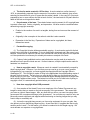


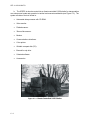


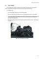
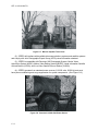


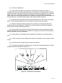


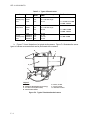
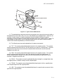
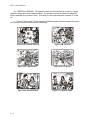


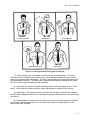


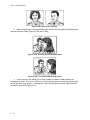
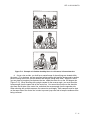
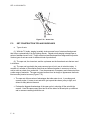

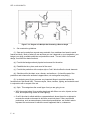
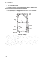
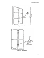


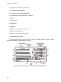
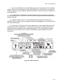


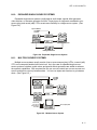


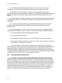


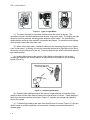
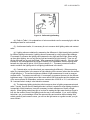
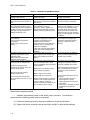


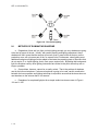


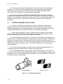

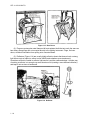

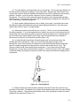


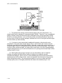
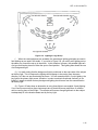


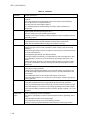


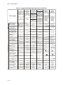

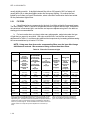
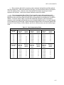
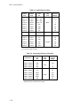


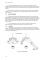
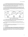


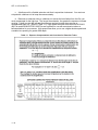

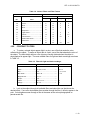
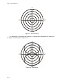
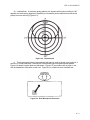
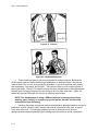

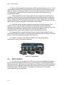
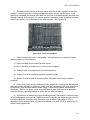
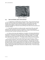
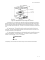
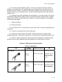
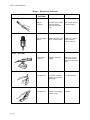
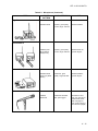
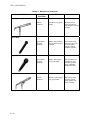

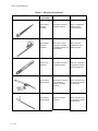


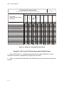


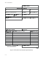
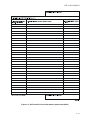


![[1 ] Oracle® Enterprise Manager](http://vs1.manualzilla.com/store/data/005669073_1-0396df232df5e560fdd03210f5126330-150x150.png)