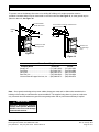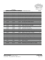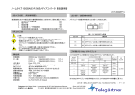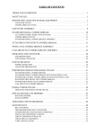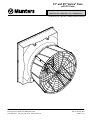
1
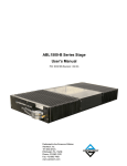
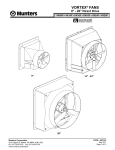
51" and 55" Vortex® Fans with FC Cone VX511FCx-FC • VX5115FCx-FC • VX512FCx-FC • VX551FCx-FC • VX5515FCx -FC • VX552FCx-FC Protected by U.S. Patent No. 6,386,828, 6616404; 6953320 Munters Corporation 4215 Legion Dr. Mason, MI 48854-1036 USA (517) 676-7070 Fax (517) 676-7078 www.munters.us FORM: QM1063 Rev. 9, January 2013 Page 1 of 17 USER'S MANUAL and INSTALLATION GUIDE TABLE OF CONTENTS Section Page Parts List......................................................................................................................3 Fan Dimentions............................................................................................................4 Installation Instruction................................................................................................ 5-11 Electrical Wiring........................................................................................................ 11-12 Operation.....................................................................................................................13 Maintenance.............................................................................................................13-14 Trouble Shooting.........................................................................................................15 Winterizing Fan...........................................................................................................15 Winter Weather Protection..........................................................................................16 Exploded View and Parts List...................................................................................17-18 Thank You Thank you for purchasing an Aerotech Vortex Fan from Munters. Munters equipment is designed to be the highest performing, highest quality equipment you can buy. With the proper installation and maintenance it will provide many years of service. PLEASE NOTE To achieve maximum performance and insure long life from your Munters product it is essential that it be installed and maintained properly. Please read all instructions carefully before beginning installation. WARRANTY For Warranty claims information see the "Warranty Claims and Return Policy" form QM1021 available from the Aerotech Ventilation System, Munters Corporation office at 1-800-227-2376 or by e-mail at [email protected]. Conditions and Limitations: • Products and Systems involved in a warranty claim under the "Warranty Claims and Return Policy" shall have been properly installed, maintained and operated under competent supervision, according to the instructions provided by Aerotech Ventilation Systems, Munters Corporation. • Malfunction or failure resulting from misuse, abuse, negligence, alteration, accident or lack of proper installation or maintenance shall not be considered a defect under the Warranty. Munters Corporation 4215 Legion Dr. Mason, MI 48854-1036 USA (517) 676-7070 Fax (517) 676-7078 www.munters.us FORM: QM1063 Rev. 9, January 2013 Page 2 of 17 UNPACKING THE EQUIPMENT Before beginning installation, check the overall condition of the equipment. Remove packing materials, and examine all components for signs of shipping damage. Any shipping damage is the customer's responsibility and should be reported immediately to your freight carrier. Fan is shipped complete with all accessories. Remove shutter, guard and cone sections before proceeding with installation. Each Fan includes: 1 – Belt Drive Fan 4 – Cone sections (all the same) 1 – Shutter 1 – Hardware Package as follows: HP1096 – 51” Standard Cone, PT/PV Shutter [A]…..12 – #14 x 1.5” Lag Screw, SS [B]…..20 – 1/4"-20 x 7⁄8" Truss Head Bolt, S.S [C]…..20 – 1/4"-20 Hex Flange, Nylock Nut, S.S. [A] [B] HP1127 – 51” Extended Depth Cone, PT/PV Shutter [C] [A]…..12 – #14 x 1.5” Lag Screw, SS [B]…..16 – 1/4"-20 x 7⁄8" Truss Head Bolt, S.S [E] [C]…..24 – 1/4"-20 Hex Flange, Nylock Nut, S.S. [E]…..8 – ¼” x 1¾” Hex Bolt. SS [F]…..8 – ¼” Flat Washer, SS [F] [G]…..8 – ¾” O.D. x ¾”L. Spacer HP1094 – 55” Standard Cone, PT/PV Shutter [A]…..12 – #14 x 1.5” Lag Screw, SS [B]…..24 – 1/4"-20 x 7⁄8" Truss Head Bolt, S.S [C]…..24 – 1/4"-20 Hex Flange, Nylock Nut, S.S. Munters Corporation 4215 Legion Dr. Mason, MI 48854-1036 USA (517) 676-7070 Fax (517) 676-7078 www.munters.us [G] FORM: QM1063 Rev. 9, January 2013 Page 3 of 17 Fan Dimensions E G E H A A C C D D K - Dia. F C J B I Fan Specifications: Hertz: 60 60 Voltage: 120/240VAC or 208-240/480VAC Phase: 1 or 3 Hertz: 50 50 Voltage: 110/208-220VAC or 190/380VAC Phase: 1 or 3 FAN DIA. A 51FCE 51" 55" 7" 7" 73/8" D B C 291/2" 73/4" 601/2" 291/2" 73/4" 601/2" 313/8" 713/16" 635/8" E F 59" 305/16" 59" 305/16" 623/4" 327/8" G H I J 5915/16" 233/16" 11" 25/16" 481/16" 233/16" 11" 25/16" 501/4" 2515/16" 113/4" 25/16" K - Dia. 631/8" 591/2" 633/4" WALL OPENING (I.D., framed) 56 / "W. x 573/4"H. 56 / "W. x 573/4"H. 60"W. x 611/4"H. 1 4 1 4 INSTALLATION INSTRUCTIONS Step 1 Construct the framed opening to correct size according to the Chart A. See Figure 1A,1B and 1C. Fan Dia. 51" 51" 55" Cone 51FC 51FCE 55FC Wall Opening (W. x H.) 1/4"W. x 573/4"H. 56 561/4"W. x 573/4"H. 60"W. x 611/4"H. Minimum Spacing 'Z' 12" recommended; 31/2" minimum 12" recommended; 51/2" minimum 12" recommended; 51/2" minimum Chart A Munters Corporation 4215 Legion Dr. Mason, MI 48854-1036 USA (517) 676-7070 Fax (517) 676-7078 www.munters.us FORM: QM1063 Rev. 9, January 2013 Page 4 of 17 'Z' H. (see Chart A) 12" Ceiling W. (see Chart A) Framing Figure 1A Frame Construction Ceiling 2 x 8 Header Boards 2x4 Framing W. (see Chart A) 2 x 8 Banner Boards H. (see Chart A) 4 x 4 Post - 5'O.C. 4 x 4 Post Figure 1B POST Construction 51" Fan with 51FC only 2 x 8 Header Boards Ceiling 2x6 Framing W. (see Chart A) H. (see Chart A) 6 x 6 Post - 5'O.C. 6 x 6 Post 2 x 8 Banner Boards Figure 1C POST Construction 51" Fan with 51FCE or 55" Fan Munters Corporation 4215 Legion Dr. Mason, MI 48854-1036 USA (517) 676-7070 Fax (517) 676-7078 www.munters.us FORM: QM1063 Rev. 9, January 2013 Page 5 of 17 Step 2A Insert fan into the framed opening from the inside. While lifting fan up tight to framing, fasten top of fan with (3) Lag Screw [A]. See Figure 2A & 2B. Next, fasten bottom of fan, then both sides with remaining (9) Lag Screw [A]. Install flashing around opening tight to fan and caulk around fan to seal. #14 x 1.5" Lag Screws [A] Figure 2A Frame Construction OUTSIDE INSIDE 2 x 4 Framing 2 x 8 Header Boards Post Step 2B If fan needs to be mounted, so that shutter does not stick into building then frame fan as shown in Figure 3. Top and sides require 4" minimum and bottom requires 2" minimum. #14 x 1.5" Lag Screws [A] WallOpening (See Chart A, Page 4) Wall Framing 4" Minimum Framing for fan, Top and Sides Figure 2B Post Construction OUTSIDE INSIDE 2 x 8 Banner Boards 2" Minimum Framing for fan, Bottom Wall Framing Figure 3 Munters Corporation 4215 Legion Dr. Mason, MI 48854-1036 USA (517) 676-7070 Fax (517) 676-7078 www.munters.us FORM: QM1063 Rev. 9, January 2013 Page 6 of 17 Step 3 Remove packaging from cone and guard sections. Step 4 Place (1) cone section on top of fan outlet with the middle of the cone section at the 12 o'clock position, as shown in Figure 4. Install (2) Truss Head Bolt [B] through hole in fan outlet and left and middle slots in cone section. Secure with Flange Nut [C]. Wafer head of each bolt must be on inside of fan outlet; flange nuts must be on outside of cone. See Figure 5. Tighten nuts finger tight until cone section fits firmly around fan outlet. Hole Location Fan Outlet Step 5 Facing fan outlet and working in a clockwise rotation, place right cone section on side of fan outlet, overlapping the first cone section. Attach it to fan outlet using (2) Truss Head Bolt [B] with Flange Nut [C], as done in Step 4. Tighten nuts finger tight at this time. Step 6 Repeat Step 5 placing bottom and left cone sections around fan outlet. The bolt in the left hole of the first cone section will need to be removed to attach the last cone section. Cone Section Hole Location Figure 4 Flange Nut [C] Cone Section (Outside) Fan Outlet (Inside) Truss Head Bolt [B] Figure 5 Step 7 Join cone sections together by installing Truss Head Bolt [B] through hole and into slot in the center of each joint. See Figure 6A and 6B. Tighten nuts finger tight at this time. For 51"FCE, join cone sections together by installing Truss Head Bolt [B] through (2) holes and into slots in the center of each joint. Flange Nut [C] DO NOT overtighten Cone Section with slot Cone Section with hole Center Slot Figure 6A Munters Corporation 4215 Legion Dr. Mason, MI 48854-1036 USA (517) 676-7070 Fax (517) 676-7078 www.munters.us Truss Head Bolt [B] Figure 6B FORM: QM1063 Rev. 9, January 2013 Page 7 of 17 Eyelets at center of Cone Section 51FC and 55FC Step 8A Insert guard into cone with the guard eyelets facing away from you. Make sure each eyelet lines up with a hole in the cone sections, and secure with (8) Truss Head Bolt [B] & Flange Head [C]. DO NOT tighten bolts at this time. See Figure 7A and 7B. Proceed to step 9. Flange Nut [C] Truss Head Bolt [B] Eyelets at center of Cone Joints Cone Guard Figure 7B 51FC & 55FC Fan Cone Fan Figure 7A 51FC & 55FC Fan cone Eyelets at center of Cone Section FOR 51FCE Eyelets at center of Cone Joints Step 8B Insert guard into cone with the guard eyelets facing away from you. Make sure each eyelet lines up with a hole in the cone sections, and secure with (8) Hex Head Bolt [E], Washer [F], Spacer [G] & Flange Nut [C]. DO NOT tighten bolts at this time. See Figure 8A and 8B. Proceed to step 9. Spacer [G] Washer [F] Hex Head Bolt [E] Flange Nut [C] Cone Guard Figure 8B 51FCE Cone Figure 8A 51FCE Cone Step 9 Push cone sections together at each joint to tighten cone around guard. Tighten wafer head bolts and nuts at all joints, taking care not to overtighten. Tighten all bolts holding guard in place. If fan was ordered with 'PT' style shutter, proceed to Step 10. If the 'PV' style shutter was ordered then proceed to Step 12. Munters Corporation 4215 Legion Dr. Mason, MI 48854-1036 USA (517) 676-7070 Fax (517) 676-7078 www.munters.us FORM: QM1063 Rev. 9, January 2013 Page 8 of 17 PT style shutter Step 10 Insert PT Shutter into fan by sliding the bottom flange of shutter into bottom shutter clips and pressing shutter inward. See Figure 9. PT Shutter Fixed Bottom Shutter Clip ! Figure 9 NOTE PT shutter extends into room 2 5/16" from back of fan. Step 11 Fasten shutter in place by rotating the side and top shutter clips over the shutter flanges. See Figure 10. Installation is now complete, proceed to Electrical Wiring Section. Figure 10 Munters Corporation 4215 Legion Dr. Mason, MI 48854-1036 USA (517) 676-7070 Fax (517) 676-7078 www.munters.us FORM: QM1063 Rev. 9, January 2013 Page 9 of 17 PV style shutter Step 12 Insert PV shutter into fan by sliding the bottom flange of shutter into bottom shutter clips and pressing shutter inward, See Figure 11A. Fasten shutter in place by rotating the side and top shutter clips over the shutter flanges, See Figure 11B. Installation is now complete, proceed to electrical wiring section. PV Shutter Figure 11A Fixed Bottom Shutter Clip Figure 11B ELECTRICAL WIRING Recommended Wire Routing: As the power cable exits the back of motor form a drip loop and then run power cable down along strut and "Zip" tie the cable to strut to prevent cable from getting tangled in the pulley or belt. See Figure 12. Then run the cable out the drain hole to the circuit breaker or control panel. (Continued on next page). Figure 12 Munters Corporation 4215 Legion Dr. Mason, MI 48854-1036 USA (517) 676-7070 Fax (517) 676-7078 www.munters.us FORM: QM1063 Rev. 9, January 2013 Page 10 of 17 ELECTRICAL WIRING ! WARNING High Voltage, disconnect power before installation. All wiring should be installed in accordance with National, State, and Local electrical codes. Fans used to ventilate livestock buildings or other rooms where continuous air movement is essential should be connected to individual electrical circuits, with a minimum of two circuits per room. For electrical connection requirements, refer to diagram on motor nameplate and to information enclosed with the Aerotech environmental control to be used. Single Phase Fans: motor overload protection should be provided for each fan. A Circuit Breaker Switch or slow blow motor type fuses must be used See Figure 13A. See Aerotech form QM1400 for proper size. Three Phase Fans: motor overload protection should be provided for each fan. A three pole motor starter or slow blow motor fuses must be used. See Figure 13B. If a frequency drive (inverter) is used, confirm that motors are rated for inverter duty at the voltage used. The installation of line reactors is recommended to reduce voltage spikes and harmonic distortion. Supplemental motor overload protection is also recommended. NOTE: A safety cut-off switch should be located adjacent to each fan. 120 or 240 VAC Power Supply for Fan L1 (H) L1 (H) T1 (H) T1 (H) L2 (N) L2 (N) T2 (N) T2 (N) G G 120 or 240 VAC Power Out to Fan Figure 13A Single Phase - Motor Overload Protection with Disconnect (SY2000 or Equivalent) Motor Starter Three Phase Power Supply for Fan L2 L3 T1 T1 L2 T2 T2 L3 T3 T3 L1 L1 Safety Cut-off Switch G Three Phase Power Out to Fan Motor G Figure 13B Three Phase - Motor Overload Protection with Disconnect NOTE: Information in parenthesis refers to 120 VAC control. Munters Corporation KEY: L1= Line 1 L2= Line 2 L3= Line 3 4215 Legion Dr. Mason, MI 48854-1036 USA (517) 676-7070 Fax (517) 676-7078 www.munters.us H =Hot N =Neutral G=Ground FORM: QM1063 Rev. 9, January 2013 Page 11 of 17 OPERATION ! 1) INITIAL START-UP: With electrical power off, verify that the fan propeller turns freely and that all fasteners are secure. Turn on electrical power and confirm that the fan operates smoothly. WARNING 2)ADJUSTMENTS: Set the fan control to the temperature shown on your Aerotech ventilations system drawing, or to a value which will provide the desired environmental conditions. Moving parts, disconnect power before servicing. Single Phase Fans: Single phase fans are designed for single speed operation only. Three Phase Fans: 1) The use of a quality frequency drive and the installation of line reactors is recommended to reduce voltage spikes and harmonic distortion. 2) Minimum operating frequency of 30 Hz. 3) Will require three pole contactors with overload protection (by others). MAINTENANCE ! WARNING ! WARNING The following inspection and cleaning procedures should be performed monthly: 1) INSPECT PROPELLER: Check that propeller is secure on motor shaft and that there are no signs of damage. The blades are of a self-cleaning design and should not require maintenance. High Voltage, disconnect power before servicing. ! WARNING Do not power wash electrical devices. ! WARNING 2) CLEAN regularly for best results: • FAN MOTOR: Remove any dust accumulation from motor using a brush or cloth. (DO NOT use a pressure washer). A clean motor will run cooler and last longer. At the same time, verify that the motor is secure in its mount. • SHUTTER: Carefully clean dust from shutter blades and frame so that shutter opens and closes freely. A brush or cloth should be used. • GUARD: Clean any dust or feathers from fan guards using a brush. Dirty guards can reduce airflow. 3) CHECK FASTENERS: For safety, all fasteners should be inspected. Tighten any loose connections. Moving parts, disconnect power before servicing. Moving parts, disconnect power before servicing. 4) INSPECT FAN CONTROL: With power disconnected, inspect all electrical connec-tions. Wiring should be secure and in good condition. Remove any dust build-up from control case and sensor using a soft brush or cloth. NEVER CLEAN ELECTRICAL EQUIPMENT WITH A PRESSURE WASHER! Munters Corporation 4215 Legion Dr. Mason, MI 48854-1036 USA (517) 676-7070 Fax (517) 676-7078 www.munters.us Continued on next page FORM: QM1063 Rev. 9, January 2013 Page 12 of 17 MAINTENANCE ! WARNING High Voltage, disconnect power before servicing. ! WARNING Moving parts, disconnect power before servicing. ! 6) CHECK DRIVE ALIGNMENT: Check to make sure the belt is centered on the idler pulley, then use a straight edge to check the Idler Propeller Motor alignment of the drive pulleys. If an adjustment Pulley Pulley Pulley is needed, remove the belt, then loosen the set Belt screw in one pulley and move it. Remember to tighten the set screw after making an adjustment. Straight Edge Drive alignment is very important for long belt life and proper operation. 7) CHECKING PULLEYS: Roll the belt off and look at both pulleys. If the pulley has grooves in it or is no longer smooth, it needs replacement. A loose or slipping belt will reduce fan performance up to 60% and cause premature belt failure. Smooth Pulley Grooved Pulley WARNING Do not power wash electrical devices. ! 5) GREASE BEARINGS: Grease bearings every 4-6 months. Use no more than 2 shots when greasing fan. • A premium non-water based grease is recommended: -Shell Alvania #2 -Mobil Mobilux #2 -Exxon Unirex N2 -Texaco Premium RB -Mobil 532 -Texaco Multifak #2 WARNING 8) BELT TENSIONING: Check condition of belt, if worn, replace belt. If belt is in good condition then make sure the tensioner is in the correct position. Looking from the back of the fan, the correct position of the tensioner is approximately the 7 o'clock position. See Figure 14A. To adjust the tensioner, loosen the M10 x 30mm bolt fastening the tensioner to the motor base and place a 27mm wrench onto the hex on the tensioner. Turn the wrench clockwise until the alignment mark is at mark 2 on the tensioner arm. See Figure 14B. Hold tensioner at this setting and tighten the M10 x 30mm bolt to 40 ft. lbs. of torque. Belt Tensioner Incorrect location Correct location Figure 14A Moving parts, disconnect power before servicing. Hex Alignment Mark Alignment Mark Munters Corporation 4215 Legion Dr. Mason, MI 48854-1036 USA (517) 676-7070 Fax (517) 676-7078 www.munters.us Figure 14B FORM: QM1063 Rev. 9, January 2013 Page 13 of 17 TROUBLE SHOOTING ! WARNING High Voltage, disconnect power before servicing. SYMPTOM Fan Not Operating ! WARNING Moving parts, disconnect power before servicing. POSSIBLE CAUSES CORRECTIVE ACTION 1. Fan control set above room temperature 2. Blown fuse or open circuit breaker 3. Propeller blade contacting fan housing 4. Fan control defective 5. Motor defective 1. Set to a lower temperature Fan OperatingInsufficient Airflow 1. Damper door jammed 2. Guard dirty 3. Frequency drive improperly adjusted 4. Incorrect Belt Tension/worn belt 1. Clean damper door & fan housing 2. Clean guard 3. See operation, Step 2 for adjustments guidelines 4. See Maintenance Section, Belt Tensioning Excessive Noise 1. Propeller blade contacting fan housing 2. Motor bearing or shaft bearing defective 3. Frequency drive improperly adjusted 1. Sand fan housing to remove high spot 1. Motor loose on mount 2. Propeller damaged 3. Motor or propeller shaft bent 1. Tighten fasteners 2. Replace propeller 3. Repair or replace motor or propeller shaft Excessive Vibration 2. Replace fuse or reset breaker 3. Realign motor in fan housing 4. Repair or replace control 5. Repair or replace motor 2. Repair or replace motor or shaft bearings 3. See operation, Step 2 for adjustments guidelines Winterizing Fan In most climates, it is probable that the ventilation system will never need to operate at a total capacity during the cold winter months. Consequently, it is advisable to "winterize" those fans which will not be used in cold weather to avoid unnecessary heat loss and condensation. To winterize, turn fan control "off". Install the insulated closure panel over the fan intake. If you don't have an insulated closure panel, a piece of rigid insulation material can be used. Remember the insulation panel must be removed before warmer weather returns. NOTE: At least one single speed fan should be left uncovered and with power available to provide air movement in the event of variable speed control difficulties. Munters Corporation 4215 Legion Dr. Mason, MI 48854-1036 USA (517) 676-7070 Fax (517) 676-7078 www.munters.us FORM: QM1063 Rev. 9, January 2013 Page 14 of 17 WINTER WEATHER PROTECTION To prevent cone or fan damage from snow or ice sliding off building roof, weather protection must be provided. A weather shelter may be constructed to cover the entire fan, See Figure 15, or snow guards may be placed on the roof, See Figure 16. Provide Weather Shelter Over Fans Snow Guards located per manufacturers recommendations* Building Wall 6" Min. Ceiling Aerotech Fan with Discharge Cone Figure 15 Aerotech Fan with Discharge Cone Figure 16 *Snow Guard Suppliers Company Name Phone No. Fax No. Snojax, Inc..................................................(717) 697-1900........ (717) 697-2452 Polar Blox...................................................(814) 629-7397........ (814) 629-9090 LM Curbs....................................................(800) 284-1412........ (903) 759-0879 Real-Tool, Inc.............................................(703) 338-4544........ (703) 338-4654 Vermont Slate & Copper Services, Inc.......(802) 888-8573........ (802) 888-8574 Note: Snow guards are designed to prevent sudden, dangerous snow and ice slides when attached to the building roof according to manufacturers recommendations. The supplier listing above is given as a reference only. Aerotech does not endorse any specific snow guard product and no performance warranty is implied. ! IMPORTANT Aerotech Ventilation Systems Product and System Warranties do not cover cone or fan damage from external sources. Munters Corporation 4215 Legion Dr. Mason, MI 48854-1036 USA (517) 676-7070 Fax (517) 676-7078 www.munters.us FORM: QM1063 Rev. 9, January 2013 Page 15 of 17 4215 Legion Dr. Mason, MI 48854-1036 USA (517) 676-7070 Fax (517) 676-7078 www.munters.us/aerotech Vortex 51"- 55" 4215 Legion Dr. Mason, MI 48854-1036 USA (517) 676-7070 Fax (517) 676-7078 www.munters.us Munters Corporation Munters Corporation FORM: QM1063 Rev. 9, January 2013 Page 16 of 17 Vortex 51"- 55" Item Catalog No. VX51 VX51 w/51FCE VX55 Quantity Part Name/Description 1 FH2651 FH3655 FH3655 Guard Kit, 51"/55" cone, PVC CTD, w/Hardware 1 2 FH3351 FH4551 FH3355 Discharge cone, Fiberglass, (1) Section 4 3 FP1155SS FP1155SS FP1155SS Propeller, BD, 3-blade w/set screws, Aluminum 1 4 FH2351 FH2351 FH2355 Fan Housing w/latches for PR shutter, FG 1 4 FH2352 FH2352 FH2356 Fan housing w/clips for PV Shutter, FG 1 5 FH2119 FH2119 FH2119 Shutter clip, right, for PV shutter, SS 3 6 FH2117 FH2117 FH2117 Shutter clip, left, for PV shutter, SS 3 7 FH2723 FH2723 FH2756 Strut, right, vortex, w/inserts, aluminum 1 8 FH2722 FH2722 FH2755 Strut, left, vortex, w/inserts, aluminum 1 9 Various* Various* Various* Motor, 56 frame 1 10 FH2810 FH2810 FH2810 Bracket, BD motor base, coated-galv. 1 11 FH2725 FH2725 FH2725 Bracket, bearing mount, coated-galv. 1 12 FH2402 FH2402 FH2402 Belt tensioner assembly with 3" idler pulley 1 FH2406 FH2406 FH2406 3" idler pulley only, with bolt FH2419 FH2419 FH2419 Tensioner arm only, aluminum 13 Various* Various* Various* Sheave, A-section, 5/8" bore, 3/16" keyseat, CI 1 14 FH2280B FH2280B FH2290B Shaft, 1" dia., steel, w/retaining pin hole 1 15 FH2057 FH2057 FH2057 Bearing, 1" bore x 1.44"CL, CI Holder 2 16 Various* Various* Various* Sheave, A-section, 1" bore, 1/4" keyseat, CI 1 17 Various* Various* Various* V-Belt, A-section, gates predator series 1 18 FH1366 FH1366 FH1366 Drive guard kit, PVC coated 1 19 KX1015 KX1015 KX1015 Latch, draw type, for PR shutter, SS 3 20 FH2131 FH2131 FH2131 Clip, shutter retainer for PR shutter, SS 3 21 PT51 PT51 PT553 Shutter, belled inlet, plastic 1 22 PV51 PV51 PV553 - KX1257 -- HP1096 HP1127 HP1094 23 - Shutter, all plastic 1 Spacer, .320"ID x .75"OD x 3⁄4"L, black 8 Hardware pkg., fan/cone install, PT/PV shutter 1 * Contact office for replacement part numbers for your fan configuration. Munters Corporation 4215 Legion Dr. Mason, MI 48854-1036 USA (517) 676-7070 Fax (517) 676-7078 www.munters.us FORM: QM1063 Rev. 9, January 2013 Page 17 of 17