1
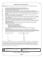
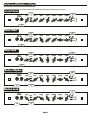
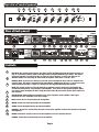
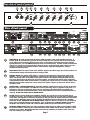
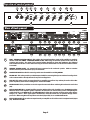
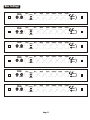
TT20 & TTH20
USER MANUAL
Laney
Classic British Amplification
Newlyn Road, Cradley Heath, West Midlands. B64 6B£
www.laney.co.uk
Dear Laney customer,
Thank you for taking the time to try out and ultimately purchase a Laney
amplifier.
Here at Laney we take great care in everything we design and build, 35
years of combined experience goes into each and every product. When
you’re producing Tube Tone heritage is everything.
I am sure with a little care and attention your Laney amplifier will give you
many years of faithful service.
Page 2
IMPORTANT SAFETY INSTRUCTIONS
WARNING: When using electric products, basic cautions should always be followed, including the following.
1.
2.
3.
4.
5.
6.
7.
8.
9.
10.
11.
12.
13.
14.
15.
16.
17.
Read all safety and operating instructions before using this product
All safety and operating instructions should be retained for future reference
Obey all cautions in the Operating instructions and on the back of the unit
All operating instructions should be followed
This product should not be used near water, i.e. a bathtub, sink, swimming pool, wet basement, etc.
This product should be located so that its position does not interfere with its proper ventilation. It should not
be placed flat against a wall or placed in a built up enclosure that will impede the flow of cooling air.
This product should not be placed near a source of heat such as stove, radiator, or another heat producing
amplifier.
Connect only to a power supply of the type marked on the unit adjacent to the power supply cord.
Never break off the ground pin on a power supply cord.
Power supply cords should always be handled carefully. Never walk or place equipment on power supply
cords. Periodically check cords for cuts or signs of stress, especially at the plug and the point where the
chord exits the unit.
The power supply cord should be unplugged when the unit is to be unused for long periods of time.
If this product is to be mounted in an equipment rack, rear support should be provided.
Metal parts can be cleaned with a damp cloth. The vinyl covering used on some units can be cleaned with
a damp cloth or ammonia based household cleaner if necessary. Disconnect the unit from the power
supply before cleaning.
Care should be taken so that objects do not fall and liquids are not spilled into the unit through any
ventilation holes or openings.
A qualified service technician should check the unit if:
The power cord has been damaged
Anything has fallen or spilled into the unit
The unit does not appear to operate correctly
The unit has been dropped or the enclosure damaged.
The user should not attempt to service the equipment. All service work is done by a qualified
service technician.
Exposure to extremely high noise levels may cause a permanent hearing loss. Individuals vary
considerably in susceptibility to noise induced hearing loss, but nearly everyone will lose some hearing if
exposed to sufficiently intense noise for a sufficient time. The U.S. Government's Occupational Safety and
Health Administration (OSHA) has specified the following permissible noise level exposure.
Duration Per Day In Hours
Sound Level dBA, slow response
8
90
6
92
4
95
3
97
2
100
1½
102
1
105
½
110
¼ or less
115
According to OSHA, any exposure in excess of the above permissible limits could result in some hearing loss. Ear
plugs or protectors in the ear canals or over the ears must be worn when operating this amplification system in
order to prevent a permanent hearing loss if exposure exceeds the limits set forth above. To ensure against
potentially dangerous exposure to high sound pressure levels it is recommended that all persons exposed to
equipment capable of producing high sound pressure levels such as this amplification system be protected by
hearing protectors while this unit is in operation.
Lightning Bolt Symbol:
This symbol is used to alert the user to the presence
of dangerous voltages and the possible risk of
electric shock.
!
Exclamation Mark Symbol:
This symbol is used to alert the user to make special note of
important operating or maintenance instructions found in the
reference manual.
SAVE THESE INSTRUCTIONS
Page 3
INTRODUCTION
Congratulations on your decision to purchase a Laney amplifier.
Laney products are designed with ease of operation as a primary objective, however to ensure you derive the best from your
new amplifier, it is important you take time to read this user manual and to familiarise yourself with the control functions and
facilities available
BEFORE
SWITCHING ON
After unpacking your amplifier check that it is factory fitted with a three pin 'grounded' (or earthed) plug. Before plugging into
the power supply ensure you are connecting to a grounded earth outlet.
If you should wish to change the factory fitted plug yourself, ensure that the wiring convention applicable to the country where
the amplifier is to be used is strictly conformed to. As an example in the United Kingdom the cable colour code for connections
are as follows.
EARTH OR GROUND - GREEN/YELLOW
NEUTRAL - BLUE
LIVE - BROWN
This manual has been written for easy access of information. The front and rear panels of each unit are graphically illustrated,
with each control and feature numbered. For a description of the function of each control feature, simply check the number with
the explanations adjacent to each panel.
Your Laney valve amplifier has undergone a thorough two stage, pre-delivery inspection, involving actual play testing, as well
as valve burn in. Valves are the most important component in your Laney valve amp. However they are also the most fragile
component. The glass envelope and valve filaments can easily be damaged in transit without any apparent signs of damage to
the box, amp or valves. Valve damage is however quite simple to diagnose and even more simple to remedy. These
procedures are explained later in this manual..
When you first recieve your Laney valve amp, follow these simple procedures:
(i) Ensure that the amplifier is set at the correct voltage for the country it is to be used in.
(ii) Connect your instrument with a high quality sheilded instrument cable. Use of cheap cables will compromise the sound of
your instrument and your amplifier.
If there is a problem with your Laney valve amplifier please contact the store where you purchased your amplifier and they will
help you resolve the problem.
Care of your Laney amplifier will prolong it's life.....and yours!. If you follow these guidelines your equipment will give you
years of playing pleasure
Page 4
Instant gratification settings
Crystal Clean
These setting should be used as a guide please experiment to get the exact tone you are after
Select BRIGHT
switch
TT20
HOT
NORMAL
DRIVE
Select PENTODE
MODE
BASS
MIDDLE
TREBLE
PRESENCE
REVERB
VOLUME
4 5 6 BRIGHT 4 5 6
4 5 6
4 5 6
4 5 6
4 5 6
4 5 6
7
7 3
7 3
7 3
7 3
7 3
7
3
3
8
8 2
8 2
8 2
8 2
8 2
8
2
2
9
9
9
9
9
9
9
1
1
1
1
1
1
1
0
10 MODERN 0
10
0
10
0
10
0
10
0
10
0
10
MODE
MUTE
Use NORMAL
input
Blues Clean
Select BRIGHT
switch
TT20
HOT
NORMAL
DRIVE
Select PENTODE
MODE
BASS
MIDDLE
TREBLE
PRESENCE
REVERB
VOLUME
4 5 6 BRIGHT 4 5 6
4 5 6
4 5 6
4 5 6
4 5 6
4 5 6
7
7 3
7 3
7 3
7 3
7 3
7
3
3
8
8 2
8 2
8 2
8 2
8 2
8
2
2
9
9
9
9
9
9
9
1
1
1
1
1
1
1
0
10 MODERN 0
10
0
10
0
10
0
10
0
10
0
10
MODE
MUTE
Use NORMAL
input
Blues Lead
Select PENTODE
MODE
Select BRIGHT
switch
TT20
HOT
NORMAL
DRIVE
BASS
MIDDLE
TREBLE
PRESENCE
REVERB
VOLUME
4 5 6 BRIGHT 4 5 6
4 5 6
4 5 6
4 5 6
4 5 6
4 5 6
7
7 3
7 3
7 3
7 3
7 3
7
3
3
8
8 2
8 2
8 2
8 2
8 2
8
2
2
9
9
9
9
9
9
9
1
1
1
1
1
1
1
0
10 MODERN 0
10
0
10
0
10
0
10
0
10
0
10
MODE
MUTE
Use NORMAL
input
Modern Rhythm
Select PENTODE
MODE
Select BRIGHT
switch
TT20
HOT
NORMAL
DRIVE
BASS
MIDDLE
TREBLE
PRESENCE
REVERB
VOLUME
4 5 6 BRIGHT 4 5 6
4 5 6
4 5 6
4 5 6
4 5 6
4 5 6
7
7 3
7 3
7 3
7 3
7 3
7
3
3
8
8 2
8 2
8 2
8 2
8 2
8
2
2
9
9
9
9
9
9
9
1
1
1
1
1
1
1
0
10 MODERN 0
10
0
10
0
10
0
10
0
10
0
10
MODE
MUTE
Select MODERN
switch
Use HOT
input
Modern Lead
Select PENTODE
MODE
TT20
HOT
Use HOT
input
NORMAL
DRIVE
BASS
MIDDLE
TREBLE
PRESENCE
REVERB
VOLUME
4 5 6 BRIGHT 4 5 6
4 5 6
4 5 6
4 5 6
4 5 6
4 5 6
7
7 3
7 3
7 3
7 3
7 3
7
3
3
8
8 2
8 2
8 2
8 2
8 2
8
2
2
9
9
9
9
9
9
9
1
1
1
1
1
1
1
0
10 MODERN 0
10
0
10
0
10
0
10
0
10
0
10
Select MODERN
switch
Page 5
MODE
MUTE
Top view of control pannel
1
2
TT20
HOT
3
DRIVE
NORMAL
5
6
7
8
9
10
BASS
MIDDLE
TREBLE
PRESENCE
REVERB
VOLUME
4
11
4 5 6 BRIGHT 4 5 6
4 5 6
4 5 6
4 5 6
4 5 6
4 5 6
7
7 3
7 3
7 3
7 3
7 3
7
3
3
8
8 2
8 2
8 2
8 2
8 2
8
2
2
9
9
9
9
9
9
9
1
1
1
1
1
1
1
0
10 MODERN 0
10
0
10
0
10
0
10
0
10
0
10
MODE
MUTE
View of back pannel
Combo
POWER CONSUMPTION
50 WATTS ~50/60HZ
MAINS SUPPLY
1
WARNING
THIS EQUIPMENT MUST
BE EARTHED.
0
~115V T1A L
~230V T500mA L
AGAINST RISK OF FIRE REPLACE ONLY
WITH SAME TYPE AND RATED FUSE
WARNING -TO REDUCE THE RISK OF
FIRE OR ELECTRIC SHOCK DO NOT
EXPOSE THIS APPLIANCE TO RAIN OR
MOISTURE.
CAUTION TO REDUCE THE RISK OF
ELECTRIC SHOCK DO NOT REMOVE
COVERS. NO USER SERVICEABLE
PARTS INSIDE. REFER SERVICING
TO QUALIFIED PERSONNEL ONLY.
14
1
0
~115V T1A
~230V T500mA
14
AGAINST RISK OF FIRE REPLACE ONLY
WITH SAME TYPE AND RATED FUSE
WARNING -TO REDUCE THE RISK OF
FIRE OR ELECTRIC SHOCK DO NOT
EXPOSE THIS APPLIANCE TO RAIN OR
MOISTURE.
CAUTION TO REDUCE THE RISK OF
ELECTRIC SHOCK DO NOT REMOVE
COVERS. NO USER SERVICEABLE
PARTS INSIDE. REFER SERVICING
TO QUALIFIED PERSONNEL ONLY.
SIDECHAIN
BYPASS
BLOWN
HT FUSE T100mA
EXTENSION SPEAKER
8 OHMS
16
17
18
INSERT
FOOTSWITCH RECORD OUT
LINE OUT
19 20 21
FX RETURN
FX SEND
23
22
24
CAUTION
RISK OF ELECTRIC SHOCK DO NOT OPEN
4 OHM
!
MADE IN THE UNITED KINGDOM BY BLT INDUSTRIES LTD.
8 OHM
SIDECHAIN
BYPASS
BLOWN
15
16
17
FOOTSWITCH RECORD OUT
18
LINE OUT
19 20 21
FX RETURN
22
FX SEND
23
2
3
NORMAL INPUT: If your aim is to obtain a crystal clear clean sound then the best results are obtained from
using this input. This input is attenuated down approximately 12dB from the Hi input. It can also be used to
obtain a distorted tone that is "tight" not "mushy" from ultra high gain humbucker type pickups.
4
DRIVE: This control sets the level of gain within the pre amplifier and goes along way to determining the
overall tonal characteristics and sensitivity of the amplifier. Lower levels of drive produce brighter, tighter
less spongy sounds, the higher the drive setting the warmer fuller the tone will be but also more compressed
and saturated.
9
10
Head
ATTENTION - DEBRANCHER LE
CORDON D’ALIMENTATION AVANT
TOUTE INTERVENTION.
ATTENTION - REMPLACER LE
INSERT
SPEAKERS
HT FUSE T100mA
HOT INPUT: Best used for distorted tones. This input provides maximum gain from the instrument to the pre
amp. It is extremely useful for guitars with single coiled or low gain humbucker type pickups. This input is
designed to introduce some LF cut into the pre signal in order to allow the pre amp to be driven to it’s
maximum without over saturating the front end of the amplifier which causes a "mushy" tones.
5
6
7
8
AVIS - RISQUE DE CHOC
ELECTRIQUE NE PAS OUVRIR.
FUSIBLE SEULEMENT PAR LE
MEME TYPE ET LE MEME CALIBRE.
24
Controls:
1
ATTENTION - DEBRANCHER LE
CORDON D’ALIMENTATION AVANT
TOUTE INTERVENTION.
ATTENTION - REMPLACER LE
FUSIBLE SEULEMENT PAR LE
MEME TYPE ET LE MEME CALIBRE.
INTERNAL
SPEAKER
CAUTION-FOR CONTINUED PROTECTION
MAINS SUPPLY
!
MADE IN THE UNITED KINGDOM BY BLT INDUSTRIES LTD.
ON OFF
15
POWER CONSUMPTION
50 WATTS ~50/60HZ
WARNING
THIS EQUIPMENT MUST
BE EARTHED.
CAUTION
RISK OF ELECTRIC SHOCK DO NOT OPEN
CAUTION-FOR CONTINUED PROTECTION
BRIGHT SWITCH: Adds brightness and sparkle to the upper frequencies of the amplifier. These upper
frequencies are more noticeable at low drive settings.
BASS: Controls the low frequency EQ in the preamplifier.
MIDDLE: Controls the mid frequency EQ in the preamplifier.
TREBLE: Controls the high frequency EQ in the preamplifier.
PRESENCE: The presence control effects the power section of the amplifier to achieve the desired level of attack
and brightness.
REVERB: Controls the overall reverb level for the amplifier. Set to your desired preference
VOLUME: Controls the overall listening level of the amplifier.
Page 6
AVIS - RISQUE DE CHOC
ELECTRIQUE NE PAS OUVRIR.
Top view of control pannel
1
2
TT20
HOT
3
DRIVE
NORMAL
5
6
7
8
9
10
BASS
MIDDLE
TREBLE
PRESENCE
REVERB
VOLUME
4
11
4 5 6 BRIGHT 4 5 6
4 5 6
4 5 6
4 5 6
4 5 6
4 5 6
7
7 3
7 3
7 3
7 3
7 3
7
3
3
8
8 2
8 2
8 2
8 2
8 2
8
2
2
9
9
9
9
9
9
9
1
1
1
1
1
1
1
0
10 MODERN 0
10
0
10
0
10
0
10
0
10
0
10
13
MODE
MUTE
12
View of back pannel
Combo
POWER CONSUMPTION
50 WATTS ~50/60HZ
MAINS SUPPLY
1
WARNING
THIS EQUIPMENT MUST
BE EARTHED.
0
~115V T1A L
~230V T500mA L
AGAINST RISK OF FIRE REPLACE ONLY
WITH SAME TYPE AND RATED FUSE
WARNING -TO REDUCE THE RISK OF
FIRE OR ELECTRIC SHOCK DO NOT
EXPOSE THIS APPLIANCE TO RAIN OR
MOISTURE.
CAUTION TO REDUCE THE RISK OF
ELECTRIC SHOCK DO NOT REMOVE
COVERS. NO USER SERVICEABLE
PARTS INSIDE. REFER SERVICING
TO QUALIFIED PERSONNEL ONLY.
14
1
0
~115V T1A
~230V T500mA
14
AGAINST RISK OF FIRE REPLACE ONLY
WITH SAME TYPE AND RATED FUSE
WARNING -TO REDUCE THE RISK OF
FIRE OR ELECTRIC SHOCK DO NOT
EXPOSE THIS APPLIANCE TO RAIN OR
MOISTURE.
CAUTION TO REDUCE THE RISK OF
ELECTRIC SHOCK DO NOT REMOVE
COVERS. NO USER SERVICEABLE
PARTS INSIDE. REFER SERVICING
TO QUALIFIED PERSONNEL ONLY.
SIDECHAIN
BYPASS
BLOWN
HT FUSE T100mA
ATTENTION - DEBRANCHER LE
CORDON D’ALIMENTATION AVANT
TOUTE INTERVENTION.
ATTENTION - REMPLACER LE
FUSIBLE SEULEMENT PAR LE
MEME TYPE ET LE MEME CALIBRE.
INTERNAL
SPEAKER
EXTENSION SPEAKER
8 OHMS
16
17
18
INSERT
FOOTSWITCH RECORD OUT
LINE OUT
19 20 21
CAUTION-FOR CONTINUED PROTECTION
MAINS SUPPLY
!
MADE IN THE UNITED KINGDOM BY BLT INDUSTRIES LTD.
ON OFF
15
POWER CONSUMPTION
50 WATTS ~50/60HZ
WARNING
THIS EQUIPMENT MUST
BE EARTHED.
CAUTION
RISK OF ELECTRIC SHOCK DO NOT OPEN
CAUTION-FOR CONTINUED PROTECTION
4 OHM
FX RETURN
FX SEND
23
24
CAUTION
RISK OF ELECTRIC SHOCK DO NOT OPEN
!
22
MADE IN THE UNITED KINGDOM BY BLT INDUSTRIES LTD.
8 OHM
SIDECHAIN
BYPASS
BLOWN
AVIS - RISQUE DE CHOC
ELECTRIQUE NE PAS OUVRIR.
Head
ATTENTION - DEBRANCHER LE
CORDON D’ALIMENTATION AVANT
TOUTE INTERVENTION.
ATTENTION - REMPLACER LE
FUSIBLE SEULEMENT PAR LE
MEME TYPE ET LE MEME CALIBRE.
INSERT
SPEAKERS
HT FUSE T100mA
15
16
17
FOOTSWITCH RECORD OUT
18
LINE OUT
19 20 21
FX RETURN
22
FX SEND
23
11
MODE SWITCH: The mode switch selects the mode in which the output section of the amplifiers functions. In
Pentode mode the two EL84 valves generate 20 watts of warm tube tone, pentode mode is the most efficient
mode, whilst in Triode mode the efficiency of the valves is reduced hence generating lower output wattage typically between 8 - 12 watts RMS depending upon the valve characteristics. If volume is what you desire then
in most cases you will set the output section to Pentode, but in a studio application where volume is less of a
concern it is possible to get enhanced harmonic content from the signal by using high drive setting in
combination with Triode mode.
12
MUTE SWITCH: Mutes the output section of the amplifier. Signal to the effects loops, line out and record out are
still maintained making silent tuning and level setting possible.
13
MODERN SWITCH: The modern switch applies a varying level of compression to the preamp section of the
amplifier. The more drive that is added to the signal the greater the level of compression applied to the
signal. This has the effect of smoothing out the signal response of the amplifier making the highs and lows
more even, this also gives the impression of increased sustain. For modern lead and rock tones a high drive
setting with the modern switch selected produces everything from a liquid solo tone to a chuncky rhythm sound.
When the modern switch is applied to a clean setting it also applies a degree of compression but the effect is
much more subtle.
14
POWER SOCKET + POWER FUSE HOLDER: For connecting amplifier to mains power-supply. The fuse protects the
AC power of the overall amplifier. Use ONLY the correct size and rating of fuse as specified on the panel. If a
fuse blows or fails and a replacement of the same size and rating is installed and this in turn blows, the
amplifier has suffered an internal malfunction. At this point immediate service from a qualified technician is
required; DO NOT TRY USING A FUSE OF HIGHER RATING.
15
HT FUSE: This fuse protects the DC power within the amplifier. Use only the correct size and rating fuse as
specified on the panel. If a fuse blows or fails and a replacement of the same size and rating is installed and it
in turn blows, the amplifier has suffered a malfunction, at this point check the output valves and replace faulty
one if required. Should the valves not be the problem, the amplifier should be checked out by a qualified
technician; DO NOT TRY USING A FUSE OF GREATER VALUE. Using fuses that are too large in current rating may
cause serious irreparable damage to the amplifier. Fuses are designed-in to PROTECT, DO NOT take chances.
The HT fuse has an LED associated with it, when the LED is ON the fuse has failed and needs replacing.
16
EXTENSION SPEAKER SOCKET: This is the socket to which you should connect an 8 Ohm extension cabinet. When
an extension cabinet is connected, the resultant impedance will be 4 Ohms and the speaker impedance-switch
should be set to 4 Ohms. Mismatched impedance will reduce the amplifiers performance and in some cases
may cause damage to your amplifier.
Page 7
24
AVIS - RISQUE DE CHOC
ELECTRIQUE NE PAS OUVRIR.
Top view of control pannel
1
2
TT20
HOT
3
DRIVE
NORMAL
5
6
7
8
9
10
BASS
MIDDLE
TREBLE
PRESENCE
REVERB
VOLUME
4
11
4 5 6 BRIGHT 4 5 6
4 5 6
4 5 6
4 5 6
4 5 6
4 5 6
7
7 3
7 3
7 3
7 3
7 3
7
3
3
8
8 2
8 2
8 2
8 2
8 2
8
2
2
9
9
9
9
9
9
9
1
1
1
1
1
1
1
0
10 MODERN 0
10
0
10
0
10
0
10
0
10
0
10
13
MODE
MUTE
12
View of back pannel
Combo
POWER CONSUMPTION
50 WATTS ~50/60HZ
MAINS SUPPLY
1
WARNING
THIS EQUIPMENT MUST
BE EARTHED.
0
~115V T1A L
~230V T500mA L
AGAINST RISK OF FIRE REPLACE ONLY
WITH SAME TYPE AND RATED FUSE
WARNING -TO REDUCE THE RISK OF
FIRE OR ELECTRIC SHOCK DO NOT
EXPOSE THIS APPLIANCE TO RAIN OR
MOISTURE.
CAUTION TO REDUCE THE RISK OF
ELECTRIC SHOCK DO NOT REMOVE
COVERS. NO USER SERVICEABLE
PARTS INSIDE. REFER SERVICING
TO QUALIFIED PERSONNEL ONLY.
14
1
0
~115V T1A
~230V T500mA
14
AGAINST RISK OF FIRE REPLACE ONLY
WITH SAME TYPE AND RATED FUSE
WARNING -TO REDUCE THE RISK OF
FIRE OR ELECTRIC SHOCK DO NOT
EXPOSE THIS APPLIANCE TO RAIN OR
MOISTURE.
CAUTION TO REDUCE THE RISK OF
ELECTRIC SHOCK DO NOT REMOVE
COVERS. NO USER SERVICEABLE
PARTS INSIDE. REFER SERVICING
TO QUALIFIED PERSONNEL ONLY.
SIDECHAIN
BYPASS
BLOWN
HT FUSE T100mA
ATTENTION - DEBRANCHER LE
CORDON D’ALIMENTATION AVANT
TOUTE INTERVENTION.
ATTENTION - REMPLACER LE
FUSIBLE SEULEMENT PAR LE
MEME TYPE ET LE MEME CALIBRE.
INTERNAL
SPEAKER
EXTENSION SPEAKER
8 OHMS
16
17
18
INSERT
FOOTSWITCH RECORD OUT
LINE OUT
19 20 21
CAUTION-FOR CONTINUED PROTECTION
MAINS SUPPLY
!
MADE IN THE UNITED KINGDOM BY BLT INDUSTRIES LTD.
ON OFF
15
POWER CONSUMPTION
50 WATTS ~50/60HZ
WARNING
THIS EQUIPMENT MUST
BE EARTHED.
CAUTION
RISK OF ELECTRIC SHOCK DO NOT OPEN
CAUTION-FOR CONTINUED PROTECTION
4 OHM
FX RETURN
FX SEND
23
24
CAUTION
RISK OF ELECTRIC SHOCK DO NOT OPEN
!
22
MADE IN THE UNITED KINGDOM BY BLT INDUSTRIES LTD.
8 OHM
SIDECHAIN
BYPASS
BLOWN
AVIS - RISQUE DE CHOC
ELECTRIQUE NE PAS OUVRIR.
Head
ATTENTION - DEBRANCHER LE
CORDON D’ALIMENTATION AVANT
TOUTE INTERVENTION.
ATTENTION - REMPLACER LE
FUSIBLE SEULEMENT PAR LE
MEME TYPE ET LE MEME CALIBRE.
INSERT
SPEAKERS
HT FUSE T100mA
15
16
17
FOOTSWITCH RECORD OUT
16
LINE OUT
19 20 21
FX RETURN
22
FX SEND
23
17
HEAD - IMPEDANCE SELECTOR SWITCH : This switches the internal impedance setting of the amplifier to match the
cabinets connected. COMBO - EXTENSION CABINET ON/OFF: When using an extension speaker set the switch to the
extension ON position. The rating of the extension cabinet should be no lower than 8 Ohmsuse the dedicated
TTC112 cabinet for the best results. When not using an extension cabinet make sure the extension cabinet selector
is set to OFF
18
INTERNAL SPEAKER SOCKET: 1/4" output-jack factory-connected to the 'on-board' speaker. With no extension
cabinet connected, ensure that switch (17) is set to Internal.
19
FOOTSWITCH SOCKET: Provided for connecting an FS1 mono footswitch for switching REVERB
20
RECORD OUT: This socket provides a pre EQ’d output suitable for connecting directly to an outboard recording device
such as a Porta studio or directly into a PC or any such recording device.
21
LINE OUT: This socket provides an output from the pre-amplifier, post effects-loop and may be used to drive other
power-amplifiers, effects-units or mixing-desks: nominal level 0dBu.
22
RETURN SOCKET: This is provided to receive the output of an external effects-unit being driven from the send socket
(24).
23
EFFECTS MODE SWITCH: For normal amplifier operation without effects this should be set to the BYPASS position.
When the whole of the amplifier signal is required to be directed to an external effect, such as a Graphic-EQ, the
switch should be set to INSERT mode. The SIDE CHAIN mode allows the connection of effects-units such as delays,
flangers, etc., where a direct signal-path is maintained to avoid the normal loss of dynamics through effectsprocessors. When using this mode any effects-unit should, if possible, be set to 'EFFECT ONLY' mode.
24
EFFECTS SEND SOCKET: This provides an output from the pre-amplifier to drive effects-units in conjunction with (23) &
(22). Nominal level 0dBu.
Page 8
24
AVIS - RISQUE DE CHOC
ELECTRIQUE NE PAS OUVRIR.
Notes
The following hints and tips are provided so that you can get the best performance out of your Laney valve amplifier.
These are only guidelines and should be adapted for your own preferences:1: Valve amplifiers take a short time to 'warm up' to optimum operating temperature. To get optimum performance out of
your TT amplifier allow the amplifier to 'warm up' for three mins. before you begin playing.
2: The position of an amplifier in a room has an effect upon the overall sound characteristics. If you wish to increase the
bass response of your amplifier place the amplifier on the floor. If you wish to reduce the bass response of your amplifier
place the amplifier on a stand.
3: Do not place you amplifier hard up against a wall as this will reduce the air circulating around the back of the unit and
may result in overheating.
4: Connecting your guitar to either the 'Hot' or “Normal” input has an effect on the sound, regardless of the guitar
type/pickup configuration. The 'Hot' socket provides more gain and extended treble, but with less BASS. The 'Normal'
socket provides a full range signal with extended low frequencies and lower gains. You should experiment with both inputs
to find the one which suits your guitar, style of playing and gives you the most tonally pleasing results.
5: When using the 'BRIGHT SWITCH' on the amplifier keep in mind that it has a greater audible effect the lower the amount
of distortion produced by the preamplifier. At some distortion levels the 'BRIGHT SWITCH' may appear to have no effect at
all.
VALVE REPLACEMENT AND TROUBLE SHOOTING
The valves in your new valve amplifier will eventually need replacing due to wear, this is normal with valve amps. In most
instances you should be able to effect valve replacement yourself without incurring the costs of a service engineer.
Following are some of the most likely symptoms of valve malfunction and a suggested method of correction.
Normally valve amps give optimum performance when fitted with matched sets of output valves as factory fitted to all
Laney valve amps. NB: Damage will not occur by not fitting matched sets although the amplifiers performance may be
impaired.
Symptom 1
Amp connections have been performed correctly but power light fails to illuminate
Solution 1
Check time delay POWER FUSE and replace if necessary:230V - T500mAL 250V
115V - 1AL 250V
100V - T1AL 250V
Symptom 2
Power light illuminates, no sound out put
Solution 2
Check secondary HT fuse and if the LED is lit then the fuse has blow. Replace with: T100mAL 250V
Symptom 3
Secondary HT fuse (T100mAL) blows repeatedly. This is a strong indication of a damaged output valve. The following
chart shows the valve layout and the function each performs.
Page 9
Notes
Rear View
V5 V4 V3
V1 ECC83 Low Noise Type
V2 ECC83 Soft distortion Type
V3 ECC83 General Purpose type
V4/V5 EL84 Matched Pair
V2 V1
part # 005548A
part # 005570
part # 005548C
part # 005562
Solution 3
Replace the secondary fuse and turn on the power. View the output valves. If one valve fails to light up, replace that
valve. If the output valves check out ok, another cause of a blown secondary fuse is a damaged preamplifier valve. Start
with valve V1 and replace it, follow the above procedure. If the symptom persists, consult a qualified engineer, do not fit
higher rated fuses.
Symptom 4
No pre amplifier boost.
Solution 4
Replace pre amplifier tubes V1 or V2 or a combination.
Symptom 5
Slow loss of power
Solution 5
Check first for damaged output valves (glowing ,flashing or dead) by using the procedures described in symptom 3.
All of these trouble shooting procedures can be performed quickly, without the aid of any sophisticated test gear. We
suggest that you always maintain spare valves for emergency purposes. Keep your Laney free of dirt, dust and moisture to
prevent performance failure Never subject your valve amp to environmental conditions that would not be comfortable to
you!
Page 10
User Settings
TT20
HOT
NORMAL
TT20
HOT
NORMAL
TT20
HOT
NORMAL
TT20
HOT
NORMAL
TT20
HOT
NORMAL
TT20
HOT
NORMAL
DRIVE
BASS
MIDDLE
TREBLE
PRESENCE
REVERB
VOLUME
4 5 6 BRIGHT 4 5 6
4 5 6
4 5 6
4 5 6
4 5 6
4 5 6
7
7 3
7 3
7 3
7 3
7 3
7
3
3
8
8 2
8 2
8 2
8 2
8 2
8
2
2
9
9
9
9
9
9
9
1
1
1
1
1
1
1
0
10 MODERN 0
10
0
10
0
10
0
10
0
10
0
10
DRIVE
BASS
MIDDLE
TREBLE
PRESENCE
REVERB
BASS
MIDDLE
TREBLE
PRESENCE
REVERB
BASS
MIDDLE
TREBLE
PRESENCE
REVERB
BASS
MIDDLE
TREBLE
PRESENCE
REVERB
BASS
MIDDLE
TREBLE
PRESENCE
REVERB
MUTE
MODE
MUTE
MODE
MUTE
VOLUME
4 5 6 BRIGHT 4 5 6
4 5 6
4 5 6
4 5 6
4 5 6
4 5 6
7
7 3
7 3
7 3
7 3
7 3
7
3
3
8
8 2
8 2
8 2
8 2
8 2
8
2
2
9
9
9
9
9
9
9
1
1
1
1
1
1
1
0
10 MODERN 0
10
0
10
0
10
0
10
0
10
0
10
Page 11
MODE
VOLUME
4 5 6 BRIGHT 4 5 6
4 5 6
4 5 6
4 5 6
4 5 6
4 5 6
7
7 3
7 3
7 3
7 3
7 3
7
3
3
8
8 2
8 2
8 2
8 2
8 2
8
2
2
9
9
9
9
9
9
9
1
1
1
1
1
1
1
0
10 MODERN 0
10
0
10
0
10
0
10
0
10
0
10
DRIVE
MUTE
VOLUME
4 5 6 BRIGHT 4 5 6
4 5 6
4 5 6
4 5 6
4 5 6
4 5 6
7
7 3
7 3
7 3
7 3
7 3
7
3
3
8
8 2
8 2
8 2
8 2
8 2
8
2
2
9
9
9
9
9
9
9
1
1
1
1
1
1
1
0
10 MODERN 0
10
0
10
0
10
0
10
0
10
0
10
DRIVE
MODE
MODE
MUTE
BLT Industries LTD.,
Newlyn Road
Cradley Heath
West Midlands
B64 6BE
Tel: (00 44) (0)1384 633821
Fax: (00 44) (0)1384 639186
Web Site http:/www.laney.co.uk
In the interest of continuing product development BLT Industries reserves the right to change specification without prior notice.