1
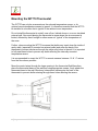
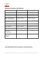
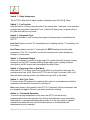
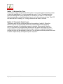
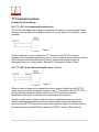
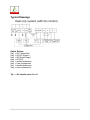
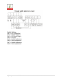
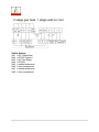
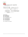
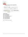
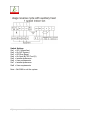
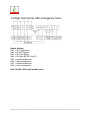
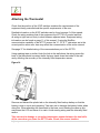
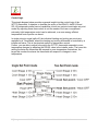
ECOMM Series WT770 Installer Manual
This document is not typically left with the user as it contains information on setting
values which, if not correctly set may damage the heating, cooling or air conditioning
system or seriously affect its performance or energy consumption.
Great effort has been taken to making the WT770 thermostat system intuitive,
reliable and easy to install. Using a common sense approach to the installation will
ensure this product is installed easily and to the customer’s satisfaction. Please read
and understand this instruction manual so that installation, testing and commissioning
process is undertaken in an efficient and effective manner.
This manual is to be used in conjunction with the supplied User Manual.
Great care has been taken in the preparation of this manual. KCRS takes no responsibility for errors or
omissions contained in this document. It is the responsibility of the user to ensure this thermostat, or the
equipment connected to it is operating to their respective specifications and in a safe manner.
Due to ongoing product improvement KCRS reserves the right to change the specifications of the WT770
thermostat (or its components) without notice.
1|Page
WT770 Advanced Installer Manual V.3
Table of Contents
Installation
Mounting the wall Controller
Setting the Hardware Dip Switches
TT Terminal Functions
Outside Air Sensor Wiring
Remote Air Temperature Sensor Wiring
Averaging Temperature Sensors
Remote ON / OFF Function
Using the “Occupancy Mode
Supply Air Temperature Monitoring
Typical Drawings
Attaching the Thermostat
Advanced Installer Settings
Commissioning
Using Remote Temperature Sensors
Advanced Functions
Specifications
Sensor Reference Table
Troubleshooting
2|Page
Page 3
Page 4
Page 5
Page 8
Page 8
Page 8
Page 9
Page 9
Page 9
Page 10
Page 11
Page 21
Page 22
Page 31
Page 33
Page 35
Page 37
Page 37
Page 38
WT770 Advanced Installer Manual V.3
Installation
As with any air conditioning project undertaken, careful installation is the key to a
successful outcome.
The steps required to install the WT770 thermostat are:
1. Read and understand this manual and the User Manual.
2. Mount the WT770 Sub-Base in a suitable location.
3. Set the 8 DIP switches to match the need of the project / user.
4. Wire the optional remote temperature sensor(s) or switches if required.
5. Power up the air conditioning system.
6. Set the installer software options (if required).
7. Program and set up the WT770 thermostat. ( Consult User Manual ).
8. Test the heating, cooling and other functions – Commissioning.
For convenience the layout of this manual is in the same order as the steps listed
above.
3|Page
WT770 Advanced Installer Manual V.3
Mounting the WT770 Thermostat
The WT770 can only be as accurate as the onboard temperature sensor, or its
optional remote temperature sensor(s) permit. It is therefore essential that the WT770
be installed in a location that is typical of the ambient room temperature.
Do not install the thermostat in a draft, near a floor, behind doors or on a non‐insulated
external wall. Also avoid placing the thermostat in areas where the air movement is
limited, affected by direct sunlight or other areas not “typical” of the temperature of
the room.
Further, when mounting the WT770 be aware that drafts may travel down the inside of
cavity walls, (especially if mounted on external walls) and enter the back of the
thermostat or sensor enclosure through the cable entry holes in the wall. It is important
to fully seal these holes to prevent any drafts affecting the internally mounted
temperature sensor.
It is recommended to mount the WT770 or remote sensors between 1.5 & 1.7 metres
from the floor where possible.
Move the control wires through the large opening in the thermostat Sub-Base then
place the thermostat base on the wall and using appropriate screws, firmly attach the
thermostat base to the wall. Block any holes where cables enter the back of the
thermostat to prevent drafts entering through these holes affecting the sensor.
4|Page
WT770 Advanced Installer Manual V.3
Setting the Hardware Dip Switches
Switch
Off
On
Sw1 – Fan Speeds
1 Speed Fan
3 Speed Fan
Sw2 – Equipment Type
Heat / Cool
Heat Pump (O/B terminals)
Sw3 – Stages
1 Stage
2 Stages
Sw4 – Reversing Valve
If Sw2 = ON – Heat Pump
Energize in Cool (O)
Energize in Heat (B)
Sw4 – Fan Mode
If Sw2 = OFF – Heat/Cool
Fan Control by Heater(HG)
Fan Control by WT770 (HE)
Sw5 – Anti cycle timer
Off
4 Minutes
Sw6 – Operation
Manual Thermostat
Programmable Thermostat
Sw7 – Minimum Run
2 Minutes
6 Minutes
Sw8 – Program Type
If Sw6 = ON
– Programmable
Commercial Program
Residential Program
Sw8 – Set points
If Sw6 = OFF
– Manual
Single Set point
Two Set points
Typical drawings have been provided on page 11 of this manual that will
assist with the selection of the correct positions for these function switches.
5|Page
WT770 Advanced Installer Manual V.3
Switch 1 – Relay Assignment
The WT770 is fitted with 5 relays capable of switching up to 24VAC @ 1Amp.
Switch 1 – Fan Function.
Sets the function of these relays as either 3 fan speeds with 1 heat and 1 cool operation
or single fan speed with 2 heat and 2 cool, in either HP (heat pump / reverse cycle) or
HC (heat with add on cool) mode.
Switch 2 – Equipment Type.
Both heat with add on cool or heat pump types of systems can be controlled by the
WT770.
Heat Cool System uses the “W” terminal(s) only for heating and the “Y” terminal(s) only
for cooling.
Heat Pump systems use the “Y” terminal(s) for BOTH heating and cooling (the
compressor). The “W1” terminal to control the reversing valve which determines
heating or cooling mode.
Switch 3 – Equipment Stages.
When it is necessary to control a single stage A/C system fitted with auxiliary heating
elements, turn Sw3 OFF thereby selecting single stage mode. Heating elements
controlled by the W2 output are now assigned as stage 2 heat.
Switch 4 – Reversing Valve or Fan Mode.
When the WT770 is set for Heat Pump mode (Sw2 is on) then this switch sets the
reversing valve logic (O/B). When the WT770 is set for Heat Cool mode (Sw2 is off)
then this switch sets the mode for the Heater fan logic (HG or HE mode).
Switch 5 – Anti Cycle Timer.
To protect some A/C systems it is preferred that under no circumstances should the
compressor start within 4 minutes of it switching off.
Note: when power is first applied to the WT770 it “assumes” that the compressor has
just stopped and applies this anti cycle delay time before starting.
Switch 6 – Thermostat Operation.
To suit the varying requirements of the user, the WT770 can be set as a
programmable thermostat using the time clock to automatically control the building
temperature to a programmed temperature profile or to the very simple to operate
manual mode where the user turns the thermostat on or off and adjusts the
temperature set point manually.
6|Page
WT770 Advanced Installer Manual V.3
Switch 7 – Minimum Run Time.
To conserve energy and protect the A/C system it is recommended to limit the number
of times the heating and / or cooling system can run in 1 hour. This switch sets the
minimum heating and cooling equipment to a minimum run time of 2 or 6 minutes.
Once the heating or cooling has started it must run for this minimum set time. The LCD
will flash the word “Heating” or “Cooling” whenever this timer is in effect.
Switch 8 – Thermostat Control Logic.
This switch also has two functions based on the position of switch 6. When the
WT770 is set as a programmable thermostat, switch 8 determines whether a
commercial program or residential program is selected. When switch 6 has the
WT770 used as a non programmable thermostat, this switch sets single set point
mode imitating a simple mechanical thermostat or whether a separate heating and
cooling set point can be selected by the user. Two set point mode also permits the user
to select a separate day and night set point if required.
7|Page
WT770 Advanced Installer Manual V.3
TT Terminal Functions
Outside Air Sensor Wiring
Set “TT = OA” in the advanced installer menu.
The WT770 can display the outside air temperature if desired. Some advanced control
functions such as high and low balance points rely on this sensor to be fitted for correct
operation.
Figure 1
Using a single pair of wires connect the “TT” terminals in the WT770 to the two
terminals in the outside air temperature sensor. If the outside air sensor fails two dashes
will be shown on the LCD where the outside air temperature would normally be
displayed to alert you of the problem. Remote Air Temperature Sensor Wiring.
Set “TT = RS” in the advanced installer menu. (Default)
Figure 2
When you wish to measure the temperature from a location distant from the WT770,
simply connect a remote temperature sensor to the “TT” terminals in the WT770. This
will automatically disable the sensor fitted to the WT770 and use the remote
temperature sensor(s) to control the room temperature (See Figure 1).
Should you wish, you can easily switch the remote temperature sensor on and off
thereby switching temperature sensing locations between the remote temperature
sensor and the WT770 temperature sensor when required. Simply fit an inline switch in
the sensor wiring or order KCRS part number A770RS-01 sensor. (See Figure 2.)
8|Page
WT770 Advanced Installer Manual V.3
Averaging Temperature Sensors
Set “TT = AV” in the Advanced Installer Menu.
The WT770 can average the sensed temperature equally between the remote
temperature sensor(s) and the one fitted to the WT770 if required. See figure 1
on the previous page for details on wiring the sensor. The WT770 will auto‐detect this
sensor and automatically average the two sensors values to control the room
temperature.
Remote ON / OFF Function
Set “TT = OF” in the advanced installer menu.
The WT770 can be connected to an external dry contact. When
this contact is closed the WT770 will turn OFF. See figure 3. When the WT770 has
been switched OFF via the “TT” terminals the word “OFF” will flash in the LCD to
indicate that this has been the shutdown method. The WT770 will return to the user
settings when this switch is open.
Figure 3
Using the “Occupancy Mode”
Set “TT = OC” in the advanced installer menu.
The WT770 can alternate between the user preferred set points and an installer
pre programmed set point when required. Simply wire a remote switch to the WT770
“TT” terminals (see figure 3). When the switch is open the user settings will control the
room temperature. When the switch is closed the Installer “Oc” (Occupied Cooling
value) & “Oh” (Occupied Heating value) settings will be used to control the
room temperature.
9|Page
WT770 Advanced Installer Manual V.3
Supply Air Temperature Monitoring
Set “TT = DA” in the advanced installer menu.
In this mode, the WT770 will broadcast this sensor temperature value to ModBus
ONLY, this value is not used by the WT770 nor is it displayed on the LCD. It is
expected that this information is used for supervisory functions or equipment control
feedback. Also, as this is an analogue input, by monitoring a switched resistor network
your supervisory software can decode a number of digital states.
10 | P a g e
WT770 Advanced Installer Manual V.3
Typical Drawings
Switch Settings
Sw1 = Off (1 speed fan)
Sw2 = Off (HC System)
Sw3 = Off (Single Stage)
Sw4 = Off (HG)
Sw5 = Installer preference
Sw6 = User requirements
Sw7 = Installer preference
Sw8 = User requirements
Tip ---- Set Installer menu Fn = H
11 | P a g e
WT770 Advanced Installer Manual V.3
Switch Settings
Sw1 = Off (1 speed fan)
Sw2 = Off (HC System)
Sw3 = Off (Single Stage)
Sw4 = N/A
Sw5 = Installer preference
Sw6 = User requirements
Sw7 = Installer preference
Sw8 = User requirements
Tip --- Set Installer menu Fn = C
12 | P a g e
WT770 Advanced Installer Manual V.3
Switch Settings
Sw1 = Off (1 speed fan)
Sw2 = Off (HC System)
Sw3 = Off (Single Stage)
Sw4 = Off (HG)
Sw5 = Installer preference
Sw6 = User requirements
Sw7 = Installer preference
Sw8 = User requirements
13 | P a g e
WT770 Advanced Installer Manual V.3
Switch Settings
Sw1 = Off (1 speed fan)
Sw2 = Off (HC System)
Sw3 = On (Two Stage)
Sw4 = Off (HG)
Sw5 = Installer preference
Sw6 = User requirements
Sw7 = Installer preference
Sw8 = User requirements
14 | P a g e
WT770 Advanced Installer Manual V.3
Switch Settings
Sw1 = Off (1 speed fan)
Sw2 = On (HP System)
Sw3 = Off (One Stage)
Sw4 = On Heat (B)/ Off Cool (O)
Sw5 = Installer preference
Sw6 = User requirements
Sw7 = Installer preference
Sw8 = User requirements
Note – Set SW4 to suit the system
15 | P a g e
WT770 Advanced Installer Manual V.3
Switch Settings
Sw1 = Off (1 speed fan)
Sw2 = On (HP System)
Sw3 = Off (One Stage)
Sw4 = On Heat (B) / Off Cool (O)
Sw5 = Installer preference
Sw6 = User requirements
Sw7 = Installer preference
Sw8 = User requirements
Note – Set SW4 to suit the system
16 | P a g e
WT770 Advanced Installer Manual V.3
Switch Settings
Sw1 = Off (1 speed fan)
Sw2 = On (HP System)
Sw3 = Off (One Stage)
Sw4 = On Heat (B)/ Off Cool (O)
Sw5 = Installer preference
Sw6 = User requirements
Sw7 = Installer preference
Sw8 = User requirements
Note – Set SW4 to suit the system
17 | P a g e
WT770 Advanced Installer Manual V.3
Switch Settings
Sw1 = Off (1 speed fan)
Sw2 = On (HP System)
Sw3 = On (Two Stage)
Sw4 = On Heat (B)/ Off Cool (O)
Sw5 = Installer preference
Sw6 = User requirements
Sw7 = Installer preference
Sw8 = User requirements
Note: Set W3 = EH in the installer menu.
18 | P a g e
WT770 Advanced Installer Manual V.3
Switch Settings
Sw1 = Off (1 speed fan)
Sw2 = Off (HC System)
Sw3 = Off (Single Stage)
Sw4 = Off (HG)
Sw5 = Installer preference
Sw6 = User requirements
Sw7 = Installer preference
Sw8 = User requirements
Tip---Set Installer menu Fn = H
19 | P a g e
WT770 Advanced Installer Manual V.3
Switch Settings
Sw1 = Off (1 speed fan)
Sw2 = Off (HC System)
Sw3 = On (Two Stage)
Sw4 = Off (HG)
Sw5 = Installer preference
Sw6 = User requirements
Sw7 = Installer preference
Sw8 = User requirements
20 | P a g e
WT770 Advanced Installer Manual V.3
Attaching the Thermostat
Check that the position of the 8 DIP switches matches the requirements of the
equipment being controlled and the specific requirements of the user.
Detailed information on the 8 DIP switches can be found on page 5 of this manual.
Check the wiring matches that of the equipment the WT770 is to control and that
all wiring is tight and not likely to short between adjacent wires. Equipment wiring
information can be found on page 11 of this manual. If using the ModBus
communication capability of the WT770 ensure the “A”, “B” & “T” data wires are in the
correct position as an error here may affect the communication of the entire network.
See page 37 for detailed wiring of the communications port of the WT770.
Using masking tape or similar, block the hole in the wall where the wiring enters the
back of the thermostat to prevent drafts that may travel down the inside of the wall
cavity affecting the accuracy of the internally fitted temperature sensor.
Figure 14
Remove and discard the plastic tab on the internally fitted backup battery so that the
battery is now in circuit and operating. Take care not to damage the battery holder when
doing this. When attaching the thermostat to the base, avoid twisting the case as this
may stress the LCD and cause it to crack. Avoid running wiring near the internally fitted
sensor.
Take care not to damage or crush the temperature sensor between the two half’s
of the case when you close the WT770 case. Check this sensor location.
21 | P a g e
WT770 Advanced Installer Manual V.3
Advanced Installer Settings
The WT770 is fitted with many advanced functions that can be fine tuned by the
installer to specifically match the needs of the project of the user. Normally these
functions will not need to be altered from the factory default position however, there may
be times when you wish to alter a setting or control capability so that the WT770
performance will perfectly match a particular application. On the next few pages there is
detailed explanation of these functions and their range of control.
While in the advanced installer menu, all WT770 equipment control functions will be
suspended. Normal equipment operation will continue when you have exited this
menu (after any anti cycle delays or safety delays have terminated).
Using the Installer Menu
To move forward through the Installer menu items tap the “O/RIDE” button.
To move backwards through the Installer menu items tap the “PROG” button.
To adjust a value in the Installer menu tap the (�) or down (�) buttons.
To exit the installer menu tap the “Mode” button, the “Fan” button or wait 60 seconds.
Entering the Installer Menu
To enter the Installer menu, press and hold the O/RIDE button for 15 seconds.
After 15 seconds the LCD will show “88:15” (eight eight one five).
Adjust this value to “88:21” – (eight eight two one) the factory default PIN (or your
previously selected value) by using the up (�) or down (�) button. Tap the O/RIDE
button to enter the menu.
If you have entered the correct PIN you will be given the first menu option, if you have
entered an incorrect PIN you will be exited from this menu.
Default Installer Values are shown in the examples in the following pages.
22 | P a g e
WT770 Advanced Installer Manual V.3
PN = 21 Keyboard Lock PIN
This is the required PIN for future entry into the Installer menu.
Range 00 to 99 in 01 steps. To prevent accidental PIN changes, you must press and
hold the
� or � buttons for longer than 1 second to change the PIN value.
(Caution, if you change this value and forget your new PIN, you may need to
return the WT770 to place of purchase for unlocking, there will be a fee for this
service)
LC = 0 Keyboard Lock level
Programmable Mode (SW6=ON)
LC = 00 ‐ Key board Lock OFF.
LC = 01 ‐ All buttons are locked except the Temperature +/‐ buttons*.
LC = 02 ‐ All buttons are locked except the O/Ride button & Temp +/‐ buttons*.
LC = 03 ‐ Fan and Program buttons are locked*.
LC = 04 ‐ Fan, Program and Override buttons are locked *.
LC = 05 ‐ All buttons locked except O/Ride.
LC = 06 ‐ All Buttons locked.
Manual Mode (SW6=Off)
LC = 00 ‐ Key board Lock OFF.
LC = 01 ‐ All buttons are locked except the Mode button.
LC = 02 ‐ All buttons are locked except the Mode and temperature +/‐ button*.
LC = 03 ‐ Fan & O/ride buttons are locked*.
Mode button can only select Auto (Heat & Cool) and off.
LC = 04 ‐ O/Ride Button is locked*.
Mode button can only select Auto (Heat & Cool) and off.
(*Note the temp +/‐ buttons range can be limited in the HL & CL menu )
23 | P a g e
WT770 Advanced Installer Manual V.3
HL = 35 (95F) Heating Limit (or High Limit)
The highest Heating value permitted to be set by the user.
Adjustable between 0~35c (32~95F).
CL = 5 (41F) Cooling Limit (or Low Limit)
The lowest Cooling value permitted to be set by the user.
Adjustable between 5 ~37c. (41~98F).
CF = C Temperature display Format
Deg C or deg F display type. (effects all user and installer menu items)
C1 = 0.0 Fitted Sensor Calibration
Calibration Offset for the internal sensor.
Adjustable range +/‐ 4.5 deg C (+/‐9 F). in 1.0 Deg steps
tC = 12 Time Clock
tC = 12 ‐ 12 Hour Time Clock.
tC = 24 ‐ 24 Hour Time Clock.
tC = 0 ‐ No time clock shown (Manual mode only–SW6=off)
tD = 0 Temperature Display
TD = 00 ‐ WT770 will display both the Room & Set Temperature.
TD = 01 ‐ WT770 will display set temperature only.
AH = 2 After Hours Override Timer
Start / Stop Mode ‐ Commercial Thermostat Mode (Sw6=on, Sw8=off)
After hour run time period ‐ Adjustable range 0 (off) to 12 hours in 0.5 hour steps.
Setback (1, 2, 3, 4) mode – Residential programmable Mode (Sw6=on, Sw8=on)
Temporarily program override period.
Off= Override till next program change or 1‐12 hours (fixed time override)
24 | P a g e
WT770 Advanced Installer Manual V.3
SC = OFF Stop Cooling temperature (Comercial Mode)
Start/stop mode Only. (Sw6=on, Sw8=off).
Cooling temperature that will be maintained when running the “STOP” program.
(Night Setback) Adjustable between 5 ~37c. (41~98F) + OFF.
SH = OFF Stop Heating temperature (Comercial Mode)
Start/stop mode Only. (Sw6=on, Sw8=off).
Heating temperature that will be maintained when running the “STOP” program.
(Night Setback) Adjustable between 5 ~35c. (41~95F) + OFF.
Db = 1 Single Set Point Dead band (See page 31 for more information)
Dead band between heat and cool set point when in single set point mode
(sw8 off). Adjustable between 0 and 5 deg in 0.5 c steps.
FO = 0/2 Fan Options ‐ Advanced Fan Functions
This function is only enabled when the selected fan mode is Fan On.
“FAN ON” will be displayed in the LCD to confirm this mode.
FO = 0 ‐ (Default Residential mode).The fan will run continuously ‐, 24 hours a day
7 days a week.
FO = 1 ‐ The fan will continue to run after the cooling stops to ensure the
maximum fresh air ventilation and to aid in cooling. The fan will stop after the
heating stops. (This is done to prevent cold drafts that may occur on cold days
when A/C system is heating).
FO = 2 ‐ (Default in Start Stop Mode).Available only if in Programmable Mode
(Sw6=on). The Fan will Run continuously from program # 1 (or Start) Program to
program #4 (or Stop) program and then run in AUTO mode overnight to maintain
the night time set points.
FO = 3 ‐ Available only if in Programmable Mode (Sw6 = on). This mode is the
combination of option 1 and option 2 given above.
FP = 1 Fan Purge Time Period (Fan run on)
If fan mode is Auto Fan, the indoor fan will run for FP=XX minutes after heating or
cooling has stopped to extract any stored energy in the coils etc –
(Necessary for electric element heating). Adjustable between off to 5 minutes in 1
minute intervals.
25 | P a g e
WT770 Advanced Installer Manual V.3
Fn = A Function ‐ Available Equipment Modes
FN = A ‐ Select if controlling a Heating & Cooling system.
FN = C ‐ Select if controlling a Cooling only system. (disables heating menus)
FN = H ‐ Select if controlling a Heating only system. (disables cooling menus)
H3 = Of W2 relay Function
Only operates in single fan speed HP mode. (Sw1=off & Sw2=on).
H3 = Of ‐ W2 relay is used as 2nd (or 3rd) stage Auxiliary heat.
H3 = EH ‐ W2 relay is used to control an Emergency Heating system.
H3 = AH ‐ W2 relay is used to control a Add On Heat system.
H3 = FF ‐ WT770 set up in “Fossil Fuel” Mode (Comp stops with Aux heat)
H3 = AL ‐ SMT will permit both Aux heat & E. Heating mode (both use W2 relay)
tt = RS TT terminal Function (see page 9 for more detail on this function)
tt = OA ‐ Connect the outside air temperature sensor to the TT terminals to
display the outside Air Temperature.
(Required for all outside air control functions to operate.)
tt = RS ‐ Connect the remote room temperature sensor to the TT terminals to
measure the temperature at a remote location away from the WT770.
(Note: This completely disables the temperature sensor fitted to the WT770)
tt = AV ‐ The TT terminals will average the temperature measured by the WT770
internal sensor and remote room temperature sensor.
tt = OF ‐ A closed contact on the TT terminals will switch the WT770 On or
OFF. (More detail on this function provided on page 11 of this manual.)
tt = OC ‐ A closed contact on the TT terminals will switch the WT770 to
Occupied Mode, where the oC & oH temperatures will replace the user set
temperatures. (See page 11 of this manual for more detail on this function.)
tt = DA ‐ The WT770 will broadcast the measured temperature from the
remote temperature sensor via ModBus. It will not display this value on the LCD,
nor is it used for any control option. This mode is intended to provide system feedback
to the ModBus master only.
26 | P a g e
WT770 Advanced Installer Manual V.3
AF = 0 Anti‐Freeze Function
AF = 0 ‐ Antifreeze function off.
AF = 1 ‐ Room temperature will not be permitted to fall below 5c (41F).
oH = Off Occupied Mode Heat Set (see page 11 for more information).
Only operates if TT=OC. This is the heating temperature that will be used in “Occupied
mode” and will temporarily replace the user heat set point while the TT terminals are
shorted together. Adjustable range 0‐35c (32 – 95f)
oC = OFf Occupied Mode Cool Set (see page 11 for more information).
Only operates if TT=OC. This is the cooling temperature that will be used in “Occupied
mode” and will temporarily replace the user cool set point while the TT terminals are
shorted together. Adjustable range 5‐37c (41 – 98f)
SP = 2 Stage 1 Span (See page 31 for an overview of this control function)
Hysteresis for Stage 1. (difference between heating and cooling turning on and off)
Sp = 1 0.5c
SP = 2 1.0c
Sp = 3 1.5c
Sd = 2 Stage 2 Span (See page 31 for an overview of this control function)
Hysteresis for Stage 2. (difference between heating and cooling turning on and off)
Sd = 1 0.5c
Sd = 2 1.0c
Sd = 3 1.5c
DT = 30 Upstage delay time
Time in minutes before next stage of heating or cooling is to be called.
Delay only operates if stage trip temperature has not yet been reached.
Adjustable between 10 ~ 90 Minutes in 5 minute steps.
OS = 0 Optimized Start/stop. (Adaptive Recovery)
OS = 0 ‐ Optimized start/stop function Off.
OS = 1 ‐ Optimized start/stop function running.
(See page 39 for more information on this function)
27 | P a g e
WT770 Advanced Installer Manual V.3
C2 = 0.0 Calibration Remote Sensor
Calibration Offset for the TT terminal temperature sensor.
Adjustable range +/‐ 4.5 deg C (+/‐9 F).
Co = 0(41F) Cooling OFF temperature.
Only operates if tt=OA and outside temperature sensor is fitted.
Outside air temperature below this value will force the cooling function OFF.
Adjustable between 0 ~37c. (32~98F).
Ho = 35 (95F) Heating OFF temperature.
Only operates if tt=OA and outside temperature sensor is fitted.
Outside air temperature above this value will force the heating function OFF.
Adjustable between 0 ~37c. (32~98F).
HB = 37 (98F) High Balance Point.
tt=OA, the outside temperature sensor must be fitted and Sw 1=off.
2nd (or 3rd) stage heating is locked out when the outside air is above this
temperature. Adjustable between 0 ~37c. (32~98F).
LB = 9.5 (15f) Low Balance point.
tt = OA, the outside temperature sensor fitted, H3=EH, Sw 1=off and Sw2=on.
Outside temperatures below this value will automatically select Emergency Heat
mode. Adjustable between ‐9.5 ~25c. (15~77F).
Ft = off Filter warning time
Return air filter cleaning warning time.
Adjustable between off and 900 hours.
Ad = 07 ModBus Address.
ModBus communications address, default, do not change.
Bd = 9.6 ModBus Baud Rate
Bd = 4.8 ‐ ModBus baud rate is 4,800 Baud.
Bd = 9.6 ‐ ModBus baud rate is 9,600 Baud. Default, do not change.
Bd = 19.2 ‐ ModBus baud rate is 19,200 Baud.
28 | P a g e
WT770 Advanced Installer Manual V.3
SS = 0 Start Stop Mode Override (Typically used by ModBus Master)
SS = 0 ‐ User Start Stop program in use
SS = 1 ‐ Thermostat held in “Start” program typically via call from ModBus master.
SS = 2 ‐ Thermostat held in “Stop” program typically via call from ModBus master.
RS = 40 Thermostat sensor response time to room temperature changes.
Adjustable from RS=10 (very fast) to RS=90 (very slow)
Cd = 01 Commissioning Mode.
Cd = 0 ‐ Commissioning mode is OFF.
Cd = 1 ‐ All time delays are off or reduced to a very small value.
tS = 0 Factory test mode
TS = 0 ‐ Factory test Mode OFF.
TS = 1 ‐ Display configuration code.*
TS = 2 ‐ Step cycle all relays in sequence, 1 2 3 4 5 etc.
TS = 3 ‐ Reset software to factory default. Press Fan button to initiate.
29 | P a g e
WT770 Advanced Installer Manual V.3
Control logic
This simple diagram below provides a general insight into the control logic of the
WT770 thermostat. It attempts to describe the action of the DB=XX, theSP=XX and
SD =XX advanced installer control capabilities in both two set point and single set point
mode. By adjusting these three values to suit the needs of the user or equipment
extremely tight temperature control can be achieved, or a more energy efficient
temperature control profile can be set.
In single set point mode (sw8=off) the individual heating and cooling set points are
replaced by a “Dead Band” where the heating and cooling differential is controlled by a
installer set value. This is the simplest method of temperature control.
Further, you are able to adjust how quickly the WT770 thermostat responds to room
temperature changes by adjusting the RS=XX value in the installer menu. The lower this
setting the faster the thermostat will respond to room temperature fluctuations, the
larger this number the slower the thermostat will respond to changes in room
temperature.
30 | P a g e
WT770 Advanced Installer Manual V.3
Commissioning
As with any thermostat, commissioning ensures that the thermostat and the equipment
connected to it are operating correctly and as expected. Although the WT770 is a
multifunctional thermostat, commissioning is quite a simple process. Follow the steps
detailed below if you encounter a problem.
Commissioning ICON
When the thermostat is fitted to the base plate and when 24VAC power is first applied,
the LCD should briefly show all available segments (a LCD function test) then display
the software version number before showing the time and operating mode etc.
The WT770 is fitted with a number of safety and energy saving time delays. If
desired, these can be disabled for commissioning purposes by entering the installer
mode and setting the CD=00 value to read CD=01. After exiting the installer menu you
will note a “Wrench” icon flashing on the LCD to remind you that commissioning mode is
Active. After commissioning has been completed it is important to disable
commissioning mode by entering the installer menu once again and setting the CD=01
value back to CD=00.
Note‐ when in commissioning mode ALL time delays are either OFF or reduced to a
extremely low value, it is therefore normal to potentially call for 3rd stage heating almost
instantly 0.5deg below the heating set point. If you choose not to use commissioning
mode you may see various words and Icons flashing in the LCD whenever a time period
is in use. For example, the word “HEAT” may flash to indicate heating is required but
being held off by the 4 minute anti‐cycle timer. Or the word “HEATING” may be flashing
to indicate set point has been achieved however heating is being held ON by the
minimum run timer.
The golden rule with the WT770 is anything that flashes is a time
period overriding what would normally be expected to occur; either a function is
being held on or off momentarily.
Please be patient.
31 | P a g e
WT770 Advanced Installer Manual V.3
Test fan operation.
With the thermostat OFF (tap the mode button to show OFF in the LCD). Simply tap the
fan button to cycle through the available fan speeds. As the LCD changes to show the
fan speed or fan mode you should here faint “clicks” as the WT770 internal relays
change, the equipment fan speed should change accordingly.
Test heating and cooling (if both fitted).
Turn the WT770 to Auto season change mode by tapping the mode button until
the words “Heat” and “Cool” are shown on the LCD.
Using the temp � or Temp � button set the desired temperature a few degrees below
the ambient temperature. After a few moments you will hear a click and the word
“Heat” will change to “Heating”. Verify that the heating system is on and operating
correctly. If stage 2 heat is being called the full stop “.” on the end of the word “MODE”
will be seen to indicate 2nd stage heat. Stage 3 of heat is indicated by the full stop
flashing.
Using the temp + or Temp – button set the desired temperature a few degrees above
the ambient temperature. After a few moments you will hear a click and the word
“Cool” will change to “Cooling”. Verify that the cooling system is on and operating
correctly. When stage 2 cool is being called, the full stop “.” on the end of word
“MODE” mode will be seen to indicate 2nd stage cool.
Tap the mode button turn the WT770 OFF. After any necessary timers have
expired all heating, cooling and fan functions should stop. Verify that the system has
shut down.
Note, in HP mode (SW2=ON) it is normal for the reversing valve to remain
energized after the compressor has stopped. This is done to prevent “decompression
HISS” and to limit the wear on the reversing valve. 30 minutes after the
last reversing valve use it will de‐energize to conserve power.
If commissioning mode has been used it is important that the function be turned
OFF before it is turned over to the user.
Using the User Manual as a guide set the real time clock and the preferred user
program (if applicable). Explain equipment & thermostat operation to the user.
Commissioning is complete.
32 | P a g e
WT770 Advanced Installer Manual V.3
Using Remote Temperature Sensors
Single or multiple room air temperature sensors can be connected to the WT770
“TT” terminals if temperature averaging over a larger area is desired. 4 examples
of commonly used sensor configurations are shown. Note ‐ Either TT=RS (remote
sensor) or TT=Av (Averaging sensors) value must be set in the advanced installer menu
for these sensors to be used.
Please note the configuration of RS‐01 & RS‐02 sensors in the examples provided
above. Other sensor configurations are also available.
A typical maximum of 40 meters is permitted for sensor runs with unshielded cable. If
longer distances are required a larger diameter (0.3mm) shielded cable should be used.
When used in Start / Stop commercial programmable mode
(SW6=on SW8=off), the afterhours run timer can be toggled on or off as required with a
momentary press button on the remote sensor. See figure 17.
As the WT770 “Auto detects” sensors connected to the “TT” terminals, temperature
sensors can also be switched on and off as required by placing a switch in the
sensor wiring to open circuit the sensor loop. See figure 16.
33 | P a g e
WT770 Advanced Installer Manual V.3
Figure 16
Figure 17
34 | P a g e
WT770 Advanced Installer Manual V.3
Advanced Functions
Factory Test Mode
The WT770 is fitted with a simple factory Test Mode where you can confirm that
all relays outputs functions and the current configuration of the thermostat.
Ts = 0 Factory Test Function is OFF.
Ts = 1 Display DIP switch configuration code.
Ts = 2 Relay test mode. All relays cycle on then off in an endless loop.
Ts = 3 Factory Software reset – Press Fan button to confirm.
High and Low balance points
The WT770 is fitted with both High and Low Balance Point control capability.
For these functions to operate the Installer setting must be TT=OA (outside air
temperature sensor fitted), the outside air sensor must be installed and SW1 must be
OFF (Single fan speed mode).
High Balance point.
Set the installer menu value “HB=XX”.
When the outside air temperature is above this value, second or third stages of heating
are held off regardless of the room and set temperature.
Set this function is designed to prevent the excessive consumption of energy for
heating when the outside air temperature is warm.
Low Balance point
SW2=on, H3 =EH (Emergency Heat Mode) Set the installer menu value “LB=XX”.
When the outside air temperature is below this value the WT770 will
automatically switch to emergency heat mode when heating is required. If the outside
temperature is above this LB=XX value the emergency heat mode can be selected
manually at anytime with the “MODE” button.
Setting up the Heat & Cool Off functions
To conserve energy, the WT770 can suspend the heating or cooling functions if
the outside air temperature is within a prescribed installer set range.
If the outside air temperature is above the HO=XX (heating OFF) value, heating will not
be called regardless of the room and set temperature. If the outside air temperature is
35 | P a g e
WT770 Advanced Installer Manual V.3
below the CO=XX value, cooling will not be called regardless of the room and set
temperature. “Heat” or “Cool” and the word “Locked” will flash on the LCD to show
that these modes have been restricted.
Adaptive recovery
Only available in programmable mode (sw6=on).
The adaptive recovery function of the WT770 permits the user to program a time
that a desired set temperature is required, letting the thermostat calculate the most
energy efficient time to turn on to achieve the desired temperature at the selected
time.
If the user typically returns home at 5:00pm at the end of the work day, setting
program #3 (if used in residential programmable mode) to 5:00pm the WT770
will calculate the most energy efficient time based on the set and room temperatures
as well as a history of temperature change to bring on the equipment prior to 5:00 pm
to meet the desired set temperature by 5:00 pm. For example, when heating is required
the heating may start at 4.32 pm so that the set temperature is reached at 5:00 pm
Adaptive recovery may also prevent the WT770 from running for a few moments
just prior to a program change occurs.
“RECO” is shown in the LCD when ever Adaptive Recovery is being used.
36 | P a g e
WT770 Advanced Installer Manual V.3
Specifications
Input Voltage
Relay rating
Operating Temperature
Operating RH
Storage Temperature
Size
Display Size
Temperature Sensor(s)
Accuracy
Stage Delays
Timed upstage Delay
Anti‐cycle Delay
Maximum hourly cycles
Display resolution
Control Range
Outside Air temp display range
Back light
Backlight life
Communications Protocol
24VAC 50/60 Hz +/‐ 15%.
24VAC @ 1Amp maximum per relay.
0‐50C (32 to 122F).
0‐95% (non condensing).
0‐65C (32 to 150F).
113 x 103 x 23mm.
74 x 55mm.
10K NTC type 3.
+/‐ 0.3deg C @ 25 C. (77F)
Minimum temperature change over time method.
5~90 minutes.
Off to 4 minutes.
Unlimited, 30, 10 or 6. (Installer set)
0.5 deg C (1F).
Off to 38c (100F).
‐8 ~ +60c (17 ~ 140F).
Blue EL.
3,000 hours to half brightness.
IEEE 802.15.4
Sensor Reference Table
KΩ
C
F
24.3
6
42.8
37 | P a g e
22.0
8
46.4
20.0
10
50
18.1
12
53.6
16.2
14
57.2
14.3
16
60.8
13.7
18
64.4
12.5
20
68
11.4
22
71.6
10.4
24
75.2
WT770 Advanced Installer Manual V.3
10.0
26
77
9.57
28
78.8
8.75
30
82.4
Troubleshooting
Symptom
Suspected Fault
Suggested remedy
The word OFF is flashing in
the LCD. Mode button has no
effect.
Some buttons do not appear to
operate. Padlock is show on
LCD.
Cannot enter heat or cool
Modes.
This is not a fault
TT= Of in advanced installer
menu.
Key board lock is on.
Cannot set heating and cooling
to desired value. Padlock symbol
flashes
This is not a fault.
Outside Air Temp display
is showing dashes
No outside air sensor fitted.
Outside air temperature air
sensor has failed.
This is not a fault. Heating or
cooling will start shortly.
LC=XX value in advanced
installer mode set the lock
values, see page 23.
Heating or cooling mode not
available on your air conditioning
system
HL=XX (heating set point limit)
and CL=XX
(cooling set point limit) restrict
control range. See page 24 for
more detail.
Check wiring and outside air
sensor. Replace outside air
sensor.
Anti cycle delay in progress. This
can be disabled if required for
commissioning.
The fan purge mode is set.
FP=XX value
“Heat” or “Cool” is flashing in the
LCD. Heating or cooling has not
started.
The Fan runs on for some time
after the heating or cooling stops,
even when I turn the WT770
OFF.
WT770 displays wrong mode (C
or F).
Cannot select multiple fan
speeds
38 | P a g e
WT770 thermostat set for
Heating or Cooling only modes
This is not a fault.
The WT770 can operate in both
Deg C and Deg F mode as set in
installer menu.
WT770 set for single fan speed
SW1 = OFF
See page 24 for changing the
CF=XX value
Turn SW1 to ON. NOTE, 3 fan
speed mode can only be used on
single stage systems.
WT770 Advanced Installer Manual V.3


![SP-20 Service manual [v00]](http://vs1.manualzilla.com/store/data/006033448_1-487582eaa18bf339bbbe517f312e76cd-150x150.png)