1
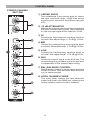
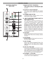
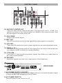
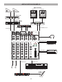
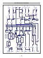
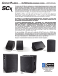
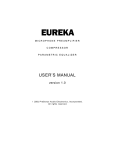
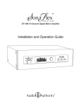
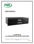
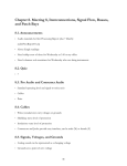
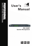
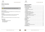
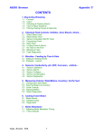
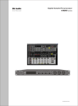
6-Channel Portable Mixer
Model: MIX-06
User Manual
www.talentaudio.com
SAFETY PRECAUTIONS
SAFETY PRECAUTIONS
WARNING - TO REDUCE THE RISK OF FIRE OR ELECTRIC SHOCK,
DO NOT EXPOSE THIS UNIT TO RAIN OR MOISTURE.
Do not allow water or liquids to be spilled into this unit. If the unit has been exposed
to rain or liquids, please unplug the power cord immediately from the outlet (with DRY
HANDS) and get a qualified service technician to check it. Keep this unit away from
heat sources such as radiators, heat registers, stoves, etc.
This unit contains no user-serviceable parts. Refer all service needs to a qualified
service technician through a Talent dealer.
This triangle on your component
alerts you to the presence of
uninsulated dangerous voltage inside
the enclosure that may be sufficient to
constitute a risk of shock.
This triangle on your component
alerts you to important operating
and maintenance instructions in
this accompanying literature.
CAUTION:
TO REDUCE THE RISK OF ELECTRIC SHOCK, DO NOT REMOVE
COVERS (OR BACK). NO USER-SERVICEABLE PARTS ARE INSIDE.
REFER ALL SERVICING TO QUALIFIED SERVICE PERSONNEL.
Keep this unit clean by using a soft dry brush and occasionally wiping it with a damp
cloth. Do not use any other solvents, which may damage the paint or plastic parts.
Regular care and inspection will be rewarded by a long product life and maximum
reliability.
Your Talent MIX-06 MINI MIXER was packed carefully at the manufacturing site,
and the packing box was designed to protect the unit from rough handling. We
recommend that you examine the packaging and its contents for any signs of physical
damage that may have occurred during transportation.
If the unit is damaged, notify your dealer and the shipping company immediately.
Claims for damage or replacement may not be granted if not reported properly or in a
timely manner.
2
INTRODUCTION
/ CONTENTS / FEATURES
INTRODUCTION
Thank you for choosing the Talent MIX-06 Mini Mixer. Its small size, handsome
appearance, and useful functionality make it a great addition to your audio
arsenal. You’ll find the compact, rugged MIX-06 easy to schlep from gig to gig,
and its operation is simple and intuitive. In order to exploit fully the MIX-06’s many
benefits, please read this manual carefully to understand all of the product’s
functions and operations.
CONTENTS
Precautions...............................................2
Introductions/Features/Contents...............3
Control panel.............................................4
Mono channel section............................4
The stereo channel.................................5
Master control section............................6-7
Application example..................................8
Specifications............................................9
System block diagram.............................10
FEATURES
• 2 mono input channels and 2 stereo input channels
• 3-band (Low, Mid, Hi) equalizer for each input channel
• Low-noise discrete mic preamp with trim control on 2 microphone inputs
• Switchable low cut filter reduces bass frequencies on mono input channels
• 2 stereo inputs with switchable 10 dB input sensitivity attenuator
• AUX input and output
• Stereo play input and record output
• Stereo monitor output and headphone output
• Peak indicator on each input channel
• Switchable +48V phantom power for condenser mics
• External power supply with locking connector
3
CONTROL PANEL
MONO CHANNEL
SECTION
1) MIC
XLR connector for microphones, input level range:
-60 to -20 dB. This connector can provide +48V
phantom power for condenser microphone when
the Phantom switch is on.
2) LINE
Balanced/unbalanced 1/4’’ phone jack for connecting
a line level source, input level range: -40 to 0 dB.
3) GAIN CONTROL
Use this knob to adjust the level of the input signal
to the optimal setting. For the best balance of S/N
ratio and dynamic range, adjust this knob so that the
peak indicator (10) lights only occasionally.
4) LOW CUT SWITCH
A low cut filter will be inserted into the channel
when this switch is pressed, thereby reducing bass
muddiness or rumble.
5) HI
Controls the high-frequency equalizer boost or cut
level. Max adjust range: +/-15 dB @ 12 KHz.
6) MID
Controls the midrange-frequency equalizer boost or
cut level. Max adjust range: +/-15 dB @ 2.5 KHz.
7) LOW
Controls the low-frequency equalizer boost or cut
level. Max adjust range: +/-15 dB @ 80 Hz.
8) AUX
Sends the channel signal to the AUX bus. The
controlled signal is pre-fader so that the aux level is
independent of the channel fader setting.
9) PAN
Distributes the channel’s stereo signal level feed to
the MAIN bus, which is a single fader that controls
the left/right stereo output. The L/R signals are equal
when the knob is in its center position.
10) PK PEAK INDICATOR
The red LED warns when an excessively high
signal level is present in the channel. The signal
is sampled in front of channel fader. It will light
approximately 3 dB before clipping and therefore
give warning of a possible overload.
11) LEVEL CHANNEL FADER
This rotary fader controls the input channel’s output
level feed to the MAIN bus, adjusting the volume
balance relative to other channels.
4
CONTROL PANEL
STEREO CHANNEL
SECTION
1) L/MONO AND R
Two unbalanced 2-pole phone jacks for stereo
line input. Input level range: -10 dB. If the source
signal is mono, connect to the L/Mono input jack
only.
2) -10 dB ATTENUATOR
Matches the output levels of sources connected to
the mixer’s stereo input sockets. When switched
on, the line input signal will be reduced -10 dB.
3) HI
Controls the high-frequency equalizer boost or
cut level. Max adjust range: +/-15 dB @ 12 KHz.
4) MID
Controls the midrange-frequency equalizer boost
or cut level. Max adjust range: +/-15 dB @ 2.5 KHz.
5) LOW
Controls the low-frequency equalizer boost or
cut level. Max adjust range: +/-15 dB @ 80 Hz.
6) AUX
Sends the channel signal to the AUX bus. The
controlled signal is pre-fader so that the aux level
is independent of the channel fader setting.
7) BAL (BALANCE) CONTROL
Distributes the channel’s stereo signal level feed
to the L/R buses. They are equal when the knob
is in its center position.
8) LEVEL CHANNEL FADER
This rotary fader controls the input channel’s
output level feed to the MAIN bus, adjusting the
volume balance relative to other channels.
5
CONTROL PANEL
MASTER CONTROL
SECTION
1) MAIN OUTPUT CONTROL
Slide fader used for adjusting the final
L/R output level sent to the MAIN output
sockets.
2) OUTPUT LEVEL METER
This level meter indicates the signal
level of the stereo MAIN output (Left and
Right).
3) POWER INDICATOR
Indicates proper working status of the
internal DC power supply.
4) +48V PHANTOM POWER SWITCH
AND INDICATOR
This switch is used for turning on or
off +48V phantom power to operate
condenser microphones. When this
switch is pressed down, +48V will be
present on the XLR socket of each
microphone input channel. PLEASE
NOTE: Minimize all channel fader levels
before turning on/off this switch. Don’t
plug or unplug microphones after this
switch is turned on (causes loud pops!).
Don’t turn on the switch when a dynamic
microphone is in use.
5) AUX RET
Controls the signal level feed to the stereo
MAIN buses from the auxiliary return
sockets.
6) AUX SEND
Master control of the signal level sent to
the AUX SEND socket.
7) 2TK TO MIX
When this switch is pressed down, the
signal from the 2TK RET input sockets
can be fed to the MAIN bus output
sockets.
8) 2TK TO CTRL RM
Press down this button to feed the 2-track
input signal (2TK RET) to the control
room and headphones (PHONES/CTRL
RM). Release it to feed the MAIN signal
to the control room and headphones.
9) PHONES / CTRL RM
6
This knob controls the signal level to the
control room and headphones.
CONTROL PANEL
10) AUX RET L/MONO & R
These are two auxiliary input phone jacks. The rated input level is -10 dB. Only
connect the output of your source device to L/MONO if the source is mono, thus
the right signal is the same as the left.
11) AUX SEND
Outputs the auxiliary signal.
12 REC OUT
Two RCA connections send left and right MAIN output signals for recording.
13) 2TK RET
These two RCA connections receive stereo signals from an external playback device.
14) MAIN ( L, R )
The MAIN 1/4" jack sockets send line level signals from the mixer to external devices
(for example: an EQ or directly to a power amplifier).
15) CTRL RM
These two 1/4" jack sockets send stereo signals from MAIN out or tape player to
the control room speakers.
16) PHONES
Sends the signals from main out or tape player to the headphone.
REAR PANEL
1) AC POWER SUPPLY SOCKET
Used for connecting an external power adapter. Be sure to connect the power supply
to the mixer BEFORE plugging into the AC outlet.
2) AC POWER SWITCH
Turns AC power to the mixer on or off.
7
APPLICATION EXAMPLE
LEFT
RIGHT
POWER AMP
POWER AMP
EFFECT PROCESSOR
AUX SEND
CTRL RM
MIC1
MIC2
2
2
1
3
ST. MAINOUT L/R
AUX RET
AUX RET
L/MONO
1
AUX
SEND
R
REC
OUT
MIX-06
Compact Mixer
3
2TK
RET
LINE1
LINE IN 3/4
LINE2
GAIN
20
60dB
GAIN
20
60dB
LINE IN 5/6
CTRL RM
PHONES
MAIN
L/MONO
L/MONO
L
L
R
R
R
R
32ohm
3mW
HEAD PHONES
REC OUT L/R
LOW
CUT
LOW
CUT
-10dB
-10dB
HI
HI
HI
HI
+10
+48V
PHANT OM
+4
6
-15
+15
-15
+15
MID
-15
+15
MID
-15
12
+15
MID
MID
18
AUX
RET
-15
+15
-15
+15
LOW
-15
+15
LOW
-15
+15
LOW
1
10
1
10
L
R
INDICA TOR
LOW
10
AUX
SEND
-15
+15
-15
+15
AUX
-15
+15
AUX
-15
+15
AUX
5
AUX
2TK RET
0dB
10
1
10
1
PK
10
1
1
10
2TK
TO MIX
R
2TK T O
CTRL RM
PK
5
10
L
PAN
R
L
PAN
R
L
BAL
R
L
BAL
15
20
30
50
1
LEVEL
10
1
MIC IN
1
LEVEL
2
10
1
LEVEL
3 4
10
1
LEVEL
5 6
10
1
10
PHONES/CTRL
RM
MAIN
MAIN SECTION
LINE IN L/R
LINE IN L/R
8
CD PLAYER
SPECIFICATIONS
Input
Impedance
Rated
Input level
2 TRS
2 RCA
2 TRS
2K ohm
47K ohm
10K ohm
10K ohm
10K ohm
-60 dB
-40 dB
-10 dB
-10 dB
-10 dB
Connector
2 TRS
2 TRS
TRS
2 RCA
3-pole TRS
Outputs
Impedance
75 ohm
75 ohm
75 ohm
1K ohm
75 ohm
Inputs
Microphones
Mono LINE IN
Stereo LINE IN
Stereo PLAY IN
Stereo AUX RET
Number
Input modes
Connector
2
2
2
1
1
Balanced
Balanced
Unbalanced
Unbalanced
Unbalanced
XLR
3-pole TRS
Outputs
Stereo MAIN OUT
CTRL RM
AUX SEND
Stereo REC OUT
HEADPHONE
Number
1
1
1
1
1
Outputs modes
Unbalanced
Unbalanced
Unbalanced
Unbalanced
Unbalanced
Max gain
72 dB
78 dB
62 dB
55 dB
22 dB
22 dB
19 dB
19 dB
Signal route
MIC IN------MAIN L/R, AUX SEND
MIC IN------CTRL RM OUT L/R
MIC IN------REC OUT
MONO LINE IN------MAIN OUT L/R
ST. LINE IN------MAIN OUT L/R
AUX RET------MAIN OUT L/R
2TK RET------MAIN OUT L/R
2TK RET------CTRL RM OUT L/R
Channel EQ
Low cut filter
Total harmonic distortion
Frequency response
Max out level
Microphone preamp E.I.N
Power
Power consumption
Weight (includes power adapter)
Dimensions
Rated
Output level
+4 dB
+4 dB
+4 dB
-10 dB
3 mW @ 36 ohm
Conditions
@ 620 ohm Load
@ 620 ohm Load
@ 10K ohm Load
@ 620 ohm Load
@ 620 ohm Load
@ 620 ohm Load
@ 620 ohm Load
@ 620 ohm Load
HI 12K Hz MID 2.5K Hz LOW 80 Hz max equalizing value +/-15 dB
80 Hz 18 dB/OCT
<0.1% @ +14 dB 20~20000 Hz 620 ohm load
+1/-2 dB @ +4 dB 20~20000 Hz 620 ohm load
+20 dB @ 0.5%THD 1K Hz 620 ohm load
-124 dB @ 150 ohm, at max gain
120 VAC, 60 Hz
5W
1.8Kg
7-7/8" W x 2" H x 9" D
9
10
2TK RET
R
AUX RET
L /MONO
R
LINE IN
L /MONO
LINE IN
MIC IN
-20dB
-10dB
GAIN
LOW
EQ
MID
EQ
LO CUT
HI
LEVEL
LEVEL
2TK TO MIX
AUX RET
HI
PEAK
EQ
MID
CH INDICAT
LOW
PAN
AUX
PAN
AUX
L R AUX
L R AUX
VU
5LED
2TK TO
CTRL RM
5LED
VU
MAIN
PHONES/
CTRL ROOM
AUX SEND
PHONES
CTRL RM R
CTRL RM L
REC OUT
MAIN L OUT
AUX SEND
SYSTEM BLOCK DIAGRAM
WARRANTY
We at Talent are dedicated to providing our customers with professional, high
quality stage and studio accessories. As such, all Talent products are warranted
free from defects in material and workmanship for a period of One Year from
the date of purchase.
Warranty registration is not required, but purchasers are asked to retain their
receipt as proof of purchase. Warranty does not apply to misuse, abuse,
neglect, accident, improper use, etc.
For complete customer satisfaction, Talent resellers are asked to act as
agents for the purpose of handling warranty claims. Please return your Talent
product to your place of purchase prepaid. Many Talent resellers require a
return authorization (also known as an RA or RMA). Please contact your Talent
reseller for more details.
11