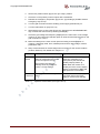
1
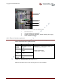
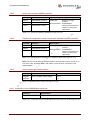
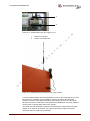
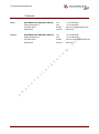
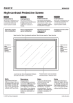
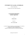
Copyright WOODWARD IDS
Installation and User Manual
p
h
o
t
o
v
o
l
t
a
i
k
f
o
r
u
m
.
c
o
m
for the SOLO 500 Photovoltaic Inverter
Version 2.01
p
h
o
t
o
v
o
l
t
a
i
k
f
o
r
u
m
.
c
o
m
Copyright WOODWARD IDS
Contents
2
3
o
v
o
l
t
a
i
k
f
o
r
u
m
.
c
o
4
Introduction ........................................................................................................... 5
1.1 Disclaimer ..................................................................................................... 5
1.2 IMPORTANT SAFETY INSTRUCTIONS ..................................................... 5
1.3 Scope of Delivery ......................................................................................... 6
1.4 Type Label .................................................................................................... 6
Warnings and Notes ............................................................................................. 7
Transporting the Inverter ..................................................................................... 8
3.1 Transport by Crane ...................................................................................... 8
3.2 Transport by Forklift ..................................................................................... 9
Installation of the Inverter .................................................................................. 10
4.1 Location Selection ...................................................................................... 10
4.2 Mechanical Installation ............................................................................... 11
4.3 Foundation ................................................................................................. 12
4.4 Installing the Heat Exchanger .................................................................... 13
4.5 Connecting the Heat Exchanger to the Inverter ......................................... 14
4.6 Electrical Installation ................................................................................... 17
4.6.1
Overview of the Electrical Connections ...................................... 17
4.6.2
Schematic Example of a SOLO System ..................................... 18
4.6.3
Power Connections ..................................................................... 19
4.6.4
Transformer Specification ........................................................... 21
4.6.5
Auxiliary Power Connection ........................................................ 22
4.6.6
Installation of the Heat Exchanger Fan ....................................... 23
4.6.7
Installation of the Transformer Monitoring .................................. 24
4.6.8
Installation of the External Grid Monitoring ................................. 24
4.6.9
External Start/Stop Command .................................................... 24
4.6.10 External Emergency Stop ........................................................... 25
4.6.11 Digital Interface Specification ..................................................... 25
4.6.12 Active String Boxes with Contactors (optional) ........................... 26
4.6.13 Power Limitation (optional) ......................................................... 29
4.6.14 Serial user interface RS485 (optional) ........................................ 30
4.6.15 Interface to Integrated Central Control unit / Weather station
(optional) ..................................................................................... 30
4.6.16 Power supply for weather station ................................................ 30
4.6.17 Installation of the GSM Modem (optional) .................................. 30
4.6.18 Ethernet connection .................................................................... 32
Commissioning ................................................................................................... 33
5.1 Refilling and Bleeding the Cooling Circuit .................................................. 33
5.2 Inverter Commissioning.............................................................................. 35
5.2.1
Control and Visualisation Elements ............................................ 35
5.2.2
Important Components Overview ............................................... 36
5.2.3
Initialisation ................................................................................. 36
5.2.4
Commissioning of the Power Section ......................................... 38
5.3 Operation .................................................................................................... 38
5.3.1
Turning the Inverter On ............................................................... 38
5.3.2
Turning the Inverter Off ............................................................... 39
Maintenance ........................................................................................................ 40
6.1 Maintenance of the SOLO Inverter ............................................................ 40
6.2 Maintenance of the Cooling Circuit ............................................................ 40
Operating the Touch Screen Panel of the Inverter and Parameterization .... 41
7.1 Main Menu .................................................................................................. 41
7.2 Submenus .................................................................................................. 42
7.3 Parameter Changes ................................................................................... 42
7.4 Access Rights to Functions and Parameters ............................................. 43
7.5 Inverter Parameter List ............................................................................... 44
7.6 Ethernet setup for Remote Diagnostic ....................................................... 46
7.7 String Monitoring ........................................................................................ 46
m
1
p
h
o
t
5
6
7
WOODWARD IDS
3/54
IUM SOLO500 EN V2.01 1211
Copyright WOODWARD IDS
7.8 Events Log ................................................................................................. 48
Diagnostics and Troubleshooting .................................................................... 49
EC – Declaration of Conformity ........................................................................ 51
Data Sheet SOLO 500 ......................................................................................... 52
p
h
o
t
o
v
o
l
t
a
i
k
f
o
r
u
m
.
c
o
m
8
9
10
WOODWARD IDS
4/54
IUM SOLO500 EN V2.01 1211
Copyright WOODWARD IDS
1
Introduction
This high-quality WOODWARD IDS photovoltaic inverter is intended for feeding
photovoltaic energy into the public grid with a very high efficiency. Through the liquid
cooling of the inverter heat is taken out efficiently from the operating room.
1.1
Disclaimer
c
o
m
WOODWARD IDS delivers optimized tested equipment such as inverters and
string boxes for Photovoltaic Power Plants. The correct integration and
interconnection of the equipment must be made according to the manuals and
datasheets of WOODWARD IDS and is responsibility of the System Integrator.
WOODWARD IDS does not accept liability for system design, dimensioning of
system related parts, installation or the performance of the system. Claims due
to product breakdowns are excluded.
o
r
u
m
.
The content of this manual is regularly reviewed for compliance with the hardware and
software operation and any corrections are included in later editions. Every effort is
made to ensure the details in this manual are accurate. Warranty claims will not be
accepted in case of violation of the installation instructions and we do not accept
liability in case of accidents caused by inappropriate handling or work performed by
unauthorized personnel which results in personal injury or damage to devices, or any
other subsequent damages.
IMPORTANT SAFETY INSTRUCTIONS
k
f
1.2
i
READ AND SAVE THESE INSTRUCTIONS!
a
This manual contains important safety and operating instructions for SOLO 500
photovoltaic inverter. Keep it with or near the inverter at all times.
p
h
o
t
o
v
o
l
t
Photovoltaic installations operate with lethal voltages and the work described here
should only be performed by authorized personnel familiar with the installation,
mounting, commissioning, and the operation of PV installations. This manual must be
fully read and understood before installing or commissioning is performed. The SOLO
product must only be used for its intended purpose and unauthorized personnel are
not allowed to open the SOLO product. The faultless and safe operation of the product
assumes appropriate transport, specialized storage, installation and mounting as well
as correct operation and maintenance. The relevant regional and country-specific
regulations and instructions must be obeyed as well as requirements described in this
document including placement and installation instructions (e.g. connection profiles,
torque settings, etc.)
Symbols and warning signs used:
WARNING
WARNING indicates a hazardous situation which, if not avoided, could result in death
or serious injury.
NOTICE
NOTICE is used to address practices not related to personal injury. Failure to observe
could lead to property damage.
WOODWARD IDS
5/54
IUM SOLO500 EN V2.01 1211
Copyright WOODWARD IDS
Scope of Delivery
Article
1 pcs
SOLO 500 PV Inverter, cooling system filled with liquid 1 bar pressure
1 pcs
Cabinet key
1 pcs
Heat exchanger filled with liquid 0 bar pressure with wall mountings and
connection box
1 pcs
Hand pump for filling liquid in the cooling system
2 x 10 m
Hose (outer diameter 37 mm) with pipe union (shorter hoses on request)
12 m
Power supply cable for the fan of the heat exchanger
10 pcs
Quick fastener buckle 37 mm for hose mounting
2m
Hose (outer diameter 10 mm) for liquid drain outlet (see Figure 4.5-7)
3 litre
Coolant (45% ethylene-glycol) in the hand pump
c
o
m
Quantity
Scope of delivery
u
Table 1.1
m
.
1.3
r
Type Label
o
1.4
1
2
p
h
o
t
o
v
o
l
t
a
i
k
f
The type label with the product identification is located at the top right corner on the
inner side of the right cabinet door.
2
Figure 1.1
SOLO 500 type label
1
2
3
WOODWARD IDS
Product identification
Valid electrical circuit diagram
Serial number of the inverter
6/54
IUM SOLO500 EN V2.01 1211
Copyright WOODWARD IDS
2
Warnings and Notes
WARNING
The local installation standards must be obeyed.
WARNING
o
m
The device must only be installed, operated and maintained by qualified personnel.
c
WARNING
u
m
.
The device carries lethal grid and PV generator voltages. Consider a capacitor
discharge time of 10 minutes! And beware that an automatic restart can follow a grid
or photovoltaic voltage failure.
o
r
WARNING
k
f
Consider all safety instructions displayed on the inverter and in the installation and
user manual!
a
i
WARNING
v
NOTICE
o
l
t
If any information is unclear, please refer to WOODWARD IDS Service Centre!
Loss of warranty!
p
h
o
t
o
The cabinet must not be damaged and no holes are allowed to be drilled in the
cabinet. Any transport damages must be reported to Woodward IDS.
WOODWARD IDS
7/54
IUM SOLO500 EN V2.01 1211
Copyright WOODWARD IDS
3
Transporting the Inverter
In order to avoid transport damage, the following points must be strictly obeyed:
3.1
1.
The SOLO inverter must always be stored and transported in a vertical position.
2.
The SOLO inverter cabinet can be transported by crane using pallet forks or by a
forklift.
Transport by Crane
m
WARNING
.
c
o
If the inverter falls during lifting, persons in the vicinity could be crushed resulting in
death or serious injury. Make sure that no persons are in the danger area around the
lifted inverter. Observe the relevant regulations for crane operation.
Figure 3.1
Pallet forks
p
h
o
t
o
v
o
l
t
a
i
k
f
o
r
u
m
The cabinet is lifted only by pallet forks.
WOODWARD IDS
8/54
IUM SOLO500 EN V2.01 1211
Copyright WOODWARD IDS
3.2
Transport by Forklift
WARNING
If the inverter tilts over during the transport, people in the vicinity could be crushed
resulting in death or serious injury. Ensure that no people are in the danger area
around the lifted inverter.
Forklift transportation using side openings
p
h
o
t
o
v
o
l
t
a
i
k
Figure 3.2
f
o
r
u
m
.
c
o
m
Note: The front and back covers of the socket must be removed for the transport (see
Figure 3.2 and Figure 3.3).
WOODWARD IDS
Figure 3.3
Forklift transportation using front openings
9/54
IUM SOLO500 EN V2.01 1211
Copyright WOODWARD IDS
4
Installation of the Inverter
Upper connection
Heat exchanger
SOLO 500
Heat exchanger
power supply
GSM antenna
Lower connection
←
Intlet
→
Control signals
m
PV module
Outlet
String box
o
Communication
Control / SPS
c
Ethernet
IP - grid
PV module
m
.
PV input 1
Modem connection
Telephone grid
r
u
String box
Grid power feed-in
(IT grid system)
f
o
PV input 2
PV module
k
String box
Auxiliary power
supply
i
Communication
l
t
a
PV input 3
v
o
Figure 4.1 Example view of a photovoltaic installation with SOLO inverter, SOLO
string boxes and grid transformer
Location Selection
p
h
o
t
o
4.1
The inverter cabinet is intended for indoor operation.
The inverter should be positioned as close as possible to the transformer (< 5 m).
The place must meet the requirements for installation of electrical operation
devices and must be ventilated. The heat output of the components that are not
directly liquid cooled is up to 7000 W at maximum power.
To avoid additional heating, a location without direct sun irradiation should be
chosen.
The cabinet must be easily accessible for operation and maintenance.
The operating elements (main switch, emergency stop button, Start/Stop switch)
are mounted outside the cabinet and should be protected from unauthorized
manipulation.
Assure a dust-free environment to prevent filter clogging and malfunction of the
inverter cooling system. In rooms with high pollution the air filters have to be
checked in shorter intervals.
Make sure that the minimum required clearances to surrounding objects are
respected (emergency exit route, maintenance works, air cooling, etc.) – see
Figure 4.2.
WOODWARD IDS
10/54
IUM SOLO500 EN V2.01 1211
Copyright WOODWARD IDS
4.2
Mechanical Installation
The requirements are listed in Table 4.1. The inverter must be installed on a firm,
horizontal surface with the sufficient load-carrying capacity. The inverter can be
mounted on a foundation or on a grounded metal frame. No liquid (water, oil, coolant,
etc.) should ever enter into the cabinet, not even during installation.
Item
Requirement
Minimum size of the foundation SOLO 500 (W x D)
1200 x 800 mm
Maximum inclination of the foundation
+/- 5 mm
Load-carrying capacity of the foundation
> 1500 kg / m
m
300 mm
from the cabinet left side
100 mm
from the cabinet right side
500 mm
m
.
c
from the cabinet rear side
o
Minimum clearance:
from the cabinet front side
u
above the cabinet roof
300 mm
1400 x 2100 mm
l
t
> 300 mm
Rear side
a
i
k
f
Mechanical requirements
1000 mm
o
r
Entrance opening (W x H)
Table 4.1
2
> 500 mm
o
> 100 mm
t
o
v
SOLO cabinet
1200 x 800 x 1920
p
h
o
Front
Door
Door
> 1000 mm
Room height > 2300 mm
> 1400 mm
Figure 4.2
Minimum clearances
Note: Alternative placement of the SOLO inverter only after consultation with
WOODWARD IDS.
WOODWARD IDS
11/54
IUM SOLO500 EN V2.01 1211
Copyright WOODWARD IDS
Foundation
r
u
m
.
c
o
m
4.3
o
Aux, Control,
Transformer
PV1, PV2, PV3
f
Openings in foundation for cables
k
Foundation
p
h
o
t
o
v
o
l
t
a
i
Figure 4.3
WOODWARD IDS
12/54
IUM SOLO500 EN V2.01 1211
Copyright WOODWARD IDS
4.4
Installing the Heat Exchanger
WARNING
The heat exchanger must be mounted using fixing steel bolts or screws type M10.
The heat exchanger [Figure 4.4-2] should be mounted outdoors on a solid wall, in a
place with no direct sun irradiation. The elevation of the top level of the heat
exchanger must be less than 9 m above the bottom level of the inverter.
1
m
.
c
o
m
The alignment should be executed as shown in Figure 4.4, with the bleeding valve
[Figure 4.4-1] at the highest point of the cooling system.
2
3
i
k
f
o
r
u
7
4
t
a
6
o
v
o
l
5
p
h
o
t
Figure 4.4
WOODWARD IDS
Connection of the cooling system
1
2
3
4
5
6
7
Bleeding valve
Heat exchanger with fan
Coolant hose to the inverter inlet
Coolant hose to the inverter outlet
Fan power supply cable
SOLO inverter cabinet
Wall mountings of the heat exchanger
13/54
IUM SOLO500 EN V2.01 1211
Copyright WOODWARD IDS
4.5
Connecting the Heat Exchanger to the Inverter
NOTICE
c
o
m
At delivery, all tubes in the cabinet and the hoses of the heat exchanger are filled with
coolant and the entrapped air is bleeded (purged).
The inlet and outlet hoses must not be interchanged!
1
2
f
o
r
u
m
.
8
3
k
7
i
6
a
4
o
l
t
5
p
h
o
t
o
WOODWARD IDS
Cooling system elements and pipe connections on the inverter
v
Figure 4.5
1
2
3
4
5
6
7
8
Filling connection
Filling valve
Outlet valve
Hose connection inverter outlet
Hose connection inverter inlet
Inlet valve
Liquid drain outlet (for maintenance)
Manometer
14/54
IUM SOLO500 EN V2.01 1211
Copyright WOODWARD IDS
3
1
2
o
Union connection
Gasket
Valve handle
Filling valve (see Figure 4.5-2)
p
h
o
t
o
v
o
l
t
Figure 4.7
a
i
k
f
o
r
u
m
.
1
2
3
m
Hose connection (inlet/outlet)
c
Figure 4.6
Figure 4.8
Valve with locking screw (see Figure 4.5-3,-6)
Please follow the sequence below to connect the heat exchanger to the inverter:
WOODWARD IDS
1.
Connect the hose [Figure 4.4-3] from the upper connection of the heat exchanger
(the right hose of the front view of the heat exchanger) to the inverter inlet [Figure
4.5-5] using the gasket [Figure 4.6-2].
2.
Connect the hose [Figure 4.4-4] from the lower connection of the heat exchanger
(the left hose of the front view of the heat exchanger) to the inverter outlet [Figure
4.5-4] using the gasket [Figure 4.6-2].
3.
Mount the handles [Figure 4.6-3] on the hose valves [Figure 4.6].
4.
Remove the locking screws from handles of inverter inlet and outlet [Figure 4.8].
15/54
IUM SOLO500 EN V2.01 1211
Copyright WOODWARD IDS
5.
Open the four valves - on the inverter inlet and outlet connections [Figure 4.5-3, 6] and on the inlet and outlet hoses [Figure 4.6] (counter-clockwise).
6.
Connect the power supply cable [Figure 4.4-5] of the fan to the inverter [Table
4.7].
Requirement
Maximum hose length (inverter – heat exchanger)
10 m
Maximum elevation above inverter level (inverter bottom level
to heat exchanger top level)
9m
Pressure (air pressure) in the 8 litre expansion vessel
(at 20 °C and when no pressure in the liquid)
0.5 bar
Nominal pressure in the cooling system at 20 °C
2.0 bar
Minimum pressure in the cooling system (negative pressure
fault) at 20 °C
1.1 bar
.
c
o
m
Item
m
Integrated safety valve
u
Antifreeze
Coolant concentration (for freezing point: -25 °C)
3.5 bar
Ethylene-glycol
45% antifreeze,
o
r
55% water
Coolant (antifreeze-water mixture) volume
Approx. 20 litres
Heat exchanger installation requirements
p
h
o
t
o
v
o
l
t
a
i
Table 4.2
k
f
(inverter with original heat exchanger and 2 x 10 m hoses)
WOODWARD IDS
16/54
IUM SOLO500 EN V2.01 1211
Copyright WOODWARD IDS
4.6
Electrical Installation
WARNING
The installation of the inverter must only be performed by authorized personnel. The
absence of voltages (grid and PV lines) must be ensured at all times. After opening all
power connections (grid and PV) wait for 10 minutes to ensure internal power
capacitors have discharged.
Overview of the Electrical Connections
m
4.6.1
r
u
m
.
c
o
The location of the electrical connections in the inverter is shown in Figure 4.9.
o
6
k
f
5
1
2
p
h
o
t
o
3
v
o
l
t
a
i
4
Figure 4.9
Location of the electrical connections in the inverter
1
2
3
4
5
6
WOODWARD IDS
PV input power terminals
PE – copper rail for all internal and external PE connections
Power connections to the grid transformer
String box supplies, controls and feedbacks
Auxiliary power supply, heat exchanger fan supply, transformer
monitoring, external grid monitoring, external Start/Stop,
external E-stop
Fibre optic communication interface, terminal for Ethernet,
extensions for additional string boxes
17/54
IUM SOLO500 EN V2.01 1211
Copyright WOODWARD IDS
Schematic Example of a SOLO System
L1
L2
L3
N
PE
20kV
Auxiliary supply
4.6.2
.
L1
L2
L3
m
3x400VAC
3x330VAC IT grid
u
10X2/3
10X2/4
10X2/1
10X2/2
DC+
DCTx
Rx
50F4
50X8/4
50X16/3
50X16/4
10X2+
10X2-
10X2/3
10X2/4
10X2/1
49X10
10X2/2
49X9
DC+
49X8
DC-
p
Tx
Rx
Heat
exchanger
Weather
station
50F3
50X6/4
50X15/3
50X15/4
10X2+
10X2485/B
485/A
24V
0V
49X10/1
49X9/1
49X8/1
49X12/1
49X13/1
10X2/3
10X2/4
10X2/1
10X2/2
DC+
DCTx
Rx
50F2
50X4/4
50X14/3
50X14/4
10X1+
10X1-
10X2/3
10X2/4
10X2/1
10X2/2
DC+
DCTx
Rx
PE
L1
L2
L3
50F1
50X2/4
50X13/3
50X13/4
10X1+
10X1-
48X4/4
48X1/4
48X2/4
48X3/4
10X2/3
10X2/4
10X2/1
49X10
10X2/2
49X9
DC+
49X8
DC-
SSB6
Note: PE connections are not shown on the circuit diagram.
SOLO 500
49A1
50F5
50X10/4
50X17/3
50X17/4
10X3+
10X3-
SSB5
o
t
o
v
Tx
Rx
h
o
Ethernet connection
10X2/3
10X2/4
10X2/1
10X2/2
DC+
DC-
SSB4
l
Power limitation command 60%
Power limitation command 100%
o
50F6
50X12/4
50X18/3
50X18/4
10X3+
10X3-
SSB3
Power limitation command 30%
Tx
Rx
SSB2
a
Rx
Tx
61X4/3
61X4/4
61X3/3
61X3/4
61X2/3
61X2/4
61X1/3
61X1/4
t
Power limitation command 0%
25F1
25F2
25F3
25X6/4
PE
SSB1
i
Start/Stop command
12F1/2
12F1/4
12F1/6
f
49X2/4
49X2/3
49X1/4
49X1/3
49X11/4
49X11/3
E-stop feedback
E-stop command
Transformer
r
Transformer standby
49X3/3
49X3/4
48X5/3
48X5/4
49X6/1
49X5/1
49X4/1
k
Grid operator interface
485/GND
485/B
485/A
Transformer feedback
c
o
20kV
m
Switchgear
Figure 4.10 Schematic example of a SOLO system
WOODWARD IDS
18/54
IUM SOLO500 EN V2.01 1211
Copyright WOODWARD IDS
The SOLO inverter can be connected to several external devices. Most of them are
shown on Figure 4.10:
WOODWARD IDS active string boxes with contactors
Transformer with feedback signal
Emergency stop circuit
Grid operator interface – Inverter control (start/stop, power limitation)
GSM or line modem for monitoring
Ethernet for monitoring
ICC – Integrated Central Control unit
Power Connections
o
4.6.3
m
Weather station
.
c
WARNING
m
Potentially lethal voltage!
r
u
Even if the main switch is turned off the AC and PV power terminals and the auxiliary
supply might be under lethal voltage! After complete separation from the grid and from
the PV generator, wait 10 minutes before opening the door and removing the
protection cover.
f
o
Failure to observe this warning could result in death or serious injury.
i
k
NOTICE
t
a
Respect the correct PV polarity. Wrong polarity of the PV inputs can cause a short
circuit of the PV panels. Never connect the different inverter PV inputs in parallel.
o
l
Note: When planning and installing the photovoltaic plant, a uniform distribution of the
installed power onto the three PV inputs of the inverter must be ensured. See the
maximum PV input current in the datasheet.
o
v
The power connection has to be done according to Table 4.3 and Table 4.4.
Each PV input copper bar has three
conductor clamps for one cable.
10X3+
PV input 3 (positive pole)
10X2-
PV input 2 (negative pole)
10X2+
PV input 2 (positive pole)
10X1-
PV input 1 (negative pole)
10X1+
PV input 1 (positive pole)
o
h
Specifications
PV input 3 (negative pole)
10X3-
p
Function
t
Terminal
Table 4.3
Fastening torque:
12…15 Nm
2
Cu-cross section:
70…150 mm
Note: Follow the National Electrical
Code
PV input power connections (see Figure 4.11)
Note: For convenience please connect the cables in the sequence shown in Table 4.3.
WOODWARD IDS
19/54
IUM SOLO500 EN V2.01 1211
Copyright WOODWARD IDS
10X1+
10X1-
10X2+
o
m
10X2-
f
o
r
u
m
.
c
10X3+
+
10X3+
k
Figure 4.11 PV input power terminals (see also Figure 4.9-1)
Terminal
L1
12F1 – terminal 2
L2
12F1 – terminal 4
L3
12F1 – terminal 6
v
o
l
t
a
i
Connection
Specifications
Each phase terminal copper bar has two
screws for two cables.
Connection type:
M12
Cable lug width:
max. 38 mm
Fastening torque:
43 Nm
2
t
o
Copper cross section: 2 x 120 … 240 mm
Note: Follow the National Electrical Code
Phase connections to the grid transformer (see Figure 4.12)
p
h
o
Table 4.4
Figure 4.12 Phase terminals (see also Figure 4.9-3)
WOODWARD IDS
20/54
IUM SOLO500 EN V2.01 1211
Copyright WOODWARD IDS
Connection
Terminal
Specifications
Protection
earth (PE)
PE – copper rail
Connection type:
M10
Fastening torque:
25 Nm
Copper cross section:
240 mm
Protection earth connection to the grid transformer (see Figure 4.13)
i
k
f
o
r
u
m
.
c
o
m
Table 4.5
2
l
t
a
Figure 4.13 PE – copper rail (see also Figure 4.9-2)
Transformer Specification
v
o
4.6.4
o
NOTICE
o
t
The SOLO inverter must not be connected directly to grid. An external transformer is
required.
p
h
Transformer specification:
Rated power: 500 kVA
Rated voltage at inverter side: 330 V (or 300 V when the relevant option is used)
Neutral not grounded if the star point of the transformer is on the inverter side.
A grounded screen is mandatory between primary and secondary windings.
Several inverters can be connected to a common transformer, but a separate
secondary winding set is needed for each inverter (floating, IT grid).
WOODWARD IDS
21/54
IUM SOLO500 EN V2.01 1211
Copyright WOODWARD IDS
4.6.5
Auxiliary Power Connection
NOTICE
The connection points of user contact spring-cage terminals (Chapters 4.6.5 to 4.6.16)
are opened with a standard screwdriver.
After the conductor has been inserted into the terminal compartment, the screwdriver
is removed and the conductor automatically makes contact.
c
o
m
The auxiliary power supply 400 V, 50 / 60 Hz can be implemented as internal (default)
or as external power supply. When the internal auxiliary supply connection is used
then the supply of the inverter control is connected internally through the main switch
to the power connections L1, L2, L3 (see Table 4.4).
p
h
o
t
o
v
o
l
t
a
i
k
f
o
r
u
m
.
Note: The inverter is delivered with wire bridges 25X1/4 – 25F1, 25X2/4 – 25F2,
25X3/4 – 25F3, 25X4/4 – 25X6/4 connected (internal auxiliary power supply by
default, see Figure 4.14).
Figure 4.14 Wire bridges for internal auxiliary power supply (see also Figure 4.9-5)
External power supply 400 V grid is recommended where a low tariff grid power
supply is available (see Table 4.6).
Note: For external auxiliary supply, remove the bridges for internal supply 25X1/4 –
25F1, 25X2/4 – 25F2, 25X3/4 – 25F3, 25X4/4 – 25X6/4 (see Figure 4.14), and
execute the following connections:
WOODWARD IDS
22/54
IUM SOLO500 EN V2.01 1211
Copyright WOODWARD IDS
Terminal
Function
Connection type
Cu-cross section
External supply
configuration
connect to:
PE
PE
Spring-cage
1.5...2.5 mm
2
25F1
Input L1
Spring-cage
1.5...2.5 mm
2
External grid L1
1.5...2.5 mm
2
External grid L2
External grid L3
External grid N
25F2
Input L2
Spring-cage
25F3
Input L3
Spring-cage
1.5...2.5 mm
2
25X6/4
Input N
Spring-cage
1.5...2.5 mm
2
m
External auxiliary power supply
o
Table 4.6
PE
Installation of the Heat Exchanger Fan
r
u
4.6.6
m
.
c
Note: Never supply the inverter from a source controlled by "Transformer standby
output signal" (see Table 4.8) because it will not be able to recover after signal
activation.
Function
48X1/4
Fan power supply – Output L1
48X2/4
Fan power supply – Output L2
48X3/4
Fan power supply – Output L3
48X4/4
PE
Specifications
400 VAC / max. 0.6 A
400 VAC / max. 0.6 A
400 VAC / max. 0.6 A
i
k
f
o
Terminal
a
t
Heat exchanger fan connection (Figure 4.15)
p
h
o
t
o
v
o
l
Table 4.7
PE
Figure 4.15 Heat exchanger fan supply, transformer monitoring, external grid
monitoring, external Start/Stop, external E-stop (see also Figure 4.9-5)
WOODWARD IDS
23/54
IUM SOLO500 EN V2.01 1211
Copyright WOODWARD IDS
Installation of the Transformer Monitoring
Terminal
Function
Specification
48X5/3
Transformer ready signal (e.g.
from an automatic safety device
in the transformer cabinet)
Digital input – connect a wire
bridge if not used
48X5/4
49X3/3
Transformer standby signal
ready
Contact open :
error
Digital output:
49X3/4
Contact closed:
in operation
Contact open:
standby
Signal connections of the grid transformer monitoring (see Figure 4.15)
c
o
Table 4.8
Contact closed:
m
4.6.7
Installation of the External Grid Monitoring
o
r
4.6.8
u
m
.
Note: Transformer standby is used if an electrically controllable switch gear is
connected between the transformer and the grid
Function
Specification
61X6/3
Feedback – input to main control
module of inverter in case of grid
fault
k
f
Terminal
t
a
i
61X6/4
Main contactor control – hardware
deactivation of the inverter’s main
contactor in case of grid fault
l
61X5/3
v
o
61X5/4
Digital input – connect a wire
bridge if not used
Contact closed:
no error
Contact open :
error
Digital input – connect a wire
bridge if not used
Contact closed:
in operation
Contact open:
E-stop
o
t
o
Table 4.9 Signal connections for external grid monitoring (see Figure 4.15)
External Start/Stop Command
p
h
4.6.9
External Start/Stop command has the same function as the two-position switch
Start/Stop [Figure 5.2-2]
Terminal
Function
Specification
49X11/3
External Start/Stop input
Digital input – connect a wire
bridge if not used
49X11/4
Contact closed:
“Start” position
Contact open:
“Stop” position
Table 4.10 External Start/Stop (see Figure 4.15)
WOODWARD IDS
24/54
IUM SOLO500 EN V2.01 1211
Copyright WOODWARD IDS
4.6.10 External Emergency Stop
WARNING
In case there is an external emergency stop circuit it must be interposed to the
emergency stop circuit of the inverter through the corresponding terminals: The bridge
49X1/3 - 49X1/4 has to be removed and replaced by the connection to the client’s
potential free contact for emergency shut-down. The activation of the emergency stop
leads to deactivation of the inverter’s power connections, the control continues to
operate.
m
Failure to observe this warning could result in death or serious injury.
Function
Specification
49X1/3
Emergency stop (E-stop)
Digital input – connect a wire
bridge if not used
c
o
Terminal
Contact closed:
E-stop inactive
Contact open:
Е-stop active
m
.
49X1/4
Signalization:
Emergency stop (E-stop)
Digital output
Contact closed: E-stop inactive
Contact open:
Е-stop active
o
r
49X2/4
u
49X2/3
i
k
f
Table 4.11 Inverter control (see Figure 4.15)
t
a
4.6.11 Digital Interface Specification
Function
Digital
input
Reads logic level
o
Contact open
v
Active
l
Terminal
o
t
o
Inactive Contact closed
h
Active
Connect to
24 V relay
Potential free contact
Inverter
Contact open
min. 24 VDC
min. 20 mA
+24V
0V
Cu-cross section: 0.5..2.5 mm
Cable gland:
Drive logic level
p
Digital
output
Terminal specification
2
Ø 4.5-10mm
Potential free contact
24 V relay
min 10mA
Inverter
Inactive Contact closed
max 1 A
+24V
0V
Insulation voltage: 2.5 kVAC, 1 min
Cu-cross section: 0.5..2.5 mm
Cable gland:
2
Ø 4.5-10mm
Table 4.12 Digital interface specification
WOODWARD IDS
25/54
IUM SOLO500 EN V2.01 1211
Copyright WOODWARD IDS
4.6.12 Active String Boxes with Contactors (optional)
The total number of string boxes is limited to 9 pcs SSB or 12 psc ISB. (2-3 psc SSB
or 2-4 pcs ISB on each tracker input).
WOODWARD IDS offers string boxes with contactors. The contactor type string boxes
are controlled by the SOLO inverter and must be connected according to Table 4.13
and Table 4.14. The feedback is used by all SOLO string box types (see Table 4.14).
In order to prevent cable overheating in case of reverse current, when have more than
2 string boxes per input fuses have to be put on PV+/PV- cables from boxes. The
fuses must be 150A for 14-input box and 250A for 25-input box.
o
m
Stand-by mode: The wake-up signal for stand-by mode of the inverter is related to
PV input 1. Therefore this PV input must always be connected to a PV-field in order to
make sure the SOLO will start while standby-mode is active.
.
c
For contactor string box installation make sure, that one string box (called "overnight
string box") is controlled separately (see Table 4.14).
Specification
50F1/1
String Box 1 (overnight string box)
50X2/4
Contactor control
50F2/1
String Box 2
50X4/4
Contactor control
50F3/1
String Box 3
50X6/4
Contactor control
50F4/1
String Box 4
50X8/4
Contactor control
50F5/1
String Box 5
50X10/4
Contactor control
50F6/1
String Box 6
50X12/4
Contactor control
m
Function
Inactive: 0 V (contact open)
Active:
250 VAC/DC max. 1 A
o
v
o
l
t
a
i
k
f
o
r
u
Terminal
t
Table 4.13 String box supplies and controls (see Figure 4.16)
p
h
o
Note: String box 1 (overnight string box) has an additional function in standby mode of
the inverter during the night. The PV output power cables from this box have to be
connected to PV input 1.
WOODWARD IDS
Note: For using more than six string boxes, two string boxes can be connected in
parallel to one contactor control terminal.
26/54
IUM SOLO500 EN V2.01 1211
Copyright WOODWARD IDS
o
l
t
a
i
k
f
o
r
u
m
.
c
o
m
2
p
h
o
t
o
v
1
Figure 4.16 String boxes control
1
2
WOODWARD IDS
String box supplies, controls and feedbacks (see also Figure 4.9-4)
Extensions 1 to 6 (for additional string boxes) (see also Figure 4.9-6)
27/54
IUM SOLO500 EN V2.01 1211
Copyright WOODWARD IDS
Terminal
Function
Specification
50X13/3
50X13/4
String Box 1 Warning
(overnight string box)
Feedback for contactor and surge
protection status.
50X14/3
String Box 2 Warning
Digital inputs:
50X14/4
Contact closed: Warning inactive
50X15/3
String Box 3 Warning
Contact open:
Warning active
50X15/4
50X16/3
String Box 4 Warning
Extentions1 to 6 can be used for string box
feedback or for feedback from external
protection devices (e.g. tracker fuses).
50X17/3
m
50X16/4
String Box 5 Warning
o
50X17/4
At delivery each input is short connected by
wire bridge. The bridge must be removed
before connecting the feedback cable.
String Box 6 Warning
c
50X18/3
.
50X18/4
Not used string box feedback terminals in
SOLO inverter have to be short connected
by wire bridges.
Extension 1
m
50X19/3
Extension 2
r
50X20/3
u
50X19/4
50X21/3
o
50X20/4
Extension 3
50X22/3
k
f
50X21/4
Extension 4
a
i
50X22/4
Extension 5
50X24/3
Extension 6
o
l
50X23/4
t
50X23/3
v
50X24/4
o
Table 4.14 String box feedbacks (see Figure 4.16)
p
h
o
t
Note: For details see SOLO String Box manual.
Terminal
Function
Specification
TX
Glass fibre optic
Transmit data
Cable type:
Outdoor, UV light
resistant, armoured
RX
Glass fibre optic
Receive data
Fibre type:
Multimode 62,5/125 or
50/125
Cable end port ST type
Recommended: A-VQ(BN)H 1x4,
Corning Cable Systems
Table 4.15 SSB serial glass fibre optic interface (see Figure 4.17-2)
Note: SSB RS485 interface is available on request.
WOODWARD IDS
28/54
IUM SOLO500 EN V2.01 1211
Copyright WOODWARD IDS
1
2
m
3
c
o
4
m
.
Figure 4.17 Terminals for user interface (see also Figure 4.9-6)
Ethernet terminal
TX and RX fibre optic interface
RS485 communication terminals, weather station power supply
Power limitation terminals
o
r
u
1
2
3
4
k
f
4.6.13 Power Limitation (optional)
a
i
Certain grid operators demand a power limitation. The interface is prepared in a way
that the signal lines can be easily connected.
Function
Specification
61X1/3
Input power limitation
to 100%
Digital inputs – connect a wire bridge on
61X1/3-61X1/4 if not used
61X2/3
l
o
o
61X2/4
Input power limitation
to 60%
v
61X1/4
t
Terminal
t
61X3/3
Input power limitation
to 30%
o
61X3/4
Contact closed: active
Contact open: inactive
p
h
61X4/3
61X4/4
Input power limitation
to 0%
Table 4.16 Power limitation (see Figure 4.17-4)
Note: The limitation refers to the nominal power of the PV installation.
WOODWARD IDS
29/54
IUM SOLO500 EN V2.01 1211
Copyright WOODWARD IDS
4.6.14
Serial user interface RS485 (optional)
Terminal
Function
Specification
49X4/1
485A RS485 interface
Cable type:
49X5/1
485B RS485 interface
49X6/1
GND RS485 interface
Outdoor, UV light
resistant
Recommended: UNITRONIC®
Li2YCYv(TP) 2x2x0,5 or
3x2x0,5 (1 spare pair),
Lapp Kabel
o
m
Table 4.17 Serial user interface RS485 (see Figure 4.17-3)
Interface to Integrated Central Control unit / Weather station (optional)
Function
Specification
49X8/1
485A RS485 interface
Cable type:
49X9/1
485B RS485 interface
49X10/1
GND RS485 interface
u
m
Terminal
.
c
4.6.15
Outdoor, UV light
resistant
f
o
r
Recommended: UNITRONIC®
Li2YCYv(TP) 2x2x0,5 or
3x2x0,5 (1 spare pair),
Lapp Kabel
i
k
Table 4.18 Serial interface RS485 to ICC / Weather station (see Figure 4.17-3)
l
t
a
Note: If an ICC unit is used, the weather station communication is done via ICC. If no
ICC unit is used, terminals 49X8/1 and 49X9/1 can be used for connection to the
weather station.
Power supply for weather station
v
o
4.6.16
o
Terminal
Specifications
24 VDC weather station supply
24 VDC
t
49X12/1
Function
0V
o
49X13/1
p
h
Table 4.19 Weather station supply (see Figure 4.17-3)
4.6.17 Installation of the GSM Modem (optional)
Function
Specification
GSM modem
Antenna with a 2 m cable (lead through the side wall)
Table 4.20 Connection remote monitoring/modem (see Figure 4.18 and Figure 4.19)
WOODWARD IDS
30/54
IUM SOLO500 EN V2.01 1211
Copyright WOODWARD IDS
1
2
m
Figure 4.18 GSM modem (see also Figure 5.3-3)
o
Antenna connection
Position of the SIM card
p
h
o
t
o
v
o
l
t
a
i
k
f
o
r
u
m
.
c
1
2
Figure 4.19 GSM antenna positioned on top of the inverter
In case the GSM modem has been supplied as a loan for the commissioning, it must
be sent back in complete set (the module consists of a modem with SIM card,
interface converter, plug, DIN-rail mounting and antenna) as soon as a functional
Ethernet connection to the SOLO inverter has been established. The return address
can be found on the last page of this user manual.
The antenna is delivered with a magnetic socket and can be positioned on another
location on or close to the inverter. For a good connectivity, make sure that the
antenna is not in a metal room (container).
WOODWARD IDS
31/54
IUM SOLO500 EN V2.01 1211
Copyright WOODWARD IDS
4.6.18 Ethernet connection
Terminal
Function
Specifications
49A1
Ethernet connection
Ethernet cable with RJ45
connector
p
h
o
t
o
v
o
l
t
a
i
k
f
o
r
u
m
.
c
o
m
Table 4.21 Connection remote monitoring/Ethernet (see Figure 4.17-1)
WOODWARD IDS
32/54
IUM SOLO500 EN V2.01 1211
Copyright WOODWARD IDS
5
Commissioning
5.1
Refilling and Bleeding the Cooling Circuit
To be performed only, if the cooling system pressure differs from 2 bar by more
than 0.5 bar (at 20°C coolant temperature)!
m
A properly functioning cooling system is essential for a trouble-free operation of the
inverter. That is the reason, why the cooling system has to be filled up and bleeded
properly.
o
WARNING
Avoid contact between the coolant and skin or clothes!
c
Use gloves and safety goggles!
m
.
Failure to observe this warning could result in serious injury.
u
WARNING
r
The inverter must not be in operation during the refilling!
f
o
Use only original WOODWARD IDS coolant!
i
k
For bleeding and refilling of the cooling circuit proceed according to the following
sequence:
Fill the filling pump vessel [Figure 5.1] with fresh coolant and close the pump.
2.
Connect the coolant filling hand pump to the filling connection [Figure 4.5-1] by
using the supplied small diameter tube (small diameter – minimum air volume).
3.
Make sure, the backflow valve of the filling pump is closed.
4.
Open the filling valve [Figure 4.5-2].
5.
Open the backflow valve of the filling pump for a short time, in order to fill the tube
completely with coolant from the side of the inverter (no air should be pumped in
the cooling circuit of the inverter). If the pressure of the cooling system is too low
to fill the tube with coolant, the tube has to be filled with coolant before
connecting it to the inverter.
6.
Fill the cooling system by pumping the filling pump, while constantly monitoring
the manometer [Figure 4.5-8]. The cooling system has to be filled up to 2 bar, as
the bleeding process decreases the system pressure. When 2 bar is reached,
close the filling valve [Figure 4.5-2].
7.
Carry out the inverter commissioning as described in Chapter 5.2 and turn the
inverter on as described in Chapter 5.3.1. Then continue with the following steps.
8.
While the inverter and its cooling system pump is running, open the red vent cap
of the bleeding valve [Figure 4.4-1] by two full turns counter-clockwise from the
fully closed position for proper automatic operation. Bleeding of the pump, in
particular the motor area, is normally implemented automatically after a short
period of operation (if the pump is only filled partly with coolant it might be
necessary to bleed the pump as described in the Installation and Operating
Instructions of the pump manufacturer).
p
h
o
t
o
v
o
l
t
a
1.
WOODWARD IDS
33/54
IUM SOLO500 EN V2.01 1211
Copyright WOODWARD IDS
9.
Check the heat exchanger fan for correct operation. The air must be sucked from
the heat exchanger through the fan. If this is not the case, the whole system must
be turned off and two of the power supply cables on the user terminals 48X1/4,
48X2/4 or 48X3/4 have to be exchanged.
10. If the pressure in the cooling system decreases through the bleeding, fill the
cooling system with coolant up to nominal pressure of 2 bar.
11. Close the filling valve [Figure 4.5-2] tight and detach the filling pump.
t
o
v
o
l
t
a
i
k
f
o
r
u
m
.
c
o
m
Note: It is necessary to bleed the cooling system once again after a few hours normal
operation of the system (take care not to bleed too much liquid, otherwise coolant
must be added again in order to keep the pressure above the required minimum).
Hand pump
p
h
o
Figure 5.1
WOODWARD IDS
34/54
IUM SOLO500 EN V2.01 1211
Copyright WOODWARD IDS
5.2
5.2.1
Inverter Commissioning
Control and Visualisation Elements
1
m
5
2
m
.
c
o
4
o
r
u
3
f
Control and visualisation elements
k
Figure 5.2
Emergency stop button
Two-position switch (Start/Stop)
Main switch
VCU (Visual Control Unit)
Touch screen panel for visualisation and control
Status signal lamp (see Chapter 8)
t
a
i
1
2
3
4
p
h
o
t
o
v
o
l
5
WOODWARD IDS
35/54
IUM SOLO500 EN V2.01 1211
Copyright WOODWARD IDS
5.2.2
Important Components Overview
7
1
6
o
m
2
3
4
l
t
a
i
k
f
o
r
u
m
.
c
5
Important components
p
h
o
t
o
v
o
Figure 5.3
5.2.3
1
2
3
4
5
6
7
Control unit with status display
Operation mode switch (in normal operation mode it should be on
Stand-By Active)
GSM communication unit (GCU) (optional)
Overvoltage protection of the PV connections
Main switch
Grid monitor VDE 0126-1-1 (optional)
Insulation monitor (optional)
Initialisation
NOTICE
The initial commissioning has to be performed with external control disconnected
(power limitation, emergency stop, etc.).
Following steps should be performed:
WOODWARD IDS
1.
Make sure the inverter’s electrical connections are correctly executed and the
cooling circuit has been properly installed.
2.
Turn the main switch off [Figure 5.2-3].
36/54
IUM SOLO500 EN V2.01 1211
Copyright WOODWARD IDS
Set the two-position switch [Figure 5.2-2] to "Stop" position.
4.
Check the correct polarity of all PV inputs with a multimeter.
5.
Release the emergency stop button [Figure 5.2-1] (including a possible external
emergency stop circuit).
6.
Turn the grid connection and the auxiliary power supply (transformer) on.
7.
Turn the main switch on [Figure 5.2-3].
8.
Wait until the touch screen panel [Figure 5.2-4] displays the WOODWARD IDS
logo. Activate the main menu by touching the display.
9.
Check the grid voltage and frequency displayed in the main menu. If the voltage
is 330 V (or 300 V when the relevant option is used) and the frequency 50 Hz, the
grid connection is correct.
m
3.
.
c
o
10. Make the settings in the touch screen panel according to the description in
Chapter 7 (language, date, time, Installed power and PV start voltage, Internet
parameters, etc.).
u
m
11. Setup communication for remote diagnostics according for the chosen medium
(modem, Ethernet). For details see Chapter 7.6.
Inverter function
Application
Stand-By
active
Enables the inverter to go in
stand-by mode when the power
on the PV inputs is too low.
f
o
r
State
Note: When the inverter is in
standby the touch screen display
and the connections to RDS and
Web portal are not available.
t
a
i
k
The inverter recovers from
standby when the voltage on
tracker 1 is high enough.
Used when the auxiliary supply
(internal or external) is not
interrupted by the transformer
standby output [Table 4.8].
l
The system control is always
active
Operation mode switch (see Figure 5.3-3)
p
h
o
t
o
Table 5.1
Used when the auxiliary supply
connection does not provide
supply to recover from standby.
v
o
Converter
control on
WOODWARD IDS
37/54
IUM SOLO500 EN V2.01 1211
Copyright WOODWARD IDS
5.2.4
Commissioning of the Power Section
The commissioning of the inverter’s power section is executed according to the
following sequence:
2.
Check the correct polarity of all PV inputs with a multimeter.
3.
Turn the system on by setting the two-position switch to "Start" position [Figure
5.2-2]. During normal operation the signal lamp [Figure 5.2-5] glows green and a
humming from the inverter can be heard. If the light is red or if it is flashing red,
see Chapter 8 for error handling.
4.
The Inverter is now ready for the set up of external control.
o
m
Turn the PV modules on by using the string box main switches.
Operation
.
c
5.3
1.
Turning the Inverter On
m
5.3.1
u
Turning the inverter on must be performed according to the following sequence:
Set the two-position switch [Figure 5.2-2] to "Stop" position.
2.
Turn the PV modules on by using the string box main switches.
3.
Turn the grid connection and the auxiliary power supply (transformer) on.
4.
Turn the main switch on [Figure 5.2-3].
5.
Wait until the touch screen panel [Figure 5.2-4] displays the WOODWARD IDS
logo.
6.
If the signal lamp is flashing/glowing red an error has occurred (see Chapter 8).
7.
Set the two-position switch [Figure 5.2-2] to "Start" position. After a successful
start up of the inverter the signal lamp [Figure 5.2-5] glows green and a humming
from the inverter can be heard. If the signal lamp is glowing or blinking red, there
is an error or a warning (see Chapter 8).
o
v
o
l
t
a
i
k
f
o
r
1.
t
WARNING
p
h
o
If the signal lamp is off, this may be due to a defective light. The inverter could still be
in operation and under voltage.
WOODWARD IDS
38/54
IUM SOLO500 EN V2.01 1211
Copyright WOODWARD IDS
Signal lamp
Explanation
Comment
off
System in standby mode or
switched off.
In standby mode the system is
turned off when the PV voltage
is low.
Check whether the two-position
switch has been set to "Start".
System ready to start. The
inverter is not working yet.
Wait until the inverter starts.
glowing
green
System operating
Grid feed-in active
flashing
green-red
A warning has occurred during
operation. The inverter is still
working.
See Chapter 8.
flashing red
A warning has occurred. The
inverter has stopped feeding
energy.
See Chapter 8.
glowing red
The system is down. An error
has occurred.
See Chapter 8.
r
u
m
.
c
o
m
flashing
green
Status signal lamp (see Figure 5.2-5)
o
Table 5.2
f
Turning the Inverter Off
k
5.3.2
a
i
NOTICE
o
l
t
The sequence for turning the inverter off must be observed! Through frequent turning
off by using the main switch or the E-stop button during operation some components
are excessively worn out. Improper operation of the inverter may lead to the warranty
being void.
v
Observe the following sequence when turning the inverter off:
Set the Two-position switch [Figure 5.2-2] to "Stop" position.
2.
Turn the main switch off [Figure 5.2-3].
t
o
1.
Disconnect the PV modules by using the string box main switches.
4.
Turn the auxiliary power supply and the grid connection (transformer) off.
p
h
o
3.
WOODWARD IDS
39/54
IUM SOLO500 EN V2.01 1211
Copyright WOODWARD IDS
6
Maintenance
WARNING
The Installation of the inverter must only be performed by authorized personnel. The
absence of voltages (grid and PV lines) must be ensured before and during
maintenance work. Consider capacitor discharge of 10 minutes after switching the
power connections off.
m
Failure to observe this warning could result in death or serious injury.
o
NOTICE
c
Warranty void if improperly maintained.
Maintenance of the SOLO Inverter
r
6.1
u
m
.
Note: A service contract with WOODWARD IDS including all preventive maintenance
is recommended.
o
We recommend an annual maintenance of the SOLO inverter, including following
inspections:
k
f
Inspect air filters of every fan. In case of contamination they have to be replaced
with new original filters.
i
Check fans for abnormal noise, whistling or grinding sound during operation. In
case of malfunction they should be replaced with new original ones.
a
Inspect cabinet for contaminations and perform relevant clean-up.
o
l
t
Inspect cabinet for loose screws and bolts (especially the ones of the electrical
connections) and perform relevant tightening.
Maintenance of the Cooling Circuit
v
6.2
o
Annual maintenance:
t
Check the system for leakages
p
h
o
Check the hoses and pipes for cracks
Check/remove contamination or obstacles from the heat exchanger
Checks on fans:
Blades in good shape
No cracks in the blades
No abnormal roaring, whistling or grinding sound during operation
Checks on the pump:
No abnormal roaring, whistling or grinding sound during operation
Filling in the cooling system back to nominal pressure and ventilation (see
Chapter 5.1)
For more details, please check the Maintenance Manual.
WOODWARD IDS
40/54
IUM SOLO500 EN V2.01 1211
Copyright WOODWARD IDS
7
Operating the Touch Screen Panel of the Inverter and
Parameterization
The inverter is equipped with a touch screen panel also called VCU (Visual Control
Unit) positioned on the front door. It serves the local operation, visualization and
system configuration.
WOODWARD IDS logo startup screen
f
Figure 7.1
o
r
u
m
.
c
o
m
After switching on, the WOODWARD IDS logo appears as startup screen on the VCU.
k
The main menu (see Figure 7.2) is activated by touching the screen.
a
i
10 minutes after the last activity the display switches to screensaver mode. The
display can be activated again by touching it.
t
Note: The images shown below are for illustrative purposes only.
l
Main Menu
o
7.1
o
7
1
v
8
2
5
p
h
o
t
6
3
4
Figure 7.2
Main menu
1
2
3
4
5
6
7
8
WOODWARD IDS
Production since operation start
Electrical energy production diagram (active field)
String boxes monitoring summary (active field)
System date and time (active field)
Operational parameters
Inverter’s status (active field)
Service menu (active field)
Settings menu (active field)
41/54
IUM SOLO500 EN V2.01 1211
Copyright WOODWARD IDS
Note: Touching active fields leads to system parameters submenus (see Table 7.3.
and Table 7.6)
7.2
Submenus
Submenus are activated by touching the relevant field of the main menu, e.g. Settings
menu [Figure 7.2-8]:
m
4
1
Submenu Language
r
Figure 7.3
2
u
m
.
c
o
3
"Set" button
"Main Menu" button
Navigation bar with arrows
Submenu tabs
k
f
o
1
2
3
4
a
i
Submenus are arranged in tab form and enable choice of options and parameters
setting.
l
t
The choice between the submenus or parameters is accomplished by a navigation bar
with arrows (left, right, up, down) [Figure 7.3-3].
v
o
For parameter changes the relevant setting menus are opened when touching the
"Set" button [Figure 7.3-1].
o
The "Main Menu" button [Figure 7.3-2] leads back to the main menu.
Parameter Changes
Parameter values can be selected by using the navigation bar or by touching the
display in the area of the desired parameter value.
p
h
o
t
7.3
Figure 7.4
WOODWARD IDS
Parameter value selection
42/54
IUM SOLO500 EN V2.01 1211
Copyright WOODWARD IDS
The change of the parameter value is done by touching the "Set" button.
The "Esc" button leads back to the previous submenu.
7.4
Access Rights to Functions and Parameters
For protection of the system against improper service and unauthorized access, some
functions are password protected. The access levels and permissions are listed in
Table 7.1. An example change of access level is shown below. The logout is
accomplished by setting of system user parameter to "User" access level. It does not
require a password.
User type
Permissions
m
System user
System monitoring
Reading the display values / changing
language (no login required)
Operator
System
administrator
Setting the display parameters on the
start page / Internet settings
Engineer
Installer
System installation and maintenance
Service
WOODWARD IDS
service
System servicing
Designer
WOODWARD IDS
development
Reserved for development purposes
o
r
u
m
.
c
o
User
User levels (under “Settings” menu)
i
k
f
Table 7.1
a
Example of changing the access level to "Operator"
Tap "Settings", followed by "User level" and "Set".
6.
Using
or
select "Operator" and tap "Set".
7.
Using
or
select "Password" and tap "Set".
8.
Enter the "Operator" level password using the number key pad.
9.
Tap "Set".
t
o
v
l
5.
o
t
This sequence starts from the main menu:
p
h
o
10. If the sequence was correctly done the following message appears:
Figure 7.5
WOODWARD IDS
Confirmation message
43/54
IUM SOLO500 EN V2.01 1211
Copyright WOODWARD IDS
7.5
Inverter Parameter List
Table 7.2 lists the operational parameters for the feedback window and the parameter
display. An overview of the system parameters, their functions, meanings and
locations are listed in Table 7.3 to Table 7.6.
Parameter
Description
Units
1
AC Voltage
Grid voltage RMS
VAC
2
AC Current
Grid current
AAC
3
AC Power
Average output power (15 min)
kW
4
Power Limit
Grid power limitation
5
Cabinet temperature
Temperature inside the inverter cabinet
6
Liquid temperature
Coolant temperature
7
PV1 Voltage
PV Voltage – input1
8
PV2 Voltage
PV Voltage – input2
9
PV3 Voltage
PV Voltage – input3
10
Reactive power
Grid reactive power
11
Version
SW version
%
°
C
°
C
u
m
.
c
o
m
No.
VDC
VDC
r
VDC
o
kVAr
f
-
k
Operational parameters displayed on the main menu (see Figure 7.2-5)
Main menu
Submenu
Parameter
Function
Language
System language
Language setting
System user
Select access level
Password
Key in the access level password
System date
System date display
System time
System time display
Installed power
Installed plant power display
PV start voltage
The minimum PV voltage (input 1) to start
the inverter display
DHCP
View status: Activated/Deactivated DHCP
IP Address
View the configured IP address
Subnet Mask
View the configured Subnet Mask
Gateway
View the configured Gateway
Current IP
View the current IP Address
Settings [Figure 7.2-8]
l
t
(active fields)
a
i
Table 7.2
v
o
User level
Inverter
p
h
o
t
o
Date/Time
Internet
Service [Figure 7.2-7]
Events log
N/A
View/Delete events
Status [Figure 7.2-6]
Events log
N/A
View/Delete events
Table 7.3
WOODWARD IDS
System parameters description – part 1
44/54
IUM SOLO500 EN V2.01 1211
Copyright WOODWARD IDS
Meaning
Initializing
Connecting to the inverter main control unit
Off
Inverter switched off
Ready
Temporary state before "Running"
Running
The installation is producing energy
Night Mode
Temporary state, prior to stand-by mode. PV voltage is below the
minimum, waiting to switch off.
Fault
Error state
Meaning of status texts displayed on the main menu (see Figure 7.2-6)
o
Table 7.4
m
Status text
c
Status colour(s) Meaning
m
.
Glowing yellow: system is in "Initializing", "Ready" or "Running"
state.
r
u
Flashing cyan-yellow: system is in "Warning" state. The system is
operating but some warnings have occurred.
Meaning of status colours displayed on the main menu (see Figure 7.2-6)
k
Table 7.5
f
o
Flashing red-yellow: system is in "Fault" state. The system has
stopped.
Function
Date / Time [Figure 7.2-4]
Shortcut to "Settings -> Date/Time" submenu
Energy Display
[Figure 7.2-2]
Diagram 1
a
i
Main menu (active fields)
t
l
Display parameter
Selection of parameter to be displayed
Time range
Selection of the time period to be
displayed
v
o
Settings
Magnified image of the diagram
o
t
o
String monitoring
[Figure 7.2-3]
Display of string status information:
Number of logged string boxes
Low current warnings
String box 1..(100)
status
p
h
String
boxes
String box status details:
Current of each string
Average current for the box
Average current for faulty strings
Settings
Table 7.6
WOODWARD IDS
Number of string
boxes
Displays the number of installed string
boxes
Low current
warning at % of
average string
current
Setting the threshold for low current
warning. When the current on a string
is less than this value for 15minutes a
warning is displayed.
Activate string
monitoring
Switching on/off string current
monitoring function
System parameters description – part 2
45/54
IUM SOLO500 EN V2.01 1211
Copyright WOODWARD IDS
7.6
Ethernet setup for Remote Diagnostic
The remote diagnostic and inverter data acquisition is performed via Ethernet or GSMmodem connection.
o
m
In order to provide connection to the WOODWARD IDS Remote Diagnostic System
the VCU of each inverter must be connected to the Internet via an Ethernet cable with
RJ45 connector and "visible" for WOODWARD IDS. For this purpose the local network
at the PV plant must be configured. The local network could be based on ICC
(Integrated Central Control) or on customer’s specific router. When the network is not
factory preconfigured the customer has to set up the network parameters of each VCU
and send the access parameters to the WOODWARD IDS service centre. The Internet
parameters have to be taken from your network system administrator or Internet
Service Provider.
11. Change the access level to "Operator" as shown above.
c
Example of IP address setting:
or
select "IP Address" and tap "Set".
14. Enter the IP address using
or
and the number key pad and tap "Set".
go to the next parameter and proceed in the same way.
r
15. Using
or
u
13. Using
m
.
12. From the main menu tap "Settings" and then "Internet".
f
o
16. After setting all needed parameters tap "Main Menu". The VCU will restart and
the changes will take effect.
a
i
k
After completion of the VCU and the network settings, please call WOODWARD IDS
for connection testing. For further questions on network configuration please call the
WOODWARD IDS Service Centre.
String Monitoring
l
t
7.7
o
The VCU of WOODWARD IDS SOLO inverter has the capability of string boxes
monitoring, when WOODWARD IDS Smart String Boxes are used.
t
o
v
There is a dedicated field of the VCU main menu that shows the string box monitoring
summary (see Figure 7.2-3). It displays the number of detected string boxes and low
string current warnings.
p
h
o
Tapping this field leads to a window displaying the states of the string boxes (see
Figure 7.6):
Figure 7.6
String boxes states window
There are six available string box states explained in Table 7.7.
WOODWARD IDS
46/54
IUM SOLO500 EN V2.01 1211
Copyright WOODWARD IDS
Description
OK
All string currents are positive, no activated faults.
Low current
Some string currents are less than the defined percentage of
the average string current for the string box for more than 15
minutes.
Zero current
The string current is between -1 A and 0.2 A.
Negative
String current is less than or equal -1 A.
Fault
String box fault detected.
Communication
fault
Malfunction in communication between the string box and
inverter.
Line fault
When the SSBs are serially connected via Fibre Optic
interface [Figure 4.10] and Line fault on SSB3 is displayed
this means that the optical interface between SSB2 and
SSB3 is not working properly.
.
c
o
m
Status
m
String box states
u
Table 7.7
o
r
Scrolling over the string boxes and tapping "Details" opens a window which gives
detailed information about the string currents of the chosen string box:
When a string box is OK a detailed string current list is displayed.
k
f
When a certain string box has one or more strings with low current, a warning
message with string current and string box average current is displayed.
p
h
o
t
o
v
o
l
t
a
i
When a string current is low for less than 15 minutes no warning is issued.
Figure 7.7
String box status window with details
String monitoring can be switched on when the string box has string current
measuring capability and otherwise is off. A low current warning is issued when the
current of one or more strings is less than a preliminary defined threshold as
percentage of the average string current of the box.
String monitoring switch on/off and parameter setting:
WOODWARD IDS
1.
Change the access level to "Operator" as shown above.
2.
Tap String Box Monitoring field [Figure 7.2-3] and then "Settings".
3.
Using
4.
Change the value to "Yes" using
or
go to "Activate string monitoring" parameter and tap "Set".
47/54
or
and tap "Set".
IUM SOLO500 EN V2.01 1211
Copyright WOODWARD IDS
5.
If you want to change the trigger limit for low current warning use
or
to go to
"Low current warning at % of average string current" parameter and tap "Set".
6.
Using the number key pad enter the desired value and tap "Set".
The value should not be too high, because faulty warnings could be generated due to
string current variations resulting from shadows, clouds, etc.
7.8
Events Log
For the purpose of status monitoring and diagnostics an events log is available.
Scrolling through the events is done using
or
m
Tap "Service" or "Status" field of the main menu to enter the events log. It shows
records of all events occurred (see Figure 7.8).
.
Events log
l
t
Figure 7.8
a
i
k
f
o
r
u
m
.
c
o
An event can be deleted by touching "Del".
o
The status log has the following fields:
Date and time when the event occurred
WOODWARD IDS event code
Unique event code
Type of event
Warning – the inverter continues working or
Fault – the inverter stops
o
t
o
v
Time stamp
Details about the detected malfunction
p
h
Event description
WOODWARD IDS
48/54
IUM SOLO500 EN V2.01 1211
Copyright WOODWARD IDS
8
Diagnostics and Troubleshooting
Error pattern
Possible reasons
Troubleshooting
Off:
The system
cannot be
turned on or the
touch screen
display remains
dark.
Grid voltage missing
Warning only.
Inverter
continues to
operate.
Increased cabinet
temperature
o
Warning lamp
[Figure 5.2-5]
Increased coolant
temperature
c
.
r
u
m
Check the PV voltage: in active
standby operation the systems is
turned on at UPV1 > 500 V
In case of frequent occurrence
check the cooling circuit
according to Table 8.2
k
subsequently:
inverter
operation
warning
PV Voltage missing
o
Flashing greenred
Check if all steps according to
Chapter 4.6 have been performed
f
System in
standby mode
or turned off
Let the system cool down for
approximately two hours
Coolant temperature
too high
Check the cooling circuit
according to Table 8.2
Grid disturbances
In case of frequent occurrence
inform WOODWARD IDS Service
Cooling substance
flow rate too low
Check the cooling circuit
according to Table 8.2
Error in the grid
connection
Check the value of the grid
voltage and frequency at the
display
t
Cabinet temperature
too high
o
v
o
Warning,
inverter is off
l
The system
does not start in
standby mode.
a
i
Short-term tolerable
grid disturbances
Flashing red:
The system
does not start in
standby mode.
h
o
t
Glowing red:
Error state,
inverter is off
m
The system control is equipped with integrated warning and error monitoring.
Warnings do not lead to a stop during operation, but limit the output power. When an
error is detected the inverter is turned off. After the disappearance of the cause of the
error, the inverter can restart itself automatically and return to the operation status. A
new start command is not necessary in such cases. This automatic error
acknowledgement function is limited to a maximum of 5 subsequent attempts. When
an error has appeared more than 5 times and the cause of the error eliminated, the
clearing of error status is done by turning the inverter off and on by the main switch
[Figure 5.2-3].
p
Error in PV
connection
E-stop pressed
Internal error
Table 8.1
WOODWARD IDS
Check the electrical connections
of the inverter
If the error stays after turning the
main switch off and on, inform
WOODWARD IDS Service
Inverter troubleshooting
49/54
IUM SOLO500 EN V2.01 1211
Copyright WOODWARD IDS
Error report
Troubleshooting
Cooling system pressure too low
Check the electrical connections of the pressure sensor
Check the static pressure. If the pressure is below 1.5 bar,
fill with coolant up to the nominal pressure.
Flow rate of the cooling system is
too low
Check if the pump is set to level III
Check if the temperature has dropped below the required
minimum
Check the electrical connections of the flow rate switch
Bleed the cooling circuit and the pump
m
Check the cooling circuit hoses for folds
Cooling system overtemperature
o
Check the cooling substance temperature (measure the
temperature of the metal pipes)
.
c
Check the electrical connections of the cooling substance
temperature sensor
m
Bleed the cooling circuit and the pump
Check if the heat exchanger fan is spinning
u
Check for obstacles in the way of the airflow
Cabinet overtemperature
o
r
Check if the ambient temperature is above the permissible
maximum.
i
k
f
Check the fan filter (air intake and air outlet)
Note: According to the dust density of the ambient air, it is
possible that the filter pads are clogged after a few weeks
and must be cleaned or replaced.
a
Check if all cabinet fans are working
Cooling system troubleshooting
p
h
o
t
o
v
o
l
t
Table 8.2
WOODWARD IDS
50/54
IUM SOLO500 EN V2.01 1211
Copyright WOODWARD IDS
EC – Declaration of Conformity
p
h
o
t
o
v
o
l
t
a
i
k
f
o
r
u
m
.
c
o
m
9
Figure 9.1
WOODWARD IDS
EC – Declaration of Conformity
51/54
IUM SOLO500 EN V2.01 1211
Copyright WOODWARD IDS
Data Sheet SOLO 500
o
m
10
p
h
o
t
o
v
o
l
t
a
i
k
f
o
r
u
m
.
c
φ
WOODWARD IDS
52/54
IUM SOLO500 EN V2.01 1211
p
h
o
t
o
v
o
l
t
a
i
k
f
o
r
u
m
.
c
o
m
Copyright WOODWARD IDS
WOODWARD IDS
53/54
IUM SOLO500 EN V2.01 1211
Copyright WOODWARD IDS
Contacts
+41 44 562 0600
Fax:
+41 44 562 0606
CH-8050 Zurich
E-Mail:
[email protected]
Switzerland
Internet:
www.ids.ch
WOODWARD IDS SWITZERLAND AG
Tel.:
+41 44 562 0690
Hagenholzstrasse 71
Fax:
+41 44 562 0606
CH-8050 Zurich
E-Mail:
[email protected]
Switzerland
Internet:
www.ids.ch
m
Tel.:
Hagenholzstrasse 71
p
h
o
t
o
v
o
l
t
a
i
k
f
o
r
u
m
.
c
Service
WOODWARD IDS SWITZERLAND AG
o
Sales
WOODWARD IDS
54/54
IUM SOLO500 EN V2.01 1211