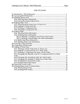
1
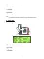
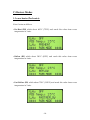
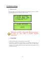
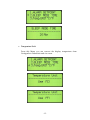
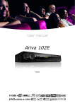
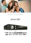
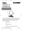
JOVY SYSTEMS RE-7500 User Manual Rev. 1.60 Index - Introduction ……………………………………………........... 3 - Copyrights and Liability disclaimer…..………….....……... 3 - Specifications………………………….………………….…… 4 - Safety/ Caution instructions..…………...………………. 4 - RE-7500 hardware description …….........……….……..…… 6 - Operation …………………………………………….................7 A) Keys Function of RE-7500 …………............…….7 B) Operation modes.………...………...........……...... 7 C) Heaters modes……………………....................…. 10 D) Machine settings……………................................. 12 E) How to start………………………….........….........14 F) R-E7500 Pre-programmed Profiles……................15 G) Control room software........................................... 21 -2- Introduction The IR Technology used gives the RE-7500 the opportunity to fit in a wide range and variety of applications fields, for example, GSM, Networking, Medical, and Military fields as well. This makes RE-7500, the optimum solution to a large sector of the BGA & SMD reworking communities. This manual structure enable a technician with no previous knowledge of the system, to become familiar with the operation and maintenance using RE7500 Reworking System. The safety section of the manual explains the inherent dangers presented by any type of soldering/de-soldering equipment and warnings to minimize the risk of injury due to ignorance. Copyrights and Liability Disclaimer The RE-7500 package, including any hard copies and soft copies, are copyright protected. The purchase of the programs confers the right to make back-up copies of the software included in the package only. To the maximum extent permitted by applicable law, in no event shall manufacturer be liable for any damages whatsoever (including without limitation, special, incidental, consequential, or indirect damages for personal injury, loss of business profits, business interruption, loss of business information, or any other pecuniary loss) arising out of the use of or inability to use this product, even if manufacturer has been advised of the possibility of such damages. In any case, manufacturer’s entire liability under any provision of this agreement shall be limited to the amount actually paid by you for the SOFTWARE and/or HARDWARE. -3- Specifications Top heater Power Max. 300W Pre heater Power Max. 600W Voltage frequency 220 Volts 50 HZ Max board Size 350 mm x 450 mm Gross weight 16 KG Operation Temperature +5~+45 C / +41~+113 F Operation Humidity 20~95% Safety/Caution instructions For Safety reasons, please note the following carefully This unit operates by electricity. And some components within the device have high dangerous voltages applied to them. Failing to follow the operating instructions could result in death, serious injuries, and/or extensive damage to property! Never open the housing or one of the Infrared heaters while main plug is connected. Do not use the units for any purpose other than which they are intended to. Use it according to the operating instructions. This equipment must not be switched on or used without supervision. The unit should switched-off or in idle state while not in use, leaving it ON may cause overheating. -4- Do not place any flammable material on the vicinity of the Infrared heater. Do not allow the spillage of any liquid to on the ceramic emitter as damage may occur. Please use the Infrared heater only on a level and non flammable surface. When the Infrared heater is in use, its housing and the areas exposed to the infrared rays can reach high level of temperature. Please do not touch the housing until it cooled down. Any maintenance of the units is only permitted by a JOVY SYSTEMS certified service technician. Please also pay attention to the safety regulations applied in your area. -5- RE-7500 Hardware Description 1- Upper Heater 2- Down Heater (Pre-Heater) 3- Thermocouple 4- LCD 5- X-Y Table 6- Cooling Fan 7- Laser Pointer 8- Guard Glass 9- Control Switches 10- Power Plug 11- Power Switch 12- Fuses 13- Thermocouple Plug 14- USB Port -615- Picking-Up Tube Operation A) Keys Functions of RE-7500 - Upper Heater (UP-Down keys): used only to change Upper Heater Status. - Lower Heater (UP-Down keys): used to change Lower Heater Status and to scroll up & down in menu also to setup any machine settings. - OK/Menu: used to open menu and also to select any item inside the Menu . - Fan/Cancel: it has two statuses, 1st when you are viewing a menu it will act to cancel and 2nd when you are outside any menu it will power ON the cooling Fan. (if Re-7500 in Parking mode) - Pump: used to Power Pump ON/OFF only. B) Operation Modes: 1 - Park Mode: -7- In this mode the below functions are active: - Lower heater. - Cooling Fan. - Laser pointer. - Suction pump. Note: In Park Mode the upper heater is always OFF (except while applying a profile). 2– Normal Mode: In this mode the below functions are active: - Lower heater. - Upper heater. - Suction pump. -8- Note: In Normal Mode the cooling fan and laser pointer are always OFF. 3- Profile Mode(Pre-Programmed mode): - Profile 1 is a user's pre-programmed profile. (The default application programmed is DCTX for mobile boards application) - Profile 2 is a user's pre-programmed profile. (The default application programmed is North bridge for computer PC motherboard application) - Lead free pre-programmed profile for lead free PCB applications. - To upload/create a profile into RE-7500 please refer to Part (G) Control room software. 4- PC and USB modes: - Connect the USB cable between the machine and the computer. - By operating the Software, the machine will be in USB mode. - By pressing any key on the keypad you will exit this mode. -9- C) Heaters Modes 1- Lower heater (Pre-heater): It has 3 states as follows: - Pre-Heat (PH) which about 400°C (752°F) and reach this value from room temperature in 3 min. - Reflow (RF) which about 500°C (932°F) and reach this value from room temperature in 4 min. - Fast Reflow (FR) which about 750°C (1382°F) and reach this value from room temperature in 5 min. -10- 2- Upper Heater : It has 2 states as follows: - Reflow (RF): which about 600°C (1112°F) and reach this value from room temperature in 50 seconds. - Fast Reflow (FR): which about 800°C (1472°F) and reach this value from room temperature in 1 min. Note: To reach the maximum temperature as in each state above you have to consider the below points: 1- Room temperature is measured as 25°C (77°F) 2- To reach every required temperature you have to start the state from the beginning. -11- D) Machine Settings Alarm Set point: From this Menu you can adjust the alarm of the machine to beep in a certain temperature between 20°C (68°F) to 400°C (752°F). When you scroll UP & Down this Menu do not press the Key for more than 3 seconds (System Protection). Sleep Mode: - In this mode all parts of the machine are turned OFF. This mode is designed to assure safety of the machine and the User as well. In this mode you can adjust a timer between 5 min to 30 min. IF the machine is left working without any key is pressed for this period, it will go into sleep mode. -12- Temperature Unit: From this Menu you can convert the display temperature from Centigrade to Fahrenheit and vise versa. -13- E) How to start - Adjust the PCB to the XY table out of operation area. - Every time you power ON the machine you should leave the Lower Heater on Reflow Mode for 5 min until the Guard Glass become saturated with heat. - You should align the PCB using the Laser pointer so that the pointer will be in the center of the desired component. - Make sure that the machine is situated in Park Mode. - Put the Thermocouple (TC) in any place near to the desired component. - Adjust the lower Heater to the desired mode. - If you have any component which can be affected or damaged by excess heat, you should cover it with reflective tape to prevent Infrared rays to reach it. - Monitor the screen until the PCB reach a temperature from 80°C (176°F) to 120°C (248°F) . - Rotate the upper heater so the machine enters the Normal Mode, and then adjust the upper heater to the desired mode. - Monitor the screen until the PCB reaches a temperature between 180°C (356°F) and 230°C (446°F). -14- - Switch the Pump On to pick up the component (BGA, CSP, etc…) by the suction pen or use any other removal tool like tweezers to remove other type of components (plastic parts, connectors, etc…). - Turn the machine to Park Mode and switch the Fan On (Fan Button) to start the cooling stage. F) RE-7500 pre-programmed Profiles - Using Profiling feature in Jovy Systems Re-7500 you can control the mode of the two heaters during the process at required temperature. - In RE-7500 control panel you can only run the profile which already uploaded to the machine. - To create your own profile and upload it to the machine you must use the Control Room software, also you can run the profile using the same software. - To start run a profile the machine must be in Park Mode. - During run profile you will have no control on the machine so you must take care to run the correct profile otherwise you may use the cancel button to exit the profile Mode. - RE-7500 has 3 readymade profiles Lead free, Profile 1, Profile 2. - The success time for a profile varies according to room temperature and adjusting the upper heater level so we recommend that you use your own profile. -15- Before start profile we advice to set the machine alarm to 300°C (572°F) or higher so that not to interrupt the process. In profile, the upper heater can work in Park Mode so you must take care not to put any heat sensitive material in this area. 1- Retrieve profile 1, 2 or 3 from the machine: - Choose a profile which is compatible with your application from profiles 1, 2 or 3 and press retrieve. - Revise the temperature in end of each phase; also you can change it if required. - Press run profile, the process will automatically start till the process finished. 2- Create your own profile: 1- Introduction: There are three phases included in the profile system provided by RE-7500 control room software. This is to matching all composition of soldering material’s thermal profile requirements to achieve the best result in any process. User could control the heaters modes, machine modes and the desired temperature to end each phase, this implemented in the three phases (preheat, soak and re-flow). The most efficient factor is to start your profile when PCB is completely finished the pre-profile process which guarantee the safety and success for the profile process. -16- Pre- profile process should be in these sequent steps as follow: Use the Thermo couple in bended end method as shown below Machine mode should be in park mode Lower heart mode should be in Reflow Mode (RF) Keep the process running till the PCB temperature read 60°C The pre-profile process at that temperature is end, and user could start the profile process. 2- Creation the profile: In the profile system screen as the guided photo's shows, all the parameters are mandatory fields and user should fill it with the desired values or contents. 1- Temperature set point for X1 , X2 and X3 user should define the temperature which will end that phase , for going toward the next phase or to end that profile (in X3) 2- Message for X1, X2 or X3 is a hint or remark to be shown in a separate window, when the stage has been end. 3- Lower Heater State, to define which power or heater mode user required in each stage. using lower heater in fast reflow mode (FR) in Soaking or Reflowing stages /Phases are very dangerous concerning the PCB safety and process efficiency. 4- Upper Heater Status, to define which power or heater mode user required in each stage. In the upper heater adjustment user should consider the height or level he uses at certain heater mode and stage as well. -17- 5- Machine Mode, user could choose between the Park Mode or Normal Mode depends on whether the upper heater should operate at that stage (Normal Mode) or using the lower heater only (Park Mode). 6- General Parameters: for profile name it shows the current profile name has attempted to Run. File name panel allow the user to save the profile graph in specific name and location, Fan panel is to activate the fan after each stage end. Now the profile is ready to run. -18- 3- Sample Guide Profile This is a sample guide profile for reflow a lead free application and it is highly recommended that every user to revise the settings according to the PCB material, number of components in the PCB and the IC package thermal profile recommended by each manufacturers of the IC package. The figures above include the following settings: Preheat Phase Lower heater in Fast reflow mode Upper heater in Reflow mode Message is “To Soak” Phase (12 characters only to be filled in this panel) Machine mode in Normal Mode Upper heater height in level 4 -19- Soak Phase Reflow Phase Phase End when PCB temperature reaches 100°C Lower heater in Reflow mode Upper heater in Fast reflow mode Message is upper heater height to level 3 (12 characters only to be filled in this panel) Machine mode in Normal Mode Upper heater height in level 4 Phase End when PCB temperature reaches 175°C Lower heater in Preheat mode Upper heater in Reflow mode Message is PEAK…(12 characters only to be filled in this panel) Machine mode in Normal Mode Upper heater height in level 3 Phase End when PCB temperature reaches 205°C Achieve the peak time for ideal melting of Lead Free applications After each profile end, it is recommended not to start the cooling stage. To accomplish ideal peaking time do the following: 1- Set the reflow phase temperature less than the highest temperature required for the application (Example: if the application required 215 – 217 °C set the reflow temperature to 205°C) 2- The temperature will continuously rise after the profile ends from 10 to 15 seconds. 3- When the temperature reading reached to the desired temperature, change the machine mode to “Park mode”. 4- The temperature will starts to fall down 2°C/Sec., when the PCB temperature reaches >100°C you can press the fan button and start the fast cooling phase. -20- G) Control Room software With RE-7500 (Control Room) Software, the Complete Rework process can be archived and documented. The USB Connection between RE-7500 and PC facilitates temperature monitoring/Capture, as well as setting System parameters and Profiles to be as easy as making your Rework tasks completely automated from your PC. To be able to use the RE-7500 (Control Room) Software, you have to insure the installation of the Driver correctly. Be sure not to connect the Machine to your PC until you install the RE-7500 (Control Room) Software first. 1- Installation a. Run RE-7500 (Control Room) Setup (available in the Customer Area at www.jovy-systems.com). b. Follow the on-screen instructions until installation is completed. c. After successfully installing RE-7500 (Control Room) software , you can connect the RE-7500 to your PC USB Port. d. System will detect your Machine automatically and ask for installing the USB Device Driver. e. USB Device Driver can be located under the default folder you specified for installing the (Control Room) software (example: C:\Program Files\JOVY Systems\RE-7500 Control Room\USB Driver\). f. After successfully installing the USB device driver, your machine is ready to be controlled and monitored by (Control Room) software. -21- g. For best results, it’s highly recommended to use the supplied USB device driver, unless otherwise mentioned. Always avoid using longer USB cables than the standard cable bundled with your machine. Longer cables can lower communication reliability between PC and your RE-7500 Rework system. In case you need a new cable, always use trusted brand and quality. 2- Operating Software a. After installing the Setup application, Program will create a Desktop Icon Automatically. b. If the USB Device Driver was installed successfully and your Machine is connected, you can run the RE-7500 Control Room by double clicking the desktop icon. c. If your machine was not automatically detected by (Control Room) software within 15-20 Seconds, Click Tools Connect to RE-7500. Your Control Room software will read the Machine Serial Number and Firmware ID as well. -22-