1
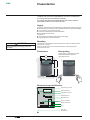
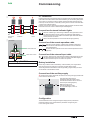
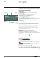
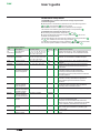
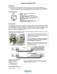
MV electrical network management
DAX
Overcurrent fault detector
for underground lines
Installer and user manual
Presentation
DAX
The DAX is an overcurrent fault detector for use on underground
or underground and overhead MV networks.
It complies with Electricité Réseau Distribution France (ERDF)
specification HN 45-S-50 of October 1981.
Supply
On delivery, check that the received equipment complies with the following supply list:
b The DAX detector, consisting of a box containing the electronic board and a battery
b One or three CTs and a connecting cable
b One or two indicator lights for external installation
b The installer and user manual.
The battery is:
b AA type (small) for a detector with auxiliary power supply
b D type (large) for a stand alone detector.
Mounting
WARNING
The DAX box is mounted without removing the cover, with four countersunk head
screws of dia. 5 x 60 mm
Leave an access zone of 40 mm around the DAX box, to allow opening and
clearance for the cover.
When carrying out any work on a DAX detector
with an auxiliary power supply, disconnect
the power.
Dimensions
Box opening
To open the box, press slightly on either
side of the lower part of the cover.
Then raise the cover.
200
DE55367
DE55370
175
45
215
280
Access zone
DE55368
Electronic board architecture
Programming connector
Display
“Reset” pushbutton
Large battery connector
Small battery (AA)
Large battery (D)
Screw-on terminals
Supply disconnector
Fuse
Spare fuse
(in plastic box)
2
NT00302-EN-01
Commissioning
DAX
DE55369
CT connection
Install the three CTs around the MV cables in compliance with the positioning direction,
green side towards the busbar and red side towards the grid. Connect the green/yellow
wire of each CT secondary winding to the MV switchboard earth terminal and plug
the two-pin connector of the CT secondary winding to the connector at the end of the
“current input” cable termination.
Pass the “current input” cable through a detector cable gland and connect the cable
termination to the four screw-on terminals (see cable diagram).
Connection of external indicator lights
– 1 +
Pass the “indicator light” cable through a detector cable gland and connect
MV
installation
Fault
the cable termination to the two screw-on terminals (see cable diagram).
Connect the other end of the cable to the indicator light. Make sure that the
correct poles are connected.
3 CTs
of DAX
– 2 +
Perform the same operation for the second indicator light (optional).
MV cubicle
Connection of the remote operation cable
Pass the “remote operation” cable through a detector cable gland
and connect the cable termination to the three screw-on terminals
(see cable diagram).
1
MV cable earth braid
Perform the same operation for the second remote operation channel
(optional).
2
Core
Connection of the external input cable
Cubicle earth collector
Pass the “external input” cable through a detector cable gland and connect
the cable termination to the two screw-on terminals (see cable diagram).
The second external input is not used in this product.
1
CAUTION
Battery installation
Pass the MV cable earth braid inside the CT.
When using a detector with a small battery, install the battery in its support while
ensuring that the correct poles are connected. The DAX detector starts.
When using the stand alone detector with a large battery, plug the battery connector
into the board. The DAX detector starts.
Connection of the auxiliary supply
d Check that the supply cable does not enter the box through the grey shaded area
shown below or behind the box.
Pass the supply cable through
the detector cable gland and connect
the cable termination to the two screw-on
terminals (see cabling diagram).
DE55371
DE55365
MV
underground
network
150
150
150
Make the supply circuit.
The internal red light, shown
as a sinusoidal signal, comes on.
Configuration
The DAX detector can be configured using the display and the pushbuttons
(Parameters Setup menu). More details on parameter changes are given
in the “User’s guide” section.
NT00302-EN-01
3
Commissioning
DAX
DE55372EN
Wiring diagram of the DAX detector
Currents
External inputs
1
2
Light 1
– 1 +
Light 2
– 2 +
–
–
S2
S1
Single CT
mounting
1/2200
In I1 I2 I3
Auxiliary
supply
CTs
Remote operation
Light
1
Light
2
S1
S2
+
Three CTs
mounting
1/2200
Remote control 2
Remote control 1
2
Mains
N
1
Neutral
+
Normally
open
Common
L
Phase
Normally
open
Normally
closed
Common
Normally
closed
External input
Changing the fuse
There is a spare fuse in the lower part of the DAX box base.
Its references are as follows: dimensions = 5 x 20, In = 250 mA fast-acting.
Changing the battery
1
The battery must be replaced if defective. In the case of a stand alone detector
with a large battery, the securing collar has to be cut and changed.
1
PE58780p
When replacing the battery, the operating parameters and the meter values
are stored in memory.
Box closure
To close the box, first insert the lugs on the upper part of the cover in the base.
Close the cover down over the base until completely blocked. A lead seal
can be placed on the lower part of the box.
2
2
Spare parts
Sealings
4
Contact our after-sales service.
NT00302-EN-01
User’s guide
DAX
The DAX detector is activated as soon as the lithium battery is connected.
The detector displays the current version of the software followed by the main menu.
Man-Machine Interface (MMI)
The MMI consists of:
3Io Threshold 1
or Imax fault
Display
“Auxiliary
supply” light
b An LCD display presents the menus, parameters, values and messages
on a 16-character display.
b Four pushbuttons:
for setting the detector to standby (rearming),
v one pushbutton
or starting the test mode on prolonged pressing
v two pushbuttons
and
for navigating in the menus
and scrolling through the parameter values
v one pushbutton
for validating a selection or an input value.
Rearm
PE58781
Test
3Io Threshold 2
fault (optional)
Standby/ Navigation Validation
Test
Pushbuttons
“On” light
b Two to four internal indicator lights:
v a green light which comes on periodically to indicate that the detector is operating
v a red light to indicate the presence of an auxiliary supply
v a flashing yellow light to indicate detected faults associated with the thresholds 3Io
Threshold 1 or Imax
v a second flashing yellow light to indicate detected faults associated with threshold 3Io
Threshold 2 (optional).
b One or two external lights
These are connected and supplied by the DAX box and allow signalling of faults
outside the substation (the second is optional); these two lights are linked to
the two internal yellow lights.
In the absence of pushbutton operation, the display switches off automatically
after a certain period of time. It can be started by pressing any pushbutton:
it then displays the current version of the software, and if appropriate the fault
currently indicated followed by the main menu.
Main menu
The DAX detector presents two options in the main menu:
b INFOrmation menu: this displays the detected alarms and fault meters
b PARAMetering menu: this allows the parameters to be consulted and/or changed.
The operator can:
b Select a menu using the pushbuttons
b Validate selection using the pushbutton
and
.
Information menu
The INFO menu allows display of:
b
v
v
v
If applicable, the currently indicated fault:
earth fault associated with 3Io Threshold 1
earth fault sequence associated with 3Io Threshold 2
phase fault associated with Imax threshold.
b Meter (number of validated faults): overcurrent lasting longer than the validation
period
b Period > 40 ms (number of unvalidated faults): overcurrent lasting longer than
40 ms, but shorter than the validation period.
The operator can:
b Consult this information using buttons
and
b Reset the meters by prolonged pressing on the pushbutton
when displaying a
meter. Confirmation is requested. To do this, pushbuttons
and
allow the Yes
option to be selected, then the operator validates confirmation using the pushbutton
.
NT00302-EN-01
5
User’s guide
DAX
Parameters Setup menu
The PARAM menu is used to consult and/or change the parameters
in the following table:
b READ submenu: this allows the parameters to be consulted using buttons
and
. The pushbutton
serves no purpose
b MODIFication submenu: this allows the parameters to be changed.
This submenu is accessed by prolonged pressing on the pushbutton
.
In the Modification submenu the operator can:
b Scroll through the parameters using buttons
and
b Change the displayed parameters using the pushbutton
; the current
parameter value starts to flash.
The operator selects a new value from the possible values using pushbuttons
, then validates the new value using pushbutton
.
and
A confirmation is requested: to do this, pushbuttons
and
are used to select
.
Yes, then the operator validates confirmation using the pushbutton
Operating parameters
Title
Description
3lo
Zero sequence
Threshold 1 threshold 1
3lo
Zero sequence
Threshold 2 threshold 2
Possible values
5 - 10 - 15 - 20 - 25 - 30 - 40
50 - 60 - 70 - 80 - 100 - 120
140 - 160 - 180 - ggg
5 - 10 - 15 - 20 - 25 - 30 - 40
50 - 60 - 70 - 80 - 100 - 120
140 - 160 - 180 - ggg
225 - 450 - 630 - 700 - ggg
Factory
80
Unit
A
Additional information
Special value shown by “ggg” disables earth fault
detection. 3Io threshold 1 is the standard threshold.
ggg
A
Special value shown by “ggg” disables earth fault
detection. 3lo Threshold 2 is available as option.
450
A
Special value shown by “ggg” disables phase fault
detection.
Duration above which the overcurrent is declared
as being a fault, applicable to the earth faults and
phase faults.
Waiting time between activation of the indicator light
and remote operation contact changeover.
This delay is intended to filter transient faults
(eliminated by the reset cycles) before their indication
to remote operation.
Duration above which the detector automatically
switches to standby status after the appearance
of the indicator light and in the absence of other
conditions.
The external input 1 of the detector is intended to receive
an external contact in order to return the detector
to standby status. Available as option.
Available on the detector with auxiliary power supply.
Imax
Phase threshold
Validation
Fault validation period 60 - 100 - 200 - 300 - 360
300
ms
RL delay
Delay associated
with remote operation
contact changeover
0 - 50 - 90 - 140
0
s
Rearm Auto Signalling duration
1 - 2 - 4 - 8 - 16 - 24 - 36 - 96
2
h
Rearm Ext
Activated / Inhibited
Inhibited
Activated / Inhibited
Activated
Activated / Inhibited
Inhibited
Activated / Inhibited
Inhibited
Rearm Ubt
Rearm I
Inrush
Return to standby
status by external
input changeover
Return to standby
status by the presence
of auxiliary voltage
Return to standby
status by presence
of current on MV grid
Filtering of inrush
current
Light 1
Type of external lights
installed
Fixed / Pulsating
Fixed
Contrast
Adjustment of the
display contrast
–1 - 0 - +1
0
6
The detector is able to filter the inrush currents so that
they are not considered as faults.
This option cannot be activated if the “Rearm Ext”,
“Rearm Ubt” and “Rearm I” parameters are all inhibited
or if the “Validation” parameter is less than 200 ms.
The detector can be connected to two types of indicator
lights: “fixed” type as standard or “pulsating” type
in some cases.
The display contrast can be adapted to the conditions
of use.
NT00302-EN-01
User’s guide
DAX
Tests
Rearm
Test
After prolonged pressing on the “Rearm/Test” pushbutton, the DAX detector starts
a test. This test involves activating the remote operation dry contacts and the internal
and external indicator lights.
Activation of the dry contacts and the indicator lights stops as soon as
the “Rearm/Test” pushbutton is pressed or after one minute.
Rearming modes
When the detector is in the fault signalling phase, it is rearmed (returned to standby
mode) by the first activated condition from the following:
b Pressing on the “Rearm/Test” pushbutton
b The end of the signalling period (Rearm Auto)
b Switching of external contact input 1 (Rearm Ext), for the version equipped
with this contact
b Presence of auxiliary voltage (Rearm Ubt), for the LV + battery version
b Current present in the CTs (Rearm I).
Maintenance
Small battery life: more than 8 years and 700 hours’ signalling.
Replacement of the large battery: every 5 years (with 250 hours’ signalling).
NT00302-EN-01
7
Schneider Electric Telecontrol
839 Chemin des Batterses - Z.I. Ouest
01700 St Maurice de Beynost
Tél.: +33 (0)4 78 55 13 13
Fax: +33 (0)4 78 55 50 00
http://www.schneider-electric.com
E-mail: [email protected]
NT00302-EN-01
As standards, specifications and designs change from time
to time, please ask for confirmation of the information given
in this publication.
Publishing: Schneider Electric Industries SAS
Production: Graphème
Printing: Made in France
This document has been
printed on recycled paper
01-2012
© Schneider Electric Industries SAS - All rights reserved
Schneider Electric Industries SAS