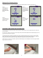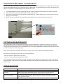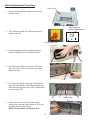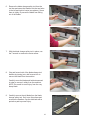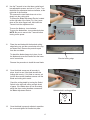
1
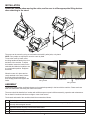
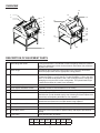
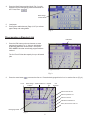
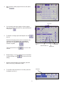
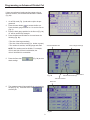
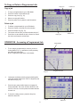
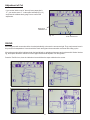
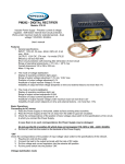
Cut-True 27A
Automatic Programmable Electric Paper Cutter
9/2014
OPERATOR MANUAL
FIRST EDITION
TABLE OF CONTENTS
TOPIC
PAGE
Specifications
Safety Guidelines
Installation / Assembly
Overview
Description of Equipment Parts
Operation - Basic Cut
Programming a Standard Job
Programming a Divided Cut
Programming an Advanced Divided Cut
Copy or Delete a Programmed Job
Accessing a Programmed Job
Adjustment of Cut
Maintenance - Oiling
Adjusting the Back Gauge Advance Distance
Signals
Version of Cutter
Display of the Clamping System
Replacing the Cutting Stick
Troubleshooting
Adjusting Blade Height/Cutting Depth
Cutting Blade Maintenance
Replacing the Cutting Blade
1
1
2
3
3-4
4-5
5-6
7
8
9
10
10
10
11
11
11
12
12
13
13
13
14 - 17
Cut-True 27A Guillotine Cutter
SPECIFICATIONS
Cutting Action:
Maximum Cutting Width:
Maximum Paper Stack Height:
LED / Laser Cut Line:
Clamp Style:
Back Gauge Adjustment:
Back Gauge Reading:
Programmable Jobs:
Blade Change Safety Tool:
Dimensions:
Weight:
Power Supply:
Safety Certifications:
Metal Stand with Shelf:
Dual-button electric
18.9” (480mm)
3.15” (80mm)
Yes
Automatic
Touchscreen or electronic hand wheel
Digital readout, in both inches and metric
Up to 99, with up to 30 cuts
Included
60” H x 36” W x 40” D (1520mm H x 920mm W x 1000mm D)
575 lbs. (260kg)
110V, 20A dedicated line
CE approved, UL pending
Included, some assembly required
SAFETY GUIDELINES
*
Operators should read this manual prior to using the cutter.
*
The Cut-True 27A should only be used by one person at a time.
*
Keep hands away from the cutting area. The cutter is operated by pressing two “enable switches” simultaneously.
*
Do not disassemble Plexiglas safety covers, and never attempt to change the settings of any protective devices.
*
Do not grasp underneath the blade edge.
*
When changing the blade, carefully follow the instructions in this manual, and be sure to use the supplied Blade
Change Safety Tool. Wear leather gloves to provide additional safety.
*
The Cut-True 27A is designed to cut only paper. DO NOT attempt to cut non-paper materials including metal sheets,
wood, plastic or anything other than paper. Machine damage and/or personal injury may occur.
*
Be sure to check the safety devices before each operating session.
1
INSTALLATION
Please use caution when moving the cutter, and be sure to utilize appropriate lifting devices
when attaching to the stand.
The cutter can be moved by using an overhead motorized lift, pallet jacks, or by hand.
NOTE: Four people are required to move the cutter by hand.
To move the cutter by hand, utilize
the lifting handles located on the front
and back of the machine. To adjust
the handles, loosen the knobs on the
underside and slide the handles to out
to a comfortable position. Retighten
the knobs.
Lifting handle
1500mm
When the cutter is in place and securely attached to the stand, loosen
the knobs, adjust the handles to
their storage position and tighten the
knobs.
Adjustment knob
Adjustment knob
Lifting handles
1000mm
ASSEMBLY
1000mm
The wooden paper pusher and blade change tool are packed
separately in the box with the machine. Please set these
1000mm
1000mm
aside and install after connecting the cutter to the stand.
The cutter should be installed in a location with sufficient space to permit efficient assembly, operation and maintenance.
Do not install in locations with direct sunlight or near a heat source.
The chassis and stand of the machine should be connected as follows:
1.
Set the legs so the 4 threaded pins point upward.
2.
Assemble the crossbars of the stand so the color labels on each match the corresponding legs. Fasten stand
securely with hexagonal screws.
3.
Place the chassis correctly onto the assembled stand.
4.
Tighten the four hexagonal nuts.
5.
Position stand shelf in place and fasten securely with enclosed screws.
03
2
OVERVIEW
14
1
13
4
2
3
15
11
5
6
7
8
9
16
18
19
20
21
12
16
17
22
10
DESCRIPTION OF EQUIPMENT PARTS
1.
Side Gauge with Scale
In mm/cm and inches. The indicator on the back-gauge shows the measurement. Fine adjustment is done via the electronic hand wheel (20). Minimum
adjustment is 0.5mm.
2.
Back Gauge
Operated by the touchscreen control panel or the electronic hand wheel.
Moves the paper stack into the appropriate cutting position.
3.
Blade Adjustment Access
The blade height can be adjusted up to 2mm by using the adjustment screw.
To lower the blade (+), turn to the left. To raise the blade (-), turn to the right.
NOTE: If the blade is adjusted too low, it will cut deeply into the cutting stick,
damaging not only the stick but the cutting blade. The optimal blade height
is when the last sheet in a stack is cut accurately.
4.
Carrier (support)
Carries the blade holder and the entire mechanism of the machine.
5.
Three Socket Headless Screws
Adjustable screws to level the blade for even cutting.
6.
Cutting Blade
Made of high-quality carbon steel.
7.
Blade Holder
Holds blade in place. There are five screws for blade positioning, (which
should be set up and released step-by-step following the blade replacement
instructions) and adjusting the blade for even operation.
8.
Cutting Stick
Plastic stick which protects the edge of the blade during cutting. Can be
repositioned and used on all four sides before being replaced.
9.
Cutting Stick Access Slot
Insert screwdriver here in order to lift and remove cutting stick.
10.
Stand
Steel stand with shelf, assembly required.
11.
Rear Safety Cover
Clear plexi cover is provided for operator safety and helps to prevent dust
buildup.
12.
Fuse Panel
There are six fuses, as follows:
FU1
FU2
FU3
FU4
10A
10A
10A
10A
FU5
3
FU6
FU7
FU8
2A
2A
13.
Infrared Light Beam Safety Curtain
The infrared light beam safety curtain will be activated automatically once
the cutter is powered on. Green LED indicators show when it is activated.
Red LED indicators show when the beam has been broken.
14.
Touchscreen Control Panel
Use the LCD touchscreen to program up to 99 jobs, up to 30 cuts each.
15.
Cover
Attached to the cutter with eight screws. Disassemble only in case of blade
change or maintenance.
16.
Clamp Enable Switches
Press and hold the two clamp enable switches to clamp the paper securely
in place. The clamp switches are indicated by this icon
The right switch is
used for both clamp and blade activation.
17.
Cutting Blade Enable Switch
Press and hold the two blade enable switches to activate the blade and cut
paper. The blade switches are indicated by this icon
The right switch is
used for both clamp and blade activation, in conjunction with this green
button.
18.
Key-Activated Mode Select Switch
Turn to right for cutting. Turn to left for blade replacement. Turn to middle to
stop all operations.
19.
Power Light
Shows when machine is powered on.
20.
Electronic Hand Wheel
Used to adjust back gauge to appropriate paper size and cut length.
To move the back gauge toward the operator, turn clockwise.
To move the back gauge away from the operator, turn counterclockwise.
21.
Power Switch
Used to turn on and off power to the cutter.
22.
Paper Alignment Bar
Steel side bar helps to align the paper prior to cutting.
LED Laser Cutting Line (not shown) Shows operator exactly where the blade will cut the paper stack.
Wooden Push Block (not shown)
Used to help align paper stacks for precise cutting.
Blade Change Safety Tool
(not shown)
This device is used to safely remove the blade when it needs to be
sharpened or replaced.
Tool Kit (not shown)
Includes T-wrench and interchangeable bits for use in adjustments and
blade replacement.
OPERATION - Basic Cut
Cutting Mode
1.
Plug in the cutter to an appropriate power outlet
(110V 20 Amp dedicated). Turn on red power switch.
2.
Choose metric or inch measurements by pressing
either the “cm” or “inch” box on the touchscreen
(Fig. 1). Then touch the back gage block, and a keypad will appear (Fig. 2)
3.
Be sure the key-activated mode select switch (page 4,
part #18) is turned to the right on Cut mode “I” .
Fig. 1
4
Edit Mode
Clamping Bar Display
Back gauge block
Tools
4.
Press the Back Gauge position block (Fig. 2) on the
keypad to set the back gauge position for desired cut
size. Press Enter.
Back Gauge
Position Block
5.
Load paper.
6.
Press green enable buttons (Page 4, #17) to activate
paper clamp and cutting blade.
Fig. 2
Programming a Standard Job
Edit Mode
1.
Press the Edit button on the touchscreen to enter
programming mode (Fig. 3). Select a Job Number
by pressing that block on the screen. Then press
Enter. NOTE: Jobs that are already programmed are
outlined.
The Cut-True 27A has the capacity for up to 99 saved
jobs.
Programmed Jobs
Enter
Fig. 3
2.
Press the enter button
Cut #
to access the first cut. Press the back gauge block of cut 1 to set the first cut (Fig. 4).
Back Gauge Advance After Cut
Position
Repeat
Cut
# of
Repeats
Move to the first cut
Move to previous cut
Move to next cut
Delete the selected cut
Enter, and move to next cut
Back gauge block
Fig. 4
5
3.
Enter position of back gauge for first cut, then press
Enter.
Fig. 5
Save icon
4.
If you would like the back gauge to slide the paper
stack forward after making the cut, press the Advance
icon (Fig. 6).
5.
To repeat a cut length, press the Repeat Cut icon
(Fig. 6).
Press the back gauge block of the cut number to be
repeated enter the length of the cut and then
press the # of Repeats icon
to key in the
number of repeats.
Then press the Enter icon
next cut.
Fig. 6
to move to the
6.
Repeat steps 2 - 5 for any additional cuts. Remember
to press the Enter icon
to move to the next
setting.
7.
When all cuts and settings are complete, press the
Save icon (Fig. 6), and choose “Save.”
8.
To exit Edit mode and return to Cut mode, press the
Cut Mode icon (Fig. 7).
Cut Mode
Fig. 7
6
Advance After Cut
# of Repeats
Repeat Cut
Programming a Divided Cut
If all cuts on a sheet are the same length (i.e. no border or
full bleed and no gutter between cuts), simply program a
Divided Cut (Fig. 8).
1. Go to the Edit mode (Fig. 3) and select a job to be
programmed.
2. Press the enter button
to access the first cut.
Press the back gauge block of cut 1 to set the first cut
(Fig. 4).
3. Enter the back gauge position for the first cut (Fig. 8a).
15” will be used for this example.
Fig. 8a
4. Press the Divided Cut icon and enter the total paper
length, and the # of sections and press the Save
button
(Fig. 8b).
Divided Cut
Total Paper Length
NOTE: The number must be divisible. For example,
15/5=3 and 10/4=2.50 are both divisible, but
14/6=2.333333333 is not divisible.
Fig. 8b
Save Icon
5. The measurements will be automatically calculated for
the job (Fig. 8c). Press the Save icon
to
store the job.
Fig. 8c
7
# of sections
Save Button
Programming an Advanced Divided Cut
If there are top/bottom borders and/or gutters to be cut
between sections, use the Advanced Divided Cut Mode
(Fig. 9b).
1.
Go to Edit mode (Fig. 3) and select a job to be programmed.
2.
Press the enter button
to access the first cut.
Press the back gauge block of cut 1 to set the first cut
(Fig. 4).
3.
Enter the back gauge position for the first cut (Fig. 8a).
15” will be used for this example.
4.
Press the Advanced Divided Cut icon and enter the
following (Fig. 9b):
Fig. 9a
* The size of the large section(s)
* The size of the small section(s) (i.e. border or gutter)
* The number of sections, including large and small
Advanced Divided Cut
Size of large section(s)
NOTE: The number must be divisible. For example,
15/5=3 and 10/4=2.50 are both divisible, but
14/6=2.333333333 is not divisible.
5.
Press the Save icon
these settings.
(Fig. 9b) to store
Save Button
Size of small section(s)
Fig. 9b
Total # of sections
Save Icon
6.
The measurements will automatically be calculated for
the job (Fig. 9c). Press the Save icon
to
store the job.
Fig. 9c
8
To Copy or Delete a Programmed Job
Copy icon
Paste icon
Copy a job
1.
To copy a programmed job, go to Edit Mode.
2.
Press the number of the selected job.
3.
Press the copy icon (Fig. 10).
4.
Select an empty job location.
5.
Press the paste icon to paste the job information.
Delete a job
1.
To delete a programmed job, go to Edit Mode.
2.
Press the number of the job you wish to delete.
3.
Press the Delete icon (Fig. 10).
4.
The screen will read “Do you want to delete this job?”
5.
Press Save to save delete the job or Cancel to cancel
the action and keep the selected job.
Fig. 10
Empty job
OPERATION - Accessing a Programmed Job
1.
Cutting Mode
To cut using a programmed job, be sure you are in
Cutting Mode (Fig. 11), and select a job by pressing
the Job # and press Enter.
NOTE: Programmed jobs have a dark border.
Fig. 11
2.
Load paper, and align to back gauge and side guide
using the wooden push block. Once it’s aligned, press
the Start icon (Fig. 12).
3.
Press the two green enable buttons to engage the
clamp and blade. The cutter will then advance to the
next cut in the list. You must press the enable buttons
for each cut.
4.
To stop the cutting process, press the Stop icon,
below the Start icon.
Fig. 12
9
Programmed Jobs
Start icon
Delete icon
Adjustment of Cut
If you set the initial cut at 18” but only insert paper that is
17”, you need to enter 17” in this space indicated (Fig. 13)
and press the calibrate back gauge icon to confirm the
adjustment.
Back gauge
calibration icon
Fig. 13
Enter number here
OILING
All moving parts with screws should be checked periodically to be sure the screws are tight. They may become loose in
the process of transportation. Users should also check and tighten the screws after more than 200 cutting cycles.
All moving parts should be lubricated and oiled periodically to maintain performance and equipment life. Before lubricating, these parts should be cleaned to remove paper dust and old deposits of oil and grease.
Press the Tool Box icon, then the lubrication icon and follow the steps outlined on the screen.
10
Adjusting the Back Gauge Advance Distance
Back Gauge Advance
Tool Box
To program the distance the back gauge slides the paper
stack forward after making a cut, press the Tool Box icon,
then the Back Gauge Advance icon.
Enter the desired distance in the window, and choose
between inches or cm.
Enter number here
Signals
Signals
Tool Box
To check which systems are currently functioning, press
the Tool Box icon, then the Signals icon.
When the machine is in Idle status, the following signals
will be * ON:
SQ1
SQ2
S1R
SQ6
SF1
SF2
When the infrared laser safety guard is active, the following
signals will be on or off:
S1R
SQ1
SQ6
SQ2
(*ON)
SF1 SF2
(OFF)
Machine Information
Version of Cutter
To check the version of the machine, press the Tool Box
icon, then the Machine Information icon.
11
Tool Box
Display of the Clamping System
This function allows you to see the movements of the paper clamping system. Press the Clamp Status icon.
Stage 1:
The clamping bar
lowers when you
press both of the
green clamp enable
buttons.
Stage 3:
The clamping bar
is going up when
you push either of
the clamp enable
buttons.
Stage 2:
The clamping bar is
holding the stack of
paper securely.
Stage 4:
The clamping bar
is in its original
position.
ROTATING / REPLACING THE CUTTING STICK
The cutting stick is the surface the blade contacts during the cutting process. It can be rotated and used on each side,
4 times altogether.
If the last piece of paper in the stack is not cut through cleanly, and the blade depth has been adjusted properly, the cutting stick should be rotated or replaced.
The cutting stick sits in a channel in the base of the cutter, just below the blade carrier. To remove it, first turn off the
power. Then insert the 5mm screwdriver into the cutting stick access slot (see photo below left) and lift up. Grasp the
cutting stick and remove (see photo below right). Rotate the cutting stick to a new side and re-install.
NOTE: When the cutting stick is rotated or replaced, the blade height must be readjusted. See the next page for blade
height adjustment instructions.
12
ADJUSTING BLADE HEIGHT / CUTTING DEPTH
When the cutting stick is rotated or replaced, or the blade is replaced, the blade height must be readjusted. A blade which
cuts too deeply damages not only the cutting stick but the blade itself. The optimal blade height is when the last sheet in a
stack is cut accurately. The blade height can be adjusted up to 2mm.
1.
The blade adjustment access is on the right side of the cutter, just behind the fuse panel (see picture, below left).
2.
Slide the finger knob down and hold in place to open the access door.
3.
Insert the the T-wrench from the tool kit into the adjustment slot. To lower the blade (+), turn to the left. To raise the
blade (-), turn to the right.
4.
NOTE: You must remove the T-wrench before restoring power to avoid injury or damage to the cutter.
Front of Cutter
Fig. 14b
Fig. 14a
CUTTING BLADE MAINTENANCE
The cutting blade is made of heat-treated high-carbon steel and is designed for repeated use. However, over time the
blade will become dull, and not perform to the highest standards. Cutting heavy paper or cardboard will dull the blade
more quickly than thinner paper stock. A dull blade will not cut accurately. Blade lifetime with normal paper is approximately 1,600 cuts (tested in maximum capacity).
NOTE: If the blade jams in the paper stack or leaves a groove in the paper, it should be changed immediately.
If the blade is not making clean, accurate cuts, check the following:
* Have you rotated or replaced the cutting stick?
* Have you correctly adjusted the height of the blade?
If so, the blade will need to be replaced. The blade can either be re-sharpened by a professional, or it can be replaced
with a new blade. To avoid injury, follow the Blade Changing Procedure and use the Blade Change Safety Tool, included
with the cutter.
TROUBLESHOOTING
Blade doesn’t move
Check if the main motor magnetic contact is activated.
No power
Check power source and all control circuit fuses.
Overload
Wait until the breaker automatically resets, which takes around 30-60 seconds.
The indicator light will be off. Reduce size of paper stack or change blade.
Cutter won’t operate
Press the two “enable switches” again, and be sure nothing is blocking the infrared
safety light beam curtain.
Other issues
Please contact your Formax dealer for service.
13
Resetting the Blade Change Notification Message
When the Cut-True 27A has reached 1,500 cuts, a message will appear on the control panel “CUT1500.” When this
happens, check the blade to see if it is dull or still sharp enough to cut through one sheet of copy paper. If it is dull, replace
the blade using the procedure on the following pages.
If the blade is still sharp, reset the control panel message using these steps:
Step 1: Press
“HOME” to move the
backgauge to the
start position before
resetting the counter.
Step 4:
Press the number on
the screen until the it
reads “Do you want to
delete it?”
This message will
appear on the screen.
Step 5:
Select “SAVE” to
reset the counter to
zero
Step 2:
Select the blade
change icon, shown
here.
Counter is reset to
zero.
Step 3:
The number on the
screen will show
1500.
14
Blade Replacement Procedure
1.
2.
Front Cover
Loosen and remove (8) screws from the cover.
Remove cover.
Select switch in
blade change position
Turn the power switch ON, and turn the select
switch to the left.
Power switch ON
3.
Press two enable switches simultaneously to
move the blade down to the bottom position.
4.
Turn the select switch to the center (OFF) position. Using the T-wrench, remove the far right
blade screw (A).
A
5.
Turn the select switch to the right. The blade will
move up automatically. Once fully retracted, turn
the select switch to the center (OFF) position and
turn the power OFF.
B
6.
Remove the far left screw (B). Remove the
screws to the left and right of center (C & D), but
leave the center screw in place.
NOTE: Do not remove the center screw.
15
C
Center screw
D
6.
Remove the blade change safety tool from the
tool box and screw the handles into the two holes
to the left and right of center (see photos). Screw
them in tightly, to prevent the blade from falling
out of the holder.
7.
With the blade change safety tool in place, use
the T-wrench to remove the center screw.
8.
Grip and loosen both of the blade change tool
handles by turning just a half reverse turn to
remove the blade from the machine.
Carefully move the blade and holder downward
in order to remove it safely from the machine.
NOTE: Be careful to avoid injury from the very
sharp blade.
9.
Carefully remove the old blade from the blade
change safety tool. Set it on a flat surface and
unscrew the handles. Cap the old blade with a
protective pad to prevent injury.
16
10.
Use the T-wrench to turn the three socket headless adjustable screws, and set to “0” point. Turn
the blade fine adjustment device clockwise, at the
right side of the machine.
This ensures the new blade does not cut too
deeply into the cutting stick.
To access the Blade Adjustment Device, located
on the right side of the cutter (Fig. 14a), press
down on the silver finger knob, and insert the
T-wrench into the adjustment slot.
0
-
To move the blade up, turn clockwise.
To move the blade down, turn counterclockwise.
NOTE: Be sure to remove the T-wrench before
turning on the power.
11.
Place the new blade with the beveled cutting
edge facing up, and the screw holes at the top,
as shown here. Remove the protective pad
from the new blade.
To attach the blade change tool, place it over
the blade and screw the handles into the lower
set of screw holes.
Beveled cutting edge
Reverse the procedure to install the new blade.
12.
Once the blade screws are all securely in
place, check to see if the blade touches the
cutting stick evenly. If it is tilted or uneven, adjust the three socket headless screws until the
blade and cutting stick match.
Check the cutting depth by turning the Select
Switch to the right and cutting a single sheet
of paper. If the blade does not cut accurately,
adjust the three socket headless screws and
the Blade Adjustment Device.
13.
Select switch in cutting position
Once the blade is properly adjusted, reposition
the cover and tighten all screws into place.
17
+