1
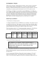
EPROM EMULATOR
USER'S MANUAL
MODEL EE1M
Version 1.1
9-4-92
Copyright (c) Technical Solutions 1991,92
INTRODUCTION:
Thank you for selecting a Technical Solutions product. We have made every attempt to
provide a quality product at an affordable price. Our goal is to provide tools for the
Engineer, Technician and Hobbyist that are inexpensive, but fully functional. If you have
any problems or comments, please don't hesitate to call or FAX us and let us know.
The EE1M uses 128 KBytes of static RAM to emulate EPROMS up to 128 KBytes in
size. An IBM compatible computer (PC) is used to down-load object code into the RAM.
The RAM is dual-ported, allowing both the PC interface circuitry and the target to have
access to it. When the PC starts to download object code, arbitration circuitry disables
the target port and enables the PC interface port. While the download is occurring, the
RESET pins are activated, holding the target in reset until its port is re-enabled.
INSTALLATION:
1. Turn off power to the target system.
2. Configure the EE1M for the size of EPROM you are emulating. Four jumpers are used
to configure the EE1M size. These jumpers are used to isolate/connect the upper address
lines from/to the internal SRAM. Isolating unused upper address lines while emulating a
smaller EPROM makes the EE1M more immune to target socket variances.
The lowest jumper connects A13. The upper most jumper connects A16. The following
table summarizes the proper settings for each EPROM size the EE1M emulates:
A16 (TOP)
A15
A14
A13 (BOT)
2764
OPEN
OPEN
OPEN
OPEN
27128
OPEN
OPEN
OPEN
SHORTED
27256
OPEN
OPEN
SHORTED
SHORTED
27512
OPEN
SHORTED
SHORTED
SHORTED
27010
SHORTED
SHORTED
SHORTED
SHORTED
3. Inset the EE1M into the target socket.
BE CAREFUL TO INSERT THE EE1M PROPERLY.
INSERTING THE EE1M BACKWARDS CAN RESULT IN
PERMANENT DAMAGE TO THE EE1M OR THE
TARGET SYSTEM!
Pin 1 of the EE1M is identified by the small notch in the DIP plug, similar to an IC.
Insert the EPROM Emulator so that this notch points the same direction as the notch on
the target socket.
If you are inserting the EE1M into a 28 pin socket, insert it so that pins 1,2,31 and 32
hang over the end of the socket. This will place pin 3 of the EE1M into pin 1 of the
socket. You will also need to apply power to pin 32 by connecting a jumper to pin 32 or
tack-soldering a wire between pin 30 and pin 32. The remaining pins are designed to
float un-terminated.
4. Select an un-used printer port on your IBM compatible PC/XT/AT.
5. Plug the supplied DB-25 to RJ-11/12 converter into the selected port.
6. Plug one end of the supplied RJ-11/12 cable into the adaptor.
7. Plug the other end of the RJ-11/12 cable into the EE1M jack labeled "IN".
8. For target systems with wider data paths or multiple banks of EPROMS, multiple
EE1Ms can be daisy-chained. Up to four units can be connected for data paths up to 32
bits wide or for up to 4 banks of 8 bit EPROMs. The "OUT" jack of the first EE1M is
connected to the "IN" jack of the next EE1M. This is repeated up to three times. The
Most-Significant-Byte of the Most-Significant bank is loaded into the first EE1M
connected to the PC. The Least-Significant-Byte of the Least-Significant bank is loaded
into the last EE1M in the chain. Therefor, the first byte in the object file will end up in
the last EE1M in the chain. If four EE1Ms are daisy-chained in a 32 bit system, the
second byte will be placed in the next-to-the-last EE1M. The fourth byte will be placed
in the first EE1M in the chain (the one connected directly to the PC).
9. (OPTIONAL) Connect a jumper between one of the reset pins on one of the EE1Ms to
the appropriate place on the target if automatic reset is desired after each download.
RESET and /RESET are TTL/CMOS compatible outputs, capable of sourcing 15
milliamps and sinking 15 milliamps.
10. IF YOUR TARGET HAS IN-CIRCUIT EPROM
PROGRAMMING CAPABILITY, DISABLE IT!
The EE1M is a 5 Volt ONLY device. Programming voltages will DAMAGE the device
and will void the warranty. Even short surges during power-up or reset can be damaging.
11. Apply power to the target system.
12. Run the loader program. We wrote the loader as a command line driven routine
rather than an interactive one. This allows you to run the program from a batch file
without intervention. It can be added directly to your Compile-Link-Locate batch file.
Enter "LD1M" or "BLD1M" without parameters to see the parameter syntax.
Most of the parameters should be self-explanatory, but a few clarifications are in order.
/O:xxxxx Absolute starting address of the EPROM(s) in HEX. EXAMPLE: If you
are placing a 27C512 at the top of memory in an 8086 ( 1M - 64K = F0000), you
would enter " /O:F0000". This parameter is used for Intel Hex or Motorola 'S'
files. It has no effect for binary files. Binary files are assumed to be absolute
binary images of the EPROM. Therefor, the address of the EPROM is irrelevant.
/W:x
Data width (in bits). Valid width = 8,16,24 or 32 bits.
/B:x
Bank count. Valid bank count = 1,2,3 or 4.
**** NOTE: The total number of emulators can not exceed four. Therefor, only the
following combinations of Bank count and Data width are legal:
1.
2.
3.
4.
1,2,3 or 4 banks of 8 bits
1 or 2 banks of 16 bits
1 bank of 24 bits
1 bank of 32 bits
All parameters are optional and can be listed in any order. The Printer Port is specified
by base address rather than LPTx. This allows the use of multi-port parallel cards that do
not map directly into LPT1-LPT3. Most BIOS/DOS compatible printer ports are located
at one of the following I/O addresses: 378, 3BC, or 278.
ADDITIONAL NOTES
1. Most linker/locators will generate Binary files quicker than Intel Hex or Motorola 'S'
files. In addition, the EPROM Emulator downloads Binary files quicker than the other
two because the data does not require conversions. Therefor, for the quickest download
times, we recommend the use of Binary files. It will speed up the linker/locator and the
download process.
With that in mind, we created a new program: BLD1M.EXE. This program works with
BINARY files only. Removing the Intel Hex and Motorola 'S' file conversion routines
from the downloader eliminates the conversion time, the time for buffering an image of
the data in RAM and the overhead of HUGE pointers. This results in a considerable
decrease in download times. BLD1M.EXE does NOT support multiple banks of
EPROMs. It DOES support daisy-chaining for wider data paths. If you are emulating
more than one bank, you must use the original loader; LD1M.EXE.
2. The Eprom Emulator uses high quality machined pin headers for the target socket pins.
However, they are not very forgiving to being bent. We recommend the use of a
"sacrificial" socket between the Eprom Emulator and the target socket. This socket
protects the Eprom Emulator from mechanical damage. If one of the socket pins
becomes bent or damaged, the socket can be replaced a lot easier than the Eprom
Emulator can be repaired. This is common practice for most test equipment that plugs
into target sockets.
3. The RESET and /RESET outputs are driven by TRI-STATED devices. They are
active during the download only.
4. The loader programs have no feedback from the Eprom Emulator. They can not tell if
the Eprom Emulator is plugged in or if power is applied to the target (and therefor the
Emulator).
TROUBLESHOOTING TIPS
1. Verify that the EE1M is communicating with the host. The LED should turn off
during the download, and back on after the download. If the LED stays on or off:
1. Verify that the proper printer port address was specified
2. Verify that the cable is connected properly
3. Verify that the target is powered-up during the down-load
4. Try a different printer port
5. Verify that the EPROM Emulator is plugged in properly
2. Try using a BINARY file if possible. Binary files are simpler and leave less room for
mistakes in locating or specifying offsets.
3. Verify that the EE1M is jumpered properly for the size EPROM being emulated.
4. The Emulator (and therefor the target) must be powered before the object code can be
down-loaded into the Emulator. While the download is occurring, RESET and
/RESET are active to reset the target. After completing the down-load, the reset lines
are returned to their in-active states. If the target attempts to access the Emulator
during down-loading (the reset lines were not connected) it will read whatever data is
being down-loaded at that instant. Once object code is downloaded, it will stay valid
until power is removed or new code is downloaded.
5. Remove any extension cables you may have added to the download cable or the target
socket. We designed the EE1M for as much noise immunity as possible, but the
longer the download cable, the higher the probability you will exceed the noise
margins. We have many customers successfully using 25' or more of cable, but we
cannot guarantee their proper operation.
6. If you do buy a longer modular cable, be sure to purchase one that is wired the same as
the one provided (6 conductor, pin1 to pin1). Note that modular cables can be
purchased in straight through or cross-over configurations.
7. If you have inserted the EE1M into a 28 pin socket, verify:
1. It is inserted so that the ground pin on the EE1M (pin 16) is aligned with the
ground pin (pin 14) of the socket; leaving pins 1,2,31 and 32 hanging over the
edge of the socket. You may need to use a 28 pin socket between the EE1M and
the target socket as a spacer to insure that these pins do NOT short against
anything.
2. +5 volts is applied to pin 32 of the EE1M. This can be accomplished by
soldering a short wire between pins 30 and 32, or by connecting a jumper wire
between pin 32 and +5 Volts on the target board.
If you need additional technical assistance, we can be reached at:
TechTools (formerly Technical Solutions)
P.O. BOX 462101
Garland TX. 75046-2101
Voice or FAX: (972) 272-9392