1
UniROM
User’s Manual
v2.2 7/1/97
TechTools
Copyright (c) 1996,97
Introduction ----------------------------------------------------------- 1
UniROM, a Brief Overview -------------------------------------------------1
Using this manual -------------------------------------------------------------4
Problems, Comments and Suggestions -------------------------------------4
How to Contact Us -----------------------------------------------------------4
Chapter 1: Getting Started ---------------------------------------- 5
Software Installation ---------------------------------------------------------5
Host Port Connections -------------------------------------------------------5
System Verification-----------------------------------------------------------7
Chapter 2: Target Connections ----------------------------------- 9
28 or 32 pin DIP Memory Socket ------------------------------------------9
32 pin PLCC Memory Socket --------------------------------------------- 10
40 pin DIP Memory Socket ----------------------------------------------- 11
44 pin PLCC Memory Socket --------------------------------------------- 12
Reset ------------------------------------------------------------------------- 13
Chapter 3: Basic Configuration and Use ---------------------- 14
Basic Configuration Concepts--------------------------------------------- 14
HOST Section -----------------------------------------------------------14
CONFIGURATION Section-------------------------------------------14
COMMAND Section ---------------------------------------------------14
A Basic Script File ------------------------------------------------------15
Editing UNIROM.CFG ---------------------------------------------------- 15
Edit the PORT definition ----------------------------------------------15
Edit the DEVICE definition -------------------------------------------15
Edit the RESET definition ---------------------------------------------16
Edit the LOAD definition----------------------------------------------16
Edit the VERIFY definition -------------------------------------------16
Loading files----------------------------------------------------------------- 16
Normal Operation----------------------------------------------------------- 17
Power-up/down Sequence ------------------------------------------------- 17
Chapter 4: Architectural Details -------------------------------- 18
Parallel IN/OUT ------------------------------------------------------------ 18
Serial IN --------------------------------------------------------------------- 18
Serial OUT ------------------------------------------------------------------ 18
RESET----------------------------------------------------------------------- 19
INTERRUPT---------------------------------------------------------------- 19
CONTROL LINES --------------------------------------------------------- 19
STATUS LINES------------------------------------------------------------ 19
DUAL-PORT MEMORY ------------------------------------------------- 19
VCOM ----------------------------------------------------------------------- 20
URCOM --------------------------------------------------------------------- 20
SERIAL MODE SELECT------------------------------------------------- 20
CONSOLE PATH ---------------------------------------------------------- 21
ESCAPE DETECTION---------------------------------------------------- 21
BINARY PACKET PROTOCOL Interpreter --------------------------- 21
ASCII PROTOCOL Interpreter------------------------------------------- 22
Functional Block Diagram ------------------------------------------------- 23
Chapter 5: Arbitration -------------------------------------------- 24
Bank Shadowing ------------------------------------------------------------ 24
Cycle Interleaving----------------------------------------------------------- 25
External Enable ------------------------------------------------------------- 25
Ready Arbitration----------------------------------------------------------- 25
Request/Grant --------------------------------------------------------------- 25
Chapter 6: VCOM -------------------------------------------------- 26
Register Definitions--------------------------------------------------------- 26
Example Code--------------------------------------------------------------- 26
Chapter 7: Advanced Applications ----------------------------- 27
EPROM Emulation --------------------------------------------------------- 27
Advanced Memory Emulation--------------------------------------------- 27
Dual-port Memory Architecture ------------------------------------------ 27
Real-time Watches---------------------------------------------------------- 27
Memory-Mapped Communications --------------------------------------- 28
Debugger Support ---------------------------------------------------------- 28
Advanced Debugger Support (UDXs)----------------------------------- 29
Chapter 8: Advanced Scripts------------------------------------- 31
Loading/Verifying Multiple Files------------------------------------------ 31
Controlling Multiple UniROMs ------------------------------------------- 32
Console Path Initialization ------------------------------------------------- 32
Waiting for Target Activity ------------------------------------------------ 33
Creating EPROM Images-------------------------------------------------- 33
Chapter 9: Script Command Reference ----------------------- 35
HOST Section--------------------------------------------------------------- 35
PORT [address] [baud] [interrupt] ---------------------------------35
Configuration Section ------------------------------------------------------ 36
ORGANIZATION [mem_org] ---------------------------------------36
DEVICE [size] [address] [type]-------------------------------------36
ARBITRATION [type] [timeout] [action]-------------------------37
NOISE-FILTER [flag]-------------------------------------------------37
UPPER DEVICE [size] [address] [type]---------------------------38
UPPER ARBITRATION [type] [timeout] [action]---------------38
UPPER NOISE-FILTER [flag]----------------------------------------39
RESET [active level] [driver]----------------------------------------39
INTERRUPT [active level] [driver]---------------------------------39
Command Section ---------------------------------------------------------- 40
SELECT [UniROM ID] -----------------------------------------------40
TRANSFERS [mode] --------------------------------------------------40
RESET [flag]------------------------------------------------------------40
INTERRUPT [flag] ----------------------------------------------------41
LOAD [file type] [name] [address]---------------------------------41
VERIFY [file type] [name] [address] ------------------------------41
SAVE [file type] [file name] [start address] [end address]-----42
FILL [start address] [end address] [value] ------------------------42
CONSOLE [path] [address] [IRQ mode] [baud] ----------------43
ECHO [message] -------------------------------------------------------43
PAUSE [millisecs] -----------------------------------------------------43
OUT [control ID] [value] --------------------------------------------44
WAIT ---------------------------------------------------------------------44
GET STATUS -----------------------------------------------------------44
Chapter 10: URTERM--------------------------------------------- 45
URTERM SETUP---------------------------------------------------------- 45
UniROM Setup ------------------------------------------------------------- 45
File Transfers---------------------------------------------------------------- 46
Chapter 11: NON-PC Support ----------------------------------- 47
Terminal Emulator Configuration----------------------------------------- 47
UniROM Setup ------------------------------------------------------------- 47
File Transfers---------------------------------------------------------------- 48
Chapter 12: ASCII Menu Reference --------------------------- 49
ASCII Menu Tree Structure----------------------------------------------- 49
Main-------------------------------------------------------------------------- 50
Transfers -----------------------------------------------------------------50
Console -------------------------------------------------------------------50
Setup ----------------------------------------------------------------------50
Target ---------------------------------------------------------------------50
Diagnostics---------------------------------------------------------------50
Information --------------------------------------------------------------50
Transfers --------------------------------------------------------------------- 50
Load-----------------------------------------------------------------------50
Verify ---------------------------------------------------------------------50
Read-----------------------------------------------------------------------51
Write ----------------------------------------------------------------------51
Fill-------------------------------------------------------------------------51
Select Emulator Board (16 bit UniROM only) -------------------51
Main ----------------------------------------------------------------------51
Setup ------------------------------------------------------------------------- 51
Organization -------------------------------------------------------------51
Emulation Memory -----------------------------------------------------51
Lower emulation Memory ---------------------------------------------51
Upper emulation Memory----------------------------------------------51
Reset ----------------------------------------------------------------------51
Interrupt ------------------------------------------------------------------51
Watches-------------------------------------------------------------------52
Transfers -----------------------------------------------------------------52
Consoles ------------------------------------------------------------------52
UDXs ---------------------------------------------------------------------52
UniROM Address -------------------------------------------------------52
Use Factory defaults ----------------------------------------------------52
Get configuration from EEPROM ------------------------------------52
Store configuration in EEPROM--------------------------------------52
Main menu ---------------------------------------------------------------52
Target ------------------------------------------------------------------------ 52
Reset ----------------------------------------------------------------------52
Reset ON/OFF -----------------------------------------------------------52
Interrupt ------------------------------------------------------------------52
Interrupt ON/OFF-------------------------------------------------------52
View status ---------------------------------------------------------------53
Set control ON/OFF ----------------------------------------------------53
Watch ---------------------------------------------------------------------53
Main menu ---------------------------------------------------------------53
Diagnostics ------------------------------------------------------------------ 53
Single Memory Test ----------------------------------------------------53
Continuous Memory Tests ---------------------------------------------53
Arbitrated Read Tests---------------------------------------------------53
Non destructive, arbitrated memory tests ----------------------------54
Main menu ---------------------------------------------------------------54
Setup Memory Organization ---------------------------------------------- 54
One 8 bit Device---------------------------------------------------------54
TWO independent 8 bit Devices --------------------------------------54
16 bit INTERLEAVED Device ---------------------------------------54
Byte-swap Interleaved --------------------------------------------------55
Current settings----------------------------------------------------------55
Setup menu---------------------------------------------------------------55
Main Menu---------------------------------------------------------------55
Setup Emulation Memory-------------------------------------------------- 55
Bank Shadowing --------------------------------------------------------55
Interleaving or Ready---------------------------------------------------55
Grant or External Enable ----------------------------------------------55
No arbitration------------------------------------------------------------55
Noise filter [ON|OFF] --------------------------------------------------56
Arbitration time-out ----------------------------------------------------56
EPROM-------------------------------------------------------------------56
Flash ----------------------------------------------------------------------56
Address -------------------------------------------------------------------56
Length --------------------------------------------------------------------56
Current settings----------------------------------------------------------56
Setup menu---------------------------------------------------------------56
Main menu ---------------------------------------------------------------56
Setup Lower Emulation Memory ----------------------------------------- 57
Setup Upper Emulation Memory ----------------------------------------- 57
Setup Reset------------------------------------------------------------------ 57
Bipolar driver ------------------------------------------------------------57
Tri-state driver-----------------------------------------------------------57
High active level---------------------------------------------------------57
Low active level ---------------------------------------------------------57
Current settings----------------------------------------------------------57
Setup menu---------------------------------------------------------------57
Main Menu---------------------------------------------------------------57
Setup Interrupt -------------------------------------------------------------- 58
Bipolar driver ------------------------------------------------------------58
Tri-state driver-----------------------------------------------------------58
High active level---------------------------------------------------------58
Low active level ---------------------------------------------------------58
Current settings----------------------------------------------------------58
Setup menu---------------------------------------------------------------58
Main Menu---------------------------------------------------------------58
Setup Watches -------------------------------------------------------------- 58
Address -------------------------------------------------------------------58
Enable---------------------------------------------------------------------58
Disable--------------------------------------------------------------------58
Length --------------------------------------------------------------------58
Current settings----------------------------------------------------------59
Setup menu---------------------------------------------------------------59
Main ----------------------------------------------------------------------59
Setup Transfers ------------------------------------------------------------- 59
Binary format ------------------------------------------------------------59
Motorola formats --------------------------------------------------------59
Intel formats -------------------------------------------------------------59
Tektronix formats -------------------------------------------------------59
Upload initial time-out -------------------------------------------------59
Load Address ------------------------------------------------------------59
Auto-reset ----------------------------------------------------------------59
Transmit Pacing ---------------------------------------------------------60
Current settings----------------------------------------------------------60
Setup menu---------------------------------------------------------------60
Main ----------------------------------------------------------------------60
Setup Console--------------------------------------------------------------- 60
SERIAL target-----------------------------------------------------------60
URCOM option board --------------------------------------------------60
VCOM --------------------------------------------------------------------60
NONE---------------------------------------------------------------------60
Address -------------------------------------------------------------------60
Interrupt ------------------------------------------------------------------60
BAUD rate ---------------------------------------------------------------61
Current settings----------------------------------------------------------61
Setup menu---------------------------------------------------------------61
Main ----------------------------------------------------------------------61
Setup UDX ------------------------------------------------------------------ 62
Upload --------------------------------------------------------------------62
Verify ---------------------------------------------------------------------62
Enable UDX -------------------------------------------------------------62
Disable UDX-------------------------------------------------------------62
Setup menu---------------------------------------------------------------62
Main menu ---------------------------------------------------------------62
Chapter 13: 16 bit UniROM Issues ----------------------------- 63
CONFIGURATION-------------------------------------------------------- 63
OPERATIONS-------------------------------------------------------------- 64
Target Write-back ---------------------------------------------------------- 65
Big vs. Little Endian-------------------------------------------------------- 65
Chapter 14: Using Multiple UniROMs------------------------- 66
Setting the IDs -------------------------------------------------------------- 66
Connecting the Cables------------------------------------------------------ 67
Changes to Script Files----------------------------------------------------- 69
CONSOLE Path Considerations ------------------------------------------ 71
Appendix A - Troubleshooting Tips ---------------------------- 72
Failure to communicate with UniROM----------------------------------- 72
Arbitration Time-out Messages During Uploads and Verifies. -------- 72
Verify Errors ---------------------------------------------------------------- 73
Uploads and Verifies but target doesn’t run. ---------------------------- 73
Target Crashes during Reads, Writes or Watches. ---------------------- 74
UniROM looses its configuration when turned off. --------------------- 74
Reset, Interrupt and Control Lines Do Not Work ---------------------- 74
VCOM Fails Initialization-------------------------------------------------- 75
Dropped Characters on Serial Interface ---------------------------------- 75
Upper board on 16 UniROM does not work ---------------------------- 75
Appendix B - Connector Pinouts -------------------------------- 76
Power IN -------------------------------------------------------------------- 76
Parallel Port I/F ------------------------------------------------------------- 76
Serial IN Port --------------------------------------------------------------- 77
Serial OUT Port------------------------------------------------------------- 77
Target Memory I/F --------------------------------------------------------- 78
Feature Connector ---------------------------------------------------------- 79
Appendix C - HEX File Formats -------------------------------- 80
Intel HEX-------------------------------------------------------------------- 80
Motorola ‘S’ ---------------------------------------------------------------- 80
Tektronix -------------------------------------------------------------------- 81
Extended Tektronix -------------------------------------------------------- 81
Appendix D - Device Pinouts ------------------------------------- 82
8 bit DIP EPROMs --------------------------------------------------------- 82
8 bit PLCC EPROMs ( 512kbit and smaller )--------------------------- 83
8 Bit PLCC EPROMs ( 1Mbit and larger ) ----------------------------- 84
16 bit DIP EPROMs-------------------------------------------------------- 85
16 bit PLCC EPROMs ----------------------------------------------------- 86
8 bit FLASH DIP ----------------------------------------------------------- 87
8 bit FLASH PLCC--------------------------------------------------------- 88
Appendix E - Detailed ASCII Menu Tree --------------------- 89
Appendix F - Technical Support -------------------------------- 90
Introduction
Thank you for purchasing a quality TechTools product! We firmly believe in providing high quality, cost
effective tools and support. If you have any problems, questions or suggestions, we would be happy to
hear from you.
UniROM, a Brief Overview
UniROM is a very unique product. It speeds up the firmware development process in several ways. In its
simplest configuration, UniROM provides very plug-n-play EPROM Emulation. With minimal additional
effort, UniROM provides advanced Memory Emulation with target write-back, real-time watches and
dual-ported read/write access to emulation memory. In Advanced configurations, UniROM enhances
debug monitors and software debuggers with Virtual UARTS, Virtual Console Paths and UniROM
Debugger eXtensons (UDXs).
Figure 1 identifies UniROM’s major connectors, controls and status indicators. Following the diagram is
a complete description of each item.
Figure 1 - Connectors, Controls and Status Indicators
UniROM User's Manual
1
Feature Descriptions
Power Switch
Master power switch for UniROM. Turning this switch to the OFF position ( the ‘0’ side of the rocker
depressed) kills ALL power to UniROM.
Power Connector
Power input to UniROM. 8 bit UniROMs use an external, unregulated DC power transformer in the 8 to
9 VDC range. 16 bit UniROMs use an external 5VDC regulated power supply.
Parallel Port
UniROM’s parallel interface is designed to operate with all IBM PC compatible printer port interfaces.
However, it does NOT follow standard Centronics handshaking protocols (it does NOT look like a
printer). In particular, UniROM sends data back to the HOST through the status lines, a nibble at a time
while in NIBBLE mode, allowing bi-directional communications with standard PC printer port cards.
While in BYTE mode, UniROM sends data back to the PC a byte at a time across the printer data lines.
Serial IN
UniROM’s serial IN port is configured as a standard RS-232 DCE port (like a modem) and operates at
any standard BAUD rate between 1200 and 115.2Kbaud. It uses RTS/CTS hardware handshaking to
allow full bandwidth communications with slow HOSTs.
Serial OUT
UniROM’s serial OUT connector is configured as a standard RS-232 DTE port (like a PC) and operates at
the same BAUD RATE as the serial IN port. It also uses RTS/CTS hardware handshaking. Its primary
purpose is to allow serial daisy-chaining of multiple UniROMs. It can also be used as a console path to
the target.
Target Status LED
The TARGET status LED will turn ON anytime UniROM senses power on the target interface connector.
It will blink OFF to indicate that UniROM is sensing target accesses to its emulation memory.
HOST Status LED
The HOST status LED turns ON whenever power is applied to UniROM. It blinks off each time it
receives a character from the HOST or it sends a character to the HOST. If multiple UniROMs are daisychained together, the HOST status LED of the SELECTED UniROM will be the only one that blinks.
RESET
Pressing the RESET button resets UniROM and the target. If a CONSOLE path is defined, UniROM will
automatically re-establish the CONSOLE path at the configured BAUD-RATE after each reset.
UniROM User's Manual
2
Feature Connector
The feature connector provides access to several extra interface signals including RESET, INTERRUPT
control outputs and status inputs. These signals are documented in Appendix B.
Target Interface Connector
This connector connects to the target’s memory socket through a target interface cable.
16 bit UniROMs have two target interface connectors. 8 bit UniROMs have only one connector.
UniROM User's Manual
3
Using this manual
We designed many advanced, complex features into UniROM, resulting in a large number of
configuration items. Our overall philosophy is to give our users as much control and flexibility as
possible. However, we realize that it is equally important that the product is immediately usable and that
the advanced features do not interfere with basic operating modes. We have taken several steps to
accomplish BOTH goals.
FIRST, we designed UniROM to provide logical defaults to all configuration items.
SECOND, we designed the software and firmware so that you only need to specify the parameters you
wish to change. This allows you to ignore the configuration of items that you are not using.
THIRD, we organized the manual into four distinct sections. Chapters 1 through 3 deal with basic
installation, operation and concepts. Chapter 4 presents a functional block diagram of UniROM and then
discusses each block. The middle chapters document more advanced concepts and the last chapters
provide complete detailed documentation of the features.
In previous releases we provided complete, detailed information early in the manual to avoid discussing
topics that had not been defined. We received considerable feedback that people got lost in the details and
had difficulty extracting the basic concepts. In this release, we defer the details to the end of the manual
to help eliminate unnecessary “information overload”. We avoid forward referencing material in the last
chapters as much as possible by providing basic descriptions of items as they are introduced. This results
some redundancy, but should make the manual more user-friendly.
Problems, Comments and Suggestions
Please feel free to contact us with any comments or suggestions for product improvements or additions.
We always welcome such feedback from our customers. We use this information to continually improve
our product line to meet your current and future Embedded Development needs.
We are equally interested in hearing about any problems, bugs or other issues you encounter. These TechSupport issues help us to clarify our documentation and to make our software more user friendly.
How to Contact Us
You can contact us with problems, questions or suggestions through any of the following methods:
Voice:
FAX:
Web:
email:
(972) 272-9392
(972) 494-5814
http://tech-tools.com
[email protected]
UniROM User's Manual
9:00 to 5:00 CST Monday through Friday
On-line 24 hours
On-line 24 Hours
Checked at least twice Daily
4
Chapter 1: Getting Started
The following sections concentrate on PC platforms. Refer to the Chapters on the ASCII Mode Interface
(11) and NON-PC Support (12) for addition information on using UniROM on other HOST platforms.
UniROM ships with two DOS based programs for PCs, URTERM.EXE and URLOAD.EXE. These
programs are written for DOS but operate well in a DOS box under Windows. URTERM is discussed in
Chapter 10.
We will use URLOAD.exe for the initial startup. It is our primary interface to UniROM and will probably
be your tool of choice. URLOAD allows us to ignore more advanced configuration items until they are
needed, making it possible to establish a consistent baseline. Once we have established communications
and verified UniROM functionality, you may choose to explore URTERM.exe and the ASCII interface.
URLoad is a batchable, script driven loader that provides full control over all aspects of UniROM’s
operation. We provide script commands for full configuration, control, status and file loads, verifies and
saves through either a Serial or Parallel port connection. This provides completely automatic, batchable
operations. URLoad supports all common BAUD rates from 1200 to 115K on a Serial port and over
70KBYTEs/sec. throughput on a Parallel port connection.
Getting started consists of the following three steps:
1. Installing the Software
2. Connecting UniROM to one of your HOST ports.
3. Verifying the setup
Each of these steps is covered below.
Software Installation
There are no special installation requirements. The distribution files are not compressed or copyprotected. Simply create a working directory on your hard disk and copy the distribution files into that
directory. Put the master distribution diskette in a safe place. You may make a back-up copy of the
diskette to protect yourself in the event it should become damaged. If your diskette is unreadable or
otherwise damaged, call our Technical Support group for replacements.
Host Port Connections
UniROM supports both a Serial HOST connection and a Parallel HOST connection. PC HOSTs may use
either (or both) for HOST communications with UniROM.
Determine which type of port you wish to use and connect UniROM to the HOST as shown in Figures 2 or
3 below.
UniROM User's Manual
5
Figure 2 Parallel HOST Connections
Figure 3 Serial HOST Connections
UniROM User's Manual
6
System Verification
Before connecting UniROM to your target, we can verify that the HOST is communicating correctly with
UniROM by doing a basic memory test on UniROM.
We can do this by loading a test file into UniROM’s emulation memory and verifying it. You should find
a data file called DATA64.TST and a script file called TEST.CFG in your working directory. To load and
verify this file, you will need to edit the TEST.CFG file to tell the UniROM tools which HOST port you
want to use. This is accomplished by editing the “PORT” line as follows:
The general syntax for the PORT line is:
PORT [port#] [BAUDRATE] [INTERRUPT]
You can specify the port number by LOGICAL DEVICE NAME (COM1-4 or LPT1-3) or by the port’s
physical address. If you specify the port by its address, precede the port address with an ‘S’ if it is a
SERIAL port or by ‘P’ if it is a parallel port. In addition, SERIAL port definitions require a BAUDRATE parameter and optionally an interrupt number. The following examples should help:
PORT
PORT
PORT
PORT
PORT
PORT
COM2
COM1
S3F8
LPT1
P278
LPT3
115200
19200 15
57600 4
// com2 at 115200 BAUD, default IRQ for com2
// com1 at 19200 BAUD, use IRQ 15
// Serial port at 0x3f8, 57600 BAUD, IRQ 4
// Use LPT1 (as reported by BIOS tables)
// parallel port at 0x278
// Use LPT3 (as reported by BIOS tables)
valid port#: LPT1,LPT2,LPT3,COM1,COM2,COM3,COM4,Sxxx,Pxxx
Common PARALLEL port addresses: 0x378, 0x278 and 0x3BC
Common SERIAL port addresses: 0x3f8, 0x2f8, 0x3e8 and 0x3e8
valid BAUD-RATES: 1200,2400,4800,9600,19200,38400,57600,115200
valid interrupts: 2-15
You normally would NOT specify an interrupt unless you know that you have a custom serial port with a
custom IRQ configuration or you used the Sxxx format to specify the serial port address.
SELECTING THE WRONG INTERRUPT MAY “LOCK-UP” THE PC.
After editing this line, save the file and invoke the script as follows:
URLOAD TEST.CFG
If the PORT line accurately describes which port is connected to UniROM, the script will load and verify
the test file. If you receive any error messages about the port not being found or UniROM not responding,
verify the following:
- UniROM is turned ON.
- All cables are connected and tight.
- *** The PORT line is accurate. ***
- No drivers or TSRs are loaded that may be trying to access the selected port.
- If using a PARALLEL PORT, verify that the port is in “standard” or “compatible” mode. Do
NOT use “enhanced, EPP or ECP” modes
UniROM User's Manual
7
- Verify that NO print spoolers are trying to drive the selected port.
- Remove any cable extensions, switch boxes or security keys from UniROM’s cable.
- The selected port is not powered-down or disabled by some power-saving mode on the PC.
- The selected port EXISTS in the PC. You can verify which ports are available to you by running
MSD.exe. MSD.exe is provided by Microsoft with Windows and DOS.
If the error persists, try resetting UniROM or using a different port on the PC.
If you are get to this point and have not been able to successfully load and verify the test file, call or FAX
our Technical Support group for help.
UniROM User's Manual
8
Chapter 2: Target Connections
Connecting UniROM to the target consists of plugging the target interface cable into your target’s
memory socket and connecting a micro-clip wire to the target’s RESET circuit.
All UniROMs ship with a 28 pin DIP cable for connection to 512Kbit and smaller DIP devices. Larger
UniROMs also include a 32 pin DIP cable for connection to larger DIP device sockets. 16 bit UniROMs
ship with two sets of cables. Determine the type of memory socket used on your target and refer the
appropriate section below.
Don’t miss the section on RESET line connections at the end of this chapter.
28 or 32 pin DIP Memory Socket
Select the 28 pin target cable if your target uses 28 pin DIP sockets. Of course the 32 pin cable is for
targets with 32 pin DIP sockets. Plug the 34 pin header end of the cable into UniROM. This connector is
polarized, making it nearly impossible to plug in backwards.
Plug the DIP end of the cable into your target memory socket, being careful to align the cable’s PIN1
indicator with the target socket’s pin 1 as shown in Figure 4 below.
PLUGGING THE CABLE INTO THE TARGET SOCKET BACKWARDS WILL DAMAGE
UniROM OR THE TARGET!
Figure 4 - 28 or 32 Pin DIP Connections
UniROM User's Manual
9
32 pin PLCC Memory Socket
If your target uses a PLCC socket, you will need a DIP to PLCC adapter between the cable and the socket
as shown in Figure 5. NOTE that PLCC adapters come two different pin-outs. Be sure to order the
correct adapter to match YOUR TARGET SOCKET’S WIRING. TechTools offers PLCC adapters for
both configurations. Use the following guidelines to determine which one is correct for your target.
If the target is wired for 8 bit EPROMS smaller than 1Mbit (2764-27512), use ADP28.
For 1Mbit (27010) and larger 8 bit EPROMs, use ADP32.
For ALL 8 bit FLASH devices, use ADP32.
PLUGGING THE CABLE or ADAPTERS INTO THE TARGET SOCKET BACKWARDS WILL
DAMAGE UniROM OR THE TARGET!
Figure 5 - 32 pin PLCC Connections
UniROM User's Manual
10
40 pin DIP Memory Socket
40 pin DIP sockets are for 16 bit memory devices (27210,271024...). If you wish to emulate these devices,
you will need a 16 bit UniROM and an ADP16 adapter. These are connected as shown in Figure 6 below.
PLUGGING THE CABLE or ADAPTERS INTO THE TARGET SOCKET BACKWARDS WILL
DAMAGE UniROM OR THE TARGET!
Figure 6 - 40 pin DIP Connections
UniROM User's Manual
11
44 pin PLCC Memory Socket
44 pin PLCC sockets are for 16 bit memory devices (27210,271024...). If you wish to emulate these
devices, you will need a 16 bit UniROM, an ADP16 and an ADP40. These are connected as shown in
figure 7 below.
PLUGGING THE CABLE or ADAPTERS INTO THE TARGET SOCKET BACKWARDS WILL
DAMAGE UniROM OR THE TARGET!
Figure 7 - 44 pin PLCC Connections
UniROM User's Manual
12
Reset
Connect one of the supplied micro-hook connectors between the RESET pin on UniROM’s feature
connector (PIN 5) and your target’s reset circuitry. Refer to Appendix B for the feature connector pin-out.
You will aslo find this information on the bottom of the UniROM. It is important that the reset line be
connected at an appropriate point on the target. The Reset line defaults to a tri-state driver, ideal for
connecting across the RC reset circuitry or reset switch input found on most CPU boards.
DO NOT CONNECT THE RESET LINE ACROSS THE OUTPUT OF A BI-POLAR (Totem-Pole)
LOGIC GATE.
This would put UniROM’s driver in contention with the target’s driver, possibly resulting in damage to
either one.
Some circuits will use a watch-dog/reset chip to drive the target board’s reset. These chips usually use an
RC circuit on an input pin to initiate the reset. This pin would be an appropriate connection point. Other
chips will drive the circuit reset with an open-collector driver. It would be safe to connect the reset line
across this driver if the reset driver is configured for Active-LOW, Tri-state. If you are in doubt, FAX us
a copy of your reset circuitry and we would be happy to make specific recommendations.
UniROM User's Manual
13
Chapter 3: Basic Configuration and Use
URLOAD uses script files to configure the HOST port, configure UniROM and to execute a series of
commands. In Chapter 1, we edited a script file (test.cfg) to tell URLOAD which HOST port to use for
UniROM communications. The remainder of the script was preset to configure UniROM for the test file
and to load and verify that file.
Your working directory contains another script file called “UNIROM.CFG”. This is the default script that
is used if you invoke URLOAD without specifying a script file name. You may modify this file to reflect
your current configuration, or copy it to another file name and then edit it.
Usually, one will create a single script for a given project and save it as “UNIROM.CFG” in that project’s
working directory. You can create several different script files and then invoke the desired one with a
command line parameter to URLOAD. NOTE that a single script file can perform multiple operations. It
is possible to execute any mix of load, save, verify, ...etc. commands in a single script file. These
commands are executed in the order they are encountered in the COMMAND section of the script, giving
you full control over the sequence of events.
Basic Configuration Concepts
All Script files have three sections; HOST, CONFIGURATION and COMMAND. Each section is
discussed below.
HOST Section
The HOST section contains a single item, the PORT definition. This item tells the loader which HOST
port to use and how to configure it. You should set this line to the same values used in Chapter 1 for the
setup verification.
This section MUST be the first section in the file. All lines before the PORT definition are ignored.
CONFIGURATION Section
This section consists of UniROM configuration information. It tells the loader how to configure
UniROM’s parameters for this target environment. This configuration information is loaded into
UniROM before the COMMAND section is executed.
Any parameters not specified in this section will assume their default settings.
This section MUST come before the COMMAND section.
COMMAND Section
This section contains one or more commands to UniROM. These commands are executed in order,
allowing one to exercise full control over UniROM.
The first line in the configuration section is usually “RESET ON”. This line tells UniROM to assert
RESET to the target to prevent it from doing stupid things while we change its code space.
UniROM User's Manual
14
A Basic Script File
The following is a re-print of the default UNIROM.CFG supplied on the distribution diskette and a
description of the purpose of each line.
[HOST]
PORT LPT2
// Marks beginning of HOST section
// Use Parallel port LPT2
[CFG]
DEVICE 64 E0000 EPROM
RESET HI TRI-STATE
// Marks the beginning of configuration section
// Emulating a 64KByte EPROM at address 0xf0000
// Reset is active HIGH with a tri-state driver
[CMD]
RESET ON
LOAD BIN myap.bin E0000
VERIFY BIN myap.bin E0000
RESET OFF
// Marks the beginning of the COMMAND section
// Activate RESET
// Load the BINARY file myap.bin at E0000
// Verify the BINARY file myap.bin against data at E0000
// Release RESET
Editing UNIROM.CFG
Using the discussion in the previous section as a guide, edit UNIROM.CFG to reflect your environment.
The following summarizes the required edits for basic operation:
Edit the PORT definition
This line should be edited to match the one used in Chapter 1 for System Verification.
Edit the DEVICE definition
DEVICE [SIZE] [ADDRESS]
[TYPE]
Edit this line to reflect the memory device UniROM will be emulating. The first parameter is the device
SIZE in decimal KBYTES. The example is set to 64 which would be appropriate if we were emulating a
64KByte device (like a 27C512).
The second parameter is the target’s view of the starting address of this device. The example shows a
device starting at 0xE0000. This is the real PHYSICAL ADDRESS of the device. This example shows a
64KByte device located at the top of A 1MByte address space (typical for an Intel x86 processor).
Bottom-boot processors will usually place this EPROM at the BOTTOM of memory (0).
The third parameter is the device TYPE. This may be EPROM or FLASH corresponding to the device
type your target is wired to accept.
UniROM User's Manual
15
Edit the RESET definition
RESET
[LEVEL]
[DRIVER TYPE]
The first parameter tells us which level (LOW or HIGH) is the ACTIVE state for the RESET line. We
will drive the RESET line to this level whenever we get a RESET ON command. This should be set to
LOW or HIGH as required by your target’s reset circuitry.
The second parameter is the driver TYPE. This can be set to BIPOLAR or TRISTATE, depending on
which driver type your target reset circuitry requires.
Edit the LOAD definition
LOAD
[FILE TYPE]
[NAME]
[ADDRESS]
The first parameter is the FILE TYPE. If the source file is in any of the standard formatted HEX formats,
set this to HEX. If the file is a raw BINARY image, set this to BIN.
The second parameter is the FILENAME. This is name of the file you wish to load.
The third parameter is the LOAD ADDRESS. For BINARY files, this is the exact address at which you
want us to load the file. For HEX files, this the default starting address for the load. Most HEX files
contain embedded address information that over-rides this setting. This parameter provides a default for
those files that do NOT contain address information. This is usually set to the starting address of the
EPROM or of the CODE (if it is higher than the EPROM address).
Edit the VERIFY definition
VERIFY
[FILE TYPE] [NAME]
[ADDRESS]
These parameters should normally match the LOAD parameters.
You may choose to delete the VERIFY line once you are satisfied that everything is working. The
communications between URLOAD and UniROM follow a strict binary packet protocol. The LOAD
command checksums each packet of data that it sends to UniROM. UniROM reports any errors in the
checksum or any inconsistencies in the protocol. This eliminates any errors due to noise or other
communications problems.
Loading files
Once the script file is defined, loading files is as simple as entering “URLOAD” if you used the default
name “UNIROM.CFG” for your script file. If you chose a different name for the script, you would type
“URLOAD script_name”, where script_name is the name of the script file you created.
UniROM User's Manual
16
Normal Operation
Once a script file has been defined that accurately describes your environment and your desired actions,
day-to-day operation is very straight-forward and automatic. A typical work scenario would look like
this:.
1. Turn PC ON
2. Turn UniROM ON
3. Turn TARGET ON
4. While (not done)
Run URLOAD
Observe Results
Re-compile changes
5. Turn target OFF
6. Turn UniROM OFF
7. Turn PC OFF
Power-up/down Sequence
There are no special restrictions on the power-up or power-down sequences other than the target should be
the LAST one turned ON and the FIRST one turned OFF. UniROM monitors the target’s power and
floats its outputs whenever the target is powered off. This allows one to cycle power on the target at any
time without fear of damaging it.
UniROM User's Manual
17
Chapter 4: Architectural Details
The previous chapters covered basic EPROM emulation. We designed several advanced features into
UniROM that allows it to do much more than simple emulation. This chapter discusses UniROM’s
architecture. Understanding UniROM’s architecture helps one to envision its potential and to understand
how some of the advanced feature work. Figure 8 shows a functional block diagram of UniROM’s
architecture. The following sections describe each item shown in the diagram. Some of this information
was covered in Chapter 1, but is repeated here for completeness.
Parallel IN/OUT
The PARALLEL port can be connected to a printer port on a PC. URLOAD, URTERM and the UniROM
Libraries can load, control and status UniROM through this connection.
This port is compatible with standard PC printer ports, BI-DIRECTIONAL printer ports and the newer
ECP and EPP ports in standard or bi-directional modes. IT DOES NOT SUPPORT CENTRONICS, EPP
or ECP PROTOCOLS.
URLOAD and the UniROM Libraries can load data at a sustained throughput of 70KBytes/second
through this connection. This interface is fully synchronous with full interlocked handshaking, making
the system immune to variations in parallel port driver capabilities, capacitive loading and cable length.
Weak drivers, excessive loading or excess cable lengths result in slower transfers, rather than data errors.
Serial IN
The SERIAL IN connector serves several purposes. It can be used to load, control and status UniROM.
In addition, it can be used to allow software debuggers or terminal emulation programs to communicate
with the target through one of our memory-mapped communications paths or the serial OUT port (see
CONSOLE PATHS below).
Serial OUT
The primary purpose of the SERIAL OUT port is to allow DAISY-CHAINING of multiple UniROMs. A
simple straight-through cable can connect the SERIAL OUT port from one UniROM to the SERIAL IN of
the next UniROM.
The Serial OUT port can also be connected to the target’s Serial port. If your target has a spare Serial
port, this console path would allow you to interface to the target kernel or monitor without modifications.
This is particularly useful if your kernel is already built and functioning through the serial port. UniROM
can simply intercept the serial line and debugging continues as usual.
UniROM User's Manual
18
RESET
The RESET output is a TTL/CMOS compatible output. It can be configured as a BIPOLAR driver or a
TRI-STATE driver. It should be connected to the target’s RESET circuitry.
UniROM can reset the target through a script command, a Library function or from an ASCII menu
selection. In addition, UniROM will automatically assert RESET during LOADS and VERIFIES from
the ASCII interface if AUTO-RESET is enabled (see the Chapter 12: ASCII Menu Reference).
INTERRUPT
The interrupt output is a TTL/CMOS compatible output. It can be configured as a BIPOLAR driver or a
TRI-STATE driver. It is normally connected to the target’s interrupt system while using URCOM or
VCOM for memory-mapped communications.
UniROM can interrupt the target through a script command, a Library function or from an ASCII menu
selection. In addition, URCOM or VCOM can automatically generate interrupts on RX, TX or BOTH.
To use this feature, simply configure the interrupt driver type and active level with the INTERRUPT
definition in a script file or through the Setup\Interrupt ASCII menu. Then connect Pin 4 of the feature
connector to your target’s interrupt line. Of course the target has to be configured to recognize the
interrupt and respond to it. This interrupt would usually be used to get the debug kernels attention.
CONTROL LINES
UniROM supports four user control lines. These may be individually set or cleared through script
commands, Library functions or the Target menu from the ASCII interface. One may use these to
stimulate or control the target. No configuration is necessary. Note that these lines are tri-stated when
target power drops below 4.0 Volts.
STATUS LINES
UniROM allows the user to monitor 4 different inputs from the target. These status line may be connected
to any TTL or CMOS signals on the target. Their state can be read from script commands, a Library
function or viewed from the Target menu in the ASCII interface. No configuration is necessary.
DUAL-PORT MEMORY
UniROM incorporates a dual-ported memory architecture. This allows full access to the emulation
memory without disturbing the target in any way. This feature is used to allow real-time memory
watching, memory-mapped communications through VCOM, and real-time memory READS and
WRITES while the target is executing out of this same memory space. Chapter 5 describes in detail the
arbitration mechanisms used to accomplish this transparency.
UniROM User's Manual
19
VCOM
The CPU within UniROM manages a memory-mapped Virtual UART called VCOM. VCOM formalizes
the use of DUAL-PORTED memory for Target <-> HOST communications. VCOM looks very much like
a standard, memory-mapped UART to the target. This makes it very easy to configure most remote
monitor or kernel based debuggers to communicate through UniROM instead of a target serial port,
eliminating the need to dedicate target resources for debugging. Chapter 6 describes the target side
interface to VCOM in detail.
URCOM
URCOM is a high performance hardware option board. It provides a memory-mapped communications
port that does not require WRITE cycles from the target. It interprets a special sequence of reads as a
request to send data to the HOST. Eliminating the need for write cycles has several advantages.
First, it guarantees that CONSOLE communication will work, regardless of the target design. UniROM is
plugged into an EPROM or FLASH socket on the target. Some targets are incapable of writing to this
space. Decode logic may lock out WRITES to this address space. Some targets will place uni-directional
buffers between the EPROM socket and the CPU data bus, making it impossible to WRITE to the socket.
Targets with EVEN/ODD interleaved EPROMs will often use a single chip select for BOTH EPROMs,
making it impossible to do BYTE level access to the EPROMs. This is reasonable for CODE fetches, but
disastrous for WRITEs. URCOM is immune to all of these issues.
Second, it does not rely on arbitrated accesses to emulation memory for proper operation. This allows one
to ignore arbitration configuration issues while configuring and testing the console path. It separates the
two issues to simplify initial system bring-up.
Third, it operates without a WRITE line, allowing full communications without giving the target WRITE
access to the code space. This provides more immunity to code corruption by a run-away application.
All of our debugger support files use the URCOM option.
Refer to the URCOM User’s Manual for complete details.
SERIAL MODE SELECT
The SERIAL IN port has several uses. The block diagram illustrates this concept with the “MODE
SELECT” switch. This shows that the SERIAL IN port can be “connected“ to any one of the following:
- Serial OUT port
- VCOM
- URCOM
- Binary Packet Protocol Interpreter
- ASCII Protocol Interpreter
The first three items are CONSOLE paths. The last two items are command interpreters. Each are
discussed below.
UniROM User's Manual
20
CONSOLE PATH
Console Paths manage the SERIAL HOST side access to HOST <-> target communications. The Serial
HOST port can be virtually linked to the Serial OUT port, a VCOM connection or the URCOM option
board.
Once a CONSOLE path is established, all characters from the SERIAL IN port are transferred to the
selected communications port (SERIAL OUT, VCOM or URCOM). All characters from the
communications port are transferred to the SERIAL IN port. UniROM becomes transparent and simply
hands-off characters between the two ports.
This mechanism provides a communications path between the HOST and target through UniROM.
Software debuggers, monitor programs and target applications can use this in place of dedicated target
hardware.
ESCAPE DETECTION
During CONSOLE connections, UniROM monitors the serial link for an ESCAPE sequence or a BREAK.
Either of these conditions will terminate the CONSOLE connection. A BREAK condition is declared if
the SERIAL IN RX line is held at a logic low for more than 10 milliseconds. An ESCAPE sequence is
defined by a lack of receive activity for at least 2 seconds, followed by three consecutive ‘+’ characters.
URLOAD and URTERM issue a BREAK when first started to insure that they can communicate with
UniROM.
If you are using a terminal emulator, you can issue a BREAK or send the ESCAPE sequence any time you
wish to return UniROM to COMMAND MODE.
BINARY PACKET PROTOCOL Interpreter
The BINARY PACKET PROTOCOL interpreter is the main interface to UniROM. It is a very robust
protocol with full error checking and recovery mechanisms.
URLOAD and the UniROM libraries use binary packets to communicate with UniROM. This interpreter
is responsible for receiving, verifying and acting on those packets. As the block diagram shows, this
interpreter is available from both the SERIAL and the PARALLEL port interfaces.
The BINARY PACKET PROTOCOL interpreter verifies the checksum on all packets it receives. In
addition, it verifies the packet contents to insure that each data in each field is within acceptable ranges
for that parameter. For example, if it receives a RESET command packet, it will check that the FLAG
parameter is less than 3. Valid values for this parameter are 0 (OFF), 1 (ON) or 2 (PULSE). If any check
fails, a failure code is returned to the HOST. Otherwise the command is completed and a result code is
returned.
UniROM User's Manual
21
ASCII PROTOCOL Interpreter
The ASCII PROTOCOL Interpreter makes UniROM compatible with ANY HOST with an RS-232
compatible serial port and a terminal emulation program. The ASCII interface contains all of the
intelligence necessary to display menus and interpret commands from the user. This permits the use of
simple terminal emulators on the HOST and eliminates the need for any dedicated HOST software.
In PC environments, one can use URTERM to access the ASCII interface from a SERIAL or a
PARALLEL port. In addition, ALL HOSTs (including PCs) can use their favorite terminal emulator on
the SERIAL port interface.
UniROM User's Manual
22
Functional Block Diagram
Figure 8 - Functional Block Diagram
UniROM User's Manual
23
Chapter 5: Arbitration
The key to advanced configurations is ARBITRATION. Arbitration allows UniROM AND the target to
access the emulation memory simultaneously. This capability is used to allow memory watching, reading
and writing while the target is executing from this same memory. It is also used to enable VCOM
communications. We designed UniROM to transparently arbitrate in virtually ALL targets without
imposing cycle time restrictions, inserting wait-states or depending on the target’s arbiter.
UniROM’s primary arbitration mechanism is called Bank Shadowing. This method works in all but a
very few situations. Basically, Bank Shadowing works as long as the target regularly accesses its
memory. As you would expect, this represents virtually ALL embedded systems. However, there are a
few cases in which this would not be true. The other four arbitration methods are provided to cover those
rare cases in which the target either holds the memory active indefinitely, or does not access the memory
for extended periods.
UniROM is usually used to emulate the microprocessor’s CODE space. All microprocessors regularly
access this space to fetch their opcodes and operands. This normal code fetch mechanism provides the
basic stimulus UniROM needs to arbitrate the memory space.
If the target holds /CS AND /OE in-active for extended periods (>2.5 sec.), then one could use ANY of
the alternative arbitration methods.. The External Enable method requires one connection to the target,
but continues to provide totally un-obtrusive, zero impact arbitration.
If the target holds /CS and /OE active for extended periods of time (> 2.5 sec.), UniROM will be unable to
determine when the target is actually accessing the memory or just holding it active, ready for an access.
This situation rarely occurs in microprocessor systems. Even minimal embedded controllers will turn off
the EPROM between fetches. Some non-micro systems will use EPROMs for lookup tables or other noncode fetch applications (next-state equations, waveform definitions...). Some of these designs may
permanently enable the EPROM chip select and output enable. In many of these cases, arbitration may
not even be necessary. It may be acceptable for the target system to fetch a garbage byte in the case of a
collision. If your system holds the EPROM active for extended periods of time AND arbitration is needed,
then External Enable or Request/Grant mode can be used.
The alternative arbitration methods are listed in order, starting with the least intrusive.
Bank Shadowing
UniROM uses a byte interleaved, dual bank memory architecture. Hardware senses target activity and
allows HOST accesses only while the target is accessing the opposite bank. For example, if the HOST
wants to access an ODD byte, the hardware will hold off that access until it determines that the target has
started an EVEN byte access. At that point, BOTH accesses happen in parallel.
This approach provides completely transparent access to emulation memory without any special
restrictions on the target memory access times or cycle times. This method will work in almost all cases
and does not require additional connections to the target.
UniROM User's Manual
24
Cycle Interleaving
If the target cycles are much slower than UniROM’s cycle time, Cycle interleaving can be used. This
arbitration method allows the HOST to start an access any time the target is not accessing the emulation
memory. If a collision occurs, the HOST cycle is completed and then the target cycle is started. This
method works if UniROM access time is at least twice as fast as the target’s cycle time.
External Enable
The External Enable input can be used to inform UniROM when it is safe for it to start an access. This
signal could be connected to the /CS of another memory device in the system or to an I/O command line
for example. If the target is accessing an I/O device or another memory device, it could not possibly
interrupt our access. This signal must remain active (LOW) for at least UniROM’s access time (90,45 or
35ns). This is a very reliable method that requires a single connection to the target.
Ready Arbitration
In Ready Arbitration, UniROM starts its access when it senses that the target is NOT accessing emulation
memory. If the target then attempts to access emulation memory, the READY line is activated to stretch
the target’s cycle until the HOST cycle has completed. This approach has minimal affect on the target
since wait-states are inserted ONLY during collisions.
Request/Grant
In REQUEST/GRANT arbitration, UniROM asserts REQUEST when it wants to start a cycle and then
waits for a GRANT from the target before proceeding. These lines could be connected to the target’s BUS
REQUEST/GRANT lines or DMA REQUEST/GRANT lines or any similar pair of signals. UniROM will
not actually MASTER the target bus. However, we will be sure of not being interrupted if the target
grants us full access.
UniROM User's Manual
25
Chapter 6: VCOM
A VCOM port allows one to eliminate the need for a dedicated target Serial port for debugging. The
debug kernel’s low level I/O commands are modified to communicate through UniROM’s memorymapped VCOM. This setup requires that the target has the ability to WRITE to its code space.
VCOM is a VIRTUAL UART. By that, we mean that it looks like a memory-mapped UART to the target,
but is actually dual-ported memory that is managed by UniROM’s CPU. Target applications, debug
kernels or monitor programs can easily use VCOM in place of a standard hardware serial port, allowing
HOST <-> target communications without dedicating any target hardware. Configuration parameters in
the Setup/Virtual UARTs menu allows one to specify any address within emulation memory as the BASE
address for VCOM. VCOM (if used) occupies 4 bytes of memory, starting at the BASE address as follows
(from the target’s view):
Register Definitions
Base:
Base+1:
Base+2:
Base+3:
TXBUFF
TXFLAG
RXFLAG
RXBUFF
Transmit Buffer
Transmit Buffer Full Flag
Receive Buffer Full Flag
Receive Buffer
Example Code
The following code fragments demonstrate how the target interfaces with VCOM:
send_character(data)
while(TXFLAG not equal to 0)
continue;
TXBUFF = data;
TXFLAG = 1;
get_character()
while(RXFLAG equal to 0)
continue;
c = RXDATA;
RXFLAG = 0;
return(c);
// wait here until TX buffer is empty
// now send the data and set the FULL flag
// fill the TX buffer
// indicate tx buffer full
// wait here until the RX buffer is FULL
// now get the character and clear the FULL flag
// get the data byte
// indicate rx buffer empty
// return data to the caller
Notice the similarity between VCOM and a standard UART. The main difference is that with VCOM, the
target must perform the additional step of clearing or setting the FULL flags.
If VCOM interrupts are enabled in the setup menu, then UniROM will generate an interrupt whenever it
places data in the TXBUFFER or removes data from the RXBUFFER.
UniROM User's Manual
26
Chapter 7: Advanced Applications
EPROM Emulation
First of all, UniROM is an intelligent, high speed MEMORY EMULATOR with both Serial and Parallel
HOST interfaces. By eliminating the time and hassle of removing-erasing-programming and re-installing
EPROMS, UniROM allows one to upload and test new code revisions in seconds. This quick turn-around
makes it feasible to debug firmware by commenting out suspect code, adding print statements, toggling
control pins, flashing LEDs, etc.
Advanced Memory Emulation
UniROM provides target write-back capability. This feature allows for “bread-crumbing”; a technique in
which the target writes trace/debug information into memory for post-mortem analysis by the HOST.
The write-back feature also allows debug Kernels, Monitors or an ICE to write break-points or to
download code into emulation memory from the target side. This often eliminates the need for overlaymemory or extra SRAM for debugging and permits “in-place” debugging.
UniROM has a separate power supply, allowing it to operate completely independently of the target. To
insure safe operation, UniROM monitors the target’s power. UniROM tri-states all target signals and
write protects emulation memory when target power drops below 4.1 Volts. This allows one to power the
target up and down during development, without damaging the target or UniROM.
Dual-port Memory Architecture
One of UniROM’s most advanced features is its dual-ported memory architecture. This allows UniROM
full access to the emulation memory while the target is executing out of the same memory. UniROM
achieves this without inserting wait-states, generating bus-requests or impacting the target in any way.
Real-time memory access enables “Dynamic bread-crumbing”, where the HOST can read the trace/debug
information while the target is executing, rather than post-mortem. More importantly, it allows the HOST
to modify emulation memory in real-time. This capability can be used to pass messages/commands
between the target and HOST through shared memory. It also allows one to modify loop variables, delay
constants, look-up tables, bit-maps, communications buffers, BUFFER-FULL flags, etc. On-the-fly, dualported reads and writes to the emulation memory enables shared memory communications and real-time
target control and status.
Real-time Watches
UniROM exploits its dual-port capability to provide real-time watches. Up to 8 different, variable length
watch locations can be specified by the user. When enabled, these locations are constantly read and
displayed on the HOST’s screen, allowing a real-time, polled view of the data at those locations. Note
that this memory watching does NOT affect the target in any way. This capability can be used to monitor
task IDs, ring-buffer pointers, FIFO pointers, Communications buffers, Dynamic bread-crumbs or
anything else of interest within the emulation memory.
UniROM User's Manual
27
Memory-Mapped Communications
UniROM manages shared memory communications between the HOST serial port and the target with
CONSOLE PATHS and memory-mapped communications ports (VCOM and URCOM). This feature
adds a new communications path for the target without modifying the target.
Target monitor programs can use this feature to communicate with a terminal emulator or URTERM.
Software debuggers can communicate with their remote kernels. Programmers can use this feature to
send important data to a terminal emulator or other program to aid in debugging the firmware.
Some customers insert “bread crumb messages” throughput their PRODUCTION code. If a firmware
issue comes up in the field, they can simply plug in a UniROM, run a script file and watch the messages.
This has the advantage that the message watching does not change the firmware execution paths or timing
since it has been “sending” these messages all along. Others have written their own PC based front-ends
that will capture those messages for later analysis.
The HOST can “ESCAPE” from a CONSOLE connection back to command mode at any time by pausing
for at least 2 seconds and then sending three + characters. Typically, one would escape to command mode
to perform high speed uploads, modify memory, watch some variables, change a control line, view a status
line or reset the target. Selecting “CONSOLE” from the main menu returns the Serial Port to console
mode where we resume communications with the kernel, monitor or the target application itself.
Debugger Support
We designed UniROM from the ground-up to support debugging. The previous sections discussed
UniROM’s powerful stand-alone capabilities. The following sections describe the advanced features that
allow UniROM to enhance software debuggers and monitors, giving them ICE-like capabilities.
Debug monitors are an extremely cost-effective means of debugging an embedded system. They are often
provided free by the CPU manufacture or are available from Engineering related BBSs as Shareware or
even Public Domain. Monitors run entirely in the target’s code space and communicate with a terminal
emulator through a serial link.
Remote style Software Debuggers provide source-level debugging at a very reasonable price. Software
debuggers place a small kernel in the target’s code space. This kernel consists of the bare minimum code
necessary to communicate with the HOST and to read/write memory, I/O and registers. The bulk of the
debugging code executes on the HOST.
However, monitors and software debuggers have limitations which limit or preclude their use in many
systems. UniROM minimizes those restrictions and adds some ICE-like enhancements.
NOTE that the following feature descriptions are applicable to ANY debugger, running on ANY HOST
that uses an RS-232 port to communicate with debug code on ANY TARGET with a memory socket.
Eliminates need for a Serial port on the target
The memory-mapped communications discussed earlier are the first step in enhancing Debuggers. This
capability eliminates the need to dedicate (or add) a target serial port and any support hardware or timers
to support debugging.
UniROM User's Manual
28
Eliminates the need for extra SRAM for debugging
Normally, a debugger will require that you debug your application in SRAM. This is required because the
debugger needs to be able to write to this space to load the application and to write breakpoints into the
code. UniROM accepts target write cycles, making it possible for the debugger to load and patch the
application in EPROM space.
Speeds up the Process
A single UniROM script can load the debugging kernel and the application into EPROM space before
starting the debugger. This can be done through the serial port at 115KBaud, regardless of the debuggers
maximum baud rate. Alternatively, one could use the Parallel port for 70KBYTE/second transfers if
desired. A single script file could do the parallel load, configure and initialize the CONSOLE path on the
serial link and then start the debugger.
Since the kernel code is located within UniROM’s emulation space, there is no need to burn EPROMs,
even for the kernel. This can speed up the process of bringing up the debugger for the first time as well.
Eliminates the need to dedicate the EPROM to the debugger
Since UniROM permits the application and the debug kernel to co-exist in the EPROM space, there is no
need to dedicate the EPROM to the kernel. UniROM can emulate the EPROM, eliminating the need to
burn EPROMs for anything until the project is ready for production.
Expansion Connectors
UniROM has internal expansion connectors for add-in hardware options. These connectors allow field
upgrades to include a trace-buffer option. These options work in conjunction with UniROM Debugger
eXtensions (UDXs) to provide ICE-like trace capabilities to 3rd party software debuggers.
Advanced Debugger Support (UDXs)
The concepts presented in earlier sections apply to ALL targets. The DEBUGGER SUPPORT section is
applicable to ANY debugger on ANY HOST that uses an RS-232 interface to communicate with debug
code on ANY target that has a memory socket. This means that UniROM is a very powerful AND general
purpose tool; a difficult combination to achieve!
However, we designed another feature into UniROM that allows it to adapt itself to specific debuggers.
This allows us to dynamically customize UniROM to a specific debugger so that we can take full
advantage of UniROM’s advanced features. This feature is called UniROM Debugger eXtensions (UDX).
A UDX is a custom UniROM software driver supplied by TechTools or your debugger vendor. UDXs are
loaded into UniROM by a script command, a Library function or from the ASCII interface. UDXs
intercept the communications between the HOST and the target kernel. They allow UniROM to enhance
the software debugger with its advanced hardware features, without HOST-side drivers or other custom
software. We continue to use standard, unmodified, off-the-shelf software debuggers. This is a very
unique capability.
Many debuggers have hidden capabilities that are only enabled when they determine that they are
communicating with an ICE. UDXs allow UniROM to respond like an ICE, unlocking those features.
They also allow UniROM to intercept and respond to the extended commands the debugger will generate
when it believes it is communicating with an ICE.
UniROM User's Manual
29
Typical ICE mode features are Dynamic mode operation, real-time watches, software breakpoints in
EPROM, code patches in EPROM, hardware breakpoints and trace buffer support.
UDXs also allow full debug in EPROM without target write access to the EPROM. This eliminates the
possibility that the target may corrupt the application or the kernel with “stray bullets”. It also prevents
the debug version from working (and the production version failing) due to some unknown dependency on
the fact the firmware is in writable memory (the firmware may be initializing statics in EPROM or using
EPROM space for variables). This brings the debug environment as close as possible to production
release.
UDXs allow us to make the debugger more robust by minimizing its dependence on the health of the
target The UDX itself maintains the communications link with the Debugger. This gives us the ability to
continue servicing some commands from the HOST side debugger after the target has died (gone off in the
weeds, lost its mind, in never-never land, out to lunch, went stupid, in the ozone..). If the debugger
supports a target RESET command, the UDX can actually carry out that command (a dead target could
not).
Finally, UDXs allow us to minimize the size of the debug kernel. Since we assume responsibility for
maintaining the communications link, we can remove this code from the kernel. In addition, we assume
responsibility for executing some of the debugger commands, like loading the application, patching the
code, setting software breakpoints and resetting the target. We can remove this code from the kernel as
well. In some cases, we completely ELIMINATE the kernel. The UDX swaps very small chunks of code
into the target memory space when needed, to carry out the debugger’s command.
UniROM User's Manual
30
Chapter 8: Advanced Scripts
Script files allow full control over all UniROM functions. The script files defined in previous chapters
were intentionally minimized to focus on basic concepts. This chapter explains some of the advanced uses
for script files.
Loading/Verifying Multiple Files
Loading and Verifying multiple files is easy. Simply specify several LOAD and/or VERIFY commands in
the COMMAND section. Each line is completely stand-alone. Different file formats and load addresses
can be specified for each file. For example, suppose you had three different files you needed to load into
UniROM’s emulation space as follows:
file 1: kernel.bin - A debug kernel - 8KByte BINARY file located at 0xfE000.
file 2: app.hex - You application code(in HEX) starting at 0xf0000.
file 3: data.bin - A BINARY data table loaded at 0xfc000.
Since these files are created by different methods, there may not be a central mechanism for insuring that
they do not “grow” into each other’s space. We can check for that with the script file by loading all three
files BEFORE verifying any of them. If any of them begins to overlap the others, we will get verify errors.
The following script demonstrates how a single script could be used to handle this configuration. Note
that we can hold the target in RESET throughout the command section. This ensure that the target can
not corrupt any of the data before our loading and verification is complete. Asserting RESET ensures that
the target gets a clean start after ALL files are in place and verified. If any of the files fail verify, the
script is terminated and the target is left in RESET.
[HOST]
PORT LPT2
[CFG]
DEVICE 64 F0000 EPROM
RESET LOW TRI-STATE
[CMD]
RESET ON
LOAD BIN kernel.bin fe000
LOAD HEX app.hex f0000
LOAD BIN data.bin fc000
VERIFY BIN kernel.bin fe000
VERIFY HEX app.hex f0000
VERIFY BIN data.bin fc000
RESET OFF
UniROM User's Manual
31
Controlling Multiple UniROMs
This topic is covered in Chapter 14, but it is worth touching on here. The UniROM scripts are designed
to handle all issues relating to multiple UniROMs. Separate CONFIGURATION sections can be defined
for each attached UniROM. Additionally, the COMMAND section has a SELECT command which
allows one to specify which UniROM should receive commands. The SELECT commands are MODAL,
meaning that once a particular UniROM is selected, all commands in the script are sent to that UniROM
until another SELECT command is encountered. Refer to Chapter 14 for additional examples.
Console Path Initialization
UniROM script files allow one to configure and initiate CONSOLE paths. This permits one to fully
automate:
Configuring each UniROM
Loading debug kernels or monitors
Loading the application code
Configuring and initiating the CONSOLE connection
Waiting for target activity
Starting the Software Debugger
A simple batch file can call URLOAD then start the debugger. This provides a simple method of
consistently starting up a debugging session. It also provides a baseline that is easy to return to. One can
archive the UniROM script along with other project files. If additional work is needed on any particular
project, one need only to run the script to start debugging again.
A SPECIAL NOTE ABOUT THE CONSOLE COMMAND: The CONSOLE command establishes a
connection between UniROM’s SERIAL port and the selected console path (SERIAL OUT, VCOM or
URCOM). If you are executing the script on a SERIAL port, you will not be able to send additional
commands to UniROM after the CONSOLE command. In other words, the CONSOLE command must be
LAST command in the script if you are configuring UniROM through the serial port. The console
command will automatically release target RESET when it establishes the console path connection,
eliminating the need for a RESET OFF command. This is not a bug. If you think about it, the
CONSOLE command MEANS “stop interpreting data from the SERIAL PORT as my commands and
start sending those characters to the target (via the console path)”.
If you are loading files into multiple UniROMs, you can SELECT each one and perform all necessary
commands. When everything is ready, SELECT the UniROM which will maintain the console
connection and issue the CONSOLE command. Refer to Chapter 14 for more information on multiple
UniROM configurations.
If you are configuring and controlling UniROMs through the parallel port , this restriction does not apply.
You can continue selecting UniROMs and sending commands after issuing the CONSOLE command
because you have not broken your command connection. Of course this requires two connections; parallel
for the script control and transfers, and serial for the CONSOLE connection.
UniROM User's Manual
32
Waiting for Target Activity
The WAIT command can be very useful. It allows the script file to pause until it sees activity from the
target. Some targets are very slow to start or may have very variable startup times. For example, if the
target initializes hardware devices (like hard disks), it may take several seconds (or even minutes) to start
executing the debug kernel. The WAIT command allows the script to ensure that the target is accessing
UniROM’s emulation memory before continuing to start the debugger.
Creating EPROM Images
Once debugging is complete, one needs to create EPROM images. These are used to “burn” EPROMs for
production and to archive the released product. In many cases, the files that UniROM has been loading
are already suitable for this purpose and no additional steps are needed.
In some cases additional work needs to be done on the file(s) to create a suitable image. For example, one
may have several different files that are combined to create a complete EPROM image. In other cases, the
development tools might generate a single file that needs to be spilt or divided among several EPROM
images for the target.
UniROM script files can perform this manipulation. Simply create a script that loads one or more file into
emulation memory and then performs one or more SAVE commands to write the desired data ranges out
to files.
EXAMPLE 1 - Merging FILES
The “LOADING MULTIPLE FILES” example demonstrates loading several files into memory and then
verifying that they loaded correctly and did not corrupt each other. The following script adds two
commands (FILL and SAVE) to that example to demonstrate this use of a script.
[HOST]
PORT LPT2
[CFG]
DEVICE 64 F0000 EPROM
RESET LOW TRI-STATE
[CMD]
RESET ON
FILL f0000 fffff ff
LOAD BIN db.bin fe000
LOAD HEX app.hex f0000
LOAD BIN data.bin fc000
VERIFY BIN db.bin fe000
VERIFY HEX app.hex f0000
VERIFY BIN data.bin fc000
SAVE BIN final.bin f0000 fffff
RESET OFF
UniROM User's Manual
33
The fill command ensures that any unreferenced locations are initialized to a consistent value. A blank
EPROM is filled with 0xFF so this is a logical value. Some people prefer to initialize unused locations
with a BREAK command (0xCC in the x86) so that run away code will break into a debug routine and get
trapped.
Note that this manipulation can be performed without a target. However, it gives one a feeling of closure
to watch the target execute the data created by this script, ensuring that the FINAL.BIN was extracted
from a configuration known to work. Performing this manipulation with UniROM, rather than an
EPROM programmer or separate utilities eliminates the possibility of introducing errors by adding
another step in the process. Of course, if you use other methods to manipulate the data, you can load the
resulting files back into UniROM for final verification before committing to EPROMS.
EXAMPLE 2 - Splitting files
The following script example demonstrates a case where the development tools generate a single file, but
the target uses ODD/EVEN interleaved EPROMs. A 16 bit UniROM accepts the single file during
development and automatically splits the file during each load. At the completion of development, we run
the following script to produce two separate EPROM images (ODD and EVEN) for production and
archiving.
[HOST]
PORT LPT2
[CFG]
ORGANIZATION EVEN/ODD
DEVICE 64 E0000 EPROM
RESET LOW TRI-STATE
[CMD]
RESET ON
TRANSFERS BOTH
FILL E0000 FFFFF FF
LOAD HEX app.hex E0000
TRANSFERS LOWER
SAVE BIN EVEN.BIN E0000 EFFFF
TRANSFERS UPPER
SAVE BIN ODD.BIN E0000 EFFFF
RESET OFF
// lower board EVEN, upper ODD
// Each board emulates a 27512
// fills 128KBytes
// save 64K of EVEN BYTES
// save 64K of ODD BYTES
Chapter 13 discusses 16 bit issues. Refer to Chapter 9 for a detailed description of these parameters.
UniROM User's Manual
34
Chapter 9: Script Command Reference
Script files contain complete configuration and command information for URLOAD, URTERM and
UREDIT. Each script file contains a HOST section, one or more CONFIGURATION sections and a
COMMAND section (in that order). Each section is discussed below.
All ADDRESS parameters are specified in HEX without a leading ‘0X’ or trailing ‘h’. For example
0xE0000 (in C nomenclature) or 0E0000h (in ASM nomenclature) would be entered as E0000. Also note
that all memory parameters use REAL PHYSICAL addresses from the target’s perspective. UniROM
software, firmware and hardware determines the exact memory location within UniROM that corresponds
to that physical address, based on the device starting address and memory organization (single, dual,
odd/even or even/odd interleaved) settings.
Also note that all reads, writes, loads, verifies and saves act on UniROM emulation memory. One can not
use a LOAD script command to load data into a target memory space which is not being emulated by
UniROM. We use real physical addresses in all parameters to provide a consistent real-world baseline.
However, one should not infer that UniROM can “reach outside” of its memory space and access other
memory spaces. For example, if UniROM is emulating an EPROM that covers 0xE0000 to 0xFFFFF in
the target address space, we could not access data below 0xE0000 or above 0xFFFFF with script
commands. Reaching other memory spaces, I/O spaces or CPU registers requires a CPU specific
MONITOR program, Software Debugger Kernel or other application code executing on the target.
UniROM can integrate into these types of products.
HOST Section
This MUST be the first section in the script file. All lines before the PORT command will be ignored.
PORT [address] [baud] [interrupt]
Specifies which HOST port to use for UniROM communications. This line is MANDATORY.
address:
Specifies which PORT should be used for UniROM communications. One can specify a standard
LOGICAL DEVICE NAME (LPT1, LPT2, LPT3, COM1, COM2, COM3, COM4) or an absolute address.
Absolute addresses are specified as Sxxx or Pxxx, where ‘S’ implies a serial port and ‘P’ implies a
parallel port. The ‘xxx’ is an absolute I/O address in HEX. For example, P378 is a printer port at 0x378.
baud:
Specifies the BAUD-RATE for SERIAL port communications.
VALID values: 1200,2400,4800,9600,19200,38400,57600,115200
interrupt:
Specifies the INTERRUPT number for SERIAL ports. This parameter is normally not used if the
SERIAL port was specified with a COMx type address. UniROM uses the standard IRQs associated with
COM1-4. This parameter over-rides those assumptions. If the SERIAL address was specified with the
Sxxx format, UniROM will REQUIRE this parameter. Be careful with this parameter. Specifying an IRQ
that is already in use may cause system instabilities or a “lock-up”.
VALID settings: 2,3,4,5,6,7,8,9,10,11,12,13,14,15
UniROM User's Manual
35
Configuration Section
The configuration section holds configuration information for UniROM. The information in this section
is loaded into UniROM before the command section is executed. This introduces negligible overhead and
establishes a consistent, repeatable, reliable startup.
Multiple configuration sections can be defined, one for each UniROM attached to this port.
ORGANIZATION [mem_org]
Specifies how the target views UniROM’s memory boards. The target may view UniROM as a single 8
bit device, two independent 8 bit devices, or two interleaved devices in ODD/EVEN or EVEN/ODD
configurations. This option only applies to 16 bit UniROMs.
mem_org:
Valid settings: Single, Dual, Even/odd or Odd/even
DEVICE [size] [address] [type]
Specifies what size and type of memory device UniROM should emulate. Also specifies its starting
address in the target’s memory space.
size:
Specifies the device size in decimal KBytes. For example, if one is emulating a 27020 EPROM, this
parameter would be set to 256 (the 27020 is a 256 KByte device).
address:
Specifies the starting address of the memory device in the target’s memory space in HEX. This parameter
is used to validate all commands that access memory. It is also used to calculate the exact memory
location with UniROM that corresponds to a given memory access request. If your target EPROM starts
at 0xe0000, you would enter E0000 for this parameter.
type:
Specifies the type of device UniROM should emulate. Valid options are EPROM and FLASH.
WARNING: UniROM can be configured to pin-out for FLASH devices. HOWEVER, it is a 5 Volt ONLY
device. DO NOT APPLY PROGRAMMING VOLTAGES TO UniROM. It WILL RESULT IN
PERMANENT DAMAGE TO UNIROM.
UniROM User's Manual
36
ARBITRATION [type] [timeout] [action]
Specifies the parameters for ARBITRATED accesses to emulation memory. These parameters have NO
affect while the target is turned OFF or UniROM has asserted RESET. In these situations, UniROM overrides these parameters and forces arbitration in its favor. Most script files will hold RESET active
through-out the script, eliminating the need to include this configuration.
type
Specifies the arbitration method UniROM should use for memory accesses while the target is running.
The default method is Bank Shadowing. Valid options are:
B: Bank-Shadowing
C: Cycle-Interleaving or Ready
G: Grant or External CS
N: None
A complete description of each option is located in Chapter 5.
timeout
Specifies how long (in milliseconds) UniROM should wait on an arbitrated memory access to complete.
action
Specifies how UniROM should react if the hardware reports an arbitration timeout. Valid options are
RESET and ERROR. If RESET is selected, UniROM will react by asserting reset to the target and
completing the memory access. If ERROR is selected, UniROM will abort the access and report an
ARBITRATION TIMEOUT error. The default is action is RESET.
NOISE-FILTER [flag]
flag:
Turns ON or OFF the digital noise filter on target control and address signals. When turned ON, these
signals are filtered. This increases UniROM’s immunity to ground-bounce, signal reflections etc. When
turned OFF, UniROM’s access times are reduced by 10ns. The default setting is ON. This option is
always left ON for normal operation. It is included to allow maximum flexibility. If you are “pushing”
UniROM to emulate devices faster than its ratings, you might try turning the filter OFF to speed up
UniROM.
UniROM User's Manual
37
UPPER DEVICE [size] [address] [type]
This item sets the DEVICE parameters for the UPPER memory board in a 16 bit UniROM. Its parameters
are identical to DEVICE.
size:
Specifies the device size in decimal KBytes. For example, if one is emulating a 27020 EPROM, this
parameter would be set to 256.
address:
Specifies the starting address of the memory device in the target’s memory space in HEX. This parameter
is used to validate all commands that access memory. It is also used to calculate the exact memory
location with UniROM that corresponds to a given memory access request. If your target EPROM starts
at 0xe0000, you would enter E0000 for this parameter.
type:
Specifies the type of device UniROM should emulate. Valid options are EPROM and FLASH.
WARNING: UniROM can be configured to pin-out for FLASH devices. HOWEVER, it is a 5 Volt ONLY
device. DO NOT APPLY PROGRAMMING VOLTAGES TO UniROM. It WILL RESULT IN
PERMANENT DAMAGE TO UNIROM.
UPPER ARBITRATION [type] [timeout] [action]
This item sets the arbitration parameters for the UPPER emulation board in a 16 bit UniROM. Its
parameters are identical to ARBITRATION.
type
Specifies the arbitration method UniROM should use for memory accesses while the target is running.
The default method is Bank Shadowing. Valid options are:
B: Bank-Shadowing
C: Cycle-Interleaving or Ready
G: Grant or External CS
N: None
A complete description of each option is located in Chapter 5.
timeout
Specifies how long (in milliseconds) UniROM should wait on an arbitrated memory access to complete.
action
Specifies how UniROM should react if the hardware reports an arbitration timeout. Valid options are
RESET and ERROR. If RESET is selected, UniROM will react by asserting reset to the target and
completing the memory access. If ERROR is selected, UniROM will abort the access and report an
ARBITRATION TIMEOUT error. The default is RESET.
UniROM User's Manual
38
UPPER NOISE-FILTER [flag]
Enables the NOISE filter on the UPPER emulation board in a 16 bit UniROM. Its parameters and
function are identical to NOISE FILTER
flag:
Turns ON or OFF the digital noise filter on target control and address signals. When turned ON, these
signals are filtered. This increases UniROM’s immunity to ground-bounce, signal reflections etc. When
turned OFF, UniROM’s access times are reduced by 10ns. The default setting is ON. This option is
always left ON for normal operation. It is included to allow maximum flexibility. If you are “pushing”
UniROM to emulate devices faster than its ratings, you might try turning the filter OFF to speed up
UniROM.
RESET [active level] [driver]
active level
Specifies which logic level actives RESET on the target (at the point you have connected the reset line).
UniROM will assert this level anytime it wants to reset the target. Valid settings are HI or LOW.
driver type
Specifies the type of driver UniROM should use to drive the reset line.
Valid settings: TRI-STATE and BI-POLAR.
INTERRUPT [active level] [driver]
active level
Specifies which logic level actives an INTERRUPT on the target (at the point you have connected the
interrupt line). UniROM will assert this level anytime it wants to interrupt the target.
Valid settings: HI or LOW.
driver type
Specifies the type of driver UniROM should use to drive the reset line.
Valid settings: TRI-STATE and BI-POLAR.
UniROM User's Manual
39
Command Section
This section consists of a series of commands. These commands are executed in order, giving one full
control over the sequence of events.
SELECT [unirom ID]
Used to SELECT one of several UniROMs on a DAISY-CHAIN or MULTI-DROP configuration. The
SELECTED UniROM will receive all commands until another select command is encountered. If only
ONE UniROM is attached, this command is not necessary.
unirom ID
The ID of the UniROM we wish to talk to. DO NOT USE an ID of 0 unless only one UniROM is
attached. 0 is a special “ALL CALL” ID which ANY (and ALL) UniROM(s) will respond to. If using
multiple UniROMs, this parameter is required. If you are using a single UniROM, this command is not
necessary but you could use its actual ID here or ‘0’.
TRANSFERS [mode]
Specifies a specific emulation board within a 16 bit UniROM. All script command memory accesses will
act on the specified emulation board(s) until another TRANSFERS command is encountered. Refer to
Chapter 13 for additional information on the use of this command.
mode
Valid options for 16 bit UniROMs are: LOWER, UPPER or BOTH.
This command is not needed for 8 bit UniROMs, but UniROM will accept TRANSFERS LOWER without
errors.
RESET [flag]
Turns ON, OFF or PULSES the RESET line.
flag
Sets, clears or pulses the RESET line. Note that doing a “RESET ON” ACTIVATES the reset line,
meaning that it drives it to the logic level defined in the configuration section for reset active. This could
a high or a low logic level. Valid settings are ON, OFF or PULSE.
A SPECIAL NOTE: When one issues a RESET ON command, UniROM over-rides any arbitration
settings and forces access to emulation memory, regardless of the target’s current state. In addition,
UniROM selects optimized routines for all memory accesses that bypass the arbitration hardware. This
provides the fastest possible accesses.
We recommend starting the script command section with a RESET ON command unless you truly need to
do arbitrated memory accesses. Of course you should add a RESET OFF command at the end of the script
to let the target run and restore the arbitration settings.
Even if you turn target power off or have no target attached, we recommend a using a “RESET ON”
command. Even though we will always win arbitration with or without the RESET command, we will
perform faster transfers with RESET ON.
UniROM User's Manual
40
INTERRUPT [flag]
Turns ON, OFF or PULSES the interrupt line.
flag
Sets, clears or pulses the INTERRUPT line. Note that doing a “INTERRUPT ON” ACTIVATES the
interrupt line, meaning that it drives it to the logic level defined in the configuration section for interrupt
active. This could a high or a low logic level. Valid settings are ON, OFF or PULSE.
LOAD [file type] [name] [address]
Loads the specified file into UniROM’s emulation memory.
file type
Specifies the type of file we are transferring to UniROM. Valid options are BIN or HEX. Use BIN if the
file is a raw binary image of the data. Use HEX if the file is in a formatted HEX format. UniROM
accepts all Intel HEX, Motorola ‘S’, Tektronix and Extended Tektronix formats.
name
Specifies the name of the file you wish to transfer. This parameter accepts any valid DOS filename
including full drive and path information.
address
Specifies the load address for this file. If loading a BINARY file, this specifies the exact target address to
start loading the file. For HEX files, this is used as a default address that is used ONLY if the HEX file
itself does not specify an address. Most HEX files have full address information embedded within them,
which will over-ride this setting.
VERIFY [file type] [name] [address]
Performs a verify of the specified file against data already in UniROM’s emulation memory.
file type
Specifies the type of file we are verifying. Valid options are BIN or HEX. Use BIN if the file is a raw
binary image of the data. Use HEX if the file is in a formatted HEX format. UniROM accepts all Intel
HEX, Motorola ‘S’, Tektronix and Extended Tektronix formats.
name
Specifies the name of the file you wish to verify. This parameter accepts any valid DOS filename
including full drive and path information.
address
Specifies the target address (in HEX) of the data you wish to compare to this file. If verifying a BINARY
file, this specifies the exact target address to verify against. For HEX files, this is used as a default
address that is used ONLY if the HEX file itself does not specify an address. Most HEX files have full
address information embedded within them, which will over-ride this setting.
UniROM User's Manual
41
SAVE [file type] [file name] [start address] [end address]
Saves a block of UniROM’s emulation memory to a file.
file type
Specifies the data format in which to save the file. Currently the only valid type is BIN.
file name
Specifies the name of the save file. This parameter accepts any valid DOS filename including drive and
path information.
start address
Specifies the starting target address (in HEX) of the data block.
end address
Specifies the last target address (in HEX) of the data block.
FILL [start address] [end address] [value]
Fills a block of UniROM’s emulation memory with a single value.
start address
Specifies the first target memory address (in HEX) to fill.
end address
Specifies the last target memory address (in HEX) to fill.
value
Specifies the data (in HEX) to use during the fill.
UniROM User's Manual
42
CONSOLE [path] [address] [IRQ mode] [baud]
Configures and initiates a CONSOLE connection.
path
Specifies the destination port.
Valid settings: URCOM, VCOM, SERIAL-OUT
address
Specifies the base target memory address (in HEX) of VCOM or URCOM port connections. Specify 0 for
SERIAL OUT connections.
IRQ mode
Specifies when UniROM should activate the INTERRUPT line. If RX is selected, UniROM will generate
an interrupt anytime it sends a character to URCOM or VCOM. If TX is selected, UniROM will generate
an interrupt anytime it receives a character from URCOM or VCOM. If BOTH is selected, UniROM will
generate an interrupt in either situation. Of course if NONE is selected, UniROM will NOT generate
interrupts. Valid settings are: RX, TX, BOTH or NONE
baud
Specifies the BAUD-RATE used for the CONSOLE connection.
NOTE: This can be different than your current BAUD-RATE. This feature allows for high bandwidth
loads and verifies while maintaining the ability to CONSOLE to debuggers which run at slower rates.
If the PORT line at the top of the current script specified a SERIAL port, the CONSOLE command must
be the last command in the script. The CONSOLE command will re-direct all serial port activity to the
CONSOLE path instead of the BINARY PACKET interpreter.
Valid values: 1200, 2400,4800,9600, 19200, 38400, 57600, 115200
ECHO [message]
Prints the specified message to the PC screen.
message
Specifies the text to print.
PAUSE [millisecs]
Causes the script to pause for the specified length of time. If the parameter is omitted, the script will
pause until the user presses a key.
millisecs
The number of milliseconds to pause.
UniROM User's Manual
43
OUT [control ID] [value]
Sets or clears an individual control line.
control ID
Specifies which line to change (1-4)
value
Specifies the new level for this control line.
Valid settings are LOW or HIGH.
WAIT
Pauses the script until target activity is detected or the user presses a key; whichever occurs first. This
command repeatedly calls GET STATUS until the TARGET ACTIVE bit indicates that a target access
cycle was detected. NOTE that this is NOT guaranteed to detect the first target cycle. It is simply polls
the current status until a target access is captured. If the target is active, this will occur within a few polls.
GET STATUS
Gets and displays the current status byte from UniROM. This byte is encoded as follows:
bit 7:
bit 6:
bit 5:
bit 4:
bit 3:
bit 2:
bit 1:
bit 0:
Target Activity Detected
Target POWER ON
RESET Active
STATUS line 4
STATUS line 3
STATUS line 2
STATUS line 1
These items are NOT latched. The status returned is the actual status at the instant it is read. In
particular, the TARGET ACTIVE flag is set if a target access to UniROM’s memory is occurring at that
exact instant.
UniROM User's Manual
44
Chapter 10: URTERM
URTerm is a terminal emulator that can communicate with UniROM through Serial OR Parallel ports. It
simply relays characters between the HOST PC and UniROM, allowing one to interact with UniROM’s
built-in ASCII interface. In this manner, URTERM provides the EXACT same interface one would see
through a terminal emulator on ANY HOST. A notable difference between URTERM and a conventional
terminal emulator is the fact that URTERM can communicate through a Parallel port connection for ultra
FAST communications and uploads.
URTERM gets its configuration information from a script file. It only reads the HOST data from the file.
The CONFIGURATION and COMMAND sections are ignored. This allows one to create a single script
file for a given project that is used by both URLOAD and URTERM.
URTERM is provided to allow access to UniROM’s ASCII interface for real-time access to UniROM’s
memory. It will be replaced with a full-screen editor in the near future.
URTERM SETUP
There are no special setup considerations for URTERM. Any script that works with URLOAD can be
used with URTERM. If no script file name is given, URTERM will look for “UNIROM.CFG” in the
current directory.
If you followed through the startup in Chapter 1, you should have a working script file called “test.cfg”.
Start URTERM, using the PORT information from this file as follows:
URTERM TEST.CFG
You should see a sign-on message from URTERM and then the MAIN MENU from UniROM. If you
receive any error messages, verify that the PORT definition in the TEST.CFG file is still valid for you
current configuration. If this look s correct, return to Chapter 1 and re-establish a working baseline.
If the sign-on message appears but the menu does not, do the following:
1. Exit URTERM by pressing ALT-Q, F3 or ALT-X.
2. Turn UniROM’s power switch off for 5 seconds and then back on.
3. Restart URTERM with “URTERM TEST.CFG”.
We do not expect that you will ever encounter this situation, but this would be the correct procedure to
insure a proper recovery. We built safety timers into all UniROM operations to insure that it does not
hang on any event. URTERM should always be able to get UniROM’s attention. The only known
exception is if you start a memory test, exit URTERM, and then try to restart URTERM before the
memory test is complete. In this scenario, UniROM may not respond until the test is completed.
UniROM Setup
URTERM does NOT use the script file configuration information file to configure UniROM each time it
loads. Instead, it uses UniROM’s current settings. This is intentional. We expect that one would
normally use URLOAD for most of their work. URTERM would be used to do memory watching or
UniROM User's Manual
45
patches. Since we do not slam the configuration when we load URTERM, we do not disturb the target’s
operation. This allows one to start URTERM while the target is executing and snoop memory, etc.
If you run URTERM before running any URLOAD scripts, UniROM will be configured to the default
values stored in EEPROM. If you would like for these values to match any specific script configuration
values, do the following:
1. Run URLOAD with the script file containing the desired configurations.
2. Run URTERM
3. From within URTERM, go to the SETUP MENU and select Store Configuration in EEPROM.
These values become the defaults that are used on each power-up until they are changed. Alternatively,
one could set the desired configuration from the various SETUP menus and then update the EEPROM
with the store command.
UniROM has many configuration items. All have logical defaults, making it a little easier to manage.
However, some items are very specific to your target configuration and will most likely need to be
changed. In particular, you will need to review the following items:
Memory Organization (on 16 bit UniROMs)
DEVICE size, type and address
TRANSFER file type and load address
RESET active level and driver type
We recommend leaving the following items set to their defaults:
AUTO RESET during transfers
Arbitration METHOD
Arbitration Timeout RESPONSE
NOISE FILTER
=
=
=
=
ON
BANK SHADOWING
RESET
ON
Refer to Chapter 12 for detailed information on the ASCII interface menus and settings.
File Transfers
When using the ASCII interface to load or verify files, it is important to understand that UniROM is
presenting all of the menus and interpreting all of your keystrokes. The file transfer procedures are very
analogous to sending files to a BBS through a terminal emulation program like PROCOMM, WINTERM,
QMODEM, White Knight, MacTERM, etc.
File transfers involve TWO computers; the PC and UniROM. Both need to be told to start an upload or
verify. To load a file into UniROM’s memory through the ASCII interface, follow these steps:
1. Go to the TRANSFERS MENU
2. Select LOAD to tell UniROM to prepare to receive a file.
(UniROM will respond with a “Start your UPLOAD” message)
3. Press the PAGEUP key to tell URTERM to send a file.
4. Type a filename or press ENTER to accept the offered default.
Follow this same procedure to VERIFY a file. The ASCII interface verifies a file by having the HOST resend the file. UniROM then checks this file against the current contents of its emulation memory. This
approach places the verify burden on UniROM instead of the HOST, making it possible to use simple
terminal emulators on the HOST.
UniROM User's Manual
46
Chapter 11: NON-PC Support
UniROM has an ASCII MENU/COMMAND based protocol built-in, allowing it to operate with any
HOST through a serial port and a terminal emulation program (communications program). On board
intelligence allows UniROM to operate with any serial based HOST, WITHOUT CUSTOM HOST
BASED SOFTWARE. Refer to Chapter 12 for complete details on the ASCII interface menus and
options.
Terminal Emulator Configuration
Configure your terminal emulation program as follows:
1. DIRECT Connection (if your terminal emulator supports it)
2. 115KBaud, No parity, 1 or 2 STOP bits (or the faster rate supported)
3. IGNORE Carrier Detect (CD) and RING Detect (RI).
4. RTS/CTS Hardware Handshaking.
5. FIXED BAUD RATE or NO Auto-BAUD detection.
6. Full DUPLEX (NO LOCAL ECHO)
7. NO CR/LF translation (or any other translations)
8. RAW ASCII file transfers without any translations, PACING delays or PACING Characters.
9. No MODEM INITIALIZATION codes
UniROM Setup
Start your terminal emulator. If your terminal emulator supports it, send a BREAK for at least 10
milliseconds to get UniROM’s attention. This is not essential, but it does provide a consistent starting
point, eliminating any concerns about UniROM’s current operating mode. Press the ENTER key
(carriage return) several times until UniROM presents you with the MAIN MENU. UniROM does a
baud-detect on this character. It could take up to 4 key presses for UniROM to respond. If UniROM does
not respond, it may be in a CONSOLE mode. Try pausing for at least 2 seconds, and then pressing the
‘+’ key three times. Now press the enter key until UniROM responds. If this fails to get UniROM’s
attention, cycle power on UniROM and verify your terminal emulator configuration.
Once UniROM responds with its main menu, go to the SETUP menu and configure the items listed below.
UniROM has many configuration items. All have logical defaults, making it a little easier to manage.
However, some items are very specific to your target configuration and will most likely need to be
changed. In particular, you will need to review the following items:
Memory Organization (on 16 bit UniROMs)
DEVICE size, type and address
TRANSFER file type and load address
RESET active level and driver type
UniROM User's Manual
47
We recommend leaving the following items set to their defaults:
AUTO RESET during transfers
Arbitration METHOD
Arbitration Timeout RESPONSE
NOISE FILTER
CONSOLE PATH
= ON
= BANK SHADOWING
= RESET
= ON
= NONE
Once these parameters have been set, select STORE from the Setup menu to save the new configuration in
EEPROM. These values become the defaults that are used on each power-up until they are changed.
Refer to Chapter 12 for detailed information on the ASCII interface menus and settings.
File Transfers
When using the ASCII interface to load or verify files, it is important to understand that UniROM is
presenting all of the menus and interpreting all of your keystrokes. The file transfer procedures are very
analogous to sending files to a BBS through a terminal emulation program like PROCOMM, WINTERM,
QMODEM, White Knight, MacTERM, etc.
File transfers involve TWO computers; the HOST and UniROM. Both need to be told to start an upload
or verify. To load a file into UniROM’s memory through the ASCII interface, follow these steps:
1. Go to the TRANSFERS MENU
2. Select LOAD to tell UniROM to prepare to receive a file.
(UniROM will respond with a “Start your UPLOAD” message)
3. Initiate a file upload by whatever procedure your terminal emulator requires.
Follow this same procedure to VERIFY a file. The ASCII interface verifies a file by having the HOST resend the file. UniROM then checks this file against the current contents of its emulation memory. This
approach places the verify burden on UniROM instead of the HOST, making it possible to use simple
terminal emulators on the HOST.
UniROM User's Manual
48
Chapter 12: ASCII Menu Reference
The following sections document UniROM’s ASCII menu structure and the function of each option.
Figure 9 shows a graphical representation of UniROM’s ASCII menu organization. Following the
diagram is a description of each menu selection. A detailed ASCII Menu Tree is shown in Appendix E.
The ASCII mode interface allows NON-PC users to access all of UniROMs feature without dedicated
HOST software. Any HOST with an RS-232 serial port and a terminal emulation program can use
UniROM’s ASCII interface.
ASCII Menu Tree Structure
Figure 9 - ASCII Menu Tree Structure
UniROM User's Manual
49
Main
Main is the top-level menu. UniROM always defaults to the main menu in command mode after a powerup or reset.
Transfers
Displays the TRANSFER menu
Console
Places the SERIAL port in CONSOLE mode if a valid CONSOLE path has been previously configured.
If you are connected to the SERIAL port at the time this is selected, you will be connected to the
CONSOLE path. Your keystrokes will be sent to the target through the CONSOLE connection. Any
characters from the target will be displayed on your terminal. You can return to COMMAND mode by
pausing at least 2 seconds, and then type three consecutive ‘+’ characters.
If you are connected to the parallel port at the time this is selected (through URTERM), you will remain in
command mode. The serial port will be connected to the console.
Setup
Displays the top level SETUP menu
Target
Displays the TARGET menu.
Diagnostics
Displays the DIAGNOSTICS menu.
Information
Displays UniROM’s firmware version and hardware ID.
Transfers
The Transfers menu holds all commands related to transferring data to and from emulation memory.
Load
Initiates a transfer of data FROM the HOST, to the target emulation memory. If AUTO-RESET is ON,
the target RESET line is activated and the current Arbitration Method is over-ridden, insuring a good
transfer, regardless of the target’s state. If AUTO-RESET is OFF, the current Arbitration Method is used
during the transfer.
Verify
When this option is selected, the user is prompted to re-send the data file. UniROM compares the current
contents of emulation memory against the data sent by the HOST and reports the results. If AUTORESET is ON, the target RESET line is activated and the current Arbitration Method is over-ridden,
insuring a good transfer, regardless of the target’s state. If AUTO-RESET is OFF, the current Arbitration
Method is used during the transfer.
UniROM User's Manual
50
Read
Reads and displays the specified number of lines of data from the emulation memory. If no starting
address is specified, UniROM starts at 1 byte beyond the last byte read. The current Arbitration Method is
used during the transfer.
Write
Writes the specified data at the specified address within the emulation memory. The current Arbitration
method is used during the writes.
Fill
Fills the emulation memory with the specified data byte. If NO data is specified, a unique data pattern is
used. If AUTO-RESET is ON, the target RESET line is activated and the current Arbitration Method is
over-ridden, insuring a good transfer, regardless of the target’s state. If AUTO-RESET is OFF, the
current Arbitration Method is used during the transfer.
Select Emulator Board
(16 bit UniROM only)
This option allows one to select the UPPER, LOWER or BOTH emulation boards for READs, WRITEs,
FILLs and UPLOADS. NOTE: This option will NOT appear if the “Memory Organization” is set to
“Single 8 BIT”.
Main
Returns to the main menu.
Setup
The Setup Menu provides access to all configurable items.
Organization
Displays the SETUP Memory Organization menu. This option will not appear on 8 bit UniROMs
Emulation Memory
Displays the SETUP Emulation Memory menu. This option appears on 8 bit UniROMs or 16 bit
UniROMs in SINGLE or INTERLEAVED modes.
Lower emulation Memory
Displays the SETUP Lower Emulation menu. This option only appears on 16 bit UniROMs in DUAL
organizations.
Upper emulation Memory
Displays the SETUP Upper Emulation menu. This option only appears on 16 bit UniROMs in DUAL
organizations.
Reset
Displays the SETUP RESET menu.
Interrupt
Displays the SETUP INTERRUPT menu.
UniROM User's Manual
51
Watches
Displays the SETUP WATCHES menu.
Transfers
Displays the SETUP TRANSFERS menu.
Consoles
Displays the SETUP CONSOLES menu.
UDXs
Displays the SETUP UDXs menu.
UniROM Address
Sets UniROM’s address (ID). This allows one to SELECT individual UniROMs by their ID. If this is the
ONLY UniROM on this port, this should be set to 1, the factory default.
Use Factory defaults
Uses the factory defaults (from ROM) for all configuration items.
Get configuration from EEPROM
Updates the current configuration with the values stored in EEPROM.
Store configuration in EEPROM
Stores the current configuration in EEPROM. These values will be used as defaults on each power-up
until changed.
Main menu
Return to Main menu.
Target
Reset
Pulses the RESET line ACTIVE for 1/2 second and then returns it to the IN-ACTIVE state.
Reset ON/OFF
Holds the RESET line ACTIVE (ON) or IN-ACTIVE (OFF) until another RESET command is issued.
Interrupt
Pulses the INTERRUPT line ACTIVE for approximately 1 microsecond and then returns it to the INACTIVE state.
Interrupt ON/OFF
Holds the INTERRUPT line ACTIVE (ON) or IN-ACTIVE (OFF) until another INTERRUPT command
is issued.
UniROM User's Manual
52
View status
Displays the current levels on the user status lines and the current state of target power.
Set control ON/OFF
Sets or Clears the indicated user control line.
Watch
Starts the real-time watch of all enabled Watch-points. Pressing any key will stop the watch and return to
this menu.
Main menu
Returns to the Main Menu.
Diagnostics
Single Memory Test
This selection tests the emulation memory. NO arbitration is used. In 16 bit UniROMs, the lower
memory board is completely tested and then the upper board is tested. The following tests are performed:
Stuck Data
Verifies that each data line toggles.
Address Size
Determines how much memory is present by looking for addressing mirrors at each 2^N boundary.
UniROM reports the amount of memory found, but has no way of knowing how much memory it should
expect. LOOK CAREFULLY at the amount of memory found to verify that it is correct. A stuck address
line or faulty SRAM will result in UniROM finding less memory than is installed.
Memory Test #1
This writes a unique pattern that is guaranteed NOT to repeat on a 2^N boundary. This pattern rotates 1
position on each pass through the test. After ALL memory is filled, each byte is verified.
Memory Test #2
The inverse of the previous pattern is used to test the memory again. This insures that every bit can
toggle.
Continuous Memory Tests
Repeats the Single Memory Tests until interrupted. A new starting seed is used on each pass, causing the
test patterns to vary for each test. A running total of the number of test passes performed and the total
number of errors found is displayed between each pass.
Arbitrated Read Tests
Does continuous emulation memory reads until interrupted. This test maintains a count of the number of
arbitration time-outs during the reads. The purpose of this test is to verify that the selected arbitration
method is compatible with the target. To have any meaning, valid code should be uploaded to
UniROM and the target should be allowed to execute that code during this test. If the target
continues to run without error and this test shows NO arbitration time-outs, then the selected arbitration
method is compatible with this target. If target execution fails or arbitration time-outs are reported, try
UniROM User's Manual
53
increasing the Arbitration Time-out parameter. If increasing the time-out value does not help, then a
different arbitration method should be selected.
Non destructive, arbitrated memory tests
This is a more demanding arbitration test. It performs a non-destructive memory test on the emulation
memory. For each memory location, the test reads the location, writes the same data back to that location,
and then reads the location again and verifies that it matches the original data read. We recommend that
you perform the previous test before proceeding to this one. Again, for this test to have any meaning, the
target should be executing code from the emulator during the test. Note that this test will FAIL at random
intervals if the target is modifying this memory during the test.
This does NOT mean that arbitration is failing, bur rather indicates that the test conditions are invalid.
Whenever the target WRITES new data to a location during the interval between UniROM’s first and
second read, UniROM will report a read error (since the second read did not match the first read).
Main menu
Displays the MAIN menu.
Setup Memory Organization
The options in this menu determine how the target views UniROM’s emulation memory. This should be
configured BEFORE any WATCHES, VCOM or URCOM addresses are configured. Changing the
memory organization affects how specific addresses are mapped into the emulation boards and may
therefore invalidate WATCH, URCOM and VCOM address configurations.
One 8 bit Device
Configures UniROM to use the LOWER emulation board only. The upper board is ignored.
TWO independent 8 bit Devices
Configures UniROM to treat EACH memory board as separate devices. When this organization is
selected, all memory READS, WRITES, FILLS and UPLOADS will be affect the currently “SELECTED”
emulation board only. Each board has its own configuration parameters (Address, offset, type, arbitration
method etc.). Either board can be “SELECTED” from the TRANSFER menu. Each board could be
configured to operate at the same address, allowing for the possibility of emulating the RAM and the
EPROM on a HARVARD-LIKE architecture like the 8031. Because of the possible ambiguity, Watches
will require a BOARD (UPPER or LOWER) specification to determine which board the watch refers to.
16 bit INTERLEAVED Device
Configures UniROM to treat the two memory boards as EVEN/ODD interleaved. The LOWER board
holds all EVEN data (Bytes 0,2,4...) and the UPPER board holds all ODD data (Bytes 1,3,5...). In this
organization, the same setups (device size, type...) are used for BOTH devices. It is possible to READ,
WRITE, FILL or UPLOAD to each board independently by selecting the UPPER or LOWER board before
the operation. This allows for separate EVEN and ODD files to be UPLOAD separately and still have the
target view the emulator in a 16 bit interleaved organization. When BOTH boards are selected, all
memory accesses are automatically directed to the proper board based on whether the destination is an
EVEN or ODD address. An external adapter (ADP16) can be used to combine the two emulation boards
to emulate a single 16 bit EPROM/FLASH device.
Note that all address references are still REAL, LINEAR addresses. UniROM takes care of adjusting for
the interleaving. For example to read 4 bytes starting at address 0x1000, UniROM will read the Byte at
location 0x800 in the LOWER board, then the Byte at location 0x800 in the UPPER board, then location
0x801 in the LOWER board and finally location 0x801 in the UPPER board.
UniROM User's Manual
54
Byte-swap Interleaved
This option is identical with INTERLEAVED except the lower board holds the ODD bytes and the
UPPER board holds the EVEN bytes. This allows for easy target connections, regardless of which target
socket holds the ODD or EVEN data. It also allows for easy Big/Little Endian adjustments.
Current settings
Displays the current settings for the Interrupt line.
Setup menu
Returns to the Setup Menu.
Main Menu
Returns to the Main Menu.
Setup Emulation Memory
8 bit UniROM’s offer this single setup menu to configure ALL emulation memory related options. 16 bit
UniROM’s use this same menu for “Single 8 BIT” configurations and “Single 16 BIT (INTERLEAVED)
configurations. When a 16 bit UniROM is configured for “TWO 8 BIT DEVICES”, this menu is replaced
with an UPPER Emulation Memory menu and a LOWER Emulation Memory menus. All three
configurations offer the same options and will be discussed collectively below.
Bank Shadowing
Selects Bank Shadowing as the current arbitration method. This method works in nearly ALL situations
and is therefore the default. The remaining arbitration methods are included to handle cases in which the
target rarely accesses emulation memory (but could at any time) or never releases it.
Interleaving or Ready
Selects READY arbitration or Cycle-Interleaving as the current arbitration method. If the READY line is
connected to the target, target cycles are stretched during collisions to affect arbitration. If READY is
NOT connected, the target access times must be at least twice as long as UniROM’s access time so that
Cycle-Interleaving will work.
Grant or External Enable
Selects REQUEST/GRANT or EXTERNAL ENABLE arbitration as the current arbitration method.
In Request/Grant arbitration, UniROM asserts the REQUEST line whenever a HOST cycle is pending,
and waits for a GRANT from the target before proceeding. Upon completion of the HOST access, the
REQUEST line is released.
In External Enable arbitration, UniROM watches the External Enable line to determine when it is safe to
start a HOST access. The External Enable line is connected to a target signal that is NEVER active at the
same time UniROM is being accessed by the target. The chip select from another memory chip or an I/O
command line are typical candidates. The selected signal must be active for at least UniROM’s access
time.
No arbitration
Specifies that NO ARBITRATION should be used for emulation memory access. If this option is selected,
the HOST will ALWAYS gain immediate access to the memory. The target will fetch garbage. This
approach may be appropriate in some look-up table applications in which the target is not executing code
from UniROM and an occasional bad fetch can be tolerated. Many engine controllers, video controllers
and general process controllers use a separate EPROM to store such tables and fall into this category.
UniROM User's Manual
55
Noise filter [ON|OFF]
Specifies that the start of HOST cycles are delayed until approximately 10ns after the target cycle has
started. Some targets will drive the address lines and the /CS line at the same time. Differences in
loading or line settling time may cause the addresses to change AFTER /CS is asserted. When this option
is enabled, UniROM allows extra address settling time before deciding which bank the target is accessing,
and therefore whether or not to start any pending HOST access. This adds more noise immunity.
Arbitration time-out
Specifies the amount of time the hardware will wait for an arbitrated access to complete before aborting a
HOST access cycle. If UniROM reports arbitration time-outs during arbitrated accesses, this parameter
should be increased. If arbitration time-outs continue, try using another arbitration method or change the
Delayed Host Cycle state.
EPROM
Specifies that the target connection should be configured for JEDEC standard 24, 28 and 32 pin EPROMs.
Flash
Specifies that the target connection should be configured for 32 pin FLASH devices.
Address
Sets the starting address of the device being emulated. This can be left at 0 if desired. However, if it is set
to match the actual starting address of the device, then real addresses can be used to reference device
reads, writes, watches and virtual UART locations.
Length
Sets the emulated device size in KBytes. NOTE: NO error checking is performed to insure that enough
memory exists to emulate a device of the indicated size.
EXAMPLES:
“L 64” specifies a 64KByte device (27C512,28F512...).
“L 512” specifies a 512KByte device (27C040,29F040...).
Current settings
Displays the current settings.
Setup menu
Returns to the setup menu.
Main menu
Returns to the main menu.
UniROM User's Manual
56
Setup Lower Emulation Memory
This menu is presented only if Memory Organization is set to TWO independent devices on a 16 bit
UniROM. Refer to the “Setup Emulation Memory” menu for details.
Setup Upper Emulation Memory
This menu is presented only if Memory Organization is set to TWO independent devices on a 16 bit
UniROM. Refer to the “Setup Emulation Memory” menu for details.
Setup Reset
Bipolar driver
Uses a BIPOLAR or TOTEM-POLE driver for the Reset line. When Reset is active, the reset line is
driven to the active level. When Reset is in-active, the reset line is drive to the opposite state.
Tri-state driver
Uses a TRI-STATE driver for the reset line. When reset is activated, the reset line is driven to the active
state. When Reset is in-active, the reset line is NOT DRIVEN, allowing it to float. This is the default
configuration and is appropriate for connecting to the target’s reset switch or RC reset circuit.
High active level
Specifies that the Reset line should be driven to a HIGH level to activate reset on the target.
Low active level
Specifies that the Reset line should be driven to a LOW level to active reset on the target.
Current settings
Displays the current settings for the Reset line.
Setup menu
Returns to the Setup Menu.
Main Menu
Returns to the Main Menu.
UniROM User's Manual
57
Setup Interrupt
Bipolar driver
Uses a BIPOLAR or TOTEM-POLE driver for the Interrupt line. When Interrupt is active, the Interrupt
line is driven to the active level. When Interrupt is in-active, the Interrupt line is drive to the opposite
state.
Tri-state driver
Uses a TRI-STATE driver for the Interrupt line. When Interrupt is activated, the Interrupt line is driven
to the active state. When Interrupt is in-active, the Interrupt line is NOT DRIVEN, allowing it to float.
This is the default configuration.
High active level
Specifies that the Interrupt line should be driven to a HIGH level to activate an Interrupt on the target.
Low active level
Specifies that the Interrupt line should be driven to a LOW level to active an Interrupt on the target.
Current settings
Displays the current settings for the Interrupt line.
Setup menu
Returns to the Setup Menu.
Main Menu
Returns to the Main Menu.
Setup Watches
Address
Specifies the address to watch for a specific Watch-point. If the Device-Address was configured properly,
this refers to an actual target address (which must land within UniROM’s emulation memory). If the
Device-Address was left at 0, this address refers to an offset within the emulation memory. In 16 bit
UniROMs configured for “TWO INDEPENDENT 8 BIT DEVICE”, add UPPER or LOWER after the
address to indicate which board the watch belongs to.
Enable
Enables a specific Watch-point. Only enabled Watch-points, are displayed during a WATCH operation.
Disable
Disables a specific Watch-point. Disabled Watch-points are skipped during a WATCH operation.
Length
Specifies the number of bytes to watch for this Watch-point. Up to 8 contiguous bytes may be watched at
each Watch-point.
UniROM User's Manual
58
Current settings
Displays the current settings for these parameters.
Setup menu
Returns to the Setup Menu.
Main
Returns to the Main Menu.
Setup Transfers
Binary format
Specifies that uploads are in Binary format. NO conversions are performed on the data.
Motorola formats
Specifies that uploads are in one of the Motorola HEX formats. All Motorola formats are supported.
Intel formats
Specifies that uploads are in one of the Intel HEX formats. All Intel HEX formats are supported.
Tektronix formats
Specifies that uploads are in one of the Tektronix formats. All Tektronix formats are supported.
Upload initial time-out
Specifies how long (in seconds) UniROM will wait for an upload to start, before timing-out.
Load Address
When uploading BINARY files, this parameter specifies the absolute address to begin loading the data.
This can be useful for placing multiple BINARY images into memory at different locations.
When uploading HEX files, this parameter specifies a default starting address to use as a reference for
locating the HEX file. Most HEX files have embedded address information which will over-ride this
setting. This is usually set to the starting address of the EPROM or the starting address of code image
(they might be different). Since this is simply a default setting, most HEX files will load correctly,
regardless of what value is entered in this parameter.
Auto-reset
When enabled, specifies that UniROM should assert RESET and over-ride the current arbitration method
during all Uploads Verifies and Fills. All other operations continue to use the configured arbitration
method for emulation memory accesses. Normally, one would want to reset the target during these
operations, so this is enabled by default.
UniROM User's Manual
59
Transmit Pacing
Specifies relative delays UniROM should place between characters transmitted TO the HOST. UniROM is
capable of maintaining a full 115KBAUD data rate during transfers. This can over-run many terminal
emulation programs (including URTERM) on some machines, particularly when running in a DOS box
under WINDOWS. If you are dropping characters while viewing menus or watches, you can increase this
parameter. This will slow down the character stream FROM UniROM TO the HOST, but will NOT slow
down data FROM the HOST to UniROM. This option allows one to continue using a high BAUD rate for
quicker uploads.
Current settings
Displays the current settings for these parameters.
Setup menu
Returns to the Setup Menu.
Main
Returns to the Main Menu.
Setup Console
SERIAL target
Specifies that the Serial HOST port should be associated with the Serial OUT port.
URCOM option board
Specifies that the Serial HOST port should be associated with the URCOM board.
VCOM
Specifies that the Serial HOST port should be associated with VCOM.
NONE
Specifies that the Serial HOST port is not associated with a Console Path.
Address
Specifies the base address of VCOM or URCOM(when enabled). This refers to the actual physical
address the target will use to reference VCOM or URCOM.
Interrupt
Specifies when UniROM should activate the INTERRUPT line. If RX is selected, UniROM will generate
an interrupt anytime it sends a character to URCOM or VCOM. If TX is selected, UniROM will generate
an interrupt anytime it receives a character from URCOM or VCOM. If BOTH is selected, UniROM will
generate an interrupt in either situation. Of course if NONE is selected, UniROM will NOT generate
interrupts.
UniROM User's Manual
60
BAUD rate
Specifies the BAUD-RATE used for the CONSOLE connection.
NOTE: This can be different than your current BAUD-RATE. If you connected to UniROM through the
serial port, UniROM automatically adjusted its BAUD-RATE to match yours. If this option is set to a
different rate, and you select CONSOLE from the main menu, you will not be able to talk to the console
path from the terminal emulator because your rate is different than UniROM’s CONSOLE baud rate.
This feature allows for high bandwidth loads and verifies while maintaining the ability to CONSOLE to
debuggers which run at slower rates.
1200
2400
4800
9600
19.2K
38.4K
57.6K
115.2K
Sets the CONSOLE BAUD RATE to the selected value
Current settings
Displays the current settings for these parameters.
Setup menu
Returns to the Setup Menu.
Main
Returns to the Main Menu.
UniROM User's Manual
61
Setup UDX
Controls loading, verifying and activating UniROM Debugger eXtensions (UDXs).
Upload
Initiates loading of a UDX into UniROM memory.
Verify
Verifies that a valid UDX is present in memory.
Enable UDX
Activates the UDX if it is present and valid. The UDX may or may not return control to you, depending
on its purpose and to which port you are connected. UDXs are generally invoked from a script command
or Library function.
Disable UDX
De-activates the UDX.
Setup menu
Returns to the Setup menu.
Main menu
Returns to the Main menu.
UniROM User's Manual
62
Chapter 13: 16 bit UniROM Issues
16 bit UniROMs consists of a single HOST interface board and two completely independent emulation
boards. UniROM firmware allows considerable flexibility in how these boards are used. The upper
emulation board can be completely ignored if 8 bit emulation is desired. UniROM can even treat the
emulation boards as two completely independent devices, each with its own configurations. In addition,
UniROM can treat these boards as an ODD/EVEN or EVEN/ODD pair for 16 bit interleaved operation.
This considerable flexibility adds many new configuration parameters and operating scenarios. This
chapter discusses the issues specific to 16 bit UniROMs. It does not re-hash the issues common to 8 bit
UniROMs. One should still read the first three chapters to get started.
We are concerned with configuration and use of 16 bit UniROMs under all scenarios. The added
complexity of these new parameters and operating modes could become very cumbersome. UniROM
keeps things manageable by maintaining a clean separation between the configuration issues and the
operation issues. It is important to understand this separation.
CONFIGURATION
UniROM uses a single SETUP parameter to tell it how you intend to use the memory emulation boards.
Your selection for this setting will usually be dictated by how the target views the devices UniROM is
emulating. This parameter is very static; your target will not change it view of its memory map. This
configuration is called the MEMORY ORGANIZATION. Valid Options are:
SINGLE 8 bit device
DUAL Independent 8 bit Devices
Even/Odd Interleaved
Odd/Even 16 bit Interleaved
The SINGLE 8 Bit device setting allows us to completely ignore the UPPER memory board. This setting
locks-out any access options to the UPPER board. All memory accesses act on the lower emulation board.
The DUAL Independent 8 bit setting may be appropriate if you are emulating 2 devices in an 8 bit system,
such as a BOOT ROM and a separate APPLICATION ROM. This would also allow a single 16 UniROM
to emulate a single 8 bit ROM in each of two targets. This option tells UniROM to maintain completely
separate configuration (size, address, type...) information for each emulation board. When this option is
selected, UniROM will allow access to either board, but not interleaved access to BOTH boards.
The 16 bit Interleaved options tells UniROM that two identical devices are used in a 16 bit interleaved
fashion. This is appropriate for targets that us ODD and EVEN EPROMs. When one of these modes is
selected, UniROM allows individual access to either individual board or interleaved access to BOTH
boards. When accessing BOTH boards, UniROM handles all address translations to access the correct
offset within the correct memory board for the requested byte.
If you selected DUAL INDEPENDENT 8 bit Device, you will need to configure the UPPER memory
emulation board as well as the LOWER board. Separate, but identical parameters are used for this
configuration.
UniROM User's Manual
63
Script Configuration
Include the following line in the CONFIGURATION section of your script file:
ORGANIZATION org
where “org” is SINGLE, DUAL, Even/odd or Odd/even.
If you selected DUAL, you will also need to add configuration lines for the UPPER DEVICE and possibly
the UPPER ARBITRATION. These definitions use the exact same parameter syntax as the normal
versions (without the keyword prefix UPPER).
ASCII Interface Configuration
16 bit UniROMs add a MEMORY ORGANIZATION option to the SETUP menu. This should be the
FIRST item configured. UniROM uses this information to determine how to interpret address references
in other setup items (like WATCH addresses).
If you configure UniROM for DUAL 8 bit mode, the top level SETUP menu will change to offer two
submenus for emulation memory setup; one for the LOWER board and one for the UPPER board.
SINGLE 8 bit mode and either of the Interleaved modes will cause the top level SETUP menu to present a
single submenu.
OPERATIONS
UniROM uses the concept of a modal TRANSFER MODE. The transfer mode is set by a TRANSFERS
command. Once a transfer mode is defined, it stays in effect until another TRANSFERS is issued. The
current transfer mode tells UniROM how to access the emulation memory. The valid transfer mode
options depend on the MEMORY ORGANIZATION setting as shown below:
Memory Organization
SINGLE 8 BIT:
DUAL 8 BIT:
EVEN/ODD INTERLEAVED:
ODD/EVEN INTERLEAVED:
Valid Transfer Modes
(no valid options)
LOWER, UPPER
LOWER, UPPER, BOTH
LOWER, UPPER, BOTH
Note that the TRANSFERS command is not valid if the MEMORY ORGANIZATION is set to SINGLE 8
bit mode and that BOTH is only valid for INTERLEAVED configurations.
UniROM uses the current transfer mode to determine how to treat the emulation board for any accesses to
emulation memory. The TRANSFERS command tells UniROM if it should act on the UPPER, LOWER
or BOTH emulation boards for any read, write, load or verify operations. If one selects BOTH, all
memory accesses will then treat the boards as an interleaved pair, with ODD bytes in one board and
EVEN bytes in the other board. If we then did a TRANSFERS LOWER command, our memory accesses
would act only on the LOWER board, which may hold the ODD or the EVEN data, depending on the
MEMORY ORGANIZATION configuration.
This extreme flexibility allows us to load separate ODD and EVEN files into individual boards, then select
BOTH and view the resulting “shuffled” files as the target sees them.
UniROM User's Manual
64
Script Commands
Place a TRANSFERS command at the top of the COMMAND section of your script file. All loads,
verifies, fills, etc. following that command will access the board(s) it selected. Additional TRANSFERS
commands can be placed in the script to access individual boards as desired. See Chapter 8 on
“ADVANCED SCRIPTS” for an example of this concept.
ASCII Interface Commands
All memory accesses are initiated in the TRANSFERs menu. This menu offers a SELECT command
whenever MEMORY ORGANIZATION is set to anything but SINGLE 8 bit mode. Use this command to
select the desired board. All TRANSFER menu commands will act on the SELECTED board(s) until
another SELECT command is issued.
Target Write-back
Several things can go wrong when attempting to write to UniROM from the target side. Some targets are
incapable of writing to the socket UniROM is plugged into. Decode logic may lock out WRITES to this
address space. Some targets will place uni-directional buffers between the EPROM socket and the CPU
data bus, making it impossible to WRITE to the socket.
Targets with EVEN/ODD interleaved EPROMs will often use a single chip select for BOTH EPROMs,
making it impossible to do BYTE level access to the EPROMs. This is reasonable for CODE fetches, but
can corrupt memory during WRITEs. To do individual BYTE writes to a 16 bit UniROM, the target
MUST qualify its chip selects. This is not a special limitation imposed by UniROM, but rather a simple
design consideration. Even targets with two FLASH chips will often use a single chip select for BOTH
chips, assuming that they will always write WORDs to this space during a code update. Most debuggers
will write individual BYTES into the code space during debug. Others are configurable.
Also note that there is only ONE external WRITE input on the feature connector. UniROM uses this
input for the WRITE signal when it is configured to plug into EPROM sockets. This means that it is
NOT possible for a target to write back to UniROM if it is emulating two separate EPROMs IN TWO
SEPARATE TARGETS. This is not an issue if those targets are using FLASH, since each target will
provide its own chip select and write signal through the FLASH socket.
Big vs. Little Endian
UniROM is not particularly concerned with the byte ordering (ENDIANISM?) of the target processor. It
splits files according to its MEMORY ORGANIZATION parameter. The user may change this
configuration between ODD/EVEN and EVEN/ODD to force the EVEN bytes into a specific emulation
board and the ODD bytes into the remaining board. This choice is determined by the byte ordering of the
data, the physical positioning of the target sockets and the wiring of the memory device(s). When dealing
with two interleaved 8 bit devices, one choice would result in an easy target cable installation, the other
choice may cause the cables to cross, resulting in a very difficult installation.
The only important question is: In which emulation board do you want the EVEN bytes to reside? We
define the EVEN bytes as bytes 0,2,4,6... Put another way, if you were to convert the file to an EPROM
IMAGE, the first CHARACTER (8bits) from that file would be an EVEN BYTE.
If this is still confusing, SIMPLY TRY EACH SETTING! One is right for you situation, the other one is
wrong.
UniROM User's Manual
65
Chapter 14: Using Multiple UniROMs
Multiple UniROMs can be controlled from a single serial or parallel HOST port. We use a daisy-chain
configuration to connect multiple UniROMs to a SERIAL port and a MULTI-DROP configuration when
connecting to a parallel port. Regardless of which port is used, the user interfaces, script commands and
Library commands remain the same. The underlying link level protocols for each port are quite different,
but those differences are isolated to the lowest level software and firmware routines. This approach
insures that UniROM functions consistently, regardless of the communications path chosen.
Before connecting the UniROMs together, we need to assign a unique ID to each unit. This enables us to
SELECT an individual unit for loading etc. This is covered in the following section.
Setting the IDs
All UniROMs have a factory default ID of 1. If we connect multiple UniROMs together without assigning
unique IDs, they will ALL attempt to respond to ALL commands, resulting in chaos. We use URTERM
to set a UniROM’s ID as follows:
Connect a Serial or Parallel cable between the HOST and UniROM as described in Chapter 1.
CONNECT ONLY ONE UniROM AT THIS TIME.
For PC HOSTS: Start URTERM as follows:
URTERM script_file
Where “script_file” is any script file that contains a valid PORT definition. The TEST.CFG file from
Chapter 1 should be valid unless you have changed ports since then.
For NON-PC HOSTS: Start your terminal emulator program and gets UniROM’s attention as described in
Chapter 11 - “NON-PC Support”.
Change to the SETUP menu and select “UNIROM ADDRESS”.
Enter a one or two digit HEX number. This number can NOT be 0. Valid entries are 2 - FF.
Select “STORE CONFIGURATION IN EEPROM” to store this configuration in EEPROM.
For PC HOSTS: Press ALT-X to exit URTERM.
Disconnect this UniROM from the HOST port.
Repeat this procedure for each UniROM, assigning a different ID to each.
UniROM User's Manual
66
Connecting the Cables
Once EACH UniROM has been assigned a unique ID, we can connect the cables.
Serial Daisy-chain
Connect the FIRST UniROM to the HOST as instructed in Chapter 1. The second UniROM is simply
“Daisy-chained” as follows.
Using the 8 wire modular cable supplied with the second UniROM, connect the SERIAL OUT port from
the first UniROM to the SERIAL IN port of the second UniROM. Additional UniROMs are connected in
the same manner. This is illustrated in Figure 10 below:
Figure 10 - Serial Daisy-chain Connections
UniROM User's Manual
67
Parallel Muli-Drop
Connecting multiple UniROMs to a parallel port requires a MULTI-DROP ADAPTER for the each
UniROM except the last one. For example, if you are connecting 4 UniROMs together, you will need 3
adapters. These adapters create a MULTI-DROP configuration in which all UniROMs are placed in
parallel. Connect the UniROMs and cables as shown in Figure 11 below.
Figure 11 - Parallel Multi-drop Connections
UniROM User's Manual
68
Changes to Script Files
Supporting multiple UniROMs from script files is easy. Simply add additional CONFIGURATION
sections for each added UniROM and then use SELECT commands in the COMMAND section to
communicate with individual units. These additions are discussed below.
CONFIGURATION Section
UniROM scripts support multiple CONFIGURATION sections. Each section contains the configuration
for a single UniROM. The section header [CFG XX] tells the loader which UniROM this information is
for. The following example demonstrates this.
[HOST]
PORT COM2
[CFG 2]
DEVICE 128 E0000 EPROM
RESET
LOW TRI-STATE
[CFG 3]
ORG
EVEN/ODD
DEVICE 64 80000 FLASH
// lower board EVEN, upper board ODD
// EACH device a 64KByte FLASH
[CFG 4]
ORG DUAL
DEVICE 64 0 FLASH
UPPER DEVICE 128 EPROM
// two independent devices
// lower board is a 64KByte FLASH
// upper board is a 128 KByte EPROM
[CMD]
......
NOTE that in the examples that assume a single UniROM, we used “[CFG]” for the configuration header.
This told the loader to use a default ID of 0. Zero is a special ID which ALL UniROMs will respond to,
regardless of their true ID. When using multiple UniROMs, we specify specific IDs. When multiple
UniROMs are used, an ID MUST be specified for each CONFIGURATION section. DO NOT USE an ID
of 0 or the assumed ID 0 syntax ([CFG]). In addition, an ID of 1 should not be used except as indicated in
the CONSOLE ISSUES section below.
UniROM User's Manual
69
COMMAND Section
UniROM scripts support a SELECT command in the COMMAND section. The SELECT command
allows us to select a single UniROM on the chain. The following example is a continuation of the previous
section.
[CMD]
SELECT 2
// Conect to UniROM # 2
RESET ON
// we use this unit to control the target reset
LOAD BIN app1.bin E0000
SELECT 3
TRANSFERS BOTH
RESET ON
// Connect to UniROM #3 (16 bit unit)
// use BOTH boards for the following commands
// RESET, even if it is not connected to the target.
// Assures full speed access to emulation memory
LOAD HEX app2.hex 80000
TRANSFERS LOWER // Load an EVEN file into LOWER board only
LOAD BIN even.bin 90000
TRANSFERS UPPER
// Load an ODD file into UPPER board only
LOAD BIN odd.bin 90000
RESET OFF
SELECT 4
// Connect to UniROM # 4
TRANSFERS LOWER // Access the LOWER emulation board ONLY
RESET ON
LOAD BIN app3.bin 0
TRANSFERS UPPER
// Access the UPPER emulation board ONLY
LOAD BIN app4.bin 0
RESET OFF
SELECT 2
RESET OFF
UniROM User's Manual
// done, let the target GO!
70
CONSOLE Path Considerations
Console connections are always made through he SERIAL connection. UniROM control, status and file
operations can be performed through either connection. Because of this distinction, there are a few system
wide differences between serial and parallel connection on multiple UniROMs when doing CONSOLE
operations. When doing CONSOLE connections, there are two major configurations; SERIAL only and
BOTH serial and parallel. Each are covered below.
Serial Only
CONSOLE connections in a serial only configuration operate exactly the same with multiple UniROMs as
with a single UniROM. Just as with a single UniROM, the CONSOLE command must be the LAST
command in the script file because we are still using a single communications link for the CONSOLE
path and UniROM control and status.
The CONSOLE connection should be made through the FIRST UniROM in the chain. This would be the
unit connected directly to the HOST port. This would seem to eliminate the possibility of CONSOLEing
to the SERIAL OUT port, since it is being used to daisy-chain. We have a solution.
When daisy-chaining multiple UniROMs and using a CONSOLE path to the serial OUT port, do the
following:
1. Set the ID of the LAST UniROM in the chain to 1.
2. Connect the SERIAL OUT port of the last UniROM to the target’s serial port.
3. Establish the CONSOLE path in the LAST UniROM in the chain
Note that these instruction are contrary to all earlier recommendations. The ID of 1 is a special flag to tell
the UniROMs to configure for this special setup.
Serial and Parallel
When both ports are connected, the serial port is used for CONSOLE connections and the PARALLEL
port is used for fast UniROM transfers, control and status. This simplifies the system by providing
separate communications paths for the CONSOLE and UniROM control. The parallel link is connected
in a MULTI-DROP configuration. A single connection is made between the HOST SERIAL port and the
SERIAL IN port on any UniROM in the chain. Since that UniROM’s serial OUT port is not being used
for daisy-chaining, it can be used as a console path if desired without any special setups.
Since separate communications paths are being used for CONSOLE and UniROM control, the CONSOLE
command can occur anywhere within the script (after a SELECT command to the appropriate UniROM)..
UniROM User's Manual
71
Appendix A - Troubleshooting Tips
Failure to communicate with UniROM
Incorrect port selection
On NON-PC HOSTs verify verify that the terminal emulator is configured for the correct serial port and
paramters described in Chapter 11. PC HOSTs should verify the PORT definition in the script file as
described in Chapter 1
Serial Port in CONSOLE Mode
The Serial HOST port may seem to be unresponsive if the port is in CONSOLE mode. If the HOST status
LED flashes when you press the enter key, but doesn’t respond, try pausing for at least 2 seconds and then
pressing the + key three times. UniROM should respond with “OK”.
Handshake lines incorrect.
UniROM uses hardware handshake lines for flow control. The terminal emulator settings and UniROM’s
configuration must match. If these do not match, the terminal emulator may not transmit at all, or may
drop characters. UniROM defaults to RTS/CTS for flow control. URTerm and URLoad use RTS/CTS for
flow control.
Using Parallel port I/F on a NON-PC HOST.
The parallel interface on UniROM is designed to communicate with URTerm or URLoad on a PC. It
DOES NOT support other HOSTs because we use the status lines to read data back from UniROM in a
nibble mode. The Centronics specifications do not allow for data read-back.
Arbitration Time-out Messages During Uploads and Verifies.
Auto Reset is OFF
In most situations, AUTO-RESET should be set to ON. This forces RESET and over-rides arbitration.
Even if arbitration is configured properly, it could fail if the target is “in the weeds”. Auto-RESET-ON
insures that we get good uploads, regardless of the target’s current state.
Incorrect arbitration method selected
Occasionally one may wish to perform uploads with arbitration. For example, you may want to upload
data tables while the target is running. In these situations, you would turn AUTO-RESET OFF. If
arbitration time-out messages appear, either the current arbitration method is incompatible with the target
timing, or the target has died, leaving the EPROM permanently enabled or disabled.
UniROM User's Manual
72
Verify Errors
File too large.
If the file is larger than the Device Length, the data will “wrap-around” and over-write the beginning of
the memory.
VCOM port is enabled
When CONSOLE mode is enabled and linked to the VCOM port, 4 bytes of memory become a VIRTUAL
UART instead of RAM. This will cause a verify error since those bytes no longer hold the value uploaded
to them. If you want to get a valid VERIFY, upload and verify the file before enabling CONSOLE mode.
ONCE VCOM IS ENABLED, the 4 bytes at its address are modified!
Auto RESET is OFF.
In most situations, AUTO-RESET should be set to ON. This forces RESET and over-rides arbitration.
Even if arbitration is configured properly, it could fail if the target is “in the weeds”. Auto-RESET-ON
insures that we get good uploads, regardless of the target’s current state.
If running the loader under Windows, you may be dropping characters. See the “DROPPING
CHARACTERS note below.
Uploads and Verifies but target doesn’t run.
Reset not connected or configured incorrectly
When new code is uploaded, the processor needs to be reset to initialize properly. If the reset line is
configured and connected properly, UniROM will hold the target in reset during the upload, and then
release it. If cycling power on the target makes it start working properly, then the RESET is not having
an affect. Verify the configuration parameters and the target connection point or simply cycle target
power after each upload.
Device Length set incorrectly.
The Device Length should be set to match the Device being emulated. If this parameter is set too large,
UniROM will enable address lines that may not be connected to the memory socket, resulting in floating
address inputs. This will cause random misreads and therefore execution failures. If the Length is set too
small, the code may upload and verify (if it is small) but may not execute because it has been located
incorrectly.
Code loaded at incorrect location
Use the READ command from the Transfer menu to verify that the code looks like it is located properly.
Miss-located code may VERIFY OK, but will not execute. If the code is not located where you expected,
try changing the Address parameter in the Setup/Device menu and/or the OFFSET parameter in the
Setup/Transfers menu.
Device Type set in-correctly.
The Device Type must be configured to match the type of device the target was designed to accept. If the
target is configured for EPROMs, then UniROM must be configured for EPROMs as well.
UniROM User's Manual
73
Wrong data format.
Even incorrect, unexecutable data (say... the Gettysberg Address) can be uploaded and verify correctly.
The Verify command simply compares the emulation memory contents with the data file. It does NOT try
to interpret the data to see if it consists of valid OPCODES for any particular processor.
The most common mistake is to configure UniROM to expect BINARY data, and then to send a formatted
HEX file to it. Notice that the Gettysberg Address MAY be valid Binary data! If you READ a block of
data after doing an upload and notice all HEX NUMBERS in the ASCII field, this is probably the
problem.
File Too Large
A file may wrap around and corrupt low memory and STILL VERIFY OK if you are uploading BINARY
files and using an offset. The data itself loads correctly and therefore verifies. However, it may be
corrupting other important data at low memory.
VCOM port is enabled
The VCOM port replaces 4 bytes of emulation memory with a VIRTUAL UART. If VCOM is located at
the wrong address, or enabled by mistake, it will corrupt 4 bytes of memory at its address.
Target Crashes during Reads, Writes or Watches.
Arbitration method set incorrectly.
The current arbitration method may not be compatible with the target timing. Select an appropriate
arbitration method and test it from the Diagnostics menu.
Noise Filter HOST cycles ON/OFF.
The Bank Shadowing arbitration may work if the NOISE FILTER is turned ON or OFF. Try both before
giving up on this method.
The Target has died.
Sometimes when a target acts up, it may stop fetching code completely or get stuck in a tight loop,
executing out of some other memory space (real or otherwise). Either of these conditions will cause some
arbitration methods to fail. Resetting the target should clear the problem. The defualt action in the event
of an arbitration timeout is to assert RESET to the target. We assume that arbitration works while the
target is healthy, and only timesout if the target has stopped fetching data from us. The most logical
response is to stop the target and let you have access to its memory. If you would rather be notified of the
timeout and have YOUR accesses fail, change this parameter to REPORT ERROR.
UniROM looses its configuration when turned off.
UniROM uses EEPROM to store its configuration items. However, changes to the defaults are NOT
stored in EEPROM until specifically told to with the STORE command in the Setup menu. Unless
“STORED”, changes are temporary and lost when UniROM is turned off.
Reset, Interrupt and Control Lines Do Not Work
The Reset, Interrupt and Control lines are tri-stated whenever the target power is turned off.
They will only be driven when the target voltage is above 4.1 Volts. Also note that by default,
the reset line is configured as a tri-state driver.
UniROM User's Manual
74
VCOM Fails Initialization
UniROM verifies that it has access to the memory defined for the VCOM. An arbitration
failure will cause it to fail initialization. The standard rules for arbitration apply during Console
setup. Solutions:
Issue a RESET ON command at the beginning of your script
Setup Consoles while the target is executing and proper arbitration has been configured.
Select NONE arbitration.
Turn target power off during setup.
Turn AUTO-RESET ON
Dropped Characters on Serial Interface
HARDWARE HANDSHAKE LINES WRONG
UniROM is capable of sending characters at the full 115KBaud rate. Some HOSTs can drop characters
under these conditions. Verify that the terminal emulator is configured to use CTS/RTS HARDWARE
handshaking for flow control. If it does not support HARDWARE flowcontrol, you will need to increase
UniROM’s PACING delay parameter. This will allow full bandwidth transmits TO UniROM, while
slowing down the data rate FROM UniROM. Alternatively you could reduce the BAUD RATE.
Verify that you are using the cable supplied with UniROM. Many extension cables will not connect the
hardware handshake lines.
Running High BAUD rates under Windows
If you are running URLOAD in a DOS box under Windows, you may be dropping characters because of
the the way Windows handles DOS programs and the Serial port.
You may need to do one or more of the following:
- Close other DOS boxs
- Increase the Priorities for the DOS box in which URLOAD is running.
- Check the EXCLUSIVE and BACKGROUND parameters for UniROM’s DOS box.
- Run the DOS BOX in FULL-SCREEN mode.
- Increase UniROM’s PACING DELAY
- Reduce the BAUD-RATE.
Upper board on 16 UniROM does not work
UniROM senses target power from the LOWER emulation board. Anytime the voltage at the LOWER
board’s target interface connector drops below 4.1Volts, UniROM floats all outputs on BOTH emulation
boards. This means that the UPPER board CANNOT be used alone. If you are using a single board, it
must be the LOWER board.
UniROM User's Manual
75
Appendix B - Connector Pinouts
Power IN
On 8 bit UniROMs, the power in connector accepts a 3.5mm miniature plug. The TIP is connected to
unregulated +8-9VDC and the Ring is connected to Ground.
On 16 bit UniROMs, the power in connector accepts a 2.5mm ID/ 5.5mm OD power plug. The center is
connected to regulated +5VDC and the Ring is connected to ground.
Parallel Port I/F
The Parallel port uses a standard DB25-Male connector. It is pinned-out to mate directly with the DB25Female connector used on PC printer ports. A straight-through 25 wire cable is used to connect the two.
Its pin-out is shown below:
PIN #
1
2
3
4
5
6
7
8
9
10
11
12
13
14
15
16
17
18-25
UniROM User's Manual
Centronics
Functions
/STROBE
DATA 0
DATA 1
DATA 2
DATA 3
DATA 4
DATA 5
DATA 6
DATA 7
/ACK
BUSY
SELECTED
/ERROR
/INIT
SELECT
Ground
SOURCE
PC
PC
PC
PC
PC
PC
PC
PC
PC
UniROM
UniROM
UniROM
UniROM
PC
UniROM
PC
PC
-
76
Nibble Mode
Functions
PTR ACK
D7,D3
D6,D2
D5,D1
HOST BUSY
D4,D0,DAV
-
Serial IN Port
The Serial IN port is an RJ-45, configured as a DCE port (like a modem). The connector pin-out is shown
below. Note that pin 1 on an RJ-45 is the left most pin, looking into the connector on UniROM.
Pin #
1
2
3
4
5
6
7
8
Name
DSR
RTS
GND
TX
RX
GND
CTS
DTR
Source
UniROM
HOST
HOST
UniROM
UniROM
HOST
Serial OUT Port
The Serial OUT port is an RJ-45, configured as a DTE (like most computers).
The connector pin-out is shown below.
Pin #
1
2
3
4
5
6
7
8
Name
DSR
RTS
GND
TX
RX
GND
CTS
DTR
UniROM User's Manual
Source
HOST
UniROM
UniROM
HOST
HOST
UniROM
77
Target Memory I/F
The target interface connector is designed to support standard IDC connectors.
The connector pin-out is shown below.
FLASH
function
A19
A18
A16
A15
A12
A7
A6
A5
A4
A3
A2
A1
A0
D0
D1
D2
GND
UniROM User's Manual
EPROM
function
A19
A16
A15
A12
A7
A6
A5
A4
A3
A2
A1
A0
D0
D1
D2
GND
Pin #
Pin #
2
4
6
8
10
12
14
16
18
20
22
24
26
28
30
32
34
1
3
5
7
9
11
13
15
17
19
21
23
25
27
29
31
33
78
EPROM
function
A20
+5
A18
A17/+5
A14
A13/+5
A8
A9
A11
/OE
A10
/CE
D7
D6
D5
D4
D3
FLASH
function
A20
+5
/WT
A17
A14
A13
A8
A9
A11
/OE
A10
/CE
D7
D6
D5
D4
D3
Feature Connector
The top row are all UniROM outputs. The bottom row are all inputs to UniROM.
The feature connector pin-out is shown below:
UniROM User's Manual
79
Appendix C - HEX File Formats
Intel HEX
:xx
xxxx
Byte Count
2 Hex digits
(# of bytes
in
Data Fields)
Address
4 Hex
digits
xx
......
Record Type
00 - Data Record
01 - End Record
03 - Segmented Start Record
02 - Extended Address Record
Data Bytes
2 Hex digits each
xx
Checksum
2 Hex digits
(2’s comp.
SUM of the
bytes in Byte
count, Address,
Record type, &
Data Fields)
Motorola ‘S’
Sx
Sx
Sx
Record Type
S0 - Start record
S1 - Data Record
S9 - END Record
S2 - Data Record
S8 - END Record
S3 - Data Record
S7 - END Record
UniROM User's Manual
xx
xx
xx
Length
2 Hex digits
(# of bytes in
Address, Data , &
Checksum Fields)
xxxx
xxxx
xxxxxx
Address
4 HEX Digits
4 HEX Digits
6 HEX Digits
8 HEX Digits
80
......
......
......
Data Bytes
2 Hex digits
each
xx
xx
xx
Checksum
2 Hex digits
(SUM of the
bytes in
Record length,
Address, and
Data Feilds)
Tektronix
/xxxx
xx
Record Address
4 HEX Digits
xx
Byte Count
2 Hex digits
(# of bytes in Data
Feild)
Header Checksum
2 Hex digits
(SUM of the bytes
in Address
& Byte count
Fields)
......
xx
Data Bytes
2 Hex digits
each
Data Checksum
2 Hex digits
(SUM of all
HEX digits
in Data Field)
Extended Tektronix
%xx
Record
Length
Data
Record
End Record
x
xx
Record
Type
.................
Checksum
Varible
Length
Address
x......
xx
6
xx
Address
Length
2-17 Hex Digits
xx
8
xx
2-17 Hex Digits
UniROM User's Manual
81
x......
Area
Data
Bytes
xx.......
Appendix D - Device Pinouts
8 bit DIP EPROMs
UniROM User's Manual
82
8 bit PLCC EPROMs ( 512kbit and smaller )
UniROM User's Manual
83
8 Bit PLCC EPROMs ( 1Mbit and larger )
UniROM User's Manual
84
16 bit DIP EPROMs
UniROM User's Manual
85
16 bit PLCC EPROMs
UniROM User's Manual
86
8 bit FLASH DIP
UniROM User's Manual
87
8 bit FLASH PLCC
UniROM User's Manual
88
Appendix E - Detailed ASCII Menu Tree
UniROM User's Manual
89
Appendix F - Technical Support
Technical Support is available 9:00am to 5:00pm CST, Monday - Friday from:
TechTools
PO Box 462101
Garland, TX 75046-2101
Voice: (972) 272-9392 FAX: (972) 494-5814 email: [email protected]
UniROM User's Manual
90


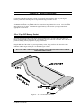
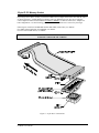
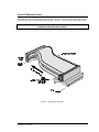
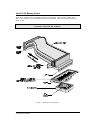
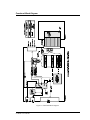


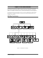


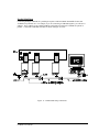


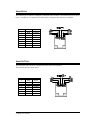
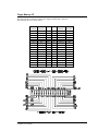


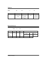
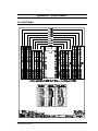
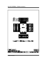
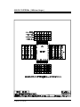
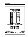

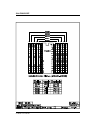
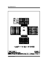


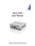

![E^YB?= ce``_bd VY\Uc V_b @QbQTYW] 4UReW BD](http://vs1.manualzilla.com/store/data/005839928_1-81490c34e940fa2480ecad1c81f1b8b0-150x150.png)