1
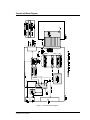
Chapter 4: Architectural Details
The previous chapters covered basic EPROM emulation. We designed several advanced features into
UniROM that allows it to do much more than simple emulation. This chapter discusses UniROM’s
architecture. Understanding UniROM’s architecture helps one to envision its potential and to understand
how some of the advanced feature work. Figure 8 shows a functional block diagram of UniROM’s
architecture. The following sections describe each item shown in the diagram. Some of this information
was covered in Chapter 1, but is repeated here for completeness.
Parallel IN/OUT
The PARALLEL port can be connected to a printer port on a PC. URLOAD, URTERM and the UniROM
Libraries can load, control and status UniROM through this connection.
This port is compatible with standard PC printer ports, BI-DIRECTIONAL printer ports and the newer ECP
and EPP ports in standard or bi-directional modes. IT DOES NOT SUPPORT CENTRONICS, EPP or
ECP PROTOCOLS.
URLOAD and the UniROM Libraries can load data at a sustained throughput of 70KBytes/second through
this connection. This interface is fully synchronous with full interlocked handshaking, making the system
immune to variations in parallel port driver capabilities, capacitive loading and cable length. Weak drivers,
excessive loading or excess cable lengths result in slower transfers, rather than data errors.
Serial IN
The SERIAL IN connector serves several purposes. It can be used to load, control and status UniROM. In
addition, it can be used to allow software debuggers or terminal emulation programs to communicate with
the target through one of our memory-mapped communications paths or the serial OUT port (see
CONSOLE PATHS below).
Serial OUT
The primary purpose of the SERIAL OUT port is to allow DAISY-CHAINING of multiple UniROMs. A
simple straight-through cable can connect the SERIAL OUT port from one UniROM to the SERIAL IN of
the next UniROM.
The Serial OUT port can also be connected to the target’s Serial port. If your target has a spare Serial port,
this console path would allow you to interface to the target kernel or monitor without modifications. This is
particularly useful if your kernel is already built and functioning through the serial port. UniROM can
simply intercept the serial line and debugging continues as usual.
UniROM User's Manual
18
RESET
The RESET output is a TTL/CMOS compatible output. It can be configured as a BIPOLAR driver or a
TRI-STATE driver. It should be connected to the target’s RESET circuitry.
UniROM can reset the target through a script command, a Library function or from an ASCII menu
selection. In addition, UniROM will automatically assert RESET during LOADS and VERIFIES from the
ASCII interface if AUTO-RESET is enabled (see the Chapter 12: ASCII Menu Reference).
INTERRUPT
The interrupt output is a TTL/CMOS compatible output. It can be configured as a BIPOLAR driver or a
TRI-STATE driver. It is normally connected to the target’s interrupt system while using URCOM or
VCOM for memory-mapped communications.
UniROM can interrupt the target through a script command, a Library function or from an ASCII menu
selection. In addition, URCOM or VCOM can automatically generate interrupts on RX, TX or BOTH.
To use this feature, simply configure the interrupt driver type and active level with the INTERRUPT
definition in a script file or through the Setup\Interrupt ASCII menu. Then connect Pin 4 of the feature
connector to your target’s interrupt line. Of course the target has to be configured to recognize the interrupt
and respond to it. This interrupt would usually be used to get the debug kernels attention.
CONTROL LINES
UniROM supports four user control lines. These may be individually set or cleared through script
commands, Library functions or the Target menu from the ASCII interface. One may use these to stimulate
or control the target. No configuration is necessary. Note that these lines are tri-stated when target power
drops below 4.0 Volts.
STATUS LINES
UniROM allows the user to monitor 4 different inputs from the target. These status line may be connected
to any TTL or CMOS signals on the target. Their state can be read from script commands, a Library
function or viewed from the Target menu in the ASCII interface. No configuration is necessary.
DUAL-PORT MEMORY
UniROM incorporates a dual-ported memory architecture. This allows full access to the emulation memory
without disturbing the target in any way. This feature is used to allow real-time memory watching, memorymapped communications through VCOM, and real-time memory READS and WRITES while the target is
executing out of this same memory space. Chapter 5 describes in detail the arbitration mechanisms used to
accomplish this transparency.
VCOM
The CPU within UniROM manages a memory-mapped Virtual UART called VCOM. VCOM formalizes
the use of DUAL-PORTED memory for Target <-> HOST communications. VCOM looks very much like
UniROM User's Manual
19
a standard, memory-mapped UART to the target. This makes it very easy to configure most remote monitor
or kernel based debuggers to communicate through UniROM instead of a target serial port, eliminating the
need to dedicate target resources for debugging. Chapter 6 describes the target side interface to VCOM in
detail.
URCOM
URCOM is a high performance hardware option board. It provides a memory-mapped communications
port that does not require WRITE cycles from the target. It interprets a special sequence of reads as a
request to send data to the HOST. Eliminating the need for write cycles has several advantages.
First, it guarantees that CONSOLE communication will work, regardless of the target design. UniROM is
plugged into an EPROM or FLASH socket on the target. Some targets are incapable of writing to this
space. Decode logic may lock out WRITES to this address space. Some targets will place uni-directional
buffers between the EPROM socket and the CPU data bus, making it impossible to WRITE to the socket.
Targets with EVEN/ODD interleaved EPROMs will often use a single chip select for BOTH EPROMs,
making it impossible to do BYTE level access to the EPROMs. This is reasonable for CODE fetches, but
disastrous for WRITEs. URCOM is immune to all of these issues.
Second, it does not rely on arbitrated accesses to emulation memory for proper operation. This allows one
to ignore arbitration configuration issues while configuring and testing the console path. It separates the
two issues to simplify initial system bring-up.
Third, it operates without a WRITE line, allowing full communications without giving the target WRITE
access to the code space. This provides more immunity to code corruption by a run-away application.
All of our debugger support files use the URCOM option.
Refer to the URCOM User’s Manual for complete details.
SERIAL MODE SELECT
The SERIAL IN port has several uses. The block diagram illustrates this concept with the “MODE
SELECT” switch. This shows that the SERIAL IN port can be “connected“ to any one of the following:
- Serial OUT port
- VCOM
- URCOM
- Binary Packet Protocol Interpreter
- ASCII Protocol Interpreter
The first three items are CONSOLE paths. The last two items are command interpreters. Each are
discussed below.
CONSOLE PATH
Console Paths manage the SERIAL HOST side access to HOST <-> target communications. The Serial
HOST port can be virtually linked to the Serial OUT port, a VCOM connection or the URCOM option
board.
UniROM User's Manual
20
Once a CONSOLE path is established, all characters from the SERIAL IN port are transferred to the
selected communications port (SERIAL OUT, VCOM or URCOM). All characters from the
communications port are transferred to the SERIAL IN port. UniROM becomes transparent and simply
hands-off characters between the two ports.
This mechanism provides a communications path between the HOST and target through UniROM.
Software debuggers, monitor programs and target applications can use this in place of dedicated target
hardware.
ESCAPE DETECTION
During CONSOLE connections, UniROM monitors the serial link for an ESCAPE sequence or a BREAK.
Either of these conditions will terminate the CONSOLE connection. A BREAK condition is declared if the
SERIAL IN RX line is held at a logic low for more than 10 milliseconds. An ESCAPE sequence is defined
by a lack of receive activity for at least 2 seconds, followed by three consecutive ‘+’ characters.
URLOAD and URTERM issue a BREAK when first started to insure that they can communicate with
UniROM.
If you are using a terminal emulator, you can issue a BREAK or send the ESCAPE sequence any time you
wish to return UniROM to COMMAND MODE.
BINARY PACKET PROTOCOL Interpreter
The BINARY PACKET PROTOCOL interpreter is the main interface to UniROM. It is a very robust
protocol with full error checking and recovery mechanisms.
URLOAD and the UniROM libraries use binary packets to communicate with UniROM. This interpreter is
responsible for receiving, verifying and acting on those packets. As the block diagram shows, this
interpreter is available from both the SERIAL and the PARALLEL port interfaces.
The BINARY PACKET PROTOCOL interpreter verifies the checksum on all packets it receives. In
addition, it verifies the packet contents to insure that each data in each field is within acceptable ranges for
that parameter. For example, if it receives a RESET command packet, it will check that the FLAG
parameter is less than 3. Valid values for this parameter are 0 (OFF), 1 (ON) or 2 (PULSE). If any check
fails, a failure code is returned to the HOST. Otherwise the command is completed and a result code is
returned.
UniROM User's Manual
21
ASCII PROTOCOL Interpreter
The ASCII PROTOCOL Interpreter makes UniROM compatible with ANY HOST with an RS-232
compatible serial port and a terminal emulation program. The ASCII interface contains all of the
intelligence necessary to display menus and interpret commands from the user. This permits the use of
simple terminal emulators on the HOST and eliminates the need for any dedicated HOST software.
In PC environments, one can use URTERM to access the ASCII interface from a SERIAL or a PARALLEL
port. In addition, ALL HOSTs (including PCs) can use their favorite terminal emulator on the SERIAL
port interface.
UniROM User's Manual
22
Functional Block Diagram
Figure 8 - Functional Block Diagram
UniROM User's Manual
23


![E^YB?= ce``_bd VY\Uc V_b @QbQTYW] 4UReW BD](http://vs1.manualzilla.com/store/data/005839928_1-81490c34e940fa2480ecad1c81f1b8b0-150x150.png)