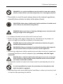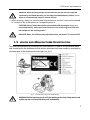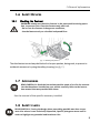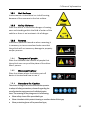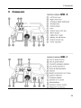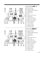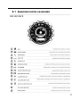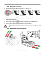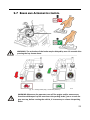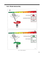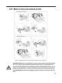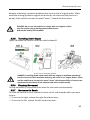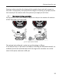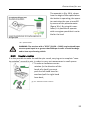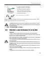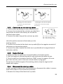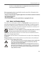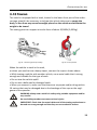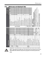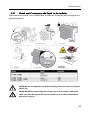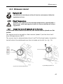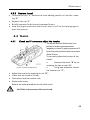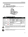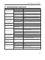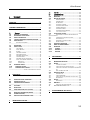
1
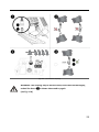
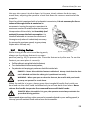
1 Ed. 1 This manual should always be readily available so that the vehicle operator can consult it immediately, and it must be kept for the entire duration of the vehicle’s life. © 2010 - The entire or partial reproduction and/or disclosure of this document is prohibited in any form without the written consent of the manufacturing company. The editing of the text, the illustrations, and the layout was realized by “Cormidi s.r.l.” The information and technical data were provided, checked and validated by the Cormidi Technical Office. The illustrations and technical data included in this manual are not binding: the manufacturer reserves the right to carry out modifications to the product without notice. 4175 Guardian Street Simi Valley, CA 93063 [email protected] www.mmdequipment.com P 800-433-1382 F 800-225-5579 2 FOREWORD Dear Customer, We would like to thank you for your confidence in us shown by purchasing a CORMIDI Minitransporter. This product was designed and built to last long and to be used safely. It is, however, absolutely necessary to carefully read this manual which describes the procedures for the optimal use of the vehicle: improper use may cause damage to the vehicle and injuries and/or damage to heath. Therefore, always keep this manual within easy reach so that it may be consulted at any time, before, during, and after use. If the vehicle is resold, do not forget to give it to the new owner with the minitransporter, since it contains the EC compliance certificate. We would also like to remind you that the illustrations contained in the manual correspond for the most part to the basic model and that our models are regularly improved and perfected in order to allow our Customers to get the most benefit from technological innovations: for this reason the characteristics and the information contained in this manual may have been changed recently. Therefore, please contact us should you have any problems. In any case, remember that for additional information you can always contact your representative/dealer, or you can contact us directly via telephone or email at [email protected]. If you have any doubts, it is better to ask rather than to proceed on your own. We leave you to read the manual and enjoy the vehicle! Best regards, Staff of CORMIDI Srl 2 1 General information 1 GENERAL INFORMATION 1.1 WARRANTY Your vehicle is guaranteed for 24 months from the date of its delivery and includes the replacement of parts that may be, in the opinion of our Technical Office, affected by construction defects. All components not constructed by the manufacturer, the parts used in the ground and the faults caused incompetence or carelessness, as well as consumables, labour and travel expenses, are excluded from the guarantee. The engine, instead, falls under the guarantee of the manufacturer of the engine itself, according to the conditions and terms provided for. The guarantee is immediately void if the vehicle is used for purposes other than those provided for by the Manufacturer, if it is damaged by the use of unauthorized accessories or if it is repaired using unsuitable spare parts. A Certificate of Warranty was supplied with the vehicle, which indicates the standards that govern assistance under warranty. We highly recommend reading the warranty form to fully understand the various rights and responsibilities. Collaborate with your sales representative when filling out the form and make sure it is filled out correctly, as the date, text, contents and other formalities (shipment within the time limit, etc.) represent the legal base for the right to warranty on the vehicle. -The warranty is void with immediate effect if the maintenance indicated in the manual is not carried out and certified. -The warranty is void with immediate effect if the vehicle is not maintained daily as indicated in the use and maintenance manual. -The warranty is void with immediate effect if it is not registered within 72 hours of commissioning. 3 1 General information 1.2 PURPOSE OF THE MANUAL This manual has been drawn up by the manufacturer and is an integral part of the vehicle: it was written in Italian, the native language of the manufacturer in accordance with section 1.7.4 of directive 2006/42/EC. The information contained herein is addressed to expert operators, with specific knowledge and competence in the field of use. The manual defines the purpose for which the vehicle was designed and constructed. To avoid incorrect manoeuvres with the risk of accidents, it is important to read this manual, in particular before the first use in order to become familiar with the main controls and functions. A constant observance of the information guarantees safety, operating economy, and a longer operating life of the vehicle. To emphasize the parts of text that must not be ignored, they have been highlighted in bold and preceded by symbols illustrated and defined below: READ CAREFULLY: invites you to read the manual carefully and thoroughly before performing the operations described. DANGER: indicates an imminently dangerous situation that may cause serious injuries or death if the instructions are not followed. On the vehicle the potential dangers are indicated with stickers featuring a yellow triangle with black edges containing a pictogram depicting the danger WARNING: indicates a potentially dangerous situation that may cause serious injuries or death if the instructions are not followed. On the vehicle the warnings are indicated with stickers featuring a yellow triangle with an exclamation mark and black edges. CAUTION: indicates a potentially dangerous situation that can provoke injury or damage to the vehicle if the instructions are not followed. On the vehicle situations requiring caution are indicated by stickers characterized by a blue circle with a pictogram. PROHIBITED: prohibitions that must be observed by all persons who interact directly and/or indirectly with the vehicle so that risks may be limited. 4 1 General information 1.3 DESCRIPTION OF THE VEHICLE The Series CMF Minitransporters are compact tracked vehicles that are equipped with equipment such as: dumper, self-loading equipment, cement mixer, miniloader, designed and manufactured for the exclusive use of transporting inert materials. To meet the various requirements of the market, the vehicle may be equipped with engines that have similar power but that have different brand names and characteristics. READ CAREFULLY: accurately determine the type of engine that has been installed in your vehicle, and read its manual to become familiar with it. 1.4 SAFETY INFORMATION READ CAREFULLY: the information contained in this manual is essential for your safety and for that of your co-workers! During the construction of this vehicle, every possible measure was taken to make your work safer. Caution is still irreplaceable: there is no better rule to prevent accidents. WARNING: The vehicle must always be operated by a competent and welltrained operator. Carefully read the information before using the vehicle or before performing maintenance and/or repairs. A few minutes of your time spent reading this manual will save you time and effort later on. Carefully read the warnings and information written on the signs on the vehicle and immediately replace missing or illegible ones. Observe all the regulations indicated. The vehicle was made exclusively for the transportation of inert material. Any other use is prohibited. PROHIBITED: It is strictly forbidden to use this vehicle for the transport of persons and/or animals. 5 1 General information PROHIBITED: It is strictly forbidden to use this vehicle to tow other vehicles, vehicles, and/or devices, not even temporarily or in an emergency situation. The vehicle is a tool for work: always observe the national regulations, especially those relative to safety at the place of work. OBLIGATION: always wear suitable work clothes and above all suitable work shoes. Always use protective hearing devices. WARNING: Never wear loose or fluttering clothing (scarves, ties) that could easily get caught in the moving parts. It is always advisable to have a first aid kit close at hand. Before turning on the engine, always be sure that there are no people, animals, or things that could be an obstacle in the work area. DANGER: Never use the vehicle inside enclosed areas because the gases emitted by the exhaust are lethal. OBLIGATION: Dispose of mineral oils and harmful products with respect for the environment and in accordance with the current regulations. All cleaning, adjustment and/or maintenance must be carried out in good environmental conditions and with adequate light, and always with the engine turned off. DANGER: Never refuel the vehicle when the engine is on or hot, in the proximity of flames or while smoking. Always keep the vehicle clean from lubricant and/or combustible residues. Be especially careful not come into contact with the overheated parts of the engine. It is strictly prohibited to remove the protections and safety devices with which the vehicle is equipped Avoid working under unsuitable physical conditions or when you are very tired: it is best to stop operating the vehicle. 6 1 General information DANGER: While working always be sure that the terrain has the required consistency and avoid working on the edge of embankments, ditches, or ravines or on excessively steep or uneven terrain. When putting away the vehicle take all precautions so that it cannot be moved or turned on by incompetent or incapable persons. CAUTION: Never leave the vehicle unattended while the engine is on, not even temporarily: when you leave the area, turn off the engine of the vehicle and put on the parking brake! DANGER: Never let children play with the vehicle, not even if it is turned off! 1.5 VEHICLE AND MANUFACTURER IDENTIFICATION The data that identifies the vehicle and the manufacturer is listed on the aluminium plate that is attached to the dashboard of the vehicle, whereas the frame number is stamped on the lower part of the dashboard on the right (see fig.1). fig. 1 – Identification plate (cod. C1094.14.10) WARNING: Before beginning work, verify the working order of the safety devices and replace any worn-out and/or broken parts immediately. 7 1 General information 1.6 SAFETY DEVICES 1.6.1 Blocking the Footrest WARNING: always use the drive footrest in the open position during operation, to prevent risks. Close the footrest only after use. - Do not use the footrest in dangerous conditions, - Use the footrest only on a levelled and paved floor fig. 2 – Blocking the footrest The drive footrest must always be blocked in the open position, during work, to prevent its accidental movement, by using the safety pin spring (see fig. 2.) 1.7 ACCESSORIES READ CAREFULLY: Read the instructions and the mode of use for the accessories that have been installed on your vehicle carefully. Refer to the instruction manual that was provided with them. See the manual of the specific accessory installed. 1.8 SAFETY PLATES READ CAREFULLY: During the design phase everything possible was done to prevent risks: where it was technically impossible, specific pictograms were used in order to highlight any potential and imminent risks. 8 1 General information Special stickers were made with signals and descriptions associated with pictograms to give higher importance to possible dangers, in accordance with standard UNI 9244-95 (E). PROHIBITED: it is strictly prohibited to remove the stickers and the safety plates with which the vehicle is equipped: immediately replace deteriorated and/or illegible ones. 9 1 General information 1.8.1 Hot Surfaces Invites caution in that there is a risk of burning because of the nearness to the hot surface. 1.8.2 Safety Distance Plate that warns of the serious danger of coming near and standing within the field of action of the vehicle as there is an imminent risk of danger. 1.8.3 Reverse Indicates a potential hazard as when reversing it is necessary to turn around and make sure that the vehicle will not cause any damage to property and/or persons. 1.8.4 Transport of people Plate that indicates the number of people that the vehicle can carry and the place of the driver. Max 1 person. 1.8.5 Disconnect battery Plate that shows where the battery cut-off device is located and how to use it. 1.8.6 Procedure for Caution This sticker inviting to be careful reminds the operator to adopt all safety precautions, above all regarding the use of protective equipment and individual protections. The meaning of the pictograms is the following: Wear safety shoes of the prescribed type. Wear a headset which protects hearing or another device of this type; Wear protective gloves of the prescribed type; 10 1 General information Read the manual before turning the vehicle on for the first time, each time an operator is changed, and in any case of doubt as to how the vehicle operates; • Do not remove the protections on the moving parts • Wear work clothes having the protections of the prescribed type; 1.8.7 Maximum Slopes Completely avoid working on terrains that have latitudinal slopes of more than 10° and longitudinal slopes of more than 20° to avoid the possibility of overturning with serious consequences for the safety of the operator. In any case, but especially when working on slopes, it is important that the terrain is solid and stable. 1.8.8 Procedure to deal with Slopes Sign that indicates in what way one must face downhill and uphill slopes to avoid serious consequences for the operator and for the vehicle in that there is the potential danger of overturning.. 1.8.9 Safety in the engine compartment Plate indicating to pay attention to the engine compartment. - before unscrewing the radiator cap, make sure that it has reached room temperature, then unscrew the cap carefully, in order to prevent the spilling of boiling liquid. 11 1 General information 1.8.10 Other signs The plate on the right (fig. 12-a) indicates that it is necessary to read the documentation before any intervention, to avoid technical problems (e.g. Manual attached to the engine). The plate on the right (fig. 12-b) indicates that you should read the use and maintenance manual before using the devices near this label, to avoid problems. 1.8.11 Moving parts Plate indicating that there are moving parts that could cause damage to objects and/or people. 1.9 ADMISSIBLE SLOPES fig. 4 – Maximum admissible slopes In figure 4 the maximum values for the latitudinal and longitudinal slopes of the terrain are shown on which it is possible to work. These conditions must never be exceeded to avoid the risk of overturning and breakage of the engine. DANGER: Always avoid working on terrain with slopes that are greater than those prescribed to avoid the possibility of overturning with possible serious consequences for the safety of the operator. In any case, but especially when working on slopes, it is important that the terrain is solid and stable. 12 1 General information 1.10 HYDRAULIC OUTLETS Plate that shows how to use the hydraulic outlets and how they are connected to the control levers on the dashboard. The number of levers may vary depending on the version (Spec 0; Spec 1; Spec 2; Spec 3;), therefore your vehicle may be different from the one shown in the figure. 13 1 General information 1.11 TECHNICAL DATA AND SIZE 14 Commands 2 COMMANDS 15 16 2.1 ANALOGUE-DIGITAL DASHBOARD 17 2.2 ELECTRICAL START-UP Put the battery cut-off device in position "2" (see fig. 11). fig. 6 – start-up Turn the key to position “1” (stable) to turn on the panel and thus the analogue-digital dashboard. Turn the key to position Turn the key to position (unstable) to activate the pre-heating unit. (unstable) to start the engine. WARNING: Disconnect the battery cut-off device every time the engine is turned off. 2.3 FORWARDS AND BACKWARDS fig. 7 – Forwards and backwards 18 2.4 LEFT LEVER fig. 9 – Left lever 2.5 RIGHT LEVER fig. 10 – Right lever 19 2.6 HORN AND BATTERY CUT-OFF LEVER fig. 11 – Horn button (top) - Disconnect battery (bottom) 20 2.7 BRAKE AND ACCELERATOR CONTROL WARNING: The activation of the brake may be delayed by max. 10 seconds after pressing the key shown above. fig. 12 – Parking brake (top) - Accelerator (bottom) WARNING: Whenever the operator turns off the engine and/or moves away from the minidumper he/she must insert the parking brake; just as at each engine start-up, before running the vehicle, it is necessary to release the parking brake. 21 2.8 POWER REGULATOR; fig. 13 – Power regulator 22 2.9 QUICK ATTACH AND RELEASE SYSTEM fig. 14 – Representation of the quick attach and release system of the tools WARNING: When the "quick attach" system is used, make sure that the vehicle is on a flat, clean and stable surface and that there is not dirt that may prevent the mechanism from working perfectly; also check that there are no objects or people within a radius of 10 metres from the vehicle that may be harmed/damaged due to the negligence of the operator in charge of the system. 23 fig. 14 b – quick attach couplings WARNING: The coupling may be hard to make; clean the area thoroughly, unload the levers (see fig. 14 b) as shown above and try again 24 Instructions for use 3 INSTRUCTIONS FOR USE 3.1 FIRST USE READ CAREFULLY: before using the vehicle you must read all of the instructions in this manual and the use and maintenance manual of the engine installed on your vehicle scrupulously. Furthermore, always keep it attached to the vehicle. fig. 15 – Position of the user manual The use and maintenance manual, together with the manual of the engine of the vehicle, must always easily be available and should be kept in the dedicated container attached to the vehicle (see fig. 15 above). The vehicle is normally delivered completely assembled and ready for use with an empty fuel tank. Fill the fuel tank, open the fuel tap and follow the start-up procedure described in the dedicated paragraph. 3.2 BREAKING-IN PERIOD The technology used during the construction of your vehicle does not require a breaking-in period. However, during the first period of use, it is necessary to use these precautions: During the first 50 hours, avoid using the engine at over 70 % of the total power. 25 Instructions for use READ CAREFULLY: Read the use and maintenance manual of the engine installed on your vehicle carefully and follow the instructions prescribed for its own breaking-in period. After the first 20 hours of operation, check the level of the hydraulic oil. During the first period of use, the tracks undergo an adjustment; therefore it is necessary, after the first 50 hours of operation, to carry out the regulation of the tension of the tracks. 3.3 ENGINE START-UP Every time you wish to start up the engine, always follow these indications scrupulously: Always start up the engine outside and be certain that there are no other persons in the vicinity of the vehicle and/or other impediments. Check that there is fuel in the tank and, if necessary, add some. Always insert the parking brake. WARNING: Before turning on the engine, always insert the parking brake to avoid any movements of the vehicle that may cause safety issues for the operator. Follow the specific procedure prescribed by the manufacturer of the engine shown in the attached instructions. When the engine is hot, in petrol operated engines, avoid inserting the starter. In diesel engines, there may be an automatic device for the valve raise that helps the start, it works automatically in the first seconds of start-up of the engine. 3.4 REFUELLING DANGER: Refuelling must always be done with the motor turned off! Do not smoke while refuelling or while handling fuel to avoid the risk of fire! Refuelling and/or movement of the fuel from one container to another must always be done outside, away from fires or from other heat sources. Always check that the type of fuel is the correct one, specified for the motor of your vehicle. Place the vehicle on a clean surface. 26 Instructions for use Unscrew the plug slowly. Pour the fuel into the tank slowly. Close the plug again tightly. Immediately dry any fuel leakage. Do not refuel when the vehicle is hot. WARNING: Do not refuel when the vehicle is hot, wait 2 hours after turning off the engine before refuelling. WARNING: Start up the engine only after making sure that there are no traces of fuel that have accidentally spilled out! WARNING: The fuel must be stored in compliance with the specific laws, in suitable places, away from heat sources, and in clean and well-closed suitable containers! OBLIGATION: Avoid the dispersion of fuel and/or fuel containers in the environment. Dispose of them according to the current laws and with respect for the environment. 3.5 DRIVING THE VEHICLE DANGER: Always avoid overloading the vehicle above the prescribed limits: during movement, an overload could create unforeseen structural variations and could cause the overturning of the vehicle with serious consequences for safety. WARNING: Where possible, try to avoid travelling on rocky or icy terrain, on rails and railway sections because they may damage the tracks and reduce their life. Also avoid driving over material that could ruin the tracks, such as sharp objects, pieces of metal, etc. that could get caught up in the tracks and cause them to break. At the start-up, adjust the number of rotations of the engine to the desired level by activating the accelerator lever, according to the required power (when the vehicle is loaded, you must bring the lever above the halfway mark between minimum and maximum). In some conditions, especially when the vehicle is loaded or going uphill, a loss of engine power may occur because of an engine overload; 27 Instructions for use this may also cause it to shut down. In this case, slowly release the drive command lever, adjusting the speed to a level that does not cause an overload of the propeller. Since the vehicle is equipped with a hydrostatic transmission, it is not necessary for the rotations of the engine to be at maximum for movements. Leaving the engine to operate at its maximum number of rotations does not improve the operation of the vehicle, but it certainly (and uselessly) increases the fuel consumption: it is therefore advisable to increase the rotations of the engine only where it is absolutely necessary (to proceed at maximum speed, to go up steep slopes with a full load, etc.). 3.5.1 Driving Position fig. 16 – Driving position While driving of the vehicle and during work, always use the driving footrest in an open position (see fig. 16), to prevent risks. Close the footrest only after use. To use the footrest you must place it correctly: Pull the safety pin spring that locks the footrest; Turn the footrest to the horizontal position; Pay attention to the spring pin, make sure that it fits into the hole. DANGER – Never drive with the footrest unblocked: always check that the footrest is blocked and that the safety pin is positioned correctly. WARNING – When you open or close the footrest, be careful with your hands: you may cut yourself or crush them. When the vehicle is in gear, always grasp the stronghold handle firmly with one hand and use the other hand simultaneously to activate both drive levers. Never release the handle to operate the command levers with both hands.. DANGER: When the vehicle is in gear, the operator must always maintain the prescribed driving position. Never speed when working, rather proceed at a speed adjusted to your walking speed, in this way you will maintain a safe control over the commands. 28 Instructions for use 3.5.2 Forward Gear To allow the vehicle to move forwards both drive levers must be activated simultaneously by pushing them forward. (see pag.18). Avoid going downhill in forward gear, refer to the paragraph: “Travelling on slopes”. 3.5.3 Reverse Gear To allow the vehicle to reverse you must activate both drive levers, pulling them back simultaneously. (see pag.18). Avoid going uphill in reverse gear, especially with a loaded vehicle, rather follow the procedure described in the paragraph: “Travelling on slopes”. DANGER: While in reverse gear, always check to see that there are no obstacles and/or persons in the vicinity. 3.5.4 Travelling up Slopes fig. 17 – a) going uphill; b) going downhill DANGER: Completely avoid working on terrains that have lateral slopes of more than 10° and longitudinal slopes of more than 20° to avoid the possibility of overturning with serious consequences for the safety of the operator. When travelling up or down slopes, especially when the vehicle is loaded, you must use this particular driving technique; Always face uphill slopes in forward gear; On extremely sloped terrain it is necessary to move with the engine at high speed (depending on the slope) minimizing the opening of the drive levers (see fig. 18 29 Instructions for use because, otherwise, cavitation problems may occur and the "engine-brake" effect would be missing (hydraulic engines are driven by the slope and they work as a pump): if the vehicle increases its speed "alone", release the drive levers. DANGER: Do not use the vehicle on a slope with an irregular surface. Use the vehicle only on hard ground without stones. Reduce the load by 50% downhill. 3.5.5 Travelling down Slopes Figure 18 shows the correct use of the vehicle downhill fig. 18 – Engine speed going downhill DANGER: Travelling down steep slopes with the engine at minimum speed and the drive levers at their maximum opening, will result in no “engine brake” effect and the vehicle may increase its speed "alone" with the possibility of serious consequences for the safety of the operator and other people nearby. 3.5.6 Stopping Movement To stop movement, release the drive levers for the tracks simultaneously. 3.5.7 Movement in Bends To allow the vehicle to turn, release the lever on the side towards which you want to turn: To turn to the right, release the right-hand drive lever; To turn to the left, release the left-hand drive lever. 30 Instructions for use Steering is determined by the slowing of the speed of one track with respect to the other. Consequently, the speed and the degree of steering are proportional to the intensity of the release and of the pressure you apply to each lever. 3.5.1 Movement during operation During operation the vehicle may be subject to a drop in the number of rotations of the engine due to a heavy load. fig. 18 – Engine speed overloaded The optimal value allowed, in order to avoid breakage, is 80rpm If the vehicle drops in rpm when overloaded, exceeding the allowed threshold, immediately loosen the potentiometer until the engine has started to turn at the same initial speed, maximum at 80 rpm. 31 Instructions for use The example in (fig. 18 b), shows how the engine loses speed when the bucket is operating; the operator maintains the rpm at max-80 by means of the potentiometer (figure 18 c). By using this command, it is possible to operate with an engine speed that is suitable for the load. 18 c– potentiometer WARNING: The versions with a "D722” (C1150 – C1200) engine should operate at a speed equal to or greater than 2000rpm in order to avoid breakage and to have a performing vehicle. 3.5.2 Counter-rotation It is also possible to make the vehicle spin round, carrying out a complete “counter-rotation” around its axis, in order to carry out manoeuvres in small spaces. To make a clockwise counterrotation (in the direction of the hands of a clock) you must push the left-hand lever forward and pull the right-hand lever back; fig. 19 – Clockwise counter-rotation 32 Instructions for use To make a counter-clockwise counter-rotation (in the opposite direction of the hands of a clock) you must push the righthand lever forward and pull the left-hand lever back. fig. 20 – Counterclockwise counter-rotation Using the counter-rotation manoeuvre often reduces the duration of the rubber tracks, especially if you do it on rough surfaces. WARNING: Manoeuvre to be carried out with the "potentiometer" at minimum being very careful; in fact, you could be thrown out of the driving position of the vehicle. 3.6 IF THE BATTERY IS DEAD 3.6.1 Precautions to connect and disconnect the start-up cables WARNING: • When starting the engine with the connecting cables, wear safety glasses. • If you start the engine, taking electricity from another vehicle, check that they are not in contact with each other. • To connect the start-up cables, start with the positive pole. To disconnect them, start with the negative pole (earth). • If a tool comes into contact with the positive pole of the vehicle, there is the risk of sparks. • Do not connect the connecting cables to poles with reverse polarity. For example, do not connect the negative pole on one vehicle and the positive pole on the other. The capacity of the start-up cables and the size of the clamps must be suitable for the size of the battery. • Check that there is no damage, cracks or corrosion on the cables and terminals. • The batteries of the vehicles must have the same capacity. 33 Instructions for use To connect, start with the positive pole (1) 3.6.2 To disconnect, start with the negative pole (1) Connection of the start-up cables 1. Turn the start-up switches on both vehicles to OFF. 2. Connect the terminal of the red start-up cable (A) to the positive terminal of the battery on the vehicle that has broken down. 3. Connect the other clamp of the red start-up cable BS = battery of working vehicle BP = battery broken vehicle MP = motor of broken vehicle (A) to the positive terminal of the battery on the working vehicle. 4. Connect the terminal of the black start-up cable (B) to the negative terminal of the battery on the working vehicle. 5. Connect the other clamp of the black start-up cable (B) to the engine block of the broken vehicle. 3.6.3 Engine Start-up 1. Make sure that the cables are connected safely to the battery poles. 2. Start the engine on the working vehicle and accelerate the motor to max. 3. Turn the switch on the broken vehicle to START to start the engine; If the engine does not start, wait at least two minutes before trying again. Do not turn the off the engine of the working vehicle, keep the engine at full speed and try again. 3.6.4 Disconnect the start-up cables • After starting the vehicle with the dead battery, disconnect the cables in reverse order with respect to the connection procedure. 1. Remove the clamp of the black start-up cable 34 Instructions for use (B) from the engine block of the broken vehicle. 2. Remove the clamp of the black start-up cable (B) from the negative pole of the battery of the broken vehicle. 3. Remove the clamp of the red start-up cable (A) from the positive terminal of the battery on the working vehicle. 4.Remove the clamp of the red start-up cable (A) from the positive terminal of the battery on broken vehicle. 3.6.5 BS = battery of working vehicle BP = battery broken vehicle MP = motor of broken vehicle Battery charge • Remove the cables from the positive and negative poles of the battery before setting the charge of the battery itself. Otherwise, an abnormal voltage can be applied to the alternator and cause damage. • If the battery overheats (the electrolyte temperature exceeds 45°C) stop the operation. • Stop the charging process as soon as the battery is charged. If you continue, the following defects may occur: - Battery overload - Reduction of electrolyte in the battery - Battery fault • Do not connect the connecting cables to poles with reverse polarity. For example, do not connect the negative pole on one vehicle and the positive pole on the other. A polarity inversion may damage the alternator. • The battery must be handled only when the cables have been disconnected (except for checking the electrolyte level and measuring the density of the electrolyte). 3.7 STOPPING AND PARKING If you move away from the vehicle and leave it unattended, always insert the parking brake and be sure that no unauthorized persons may turn it on 35 Instructions for use or move it. In the models which are equipped with one, always take out the start-up key and disconnect the battery. Before stopping the vehicle, it is preferable to position yourself on a flat paved surface, or on a flat and compact ground. -Using the accelerator lever, bring the engine down to its minimum number of rotations. -Insert the parking brake. -Turn off the engine. -Close the petrol valve (on the models that are equipped with one). 3.8 USING THE PARKING BRAKE The vehicle has a safety device called the “Parking brake” which prevents the vehicle from moving even if the towing controls are activated. This device serves to prevent the accidental movement of the vehicle in the absence of its operator; it also serves as an emergency stop when the operator may deem it necessary to instantaneously block the vehicle during operation. PROHIBITED: It is strictly forbidden to use the parking brake while the vehicle is moving to stop movement of the vehicle unless in case of emergency. Activation: press the button with the icon of the brake on the dashboard on the right of the analogue-digital device Deactivation: press the button on the dashboard on the right of the analogue-digital device Emergency brake: press the button with the icon of the brake on the dashboard on the right of the analogue-digital device. In the case that you may have to use the emergency brake, consider that this causes the drive mechanism to block instantaneously and may cause a loss of control of the vehicle. WARNING: after the intervention of the emergency brake, have the integrity and the working order of the device verified: a continued use of the vehicle with an inefficient device could be dangerous for your own safety and that of others. 36 Instructions for use READ CAREFULLY: Read the user’s instructions carefully for all accessories and/or tools that have been installed on your vehicle. Always refer to the manual which was provided with them and always keep it attached to this manual. 3.9 TRANSPORT WARNING: During transport, always level the vehicle to prevent oil or other liquids from spilling. If the vehicle must be transported, this must be done correctly to avoid danger to people and/or to the vehicle; if there is one on the vehicle, keep the bucket completely lowered during transportation. Because of the weight of the vehicle, it is not possible to move it or lift it manually. Therefore, it is necessary to use lifting equipment to load it onto a means of fig. 21 – Anchoring point transport. The vehicle is equipped with 4 hooks for lifting each one with a capacity of 8,000N (approx. 800 kg) for a total of 32,000N (3,200kg). The position of each hook is indicated with a label like the one shown in fig. 21 To do this safely, we recommend you use, as lifting means, 4 ropes with hook, EC compliant; the four front and rear ropes are 200 cm long Disconnect the battery by turning the battery cut-off device located inside the engine compartment; Attach the lifting hooks exclusively to fig. 22 – Lifting points the anchoring points that were prescribed by the manufacturer (fig. 22); WARNING: only lift the vehicle by using the dedicated eye-bolts: if you use other points the vehicle may break and fall, and may cause serious damage to people. 37 Instructions for use 3.10 TOWING The vehicle is equipped with a hook, located in the lower front part of the undercarriage; should it be necessary to tie/tow the vehicle take care to empty the body, or free from any excessive weight placed on the vehicle and minimize the weight to be towed. The towing point can support a tensile force of about 20,000N (2,000kg). 20,000 N fig. 24 – Anchoring points for towing Fig 25 correct position When the vehicle is stuck in the mud, or when you need to tow a heavy object, connect the rope as shown above. • While towing a vehicle with another vehicle, use a metal cable that is strong enough and suitable for the type of work. • Do not tow the vehicle uphill. • Do not use a deformed or damaged cable. • When you connect it, make sure that there are no people and/or things within 10 metres that may be damaged due to the breakage of the rope or the negligence of the operator. WARNING: always tow a vehicle in safety using suitable equipment and be very careful. An unsuitable procedure can cause serious injuries. IMPORTANT: Check that the metal cables and all the towing mechanisms to be used are strong enough and that they are not cracked or broken. 38 Instructions for use 3.11 STOWING WARNING: Do not stow the vehicle with a person or accessory on it WARNING: use a stowing method that is compatible with the weight of the vehicle and that complies with the current standards. Check the marking on the stowing accessory and acknowledge its LC 1. If there is no marking on the accessory, or if it is damaged, do not use it. WARNING: If you use other stowing methods, Cormidi does not guarantee the stowing of the vehicle. The driver must make sure that the angles (α) and (ß) are respected in the case of stowage and that no accessories change the path of the ropes changing the angles indicated by Cormidi. Angle Value in degrees fig. 26 – Anchoring points for stowage fig. 27 – Anchoring points for transport fig. 28 – Correct position ¹LC= Lift Capacity 39 Instructions for use Position the hooks correctly in the stowing points (see fig.28) -Be sure to correctly balance the load on each stowing point and do not overload it. Only use Cormidi-approved chains. Check the conditions of the floor of the trailer; it must be clean before loading the vehicle onto it If the floor of the trailer is made of steel, use non-slip mats to prevent the vehicle tracks from slipping. Check the LC¹ of the stowing points of the trailer; it must be at least equal to the recommended capacity LC¹ of the stowing accessories. Check the position and conditions of the stowing points of the vehicle. Only use the points indicated in this manual for the stowing and lifting of the vehicle. When stowing the vehicle, respect the angles indicated in the table (fig.26) provided by the manufacturer. Secure the vehicle to the floor of the means of transport by using the Cormidi approved chain (Cod. C0260.00.3) which can be purchased from authorized Cormidi dealers, connecting it to the points shown in figure 26. 3.12 STORAGE Whenever the vehicle must remain inactive for several months, it is necessary to store it correctly so that it will be in perfect working order when it is used again. Store it following all the instructions: Carry out all necessary repairs; Disconnect the battery, by acting on the battery cut-off device; Empty the fuel tank completely; Proceed with a careful cleaning and remove all mud, and/or organic residues; Proceed with all operations regarding the engine that are described in its own manual; Grease all points listed in the specific chapter; Place the vehicle in such a way that it is sheltered from atmospheric agents in stable conditions and on a flat surface; ¹LC= Lift Capacity 40 Maintenance Unplug the battery terminals and lubricate them with the correct grease Recharge the battery every two months; Remove the start-up key and keep it in a safe place. When putting the vehicle back into service: Grease all points listed in the specific chapter; Recharge the battery and reconnect it correctly; Insert the battery cut-off lever; Proceed with all operations regarding the engine that are described in its own manual; Check the oil level and add some if necessary. 4 MAINTENANCE DANGER: always carry out all maintenance operations with the engine off and with the start-up key not inserted. Good maintenance is required and is the secret to lower operating costs and to extend the life of your vehicle, keeping it up and running. In addition to regular maintenance on mechanical and hydraulic elements, it is good practice to periodically clean the vehicle and carry out thorough cleaning to remove all traces of mud. After each wash it is necessary to grease all parts subject to friction, as specified in the section “Greasing”. 4.1 MAINTENANCE INTERVALS To maintain the highest level of efficiency, and lengthen the life of the vehicle and in any case the warranty, it is necessary that maintenance is performed at regular and scheduled intervals. There is a table showing all the maintenance operations to be performed every 8 hours and the schedule of planned maintenance. 41 Maintenance 4.1.1 Maintenance and adjustment table WARNING: The maintenance is to be performed by a service centre authorized or approved by Cormidi, after the maintenance ask them to issue the receipt which will need to be kept for the purposes of continuity of the warranty. 42 Maintenance 4.2 ENGINE READ CAREFULLY: the instructions and the mode of use for the engine found in the specific manual attached. The vehicle that has been delivered to you may be equipped with a different engine for specific needs and/or markets. A correct maintenance is the best way to keep the engine of your vehicle so that it is always working at its highest efficiency and this will allow you to maintain low operation costs. For the maintenance of the engine, pay scrupulous attention to the attached manual that was given to you. OBLIGATION: When changing the engine oil, always use a suitable aspirator to remove the old oil. Always avoid the dispersion of oil and filters into the environment and dispose of them with respect for the environment and the regulations in force. Every 8 hours 4.2.1 Routine Maintenance Cleaning the vehicle Your vehicle must be thoroughly cleaned so that it can be efficient every time it is used. To ensure proper operation of the vehicle it is necessary to check the visible components such as jacks, hydraulic motors, hydraulic pump, oil tank and fuel oil, diesel fuel level meter, distributor and all the pipes present. WARNING: Do not throw water on the electrical parts of the vehicle. 4.2.2 Check for oil and/or fuel leakages Visually check if the piping and/or other components of the vehicle unfortunately allow the escape of liquids such as oil, fuel. 43 Maintenance 4.2.1 Check and if necessary add liquid to the radiator Check the level of liquid in the radiator daily in order not to operate with the engine at a high temperature WARNING: Do not open the cap without waiting two hours after turning the vehicle off; WARNING: Before unscrewing the radiator cap to check and/or add liquid, make sure that the temperature of the liquid is low in order to avoid burns and serious injuries. 44 Maintenance 4.2.1 Check the proper operation of the glow plugs It is certainly very important to check that the glow plugs in the vehicle, with diesel mo-tor, are efficient and fully functional. To do this, proceed as follows: Turn the key to position Turn to position to start the engine When the engine is running, observe the exhaust gas, if it is white, it is clear that the glow plug pre-heating system is not working cor-rectly. for 10 seconds fig. 31 – Check the glow plugs 45 Maintenance 4.2.2 Dual cartridge air filter Your vehicle may be equipped with a special dual cartridge air filter, which increases and improves the filtering power. fig. 26 - Dual cartridge air filter fig. 27– Exploded diagram of air filter Open the engine bonnet “A” (see fig. 26) Release the two tabs “1” ” (see fig. 27) on the right and left of the filter “B” Remove the cover "2"; Remove the cartridges “3” and “4” from the filter compartment Thoroughly clean the cartridges “3” and “4” Insert the cartridges “3” and “4” in the filter compartment “5” Close the cover “2” and replace the tabs “1” To clean the cartridge it is advisable to soak it in a container with oil or gasoline to remove the dirt. 46 Maintenance 4.3 HYDRAULIC CIRCUIT 4.3.1 Hydraulic Oil OBLIGATION: Do not dispose of the oil into the environment; follow the regulations in force. 4.3.2 Check Temperature DANGER: The hydraulic oil can reach high temperatures, especially after a day of work: avoid replacing the oil when it is hot to avoid the risk of burning yourself. 4.3.1 Check the level of hydraulic oil in the tank. To check the correct level of hydraulic oil, the vehicle must be placed on a flat surface. The engine must be started for a few minutes (about 5) so that the oil will have a temperature of 40°C. The correct level is obtained when the oil is at ¾ of the level meter, located on the left side of the dashboard near the air intake on the left (see fig. 26). Fig.28 correct level of hydraulic oil Fig.29 adding hydraulic oil 47 Maintenance 4.3.2 Restore Level Unscrew the cap “1” Restore the level adding specific oil into the opening “2” Replace the cap “1” Briefly operate the drive and command levers; Stop the engine and check that the oil level is at ¾ of the level gauge repeat the process. 4.4 TRACKS 4.4.1 Check and if necessary adjust the tension The correct tension of the tracks is important in order to guarantee their longevity: to check it, apply a pressure of 5 20mm kg on the track and check that the arrow is about 20 mm.. To correctly adjust the tension of the tracks: Remove the cover “B” by unscrewing the two screws “A”; fig. 30 -Track tension adjustment Using two wrenches, loosen the counter-nut “C”; Adjust the tension by working on nut “D”; Check that the arrow is 20 mm; Once done, lock the counter-nut; Replace the cover;. Repeat the same procedure on the other track. CAUTION: in the presence of 40 mm of mud. 48 Maintenance 4.4.2 Replacement DANGER: Never work with the vehicle raised on a jack or suspended, rather always place it upon suitable trestles that can maintain the weight of the vehicle before starting work. To replace the tracks proceed as follows: Raise the side of the vehicle on which you wish to work using hydraulic jacks or a crane; Position the vehicle on suitable trestles, and check to see that it is staZ ble; Remove the cover “B” by unscrewing fig. 31 - Replacement of tracks the two screws “A”; Using two wrenches, loosen the counter-nut “C” and completely unscrew both the counter-nut and nut “D”; Remove the track “E” starting from the front part “Z” Mount the new track lining it up with the teeth of the drive wheel “F”; Fit the front of the track onto the idle wheel “G”; Adjust the tension by working on nut “D”; Check that the arrow is 20 mm; Once done, lock the counter-nut “C”; Replace the cover. 49 Maintenance 4.5 GREASING 4.5.1 Grease all the points indicated. Grease all the greasing points, using a special greaser. Also, grease the drive lever using a can of spray grease. fig. 32 – Greasing points. 4.6 RECOMMENDED LUBRICANTS DANGER: before lubricating the vehicle, make sure you have: turned off the engine, activated the parking brake, put the vehicle on a flat surface and on stable and solid ground. OBLIGATION: Do not dispose of the oil and grease into the environment; follow the regulations in force. Do not pollute. 50 Inconveniences and Faults 5 INCONVENIENCES AND FAULTS Inconvenience Hydraulic oil is leaking. Cause Excessive oil level. Overheated oil. Insufficient oil level. Overheating. Solution Restore the level Turn off the vehicle and let it cool down Have the vehicle checked by a mechanic with specific competence Restore the level Have the vehicle checked by a mechanic with specific competence Restore the level Have the vehicle checked by a mechanic with specific competence Restore the level Insert the sleeves correctly Have the vehicle checked by a mechanic with specific competence Restore the level Turn off the vehicle and let it cool down The brake cable is broken. Have the cable replaced by a mechanic fault in the hydraulic circuits. Oil leak. The hydraulic commands do not respond correctly. Lack of pressure in the auxiliary hydraulic openings. Excessive oil temperature. Parking brake does not deactivate. The vehicle does not move. Excessive noise from the tracks during movement. The accelerator does not respond. The motor does not work correctly or makes an excessive amount of noise. The motor does not develop power. The motor does not start Excessive oil level. Fault in hydraulic circuits or in washers. Insufficient oil level. fault in the hydraulic circuits. Insufficient oil level. Sleeves not inserted correctly. fault in the hydraulic circuits. The brake is blocked. The parking brake is activated. Not enough oil in the hydraulic circuit. Move the vehicle backwards and forwards slightly and try again. Deactivate the parking brake Restore oil to the correct level parking brake active. Replace the tracks Fault in the hydraulic components. Incorrect track tension. Tracks broken or worn. Fault in the bearings or rollers. The accelerator cable is broken. Have the vehicle checked by a mechanic with specific competence Adjust the tension. Replace the tracks Have the vehicle repaired by a mechanic Various. The air filter is blocked. Various. Needs fuel. The start-up procedure is not correct. The battery is dead. Have the cable replaced by a mechanic Have the vehicle checked by a mechanic with specific competence Replace the air filter Have the vehicle checked by a mechanic with specific competence Refuel the vehicle Follow the correct procedure. Recharge or replace the battery 51 Attachment 6 SUMMARY FOREWORD .............................................................................. 2 1 GENERAL INFORMATION ................................................ 3 1.1 WARRANTY ................................................................... 3 1.2 PURPOSE OF THE MANUAL ....................................... 4 1.3 DESCRIPTION OF THE VEHICLE ................................... 5 1.4 SAFETY INFORMATION .............................................. 5 1.5 VEHICLE AND MANUFACTURER IDENTIFICATION ...... 7 1.6 SAFETY DEVICES ......................................................... 8 1.6.1 BLOCKING THE FOOTREST ......................................... 8 ..................................................................................................... 8 1.7 ACCESSORIES.............................................................. 8 1.8 SAFETY PLATES ........................................................... 8 1.8.1 HOT SURFACES ..................................................... 10 1.8.2 SAFETY DISTANCE .................................................. 10 1.8.3 REVERSE ............................................................... 10 1.8.4 TRANSPORT OF PEOPLE ............................................ 10 1.8.5 DISCONNECT BATTERY ............................................ 10 1.8.6 PROCEDURE FOR CAUTION ...................................... 10 1.8.7 MAXIMUM SLOPES ................................................. 11 1.8.8 PROCEDURE TO DEAL WITH SLOPES ........................... 11 1.8.9 SAFETY IN THE ENGINE COMPARTMENT ...................... 11 1.8.10 OTHER SIGNS ................................................... 12 1.8.11 MOVING PARTS ................................................ 12 1.9 ADMISSIBLE SLOPES................................................. 12 1.10 HYDRAULIC OUTLETS ............................................ 13 1.11 TECHNICAL DATA AND SIZE ................................ 14 .................................................ERRORE. IL SEGNALIBRO NON È DEFINITO. 2 COMMANDS .............................................................. 15 2.1 ANALOGUE-DIGITAL DASHBOARD .......................... 17 2.2 ELECTRICAL START-UP............................................... 18 2.3 FORWARDS AND BACKWARDS ............................... 18 ................................................................................................... 18 2.4 LEFT LEVER ................................................................ 19 2.5 RIGHT LEVER ............................................................ 19 2.6 HORN AND BATTERY CUT-OFF LEVER ...................... 20 ................................................................................................... 20 2.7 BRAKE AND ACCELERATOR CONTROL ..................... 21 2.8 POWER REGULATOR; ............................................... 22 2.9 QUICK ATTACH AND RELEASE SYSTEM ................... 23 3 3.1 FIRST USE.................................................................... 25 3.2 BREAKING-IN PERIOD .................................................... 25 3.3 ENGINE START-UP ................................................... 26 3.4 REFUELLING .............................................................. 26 3.5 DRIVING THE VEHICLE .............................................. 27 3.5.1 DRIVING POSITION ................................................. 28 3.5.2 FORWARD GEAR .................................................... 29 3.5.3 REVERSE GEAR ...................................................... 29 3.5.4 TRAVELLING UP SLOPES ........................................... 29 3.5.5 TRAVELLING DOWN SLOPES ..................................... 30 3.5.6 STOPPING MOVEMENT ............................................ 30 3.5.7 MOVEMENT IN BENDS ............................................ 30 3.5.1 MOVEMENT DURING OPERATION .............................. 31 3.5.2 COUNTER-ROTATION .......................................... 32 3.6 IF THE BATTERY IS DEAD ........................................... 33 3.6.1 PRECAUTIONS TO CONNECT AND DISCONNECT THE START-UP CABLES 33 3.6.2 CONNECTION OF THE START-UP CABLES..................... 34 3.6.3 ENGINE START-UP .................................................. 34 3.6.4 DISCONNECT THE START-UP CABLES .......................... 34 3.6.5 BATTERY CHARGE................................................... 35 3.7 STOPPING AND PARKING ....................................... 35 3.8 USING THE PARKING BRAKE .................................. 36 3.9 TRANSPORT .............................................................. 37 3.10 TOWING ............................................................... 38 3.11 STOWING.............................................................. 39 3.12 STORAGE .............................................................. 40 4 4.1 4.2 4.2.1 4.2.2 4.2.1 4.2.2 4.3 4.3.1 4.3.2 4.3.1 4.3.2 4.4 4.4.2 4.5 4.5.1 4.6 5 MAINTENANCE .......................................................... 41 MAINTENANCE INTERVALS ...................................... 41 ENGINE ..................................................................... 43 CLEANING THE VEHICLE .......................................... 43 CHECK FOR OIL AND/OR FUEL LEAKAGES .................. 43 CHECK AND IF NECESSARY ADD LIQUID TO THE RADIATOR 44 DUAL CARTRIDGE AIR FILTER .................................... 46 HYDRAULIC CIRCUIT ................................................. 47 HYDRAULIC OIL ..................................................... 47 CHECK TEMPERATURE ............................................. 47 CHECK THE LEVEL OF HYDRAULIC OIL IN THE TANK. ..... 47 RESTORE LEVEL ...................................................... 48 TRACKS ..................................................................... 48 REPLACEMENT........................................................ 49 GREASING ................................................................ 50 GREASE ALL THE POINTS INDICATED. ......................... 50 RECOMMENDED LUBRICANTS.................................. 50 INCONVENIENCES AND FAULTS.......................... 51 INSTRUCTIONS FOR USE ........................................ 25 52 Attachment 53 Attachment Note_________________________________________________________ _____________________________________________________________ _____________________________________________________________ _____________________________________________________________ _____________________________________________________________ _____________________________________________________________ _____________________________________________________________ _____________________________________________________________ _____________________________________________________________ _____________________________________________________________ _____________________________________________________________ _____________________________________________________________ _____________________________________________________________ _____________________________________________________________ _____________________________________________________________ _____________________________________________________________ _____________________________________________________________ _____________________________________________________________ _____________________________________________________________ _____________________________________________________________ 54 Attachment 55 EN OEM Rent alDi st r i but or 4175Guar di anSt r eet Si miVal l ey ,CA93063 i nf o@mmdequi pment . com www. mmdequi pment . com P8004331382 F8002255579