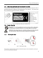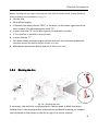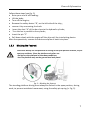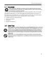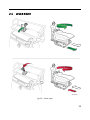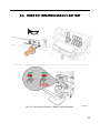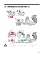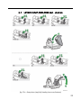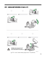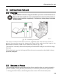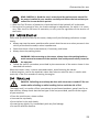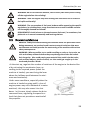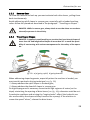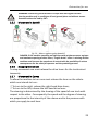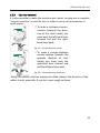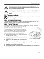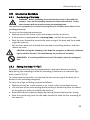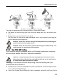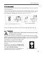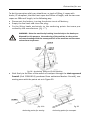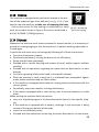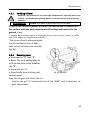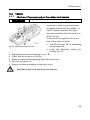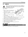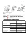
1
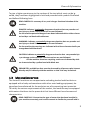
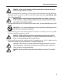
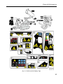
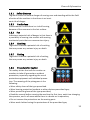
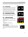
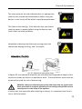
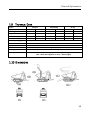
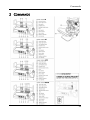
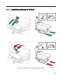
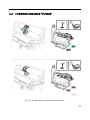
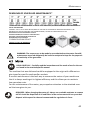
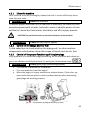
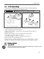
1 Ed. 1 This manual should always be readily available so that the machine operator may consult it immediately, and it must be saved for the entire duration of the machine’s life. © 2010 - The entire or partial reproduction and/or divulging of this document is prohibited in any form without the written consent of the manufacturing company. The editing of the text, the illustrations, and the paginations were realized by “Cormidi s.r.l.” The information and technical data were furnished, checked and validated by the Cormidi Technical Office. The illustrations and technical data included in this manual are non binding: the manufacturer reserves the right to carry out eventual modifications to its product without notice. 4175 Guardian Street Simi Valley, CA 93063 [email protected] www.mmdequipment.com P 800-433-1382 F 800-225-5579 2 INTRODUCTION Dear Customer, We would like to take this opportunity to thank you for your confidence in us shown by purchasing a CORMIDI Minitransporter. This product was designed and constructed for longevity and to be used with maximum reliability. It is, however, absolutely necessary to read this manual carefully in which the procedure for optimum use of the equipment is described: improper use may provoke harm to oneself and cause injury to persons and/or to one’s health. Therefore, always keep this manual within easy reach so that it may be consulted at any time, before, during, and after use. If the machine is resold, do not forget to give it to the new owner in that inside there is the EC compliance certificate. We would like to remind you that the illustrations contained in the manual correspond for the most part to the base model and that our models are regularly improved and perfected with the goal of allowing our customers to enjoy the maximum benefits of innovations in technology: for this reason the characteristics and the information contained in the present manual may have been varied recently. We ask you to contact us in case you should encounter difficulty. Remember for supplementary information you can always contact your sales representative/dealer, or you can contact us directly by telephone or by email at [email protected]. If there is any doubt, it is better to ask rather than proceed on your own. We leave you to your perusal of the manual and enjoyment of your machine! Staff CORMIDI Srl 2 General Information 1 GENERAL INFORMATION 1.1 WARRANTY Your machine is guaranteed for 24 months from the date of its delivery and includes the substitution of anything in particular that has resulted as, in the opinion of our Technical Office, affected by construction defects. Any part in particular that was not constructed by the manufacturer, parts used in/on terrain surfaces, and breakdowns caused by incompetence or carelessness, including fuelling, are excluded from the guarantee. The motor, instead, is covered under the manufacturer of the motor’s own warranty according to the foreseen conditions and terms. The guarantee immediately expires if the machine is utilized for uses different from those foreseen by the Manufacturer, if it is damaged by the use of unauthorized accessories or if it is repaired using unsuitable parts. With the machine a Certificate of Warranty was supplied which outlines the norms which regulate the service of assistance under warranty. We highly recommend reading the warranty form to fully understand the various rights and responsibilities. Collaborate with your sales representative when filling out the form and make sure it is filled out correctly, in that the text and the other formalities (shipment within the time limit, etc.) represent the legal base for the warranty on the machine. 1.2 GOAL OF THE MANUAL This manual has been drawn up by the manufacturer and is an integral part of the machine: it was written in Italian, the native language of the manufacturer (1.7.4 2006/42/CE). The information contained here within is addressed to expert operators, equipped with specific knowledge and competence in the sector of use. The manual defines the objectives for which the machine was designed and constructed. To avoid incorrect manoeuvres that risk accident, it is important to read this manual particularly before the first use to familiarize oneself with the principal commands and their functions. A constant observance of the information guarantees safety, economy of use, and a longer functional duration of the machine. 1 General Information To give a higher prominence to the sections of the text which must not be ignored, they have been highlighted in bold and preceded with symbols illustrated and defined following here: READ CAREFULLY: economy of use, and a longer functional duration of the machine. DANGER: indicates imminently dangerous situations that can provoke serious injury or death if the instructions are not followed. On the machine potential dangers have been indicated with a sticker characterized by a red band with white text. WARNING: indicates a potentially dangerous situation that can provoke serious injury or death if the instructions are not followed. On the machine the warnings are indicated with stickers characterized by an orange band with black text. CAUTION: indicates a potentially dangerous situation that can provoke injury or damage to the machine if the instructions are not followed. On the machine situations requiring caution are indicated by stickers characterized by a yellow band with black text. PROHIBITED: prohibitions that must be observed by all persons who interact directly and/or indirectly with the machine so that risks may be limited. 1.3 MACHINE DESCRIPTION The Series 85 machines are compact auto-unloading tracked vehicles that are equipped with a body and sometimes with other auto-loading equipment, designed and manufactured for the exclusive use of transporting inert materials. To satisfy the various requirements of the market, the machine may be equipped with motors that have similar power but that have different brand names and characteristics. READ CAREFULLY: Determine the type of motor that has been installed in your machine accurately, and read its manual to familiarize yourself with it. 2 General Information 1.4 SAFETY INFORMATION READ CAREFULLY: The information contained here is essential for your safety and for that of your co-workers! During the production of this machine, every possible measure was taken to make your work safer. Simple prudence, however, is essential: there is no better rule to prevent accidents. WARNING: The tool must always be operated by a competent and well-trained operator. Carefully read the information before using the machine or before performing maintenance and/or repairs. A few minutes of your time spent reading this manual will save you time and effort later on. Carefully read the warnings and information written on the signs on the machine and immediately substitute missing or illegible ones. Respect all regulations contained in these. The machine was made exclusively for the transportation of inert materials. Any other use is prohibited. . PROHIBITED: It is strictly prohibited to use this machine for the transport of persons and/or animals. PROHIBITED: It is strictly prohibited to use this machine to tow other machines, vehicles, and/or devices, not even temporarily or in an emergency situation. The machine constitutes a work instrument: always respect the national regulations, especially those relative to safety at the place of work. REQUIRED: Always wear suitable work clothes and above all suitable work shoes diligently. Always use protective hearing devices. WARNING: Never wear large or fly-away clothes (scarves, ties) that could easily get caught in the moving parts. It is always advisable to have a first aid kit close at hand. Before turning on the motor, always be sure that there are not any people, animals, or things that could be an obstacle in the work area. 3 General Information DANGER: Never use the machine inside enclosed areas because the gasses emitted by the exhaust are lethal. Every intervention for cleaning, tuning, and/or maintenance must be done under good environmental conditions and with adequate light, and always with the motor turned off. DANGER: Never refuel the vehicle when the motor is on or hot, in the proximity of flames or while smoking. Always keep the machine cleaned of lubricant and/or combustible residues. Pay careful attention to not come into contact with the overheated parts of the motor. PROHIBITED: It is strictly prohibited to remove protection and safety devices with which the machine is equipped Avoid working under unsuitable physical conditions or when you are very tired: in these cases interrupt your work. DANGER: While working always be sure that the terrain has the required consistency and avoid working on the edge of embankments, ditches, or ravines or on excessively steep or uneven terrain. When putting away the machine take all precautions so that it might not be moved or turned on by incompetent or incapable persons. CAUTION: Never leave the machine unattended while the motor is on, not even temporarily: when you leave the area, turn off the motor of the machine and put on the parking brake! DANGER: Never let children play with the machine, not even if it is turned off! 4 General Information 1.5 MACHINE AND MANUFACTURER IDENTIFICATION The data which identifies the machine and the manufacturer are listed on the aluminium plate that is affixed on the dashboard of the machine. The frame number is Impressed on the left rear fender (see fig. 1). fig. 1 - Identification Plate (cod. C1094.14.10) 1.6 SAFETY DEVICES PROHIBITED: it is strictly prohibited to use the machine with its safety devices and protection removed, blocked, or in any way made non functional. WARNING: Before beginning work, verify the working order of the safety devices and substitute any worn-out and/or broken parts immediately. 1.6.1 Blocking the Body fig. 2 – Blocking the body The machine is equipped with a device to block the body in the raised position and to prevent it from lowering accidentally. 5 General Information Before carrying out any repair maintenance work with the body raised, always block the piston following this procedure (see fig. 2): Lift the skip; Shut off the engine; • Remove the safety device "RED", in the back, on the lower right side of the skip; remove it by unscrewing the knob "B"; • Insert the slots "A" of the bar close to the hydraulic cylinder; • Turn the bar is parallel to the cylinder; • Insert the pin "C" Pull down slowly with the engine off the skip until the interlocking deviceAfterwards remove the device and put it back in its slot. Afterwards remove the device and put it back in its slot. 1.6.2 Blocking the Arm fig. 2a – blocking the arm If necessary, the machine is equipped with a device used to block the downloading arm in the raised position and prevents accidental lowering, as needed can be placed on the piston on the left or right in a similar manner. 6 General Information Follow these steps (see fig. 2): Raise your arm of self-loading; Lift the body; Turn off the engine; Remove the safety device "B", on the left side of the skip, ; remove it by unscrewing the knob Insert the slots "A" of the bar close to the hydraulic cylinder; Turn the bar is parallel to the cylinder; Insert the pin "C" Pull down slowly with the engine off the skip until the interlocking device After the operations, remove the device and place it back into place. 1.6.3 Blocking the Footrest CAUTION: Always use the platform of driving in the open position at work, to prevent any accidents. Close the platform only after use. -Do Not use the platform in hazardous conditions, -Use The platform only on the ground level and paved fig. 3 – Blocking the footrest The standing platform driving must always be locked in the open position, during work, to prevent accidental movement, using the safety pin spring (v. Fig. 3). 7 General Information 1.6.4 Blocking the Lift (“Hi-Tip”) fig. 3 a – Blocking the lift The raising device for the body for high unloading (Hi-Tip) can be blocked in a raised position to impede accidental movement, by using the safety pin Raise completely the skip; Turn off the engine; Remove the safety device "D", on the left side of the skip, remove it by unscrewing the knob B Insert the slots "A" of the bar near one of the two cylinders of the lift; Turn the bar is parallel to the Insert the pin "C" Pull down slowly with the engine off the lift until the interlocking device. After the operations, remove the device and place it back into place. 8 General Information 1.7 ACCESSORIES READ CAREFULLY: Read the instructions and the mode of use for the accessories that have been installed on your machine carefully. Refer to the instruction manual that was provided with them. The machine is furnished with equippment to make it possible to carry out normal maintenance operations. It is also equipped with a hydraulic force instrument: in the manual the instructions for its use have been furnished. Also, the machine the may also be equipped upon request with particular tools including: Cement mixer for mixing concrete; Auto-loading tools; Excavator; Demolition hammer. 1.8 SAFETY TAGS READ CAREFULLY: During the design phase everything possible was done to prevent eventual risks: where it was technically impossible, specific pictograms were resorted to in order to highlight eventual potential and imminent risks.Specific adhesive tags were made with signals and descriptions associated with pictograms to give a higher importance to possible dangers, in accordance with government norms UNI 9244-95 (E). PROHIBITED: it is strictly prohibited to remove the stickers and the safety plates which the machine is equipped with: immediately substitute deteriorated and/or illegible ones. 9 General Information fig. 4 – Position of the Safety Tags 10 General Information 1.8.1 Safety Distance Tag which alerts the serious danger of coming near and standing within the field of action of the machine in that there is an imminent risk of danger. 1.8.2 Hot Surface Invites caution in that there is a risk of burning because of the nearness to the hot surface.. 1.8.3 Fan Indicates a potential risk of danger in that there is a possibility of coming into contact with moving mechanical parts that can cause serious injury. 1.8.4 Crushing Tags which indicate a potential risk of crushing that may cause very serious injury or death. 1.8.5 Cutting Tags which indicate a potential risk of cutting that may cause very serious injury or death. 1.8.6 Procedure for Caution This safety sticker that calls for caution remember to take all precautions accident prevention, especially regarding the use of protective equipment and individual prevention. The meaning of the pictograms is the following: • Wear safety shoes of the type prescribed. • Wear hearing protection headsets or other devices prescribed type; • Wear protective gloves of the type prescribed; • Read the manual before running the machine the first time, each time changing the operator, and in all cases where there is a doubt on its operation; • Do not remove the protections on the moving parts • Wear work clothes having the protections of the prescribed type; 11 General Information • Do not adjust and / or remove and / or assembly parts during the running 1.8.7 Maximum Slopes Completely avoid working on terrains that have latitudinal slopes of more than 10° and longitudinal slopes of more than 20° to avoid the possibility of overturning with serious consequences for the safety of the operator. In every case, but especially in the case of slopes, it is important that the terrain is solid and stable. 1.8.8 Modo di Affrontare le Pendenze Nameplate indicating the way for to avoid serious consequences to the user and the machine as there is a potential danger of tipping. . 1.8.9 Safety in the engine place Name plate indicating to pay attention in the engine place Are given the following directions from left to right: - No adjust and / or modify the parts during the running, - Do not remove the safety guard - Do not touch - Do maintenance during the running 1.8.10 Other Tags The label on the side (fig. 12-a) indicates that it is necessary to read the documentation before any intervention, to avoid technical problems (ex. Manual attached to the engine). 12 General Information The name plate on the side indicates that it is appropriate, read the user manual and maintenance before using the devices in the vicinity of the plate to avoid disappointment. . The label on the side (fig. 12-b) indicates that you should read the owner's manual before using the devices next to this label, to avoid problems. Nameplate indicating that there are moving parts that could cause damage to thing and / or people. ADMISSIBLE SLOPES fig. 20 – Maximum admissible slopes In figure 20 the maximum values for the latitudinal and longitudinal slopes of the terrain are shown on which it is possible to work. These conditions must never be surpassed to avoid the risk of overturning. . DANGER: Always avoid working on terrain with slopes that are greater than those prescribed to avoid the possibility of overturning with possible serious consequences for the safety of the operator. In every case, but especially when working on slopes, it is important that the terrain is solid and stable. 13 General Information 1.9 TECHNICAL DATA Model Type Mass [kg] Engine Power [kW] - (cv) Max speed [km/h] (mph)capacity [kg] Load Start-up Accelerator Trasmission Parking Brake Battery Dumper 10.85 13.85 560 540 Diesel petrol 7,2 (9,8) 9,3 (12,6) 5.3 (3.3) 6,3 (3.9) Self-loading Hi-Tip 10.85 13.85 10.85 13.85 650 640 670 Diesel petrol Diesel petrol 7,2 (9,8) 9,3 (12,6) 7,2 (9,8) 9,3 (12,6) 5.3 (3.3) 6,3 (3.9) 5.3 (3.3) 6,3 (3.9) 800 Electric Manual command lever Hydrostatic Mechanical 12V - 45Ah with negative at mass – petrol engine 12V - 55Ah with negative at mass – diesel engine 1.10 DIMENSIONS 14 Commands 2 COMMANDS 15 2.1 FORWARD AND BACK "SPEED" fig. 23 – Forward (top) - Reverse (bottom) "speed" 16 2.2 FORWARD AND BACK "POWER" fig. 23 – Forward (top) - Reverse (bottom) "power” 17 2.3 LEVER LEFT fig. 24 – Lever left 18 2.4 LEVER RIGHT fig. 24 – Lever right 19 2.5 HORN BUTTON AND LEVER CUT-BATTERY fig. 26 – Horn button (above) - Battery switch (bottom) 20 2.6 PARKING BRAKE LEVER AND THROTTLE fig. 25 – Parking brake (above) - Throttle (bottom) WARNING: Whenever the operator turns off the engine and / or away from minidumpers you must enter the parking brake; as well as at each engine start, before starting off, necessarily mandatory release the parking brake 21 2.7 LEVER DUMP AND ARM SELF - LOADING fig. 27 a - Dump lever (top) Self-loading lever arm (bottom) 22 2.8 LEVER BUCKET ROTATORY LIFT AND HI-TIP fig. 27 b – Lever bucket rotatory (top) Lever Hi - Tip (bottom) 23 Instruction for use 3 INSTRUCTION FOR USE 3.1 FIRST USE READ CAREFULLY: Before using the machine you must read all of the instructions in this manual and the user’s and maintenance manual of the motor installed on your machine scrupulously. Furthermore, always keep it attached to the machine. fig. 28 – Container for manuals The owner's manual and main-tenance, together with the manual of the engine of the machine, must be always easi ly availa-ble and should be kept in the dedicated container fixed on the machine ( see the fig. 28) The machine is normally delivered completely assembled and ready for use with an empty fuel tank. Fill the fuel tank, open the fuel tap and follow the start-up procedure described in the appropriate paragraph. 3.2 BREAKING-IN PERIOD The technology used during the construction of your machine does not require a break in period. However, during the first period of use, it is necessary to use these precautions: During the first 50 hours, avoid using the motor at over 70 % of the total power. 24 Instruction for use READ CAREFULLY: Read the user’s manual and the maintenance manual for the motor installed in your machine carefully and follow the instructions prescribed for its own break in period. After the first 20 hours of operation, check the level of the hydraulic oil in the tanks. During the first period of use, the tracks undergo an adjustment, for which it is necessary, after the first 50 hours of operation, to carry out the regulation of the tension of the tracks. 3.3 MOTOR START-UP Every time you wish to start up the motor, always verify the following indications scrupulously: Always start up the motor outside and be certain that there are no other persons in the vicinity of the machine and/or other impediments. Check that there is fuel in the tank and, if necessary, add some. Always insert the parking brake. WARNING: Before turning on the motor, always insert the parking brake to avoid eventual movement of the machine that could present safety issues for the operator. Follow the specific procedure prescribed by the constructor of the motor shown in the attached instructions. When the motor is hot, in petrol operated motors, avoid inserting the starter. In diesel engines, can be an automatic valve that helps to raise the start, it works automatically in the first seconds of starting the engine. 3.4 REFUELLING DANGER: Refuelling must always be done with the motor turned off! Do not smoke while refuelling or while handling fuel to avoid the risk of fire! The supply and / or transfer of fuel must always be performed outdoors, away from fire or heat sources. Always check that the fuel type is the one prescribed, specific to the engine of your machine. • Place the machine on a clean surface. • Unscrew the cap slowly. • Pour the fuel in the tank slowly. • Screw the cap tightly. Dry immediately with any fuel leakage. • Do not fill with hot machine 25 Instruction for use WARNING: Do not fill with hot machine, wait 2 hours (two hours) after turning off the engine before the refueling! WARNING - Start the engine only after making sure that there are no traces of fuel spills accidentally! WARNING - The conservation of fuel must be done while respecting the specific regulations, in suitable places, away from heat sources and in suitable containers thoroughly cleaned and closed! REQUIREMENT: Avoid release to the environment fuels and / or containers, but please do so in an environmentally and local regulations. 3.5 DRIVING THE MACHINE DANGER: Always avoid overloading the machine above the prescribed limits: during movement, an overload could create structural variations that were not foreseen and could provoke the overturning of the machine with serious safety consequences. WARNING: Where possible, try to avoid travelling on rocky or icy terrain, on rails and railway sections because they may damage the tracks and reduce their longevity. Also avoid passing over material that could ruin the tracks, such as sharp objects, pieces of metal, etc. that could get caught up in the tracks and provoke a break. At the start-up, regulate the number of rotations of the engine to the desired level by activating the accelerator lever, according to the required power (when the machine is loaded, you must bring the lever above the halfway mark between the minimum and maximum). Under some conditions, especially when the machine is loaded or going uphill, a loss of engine power may occur because of a motor overload; this may also cause it to shut down. In this case, slowly release the drive command lever, regulating the speed to a fig. 29 – Driving position level that does not provoke an overload of the propeller. 26 Instruction for use Your machine is equipped with a hydrostatic transmission, so, it is not necessary that the rotations of the engine be at maximum for the displacement. Leave the engine operating at its maximum number of rotations does not improve the functioning of the machine, rather, it certainly (and uselessly) increases its fuel consumption: it is advisable, therefore, to increase the rotations of the engine only where it is absolutely necessary (to proceed at maximum speed, to address steep slopes with a full load, etc.). . 3.5.1 Driving Position During the driving of the machine and during the work, is necessary utilize the footrest platform in open position, always (see fig. 29), to prevent risks. Close the footrest platform only after use. • Pull the safety pin spring that locks the platform; • Turn the footrest to the horizontal position; • Pay attention to the spring pin, make sure that it fits into the hole. DANGER – Never drive with the footrest unblocked: always verify that the footrest is blocked and that the safety pin is positioned correctly. WARNING – When you open or close the footrest, be careful with your hands: you may cut yourself or crush them. When the machine is in gear, always grasp the stronghold handle firmly with one hand and use the other hand simultaneously to activate both drive levers. Never release the handle to operate the command levers with both hands. DANGER: When the machine is in gear, the operator must always maintain the prescribed driving position. Never speed when working, rather proceed at a speed adjusted to your walking speed, in this way you will maintain a safe control over the commands. 3.5.2 Forward Gear To allow the machine to advance one must activate both drive levers simultaneously by pushing them forward. Avoid addressing downhill slopes in forward gear, refer to the paragraph: “Travelling on Slopes”. 27 Instruction for use 3.5.3 Reverse Gear To allow the machine to back up you must activate both drive levers, pulling them back simultaneously. Avoid addressing uphill slopes in reverse gear, especially with a loaded machine, rather follow the procedure described in the paragraph: “Travelling on Slopes” . DANGER: While in reverse gear, always check to see that there are no obstacles and/or persons in the vicinity. 3.5.4 Travelling on Slopes DANGER: Completely avoid working on terrains that have lateral slopes of more than 10° and longitudinal slopes of more than 20° to avoid the possibility of overturning with serious consequences for the safety of the operator. fig. 30 – a) a) going uphill; b) going downhill When addressing sloped segments, especially when the machine is loaded, you must use this particular driving technique (see fig. 30): Always address the uphill slopes in forward gear; Always address the downhill slopes in reverse gear. On high slope ground is necessary to work with high regimen of motor (as the slope) minimizing the opening of drive levers (see fig. 44); otherwise could be verify cavitation problems and missing the “engine-brake” effect (the hydraulic motors are forced by the slope and they function like a pump): if the machine increase the speed “alone”, release the drive levers. 28 Instruction for use WARNING: Avoid using the machine on a slope with not regular surface. Use the machine only in conditions of hard ground place and without stones. Downhill reduce the load by 50% 3.5.5 Movement in dowhill fig. 31 – Motor regimen going downhill DANGER: if the machine travelling on high slope with minimum motor regimen and maximum opening of drive levers, “engine brake” effect is missing and the machine coud increase the speed out of control with the possibility of serious consequences for the safety of operator and the proximity persons. 3.5.6 Stopping Movement To stop movement one must release the drive levers for the tracks simultaneously. 3.5.7 Movement in Curves To allow the machine to turn one must release the lever on the side to which one intends to turn: To turn to the right, release the right-hand drive lever; To turn to the left, release the left-hand drive lever. The steering is determined by the slowing of the speed of one track with respect to the other. Consequently the speed and the degree of steering are proportional to the intensity of the release and to the pressure with which you apply to each lever. 29 Instruction for use 3.5.8 Counter-rotation It is also possible to make the machine spin round, carrying out a complete “counter-rotation” around its axis, in order to carry out manoeuvres in small spaces. To make a clockwise counterrotation (towards the direction of the clock hands) you must push the left-hand lever forward and pull the righthand lever back; fig. 32 – Controrotazione oraria To make a counter-clockwise counter-rotation (towards the opposite direction of clock hands) you must push the right-hand lever forward and pull the left-hand lever back. fig. 33 – Controrotazione antioraria Using the counter-rotation manoeuvre often reduces the duration of the rubber tracks, especially if you do it upon rough surfaces. 30 Instruction for use 3.6 STOPPING AND PARKING WARNING: If you move away from the machine and leave it unattended, always activate the parking brake and be sure that no unauthorized persons may turn it on or move it. In the models which are equipped with one, always take out the start-up key and unplug the battery. Before stopping the machine, it is preferable to position yourself on a flat paved surface, or on a flat and compact ground. Using the accelerator lever, bring the motor down to its minimum number of rotations. Insert the parking brake. Turn off the engine. Close the gas tap (on the models that are equipped with one). 3.7 USING THE PARKING BRAKE The machine has a safety device nominated as the “Parking Brake” which impedes the machine from moving even if the towing commands are activated. This device serves to impede the accidental movement of the machine in the absence of its operator; it also serves as an emergency stop when the operator may deem necessary to have an instantaneous block of the machine during work. PROHIBITED: It is strictly prohibited to use the parking brake while the machine is moving to arrest movement of the machine unless in case of emergency. To activate: Pull the lever lightly towards yourself and move it to the left making it go out of its slot and then let it go: the brake will insert itself automatically. To deactivate: Pull the lever towards yourself decisively and lightly and move it to the right hooking it into the special slot to block it: the brake has been deactivated. WARNING – If, when trying to deactivate the brake, the lever resists noticeably, avoid forcing the mechanism in that the wheel may block. Before deactivating the brake, move the machine forward and backward a bit until you have obtained the unblocking of the device. Emergency Brake: the parking brake serves also as a brake in emergency situations. To carry out an emergency brake, pull the lever towards yourself lightly, move it towards the left making it come out of the slot and let it go: the brake will insert itself automatically. 31 Instruction for use DANGER: In the case that you may have to use the emergency brake, consider that this causes the drive mechanism to block instantaneously and may cause a loss of control of the machine. WARNING: After the emergency brake intervention, have the integrity and the working order of the device verified: a continued use of the machine with an inefficient device could be dangerous for your own safety and that of others. 3.8 TRANSPORTING LOADS PROHIBITED: It is strictly prohibited to surpass the load capacity limits indicated in the table on page 15. 3.8.1 Construction Body (Dumper) The machine is equipped with a “dumper” type body to transport inert and solid materials, suitable mainly to be used for construction work. 3.8.2 “Farming” Type Body” Upon request, your machine may be fitted, in place of the “dumper” type body, with a body that has sides that can be opened, and is suitable to transport farming materials. The opening of the sides allows one to enlarge the loading surface to be able to transport cumbersome objects. To obtain a larger loading surface, work with one side at a time as follows (see fig. 56): Open two anterior hooks “C”, lower the anterior side “D” and take it out;; Loosen the two wheels “A” positioned under the loading surface; fig. 34 – Farming type body Take out the two supports “B” from their housings; Open the posterior hook “E” and lower the left lateral side “F” making coincide the notches of the supports in the holes “G”; Repeat the operation on the other side; Be sure that the sides are blocked and position the load so that it will not fall: if possible tied it. 32 Instruction for use 3.9 UNLOADING MATERIAL 3.9.1 Overturning of the Body WARNING - Before unloading, be certain that the terrain is flat, solid and compact. Carry out the dumping manoeuvre slowly and uniformly. Do not move forward with the machine during the dumping phase. Your machine is equipped with a hydraulic dumping device for the body which allows for the unloading of material. To carry out the dumping manoeuvre: Position yourself on a level, solid, and compact surface or terrain; If the machine is equipped with a farming body, unblock the anterior side; Push the lever forward to provoke the overturning of the body and the unloading of the material; Pull the lever back until the body has returned to travelling position, and then release the lever CAUTION: During the unloading, if the body hits up against an obstacle, avoid moving the machine forward: this could damage the junctions of the body! PROHIBITED: It is strictly prohibited to travel if the body is not in its resting position. 3.9.2 Raising the Body (“Hi-Tip”) On request the machine may be equipped with a hydraulic device to raise the body during the unloading to allow for unloading in containers or tubs with high walls, named “Hi-Tip”. To unload material normally, use the lever for the overturning of the body (as indicated in the preceding paragraph). To carry out a high unloading, proceed as follows: Position yourself on a level surface or on a level, solid, and compact terrain; Use the lever of the auto-loading device pushing it forward to place the shovel on the ground in order to stabilize the machine; Raise the body to the desired height by pushing forward the lever for raising; Push the overturning lever for the body forward to allow for the unloading of the material. 33 Instruction for use fig. 34 b – Position for high unloading To bring the body back to a driving position, proceed as follows: Pull back the overturning lever and bring the body back to a horizontal position; Release the command lever for the body Pull the lever for raising the body backward until it has reached the driving position; Release the raising lever. DANGER: Never carry out the raising of the body without first stabilizing the machine with the auto-loading shovel. DANGER: Never, for any reason, activate the raising lever while driving. You could provoke the overturning of the machine 3.9.3 Use of the Self-loading Your machine may be equipped with a self-loading mechanism consisting of an anterior bucket that has a hydraulic command. . CAREFUL: During movement the auto-loading device must remain raised above the surface of the land to avoid collision with the terrain and must be in a position that does not obstruct visibility. Loading: To be able to load the body using the auto-loading tool, you must follow this procedure: advance the machine towards the pile of material maintaining the benna in a horizontal position; raise the shovel by pulling the lever towards yourself until you have 34 Instruction for use poured the contents into the body. Repositioning: Push the lever forwards until the bucket has lowered to the correct height from the ground. Floating (auto-levelling): the auto-loading tool may also be used to function as an auto-levelling device, useful, for example for levelling ground. To block the bucket in the floating position you must push the autoloading lever forward past the lowering position until you have heard a click (the lever remains in stable position). CAREFUL: During the driving and movement of the machine, the self-loading device must not remain the the floating position. 3.10 SUPPLEMENTARY HYDRAULIC COMMAND Some versions may be equipped with a hydraulic force instrument for the command of auxiliary equipment. The hydraulic force instrument is composed of two openings with rapid transmission of standard type, indicated by the letters “A” and “B”, situated on the right side of the dashboard. To obtain hydraulic oil pressure on the openings you must work the auxiliary command lever. To obtain pressure on the “A” opening, push the lever forward. To obtain pressure on the “B” opening, pull the lever backward, toward yourself. READ CAREFULLY: Read the user’s instructions carefully for all accessories and/or tools that have been installed on your machine. Always refer to the manual which was provided with them and always keep it attached to this manual. 35 Instruction for use 3.11 ACCESSORIES Your machine can be equipped with some additional devices that make it more complete. To the side is shown the position of the 12V DC power outlet ( see fig. 58) that provides power for operation of electrical devices with additional features highlighted by the close label ( see fig. 35). fig. 35 – external charging socket 12 V fig. 36 – battery recharge Connect the cables to the battery terminals to recharge (see sidebar, fig. 36). 3.12 TRANSPORT WARNING: During transport, always position the machine levelly to avoid the spilling of oil or other liquids If the machine needs to be transported, one must proceed correctly to avoid dangers to persons and/or to the machine, if there is any on the machine, keep down completely the bucket during the transport. Because of the weight of the machine, it is not possible to move it manually. Thus, it is necessary to use suitable means of lifting to load it onto a means of transport. The machine is equipped with 4 hooks for lifting each one with a capacity of 7.000N (700kg) for a total of 28.000N (2.800kg). The position of each hook is indicated with a fig. 37 – Anchoring point label like the one shown in the fig. 62 36 Instruction for use To do this operation safely you should use, as tools of lifting, 4 ropes with hooks, CE compliant; the two front ropes are 200cm of length, and the two rear ropes are 200cm of length, in the following way: Disconnect the battery, turning the device to cut off battery; Empty the fuel tank and close the plug; Fix the lifting hooks exclusively to the anchoring points that were prescribed by the manufacturer (fig. 37); WARNING: Raise the machine by hooking it exclusively to the hooks predisposed for this purpose: the anchoring of the machine in other points can cause breakage with the consequent fall of the machine and can cause serious harm to persons. fig. 38 – Anchoring points to lift the machine Stick firmly to the floor of the means of transport through the chain approved Cormidi (Cod. C0260.00.3) purchased from authorized dealers Cormidi), connecting more with the points set as in Figure 39. fig. 41 b Anchoring points for towing fig. 3937 Anchoring points for transport Instruction for use 3.13 TOWING The machine is equipped with tow hooks, located at the bottom of the undercarriage, front abd rear (see fig. 41 b); if you need to tow the machine, to take care of emptying the body. Each anchor point for the towing is evidenced by a label fig. 40 – Anchoring point for towing with the symbol shown in figure 40 and can withstand a pull of 10.000N (1.000kg approx). 3.14 STORAGE Whenever the machine must remain inactive for several months, it is necessary to provide a correct garaging so that the machine is in perfect working order when it is used again. In particular one must carry out storage by following all of these instructions: Carry out all necessary repairs; Disconnect the battery, turning the device to cut off battery; Empty the fuel tank completely; Proceed with a careful cleaning and remove all mud, and/or organic residues carefully; Proceed with all operations regarding the motor that are described in its own manual; Carry out a greasing of all points listed in the specific chapter; Place the machine in such a way that it is sheltered from atmospheric agents under stable conditions and on a flat surface; If the machine is equipped with batteries, unplug them and lubricate with the correct grease; Periodically, every two months, recharge the battery; If the motor is equipped with a start-up key, take it out and conserve in a safe place. When putting the machine back into service: carry out all greasing again in all prescribed points found in the specific chapter; If the machine is equipped with a battery, recharge it and reconnect it being certain of the correct polarity of the ends; Insert the cut off battery lever; Proceed with the operations concerning the motor described in its own manu- 38 Maintenance al; Check the oil level and add some if necessary. 4 MAINTENANCE DANGER: always carry out all maintenance operations with the motor off and with the start up keys not inserted. Good maintenance is required and is the secret to low operating costs and extend the life of your machine, keeping it up and running. In addition to regular maintenance on mechanical and plumbing, it is good practice to periodically clean the machine and carry out a thorough cleaning to remove all traces of mud. After each wash is necessary to grease all parts subject to friction, as specified in “Grease”. 4.1 MAINTENANCE INTERVALS To maintain the highest level of efficiency, and lengthen the life of the machine and in any case the guarantee is necessary that the maintenance is performed at regular intervals and programmed. Anyway presents a table showing all maintenance operations to be performed every 8 hours and any schedule of planned maintenance Table maintenance and adjustment 39 Maintenance DEADLINES OF SCHEDULED MAINTENANCE * * DEADLINES ARE THE ACHIEVEMENT OF ONE OF TWO THRESHOLDS, BETWEEN WORKING HOURS OR MONTHS OF LIFE OF THE MACHINE EXAMPLE: THE 1ST OF 10 MUST BE REQUIRED OR THE END OF 100 HOURS OF WORK OR OTHERWISE IF THE MACHINE STILL HAD NOT REACHED THE HUNDRED HOURS, THE END OF TWO MONTHS OF LIFE. RIVOLGERSI SOLO ED ESCLUSIVAMENTE AI CENTRI ASSISTENZA CORMIDI; EFFETTUATO IL TAGLIANDO FARSI RILASCIARE LA DOCUMENTAZIONE NECESSARIA AL MANTENIMENTO DELLA GARANZIA. “CORMIDI PROGRAM SERVICE” FAILURE TO VOID THE WARRANTY WARNING: The coupons are to be made by an authorized service center Cormidi, maintenance occurred obligatorily be issued a receipt to be kept for the purposes of continuity of the guarantee. 4.2 MOTOR READ CAREFULLY: Carefully read the instructions and the mode of use for the motor found in the attached specific manual. The machine that was delivered could be equipped at the origin with different engine types for specific needs and/or markets. A correct maintenance is the best way to conserve the motor of your machine so that it is always working at its highest efficiency and this allows you to maintain low operation costs. For the maintenance of the motor, pay scrupulous attention to the attached manual that was given to you. REQUIRED: When changing the motor oil, always use a suitable aspirator to remove old oil. Avoid the dispersion of oil and filters in the environment and carry out their disposal with respect for the environment and the regulations in force. 40 Maintenance 4.2.1 Clean the machine Your machine must be thoroughly cleaned so that it can be efficiently every time they are used. Every 8 hours Clean the machine To ensure proper operation of the machine is necessary to check the components exposed such as jacks, hydraulic motors, hydraulic pump, oil tank and fuel oil, diesel fuel level meter, distributor and all the pipes present. CAUTION: Do not throw water on the electrical parts of the machine. Every 8 hours Check for any loss of liquids 4.2.2 Control of oil leakage and / or fuel To the naked eye to check whether the piping and / or other machine components unfortunately allow the escape of liquids such as oils, fuel. 4.2.3 Control of the proper functioning of the glow plugs Very important is to check that plugs preheating, on the machines with diesel engines, are efficient and fully functional. To verify this, follow these steps: Every 8 hours Check glow plugs preheating system Turn the key in position for 10 seconds Turn into position to put the engine When the engine is to pay attention to exhaust fumes, if the color appears to be intense white is clearly evident that the plant preheating glow plugs not working properly fig. 41 – Verification of plugs preheating system 41 Maintenance 4.2.4 Air filter dual cartbridge Your machine is equipped with a special air filter and safety elements, which increases and improves the filtering power. Every 8 hours Cleaning the air filter "B" double cartridge fig. 41 – Air filter Dual Cartbridge fig. 42– Air filter Dual Cartbridge exploded • Open the egine bonnet "A" (see fig. 41) • Release the two tabs "1" "(see Fig. 42) on the right and left of the filter" B " • Remove the cover "2" • Remove the cartridge "3" and "4" from the filter compartment • Thoroughly clean the cartridges "3" and "4" • insert the cartridges "3" and "4" in the filter compartment "5" • Close the cover "2" resuming the tabs "1" To clean the print cartridge is advisable to blow air from the inside out .. after 5 times the cartridge must be changed, otherwise you could damage the engine. 4.3 HYDRAULIC CIRCUIT 4.3.1 Hydraulic Oil OBBLIGO: Evitate di disperdere l’olio nell’ambiente ed effettuate lo smaltimento nel rispetto dell’ambiente e delle norme vigenti. 42 Maintenance 4.3.2 Verifying oil level DANGER: The hydraulic oil can reach high temperatures, especially after a day of work: avoid substituting the oil when it is hot to avoid the risk of burning yourself. Every 8 hours Check the level of hydraulic oil in the tank To verify the correct hydraulic oil level, the machine will be placed on a flat surface, with the body closed and self-loading arm lowered to the ground, if any. Il motore deve essere messo in moto per alcuni minuti (circa 5 min.) in modo chè l’olio abbia una temperatura di 40°C. The correct level is obtained when the oil reaches the line of MAX , take care all cylinders are closed(v. Fig. 43). . 4.3.3 Restoring Level • Unscrew the "A" tank "B"; • Reset. the level adding specific oil from the hole of the breather cap "A"; • Screw the pin "A" • Press briefly levers driving and fig. 43– Oil level control levers; Stop the engine and check the oil level on the pin "A" reaches the line of the "MAX" and, if necessary, repeat the process. 43 Maintenance 4.4 TRACKS 4.4.1 Check and if necessary adjust the rubber track tension Every 8 hours Register the tension of the tracks The correct ten-sion of the tracks is important in order to guarantee their lon-gevity and for your own safety: to check it, apply a pressure of 5 kg on the track and check that the arrow is at about 20 mm. To carry out the regulation of the tension of the tracks correctly: Take off the cover “B” by unscrewing the two screws “A”; fig. 44 - Regulation track tension Using two wrenches, loosen the counter-nut “C”; Regulate the tension by working on nut “D”; Check that the arrow is at 20 mm; When you have finished regulating, block the counter-nut; Put the cover back on; Repeat the same procedure on the other track. CAUTION: If mud verify that the arrow is 40 mm. 44 Maintenance 4.4.2 Substitution DANGER: Never work with the machine raised on a jack or suspended, rather always place it upon suitable trestles that can maintain the weight of the machine before starting work. For the substitution of the tracks, proceed as follows: Raise the side of the machine on which you wish to work using hydraulic jacks or a crane; Position the machine on suitable trestles, and check to see that it is stable; Take off the cover “B” by unscrewing fig. 45 - Sostituzione cingoli the screws “A”; Using two wrenches, loosen the counter-nut “C” and completely unscrew both the counter-nut and nut “D”; Take off the track “E” starting from the anterior part; Mount the new track lining it up with the teeth in the drive wheel “F”; Fit in the anterior part of the track onto the neutral wheel “G”; Register the tension by working on nut “D”; Check that the arrow is at 20mm; When the registering is done, block the counter-nut “C”; Put the cover back on. 4.5 GREASING Every 8 hours Refurnish the grease in all prescribed points. Supplied with grease all grease points provided, using a grease gun. Additionally, grease the levers driving using a can of spray type grease. 45 Inconveniences and breakdowns fig. 46 – Greasing points RECOMMENDED LUBRICANTS 5 INCONVENIENCES AND BREAKDOWNS Inconvenience Hydraulic oil is leaking. Oil leak. The hydraulic commands do not respond correctly. The body or the arms of the bucket moves slowly. Causes Remedy Excessive oil level. Correct the oil level Overheated oil. Turn off the machine and let it cool down Breakdown in the hydraulic circuits. Have the machine looked at by a mechanic with specific competence Excessive oil level. Correct the oil level Breakdown in hydraulic circuits or in washers. Have the machine looked at by a mechanic with specific competence Insufficient oil level. Refill to the correct level Breakdown in the hydraulic circuits. Have the machine looked at by a mechanic with specific competence Overheating of the oil. Interrupt work and let it cool down The motor does not have power. Have the machine looked at by a mechanic with specific competence 46 Inconveniences and breakdowns Lack of pressure in the auxiliary hydraulic openings. Eccessive oil temperature. Parking brake does not deactivate. Inconvenience Insufficient oil level. Sleeves not correctly inserted. Refill to the correct level Insert the sleeves correctly Breakdown in the hydraulic circuits. Have the machine looked at by a mechanic with specific competence Insufficient oil level. Refill to the correct level Overheating. Interrupt work and let cool down The brake cable is broken. Have the cable substituted by a mechanic Move the machine slightly forward and backward and try again The brake is blocked. Causes Remedy The parking brake is activated. Deactivate the parking brake Not enough oil in the hydraulic circuit. Restore oil to the correct level The tracks are broken. Replace the tracks Breakdown in the hydraulic components. Have the motor looked at by a mechanic with this specific competence Incorrect track tension. Register the tension. Broken or worn tracks. Replace the tracks. Broken rollers or ball bearings. Have the motor looked at by a mechanic with this specific competence Needs greasing.. Greasing Broken rollers. Have the machine repaired by a mechanic The accelerator does not respond. Il cavo dell’acceleratore è rotto. Fate sostituire il cavo da un’officina meccanica The motor does not work correctly or makes an excessive amount of noise. Various causes. Have the motor looked at by a mechanic with this specific competence The air filter is blocked. Replace the air filter. Various causes. Have the motor looked at by a mechanic with this specific competence The machine does not move. Excessive noise from the tracks during movement. Excessive noise from the body or from the arms of the bucket. The motor does not develop power. 47 Inconveniences and breakdowns The motor does not start. Not enough fuel. Refuel the machine The start-up procedure was not carried out correctly. Follow the correct start-up procedure The battery is dead. Have the battery recharged or replace it 48 Appendice INDEX INTRODUCTION .................. 2 1 GENERAL INFORMATION .................... 1 1.1 WARRANTY .................... 1 1.2 GOAL OF THE MANUAL ... 1 1.3 MACHINE DESCRIPTION . 2 1.4 SAFETY INFORMATION ... 3 1.5 MACHINE AND MANUFACTURER IDENTIFICATION ..................... 5 1.6 SAFETY DEVICES ............ 5 1.6.1 BLOCKING THE BODY .... 5 1.6.2 BLOCKING THE ARM ...... 6 1.6.3 BLOCKING THE FOOTREST 7 1.6.4 BLOCKING THE LIFT (“HITIP”) 8 1.7 ACCESSORIES ................. 9 1.8 SAFETY TAGS ................. 9 1.8.1 SAFETY DISTANCE ....... 11 1.8.2 HOT SURFACE ............. 11 1.8.3 FAN .............................. 11 1.8.4 CRUSHING ................... 11 1.8.5 CUTTING ..................... 11 1.8.6 PROCEDURE FOR CAUTION .................................. 11 1.8.7 MAXIMUM SLOPES ...... 12 1.8.8 MODO DI AFFRONTARE LE PENDENZE ........................... 12 1.8.9 SAFETY IN THE ENGINE PLACE 12 1.8.10 OTHER TAGS ............. 12 ADMISSIBLE SLOPES.............. 13 1.9 TECHNICAL DATA ......... 14 1.10 DIMENSIONS ............... 14 2 COMMANDS.................. 15 2.1 FORWARD AND BACK "SPEED".............................. 16 2.2 FORWARD AND BACK "POWER"............................ 17 2.3 LEVER LEFT .............. 18 2.4 LEVER RIGHT............ 19 2.5 HORN BUTTON AND LEVER CUT-BATTERY ..... 20 2.6 PARKING BRAKE LEVER AND THROTTLE ... 21 2.7 LEVER DUMP AND ARM SELF - LOADING ........... 22 2.8 LEVER BUCKET ROTATORY LIFT AND HI-TIP ... 23 3 INSTRUCTION FOR USE 24 49 Appendice 3.1 FIRST USE..................... 24 3.2 BREAKING-IN PERIOD ... 24 3.3 MOTOR START-UP ........ 25 3.4 REFUELLING ................. 25 3.5 DRIVING THE MACHINE 26 3.5.1 DRIVING POSITION ....... 27 3.5.2 FORWARD GEAR .......... 27 3.5.3 REVERSE GEAR ............ 28 3.5.4 TRAVELLING ON SLOPES 28 3.5.5 MOVEMENT IN DOWHILL 29 3.5.6 STOPPING MOVEMENT . 29 3.5.7 MOVEMENT IN CURVES29 3.5.8 COUNTER-ROTATION ... 30 3.6 STOPPING AND PARKING 31 3.7 USING THE PARKING BRAKE .................................. 31 3.8 TRANSPORTING LOADS . 32 3.8.1 CONSTRUCTION BODY (DUMPER) ................................ 32 3.8.2 “FARMING” TYPE BODY” 32 3.9 UNLOADING MATERIAL 33 3.9.1 OVERTURNING OF THE BODY 33 3.9.2 RAISING THE BODY (“HITIP”) 33 3.9.3 USE OF THE SELFLOADING .................................. 34 . ................................................ 34 3.10 SUPPLEMENTARY HYDRAULIC COMMAND......... 35 3.11 ACCESSORIES .............. 36 3.12 TRANSPORT ................ 36 3.13 TOWING ..................... 38 3.14 STORAGE .................... 38 4 MAINTENANCE ............ 39 4.1 MAINTENANCE INTERVALS ........................ 39 4.2 MOTOR ......................... 40 4.2.1 CLEAN THE MACHINE .. 41 4.2.2 CONTROL OF OIL LEAKAGE AND / OR FUEL ......... 41 4.2.3 CONTROL OF THE PROPER FUNCTIONING OF THE GLOW PLUGS 41 4.2.4 AIR FILTER DUAL CARTBRIDGE ............................ 42 4.3 HYDRAULIC CIRCUIT .... 42 4.3.1 HYDRAULIC OIL .......... 42 4.3.2 VERIFYING OIL LEVEL . 43 4.3.3 RESTORING LEVEL ...... 43 4.4 TRACKS ........................ 44 4.4.1 CHECK AND IF NECESSARY ADJUST THE RUBBER TRACK TENSION ........ 44 4.4.2 SUBSTITUTION ............. 45 4.5 GREASING ..................... 45 RECOMMENDED LUBRICANTS46 50 Appendice 5 INCONVENIENCES AND BREAKDOWNS .................. 46 51 Appendice 52 OEM Rent alDi st r i but or 4175Guar di anSt r eet Si miVal l ey ,CA93063 i nf o@mmdequi pment . com www. mmdequi pment . com P8004331382 F8002255579