1
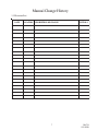
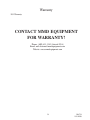
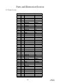
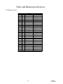
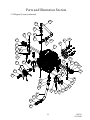
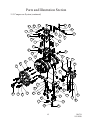
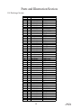
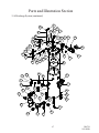
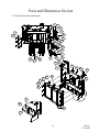
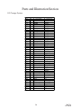
Service and
Maintenance
Manual
LR 450
Portable
Air Compressor
This manual must be read carefully before using your MMD Equipment Compressor.
Store in a safe and convenient location for future reference.
For technical support:
Phone: (800) 433-1382 (Outside USA)
Email: [email protected]
Website: www.mmdequipment.com
308754
11/1/2010
2
308754
11/1/2010
Contents
Manual Change History................................................................................................7
1.1 Revision List....................................................................................................7
Welcome........................................................................................................................8
2.1 General Information..........................................................................................8
2.2 Overview .........................................................................................................8
Safety...................................................................................................................9-14
3.1 General Safety Overview...................................................................................9
3.2 Safety Precautions..........................................................................................10
3.3 Safety and Information Decals..........................................................................12
Specifications..............................................................................................................15
4.1 Specification Sheet........................................................................................15
Description of Components..............................................................................16-21
5.1 Engine............................................................................................................16
5.2 Drive Coupling...............................................................................................16
5.3 Compressor Airend.......................................................................................16
5.4 Separator System..........................................................................................16
Separator Tank.........................................................................................16
Separator Element......................................................................................16
5.5 Pressure Relief Valve.....................................................................................16
5.6 Fuel Tanks......................................................................................................17
5.7 Engine Air Filter...............................................................................................17
5.8 Cooling Systems.............................................................................................17
Engine Radiator..........................................................................................17
Engine Charged Air Cooler..........................................................................17
Compressor Oil Cooler.............................................................................17
5.9 Compressor Inlet Valve...................................................................................17
5.10 Compressor Oil Filter....................................................................................17
5.11 Compressor Oil Thermal Valve......................................................................18
5.12 Minimum Pressure Valve...............................................................................18
5.13 Blowdown Valve..........................................................................................18
5.14 Manual Load/Unload Valve...........................................................................18
5.15 Discharge Pressure Regulator........................................................................18
5.16 Digital Control Panel................................................................................18
Engine Oil Pressure Parameter.................................................................18
Engine Coolant Temperature Parameter........................................................19
Compressor Discharge Temperature Parameter...........................................19
Compressor Discharge Pressure Parameter.................................................19
3
308754
11/1/2010
Contents
Description of Components (continued)............................................................16-20
5.16 Digital Control Panel (continued)...................................................................19
Hourmeter...................................................................................19
Tachometer....................................................................................19
Fuel Level.................................................................................................19
Battery.......................................................................................19
5.17 Gauges...............................................................................................19
5.18 Emergency Stop Button................................................................................19
5.19 A-Frame Drawbar and Hitch........................................................................20
5.20 Running Gear................................................................................................20
5.21 Safety Chains................................................................................................20
5.22 Breakaway Switch.........................................................................................20
Installation..........................................................................................................21-24
6.1 System Installation Overview...........................................................................21
6.2 Towing the Machine.......................................................................................21
6.3 Parking the Machine........................................................................................21
6.4 Placing the Machine........................................................................................22
6.5 Service Valves.......................................................................................22
6.6 Remote Drains......................................................................................22
6.7 Auxillary Fuel Tank...................................................................................22
6.8 Pre-Startup Inspection ...................................................................................23
6.9 Machine Documentation.................................................................................23
6.10 Check Fluid Levels.......................................................................................23
6.11 Initial Startup Preparation..............................................................................24
6.12 Initial Startup.................................................................................................24
Operation.............................................................................................................25-26
7.1 Routine Operating Procedures........................................................................25
Routine Startup Preparation........................................................................25
Routine Startup Procedure.........................................................................25
Routine Shutdown Procedure.....................................................................26
7.2 Emergency Stop Procedure............................................................................26
4
308754
11/1/2010
Contents
Maintenance........................................................................................................27-36
8.1 Maintenance Overview....................................................................................27
8.2 Maintenance Schedule...........................................................................27-28
8.3 Recommended Spare Parts List......................................................................28
8.4 Parts and Service Contact Information............................................................28
8.5 Maintenance Log............................................................................................29
8.6 Separator Element Replacement......................................................................30
8.7 Engine Air Filter Replacement..........................................................................31
8.8 Compressor Oil.....................................................................................32-34
Specifications.......................................................................................32
Adding Compressor Oil.............................................................................33
Changing Compressor Oil..................................................................33-34
8.9 Compressor Oil Cooler.................................................................................34
8.10 Compressor Oil Filter....................................................................................34
8.11 Engine Cooling System Maintenance..............................................................35
Engine Coolant...........................................................................................35
Engine Radiator..................................................................................35-36
Engine Fan.................................................................................................36
Engine V-Belt.............................................................................................36
8.12 Battery..........................................................................................................36
Troubleshooting...................................................................................................37-38
9.1 Troubleshooting Chart....................................................................................37
9.2 Parts and Service Contact Information............................................................38
Warranty.....................................................................................................................39
10.1 Warranty Policy............................................................................................39
Parts and Illustration Section...........................................................................40-61
11.1 Frame System...............................................................................................40
11.2 Engine System..............................................................................................42
11.3 Compressor System.....................................................................................44
11.4 Discharge System..........................................................................................46
11.5 Cooler System..............................................................................................48
11.6 Electical System..........................................................................................50
11.7 Exhaust System............................................................................................52
5
308754
11/1/2010
Contents
Parts and Illustration Section (continued)......................................................44-61
11.8 Air Filter System............................................................................................54
11.9 Canopy System............................................................................................56
11.10 Hose System...............................................................................................58
11.11 Engine Air/Oil Schematic.............................................................................59
11.12 Airend Air/Oil Schematic.............................................................................60
11.13 System Wiring Diagram...............................................................................61
6
308754
11/1/2010
Manual Change History
1.1 Revision List
DATE
LOCATION DESCRIPTION OF CHANGE
7
INITIALS
308754
11/1/2010
Welcome
2.1 General Information
Thank you for choosing the LR 450 Portable Compressor. Before
operating this system, read over this manual and become well acquainted with your new machine. Doing this will increase your safety
and maximize the life of the machine.
While this manual is written to be as accurate as possible, MMD
equipment strives to continually improve the efficiency and performance
of its machines. As a result, sometimes there may be slight differences
between a given version of the manual and the machine.
Service and
Maintenance
Manual
LR 450
Portable
Air Compressor
This manual must be read carefully before using your MMD Equipment Compressor.
Store in a safe and convenient location for future reference.
For technical support:
Phone: (800) 433-1382 (Outside USA)
Email: [email protected]
Website: www.mmdequipment.com
308754
11/1/2010
2.2 Overview
The LR 450 Portable Compressor is a strategically designed system. It integrates all major components
on a single, environmentally sealed frame, which is enclosed in a tough, weather-resistant canopy.
The LR 450’s rotary screw design guarantees continuous air output of up to 450 SCFM (standard
cubic feet per minute) at 100 PSI (pounds per square inch). With remote fluid drains and hinged doors,
virtually all components are accessible for maintenance and service. Instrumentation clearly displays
pressures, temperatures, RPM, and hours of
operation. Other features, including a spin-on
compressor oil filter and a drop-in separator
element, reduce the time and costs associated
with routine maintenance.
The LR 450 also has enhanced safety features to
protect your valuable resources: minimum
pressure valve, high compressor oil temperature
shutdown, high discharge pressure shutdown,
automatic blowdown device, pressure relief valve,
and clearly displayed warning/information decals.
8
308754
11/1/2010
Safety
3.1 General Safety Overview
Remember, safety is basically common sense. While there are standard safety rules, each situation has
its own peculiarities that cannot always be covered by rules. Therefore with your experience and
common sense, you are in a position to ensure the safety of yourself and others. Lack of attention to
safety can result in: accidents, personal injury, reduction in efficiency, and worst of all – Loss of Life.
Watch for safety hazards and correct them promptly.
Understanding the proper operation of this equipment is critical to its safe operation. The owner, lessor,
and/or operator of this equipment is hereby notified and forewarned that any failure to observe the
safety and operating guidelines may result in injury and/or damage. MMD Equipment expressly disclaims responsibility or liability for any injury or damage caused by failure to observe these specified
precautions or by failure to exercise the ordinary caution and due care required while operating or
handling this equipment, even though not expressly specified.
In addition to following these safety guidelines, the operator should follow any company specific guidelines and procedures. Consult your immediate supervisor for specific company safety guidelines and/or
procedures.
The following safety symbols are used throughout this manual to draw attention to important information.
If the information is not carefully read and the instructions are not followed, severe injury, death, and/or
damage to property and equipment may occur.
Indicate[s] an imminently hazardous situation, which, if
not avoided, will result in death or serious injury.
Indicate[s] a potentially hazardous situation, which, if not
avoided, could result in death or serious injury.
Indicate[s] a potentially hazardous situation, which, if not
avoided, could result in minor or moderate injury.
Indicate[s] a potentially unsafe situation or practice,
which, if not avoided, can result in property and/or
equipment damage only.
9
308754
11/1/2010
Safety
3.2 Safety Precautions
The following safety precautions are a general guide to safe operation of the equipment.
This is a pressurized system. Do not attempt to remove
any part of this machine without first completely relieving
entire system of pressure. Do not attempt to service any
part of the equipment while in operation. Never attempt
to repair or modify any pressure vessel or device.
System contains hot oil. The system must be shut off prior
to servicing. Then permit system to cool down prior to
adding compressor oil or servicing the unit.
Do not use air from this system for breathing or food
processing. Air from this system will cause severe injury
or death if used for breathing or food processing.
The system is designed to compress air. Do not attempt
to compress other gases. Compression of other gases
may create a situation where an explosion or fire may
occur.
Do not use flammable solvents for cleaning system components as this can cause the unit to ignite or explode
during operation. Keep combustibles out of and away
from system inlets and any associated enclosures.
Never disable, override, or remove safeties, either temporarily or permanently.
Do not modify systems to operate equipment at a higher
or lower pressure than specified.
10
308754
11/1/2010
Safety
3.2 Safety Precautions (continued)
Read and understand this manual and all other safety
instructions before using this equipment. Failure to follow
operating instructions and/or failure to follow maintenance
procedures and intervals could result in personal injury,
death, and/or damage to equipment and property.
Use only MMD Equipment approved replacement parts.
Never place machine on a grade more than 15 degrees.
Never operate the machine in an enclosed area.
Keep doors closed on the machine during operation.
Check engine’s operator manual for required service
and maintenance intervals.
Never tow trailer unless all electrical lights are
connected and working properly.
11
308754
11/1/2010
Safety
3.3 Safety and Information Decals
This machine is supplied with a full complement of safety and identification decals. These decals are
affixed to the unit during final assembly. These decals must be clearly visible and undamaged. Should
any of these decals become illegible or damaged, immediately replace the decal.
Hot Exhaust
Pressurized System
Fan Guard
Hot Pressurized Oil
Electrical Shock
Read Manual
Negative Ground System
Hot Coolant
12
308754
11/1/2010
Safety
3.3 Safety and Information Decals (continued)
Overfill
Towing
Compressor Oil
Do Not Lift
Pinch Point
Breathing Air
Connect Hose
13
308754
11/1/2010
Safety
3.3 Safety and Information Decals (continued)
Emergency Shutdown Procedure
Start-up/Shutdown Procedure
14
308754
11/1/2010
Specifications
4.1 Specification Sheet
Air De live ry @ 100 PSI
C FM
464
Engine Spe e d
RPM
2500
Engine
Isuzu 3.0L 4CYL Turbo
Diesel
Engine Fue l Spe cification
Low Sulfur Diesel
SCA20G with 1.20 Gear
Ratio
Compre s s or Aire nd
Compre s s or Oil Capacity
13 Gallons
Ele ctrical Sys te m
12 VDC
M achine We ight
5800 lbs (Wet)
Ove rall Dime ns ions
16 7 " L x 6 3 " H x 8 7 " W
Duty Cycle
Continuous Duty
M achine Ope rating Angle
15° maximum
Ambie nt Conditions
- 40°F to 115°F
*SPECIFICATIONS SUBJECT TO CHANGE WITHOUT PRIOR NOTICE*
103.00
86.66
66.90
63.00
69.35
74.00
39.25
16.50
42.00
72.76
137.87
166.12
167.12
15
308754
11/1/2010
Description of Components
5.1Engine
The LR 450 contains an Isuzu 4 cylinder diesel engine. This engine has been specially modified to
handle the rugged duty required for its operation. This engine is setup to run on low sulfur diesel fuel.
The engine speed is regulated electronically by the machine controller.
5.2Drive Coupling
Power from the engine is transmitted to the compressor input shaft through a specially designed drive
coupling. The drive coupling consists of a highly torsionally flexible rubber disc that mates with an
engine flywheel flange. The coupling provides a torque limitation to protect from system overloads.
5.3 Compressor Airend
The LR 450 airend is a positive displacement, oil flooded, rotary screw type unit employing one stage of
compression to achieve the desired pressure. Components include a housing (stator), two screws
(rotors), bearings, and bearing supports. Power from the engine flywheel is transferred through a gear
set to the male rotor. The female rotor is driven by the male rotor. There are five lobes on the male
rotor while the female rotor has six roots. In operation, two helical grooved rotors mesh to compress
air. Inlet air is trapped as the male lobes roll down the female grooves, pushing trapped air along,
compressing it until it reaches the discharge port at the end of the stator and delivers smooth-flowing,
pulse-free air. Being an oil flooded system, the oil serves three purposes: lubricates the rotating parts
and bearings, serves as a cooling agent for the compressed air, and seals the running clearances.
5.4 Separator System
I. Separator Tank
From the compressor airend, the compressed air and hot oil flow into a steel, ASME coded,
pressure vessel, rated at 250 PSI, that acts as an oil reservoir. This tank is the first of two stages in
separating the oil and compressed gas mixture. From the bottom of the separator tank, oil is forced
to the oil filter.
II. Separator Element
At the top of the separator tank is the separator element. The separator element removes the oil
mist from the air as it is passed on to the minimum pressure valve. As the air/oil mist passes through
the outside of the media, oil gathers on the interior walls and settles to the bottom of the element.
Collected oil is returned to the compressor airend through the oil return line. The separator will filter
the oil concentration in the air to less than 3 parts per million.
5.5 Pressure Relief Valve
I. Separator Tank Relief Valve
This valve vents separator tank pressure to atmosphere should the pressure inside the tank exceed
175 PSI.
16
308754
11/1/2010
Description of Components
5.6 Fuel Tanks
The LR 450 fuel system consists of two 24 gallon fuel tanks. The primary fuel tank is located on the
curb side of the machine. The auxiliary fuel tank is located on the road side of the machine. The fuel
tanks are joined together to function as one 48 gallon fuel tank. Both tanks can be filled from either fuel
tank. Use only low sulfur diesel when fueling this machine.
5.7Engine Air Filter
The engine air filter is a two stage, dry type intake filter with a gravity evacuator and replaceable internal
element. On the outlet of the engine air filter is an air filter restriction indicator. This indicator serves as
a maintenance tool. A “check filters” warning will display on the control panel when the filter need to be
serviced.
5.8 Cooling Systems
I. Engine Radiator
The radiator is designed to dissipate the heat load of the engine and is mounted in front of the
specially selected engine fan. Hot engine coolant is passed through the interior of the radiator and
heat is transferred to the air that passes across the cooling fins.
II. Engine Charged Air Cooler
The charged air cooler is designed to cool the engine intake air after it passes through a turbocharger but before the air enters the engine. Cooling the air before entering the engine will optimise
the power for the combustion process.
III. Compressor Oil Cooler
The compressor oil cooler is designed to dissipate the heat created during the compression of air.
The oil cooler is mounted adjacent to the engine radiator. This works similar to the engine radiator
but is designed to withstand the full compressor system working pressure.
5.9 Compressor Inlet Valve
The compressor inlet valve is a normally open air intake valve bolted to the compressor airend. When
the system is shut down, this valve also acts as a check valve that prevents the air/oil mixture within the
compressor airend from entering the inlet tubing.
5.10 Compressor Oil Filter
The compressor oil filter is a full flow, spin-on canister. It has been specially designed to handle the full
system pressure. The oil filter is mounted downstream of the separator tank to ensure all contaminants
are prevented from being passed on to the compressor oil cooler. An oil filter restriction indicator is
located on the oil filter head. This indicator serves as a maintenance tool. A “check filters” warning will
display on the control panel when the filter needs to be serviced.
17
308754
11/1/2010
Description of Components
5.11 Compressor Oil Thermal Valve
The compressor oil thermal valve is a thermostatically controlled bypass valve that allows varying
amounts of oil, depending upon the temperature, to bypass the oil cooler. The oil thermal valve directs
oil flow back to the compressor airend until the system reaches 180°F. Once at system operating
temperature, the valve shifts directing the flow through the oil cooler before returning to the compressor
airend.
5.12 Minimum Pressure Valve
To ensure there is adequate pressure to produce proper oil flow throughout the system, a spring loaded,
normally closed minimum pressure valve is set to maintain at least 50 PSI in the separator tank.
5.13 Blowdown Valve
The blowdown valve is a shuttle valve that vents system pressure to atmosphere when the system is shut
down. This is done to prevent the high torque load that would be required to overcome the static
pressure. The blowdown valve is stamped with an “I” and a “P”. The “I” side is connected to dry air
from the separator tank, and the “P” side is the pilot signal coming from the compressor inlet valve.
5.14 Manual Load/Unload Valve
This turn valve is used to limit the compressor system pressure. When the valve is in the closed position, the system will build to the regulator setting. If the valve is in the open position, the system will
build to approximately 45 PSI.
5.15 Discharge Pressure Regulator Valve
This valve, located downstream of the separator element, is used to set the desired discharge pressure.
This valve will send a pneumatic signal to the inlet valve to start closing when the pressure exceeds the
set-point. This signal will also adjust the speed of the engine. This system has a maximum operating
pressure of 100 PSI and a standby pressure of 130 PSI.
5.16 Digital Control Panel
The LR 450 incorporates a digital control panel that monitors and records numerous parameters.
I. Engine Oil Pressure Parameter
This feature displays the oil pressure inside the engine block. When the pressure drops below 20
PSI, a warning will display on the control panel. The system will shut down when the engine oil
pressure drops below 15 PSI.
18
308754
11/1/2010
Description of Components
5.16 Digital Control Panel (continued)
II. Engine Coolant Temperature Parameter
This feature displays the temperature of the engine coolant. If the temperature reaches 200°F, a
warning will display on the control panel. The system will shut down if the temperature reaches
2200F.
III. Compressor Discharge Pressure Parameter
This feature displays a failure if the system pressure of the air compressor exceeds 150 PSI. If the
pressure reaches 150 PSI, the system will shut down.
IV. Compressor Discharge Temperature Parameter
This feature displays a failure if the compressor discharge temperature exceeds 240°F. If the
temperature reaches 240°F, the system will shut down.
VI. Hourmeter
The hourmeter records the total number of operating hours. It serves as a guide in following the
recommended maintenance schedule. The hourmeter will only run when the engine is operating.
VII. Tachometer
This feature displays the speed of the engine. If the speed of the engine reaches 2600 RPM or
drops below 1400 RPM, a warning will display on the controller. If the speed of the engine reaches
2700 RPM or drops below 1300 RPM, the system will shut down.
VIII. Fuel Level
This feature displays the percentage of fuel in the fuel tanks. When the fuel level is at 15%, a
warning will display on the control panel. The system will shut down when the fuel level is at 0%.
IX. Battery
This feature displays the voltage level of the battery. If the voltage is at 11.5 volts, a warning will
display on the control panel. The system will shut down if the voltage reaches 7.6 volts.
5.17 Gauges
The LR 450 is also equipped with two analog gauges. A compressor discharge pressure gauge and fuel
level gauge.
5.18 Emergency Stop Button
In the case of a dangerous situation, the LR 450 is equipped with an emergency stop button. The
emergency stop button is to only be used when imminent danger is present. Using the emergency stop
button for standard shutdown WILL cause excessive wear on the drive coupling of the system. Damage
to the drive coupling due to improper shut down WILL void the warranty for the drive coupling.
19
308754
11/1/2010
Description of Components
5.19 A-Frame Drawbar and Hitch
The A-frame drawbar and hitch connects the towing vehicle and the machine. This drawbar has been
designed to handle the rugged duty required for its operation.
5.20 Running Gear
Axle, wheel, and tires are all sized for their job. This machine is equipped with a single axle. The design
of the machine, plus the axle design, makes towing at highway speed possible.
5.21 Safety Chains
Safety chains should be attached on opposite sides of the machine’s drawbar and crossed under the
drawbar when passed forward to the towing vehicle so as to cradle the drawbar in the event of a
breakaway. Slack should be sufficient to permit full turns.
5.22 Breakaway Switch
The cable for the breakaway switch should be attached to the towing hitch of the vehicle being used to
tow the compressor. In the event of a breakaway the trailer breaks will engage, stopping the trailer
immediately.
20
308754
11/1/2010
Installation
6.1 System Installation Overview
The LR 450 should be installed only by those who have been delegated to do so, trained, and who have
read and understand this manual. Failure to follow the instructions, procedures, and safety precautions
in this manual may result in accidents and injuries.
Install, use, and operate this system only in full compliance with all pertinent O.S.H.A., Federal, State,
and Local codes or requirements, in addition to MMD Equipment and any company’s regulations.
Do not modify this system except with written factory approval.
6.2 Towing The Machine
I.
Carefully inspect the machine’s ball hitch, drawbar, and chains look for excessive wear, corrosion,
cracked, bent, dented, or otherwise deformed or degraded member, loose nuts, bolts, or other
fasteners. Do the same on the towing vehicle’s hitch and related hardware. If inspection shows
any worn or damaged parts, DO NOT TOW the machine until repairs are made.
Torque Specifications:
Hitch fasteners: 150 ft-lbs.
Wheel lug fasteners: 90 - 120 ft-lbs.
Safety chain fasteners: 50 ft-lbs.
II.
Chock or block the machine’s wheels and raise the drawbar to the approximate level of the
towing vehicle hitch.
III. Engage, close, and lock the coupling device.
IV. Attach safety chains.
V. Attach electrical connection.
VI. Attach breakaway switch.
VII. Fully retract front screw jack. Place any retractable stand in a full up and locked position with the
stand horizontal.
VIII. Carefully inspect the tires and check the tire pressure.
IX. Test all running, tail, stop, and directional lights. Make sure that all lights and reflecting surfaces
are clean and in good condition.
X. Close and latch the doors and access panels.
XI. Set the parking brake in the towing vehicle. Only then remove chocks or blocks from machine
wheels.
6.3 Parking The Machine
I.
II.
III.
IV.
V.
Chock or block the wheels.
Disconnect the electrical connection.
Disconnect the safety chains and wrap them around the drawbar.
Lower front jack to raise machine off the towing vehicle’s hitch.
Move the towing vehicle clear of the machine.
21
308754
11/1/2010
Installation
6.4 Placing The Machine
The first step to installing the LR 450 is parking the system on a solid, level surface. This machine is
designed to run at a 15° grade maximum. If you must park on any grade, park across the grade so that
the machine does not tend to roll. The machine must be supplied ample ambient air, as the system will
overheat if the cooling air intake’s temperature exceeds ambient conditions.
3/4" SERVICE
VALVE
2" SERVICE
VALVE
RADIATOR DRAIN
ENVIROMENTAL
PAN DRAIN
COMPRESSOR
OIL DRAIN
3/4" SERVICE
VALVE
FUEL DRAIN
ENGINE OIL
DRAIN
3/8" NPT AUXILLARY FUEL
TANK FUEL RETURN LINE
3/8" NPT AUXILLARY FUEL
TANK FUEL FEED LINE
6.5 Service Valves
The LR 450 is equipped with four service valves. A 2” NPT service valve and two 3/4” NPT service
valves are located in the rear of the machine underneath the control panel. Located in the front of the
machine is a remote 3/4” NPT service valve.
6.6 Remote Drain Ports
The engine oil, radiator, compressor oil, fuel, and environmental pan drains are all located behind the
curbside tire underneath the machine. Remove the 3/4” NPT plugs, 1/4” for the radiator, to drain the
fluids from the machine. The engine oil and the compressor oil drains utilize a ball valve to control the oil
flow. These valves are located next to the battery on the curb side of the machine.
6.7 Auxillary Fuel Tank
Use the two 3/8” NPT ports located in front of the curbside tire, underneath the machine, to connect an
auxiliary fuel tank. Connect the fuel return line to the port closest to the tire. Connect the fuel feed line
to the remaining port.
22
308754
11/1/2010
Installation
6.8 Pre-Startup Inspection
This inspection must be done prior to initial system startup.
I. Check all assemblies, clamps, fittings, hose connections, nuts, and bolts to ensure they are properly
tied and secured.
II. Remove all tools, rags, and installation equipment from the area.
III. Check all valves to ensure they are in the correct operating position.
A. Engine Oil Drain Valve = Closed
B. Compressor Oil Drain Valve = Closed
C. Manual Cold Start Valve = Closed
6.9 Machine Documentation
Record serial numbers for main components in the system.
I. Machine Serial Number
__________________________________________
II. Compressor Airend Serial Number
__________________________________________
III. Engine Serial Number
__________________________________________
IV. Separator Tank Serial Number
__________________________________________
V. Digital Control Panel Serial Number
__________________________________________
6.10 Check Fluid Levels
The machine is factory filled prior to shipment. The proper fluid levels are also listed in the maintenance
section.
I.
II.
III.
IV.
Separator Tank Oil Level = Halfway on the separator tank sightglass.
Engine Radiator Coolant Level = Bottom of the radiator fill neck.
Engine Coolant Recovery Bottle = Fill to the cold line.
Engine Oil Level = Full on the dipstick.
23
308754
11/1/2010
Installation
6.11 Initial Start-up Preparation
I. Reconnect battery terminals. Ensure the red cable is connected to the battery’s positive terminal,
and the black cable is connected to the battery’s negative terminal.
II. Verify fluid levels and refill if necessary.
III. Verify all electrical connections are secure.
IV. Check all hose connections for leaks.
V. Close all service valves.
6.12 Initial Startup
At this point the system is ready to test for functionality. Be sure to complete all of the previous steps
prior to continuing.
I.
II.
III.
IV.
V.
VI.
VII.
VIII.
IX.
X.
Press the “AUTO” button on the controller.
Check the controller for warnings or error codes.
Press the “RUN” button on the controller to begin the startup sequence. The machine will cycle
through a preheat, cranking, and warm-up period. This will last approximately three minutes.
After the warm-up period is complete the compressor will switch to high speed of 2500 RPM for
approximately 30 seconds then will return to a low speed of 1800 RPM.
Check system for leaks.
Allow system to run until engine coolant temperature reaches 190°F.
Check for leaks again.
Open service valves to verify engine speed increases to 2500 RPM.
Close service valves.
Press the “OFF” button on the control panel. The control panel will ask to start the cooldown
sequence.
Press the “ENTER” button on the control panel. This will start the cooldown sequence. The
cooldown sequence will last approximately three minutes.
DO NOT press the “OFF” button two times
consecutively or during the cooldown sequence.
This will bypass the cooldown sequence.
Bypassing the cooldown sequence will cause
excessive wear on the drive coupling. Damage to
the drive coupling due to improper shut down
WILL void the drive coupling warranty.
XI. Verify all fluid levels and refill if necessary.
XII. Initial Startup testing is complete.
24
308754
11/1/2010
Operation
7.1 Routine Operating Procedures
The LR 450 should only be operated by those who have been delegated to do so, trained, and who
have read and understand this manual. Failure to follow the instructions, procedures, and safety
precautions in this manual may result in accidents and injuries.
Operate this system only in full compliance with all pertinent O.S.H.A., Federal, State, and Local codes
or requirements, in addition to MMD Equipment and any company’s regulations.
The LR 450 utilizes a specially designed system controller that electronically controls all aspects of the
compressor’s operation. Follow the instructions carefully. Improper use of the control panel will cause
damage to the drive coupling. Damage to the drive coupling due to improper use will void the warranty.
I. Routine Start-up Preparation
A.
B.
C.
D.
E.
F.
Verify service valves are closed.
Verify fluid levels and refill if necessary.
Check battery cable connections for corrosion.
Check the condition of the engine fan belt.
Check for fuel, oil, and/or coolant leaks.
Press the “AUTO” button on the control panel and check for warnings or error codes.
II. Routine Start-up Procedure
A. Press the “RUN” button on the control panel to begin the start up sequence.
The machine will cycle through a preheat, cranking, and
warm-up period. This will last approximately three
minutes. Machine is ready for use when the system
pressure reaches 100 PSI.
B. Open the service valves to begin using air.
25
308754
11/1/2010
Operation
7.1 Routine Operating Procedures (continued)
III. Routine Shutdown Procedure
A. Close all service valves.
B. Press the “OFF” button on the control panel. The control panel will display “COOLDOWN?”
as a question to start the cooldown sequence.
C. Press the “ENTER” button on the control panel to start the cooldown sequence. The engine will
run through a cooldown sequence that will last approximately three minutes.
The purpose of the cooldown sequence is to properly decrease system pressure before shutdown.
To protect the drive coupling from damage, the system pressure must be below 50 PSI before the
machine shuts down.
DO NOT press the “OFF” button two times
consecutively or during the cooldown sequence.
This will bypass the cooldown sequence.
Bypassing the cooldown sequence will cause
excessive wear on the drive coupling. Damage to
the drive coupling due to improper shut down
WILL void the drive coupling warranty.
7.2 Emergency Stop Procedure
In the event of an emergency and the LR 450 must be stopped suddenly, the machine is equipped with
an Emergency Stop switch. This should only be used in the case of an emergency. This should not be
used as a routine shutdown device. Using the emergency stop button for standard shutdown WILL
cause excessive wear on the drive coupling. Damage to the drive coupling due to improper shutdown
will void the drive coupling warranty. If the emergency stop button must be used, do not operate this
machine until the problem has been resolved.
I. Emergency Shutdown Procedure
A. Press the Emergency Stop button on the control panel.
B. Reset Emergency Stop button.
C. Correct source of emergency situation prior to operating this machine again.
26
308754
11/1/2010
Maintenance
8.1 Maintenance Overview
This section contains instructions for performing the inspection, lubrication, and maintenance procedures
required to ensure the system is in proper operating condition. The importance of performing the
maintenance described herein cannot be over emphasized. A planned program of periodic inspection
and maintenance will help avoid premature failure and costly repairs. Keep an accurate logbook for
maintenance, service, and operating hours. The maintenance schedule intervals on this system are
maximum intervals. The factory recommended maintenance schedule is based on favorable operating
conditions. For continuous duty, extreme temperature, etc., service more frequently. Neglecting routine
maintenance can result in machine failure or permanent damage.
This system should be maintained only by those who have been delegated to do so, trained, and who
have read and understand this manual. Failure to follow the instructions, procedures, and safety
precautions in this manual may result in accidents and injuries.
8.2 Maintenance Schedule
INTERVAL
DESCRIPTION
1. Check separator tank oil level.
2. Check engine coolant level in coolant bottle.
EVERY 10 HOURS OR
DAILY
3. Check control panel for filter warnings
4. Check for fuel, oil, air, and coolant leaks.
5. Check battery hold down for security.
1. Drain liquid from separator tank. More frequent draining
may be required under high humidity conditions.
2. Inspect lifting frame.
EVERY 50 HOURS OR
WEEKLY
3. Check drawbar and two hitch bolts torque (and prior to
each move). 70 ft- lbs
4. Check tire pressure. 65 PSI Maximum
5. Check wheel nut torque (and prior to each move). 95 ftlbs
1. Change compressor oil and oil filter element.
EVERY 500 HOURS OR 6 2. Clean battery terminals.
MONTHS
3. Check battery hold- down and cables for wear.
4. Check engine air filter connections, fittings, and clamps.
27
308754
11/1/2010
Maintenance
8.2 Maintenance Schedule (continued)
INTERVAL
DESCRIPTION
EVERY 500 HOURS OR 6 5. Check radiator hoses and clamps.
MONTHS
6. Check integrity of engine mounts.
1. Install new air filter element.
2. Check all door gaskets, hinges, and latches.
EVERY 1000 HOURS OR
1 YEAR
3. Clean and flush engine cooling system.
4. Check Emergency Stop button functionality.
5. Check separator tank pressure relief valve.
6. Clean cooler fins on all coolers.
Compressor oil and oil filter is to be changed after the first 50
hours of operation. After this, normal intervals are to be
followed.
Check engine’s operator manual for required service and
maintenance intervals.
8.3 Recommended Spare Parts List
PART NUM BER
DESCRIPTION
3 03 3 8 6
Compressor Oil Filter
308585
Separator Element
308806
Engine Oil Filter
308807
Engine Air Filter Element
308759
SCA20G Shaft Seal Repair Kit
8.4 Parts and Service Contact Information
Phone: (800) 433-1382 (Outside USA)
Email: [email protected]
Website: http://www.mmdequipment.com
28
308754
11/1/2010
Maintenance
8.5 Maintenance Log
Accum.
Hours
Date
Service Performed
Parts Replaced
29
Service Work By
308754
11/1/2010
Maintenance
8.6 Separator Element Replacement
When the oil vapor in the discharge air becomes excessive, the separator element may need replacing.
This should not be necessary more than once a year under normal operating conditions.
I.
Replacement Procedure
A. Shut down machine and allow to cool for approximately 10 minutes.
B. Verify entire system pressure is relieved before proceeding.
When disconnecting hoses, be sure to note the location to
ensure there is no confusion when reconnecting.
C.
D.
E.
F.
Disconnect the 2” hose from the minimum pressure valve.
Disconnect the 5/16” tubes from the regulator valve.
Disconnect the 1/8” tube from the blowdown valve.
Disconnect the 1/4” tube from the oil return line.
Note the location of the separator tank lid so that it can
be reinstalled in the same orientation.
G. Remove the ten 5/8” bolts holding the separator tank lid in place.
The separator tank lid has a pickup tube installed and
damaging or moving the tube will affect the machines
functionality.
H. Lift and remove the lid from the package.
I. Remove the separator element.
Substitute filters may have inadequate working pressure
limits, resulting in filter leakage or rupture. Replacement
filters must be the same quality and type as the original
separator element.
The separator element flange must have a gasket on each side
to seal the lid on one side and the vessel on the other. The
staple in each gasket acts as a static ground and must not be
removed.
J.
K.
L.
M.
N.
O.
Install a new element.
Reinstall the separator tank lid.
Reinstall the ten 5/8” bolts.
Uniformly tighten the bolts in a crisscross pattern to a torque of 220ft-lb.
Reconnect all hoses and ensure they are correctly located and tightened properly.
Start machine and check for any leaks.
30
308754
11/1/2010
Maintenance
8.7 Engine Air Filter Replacement
I.
Loosen the clamps that secure the engine air filter’s rear cover to the filter housing.
II. Remove and clean the rear cover.
III. Remove the air filter element.
IV. Clean the canister with a damp cloth inside and out. DO NOT blow dirt out with compressed air.
Never blow dirt out of the interior of the filter housing. This
may introduce dust downstream of the filter. Instead, use a
clean damp cloth.
V. Prior to cleaning an element, check the element for damage. Damaged air filter elements must be
replaced.
A. Place a bright light inside the element to inspect for damages or leaks.
B. Inspect all seals and seal contact surfaces on the housing. Should faulty seals be evident, correct
the condition immediately.
VI. If element is undamaged, clean the air filter element.
A. The maximum number of times that an element should be cleaned is 2 times; however, the
element should be used no longer than a period of 1 year without changing.
Do not strike the element against any hard surfaces for cleaning as it may possibly rupture the element. Do not oil element.
B. When cleaning the element with compressed air, never let the air pressure exceed 30 PSI.
Reverse flush the element by directing the compressed air up and down the pleats in the filter
media from the inside of the element. Continue reverse flushing until all dust is removed. Should
any oil or greasy dirt remain on the filter surface, the element should be replaced.
When cleaning an element, the element will be damaged if you
exceed the recommended maximum air pressure of 30 PSI.
C. If the cleaned element is to be stored for later use, it must be stored in a clean container.
VII. Install the air filter element.
VIII. Install the rear cover and tighten clamps. Install with rubber evacuator cup down.
IX.
Verify the control panel does not show a filter warning.
31
308754
11/1/2010
Maintenance
8.8 Compressor Oil
It is important that the compressor oil be of a recommended
type, and inspected and replaced as stated in this manual.
The combination of a separator element loaded with dirt
and oxidized oil products together with increased air velocity as a result of this clogged condition may produce a
critical point while the machine is in operation where ignition can take place and could cause a fire in the separator
tank.
The following are general characteristics for a rotary screw lubricant. Due to the impossibility of establishing
limits on all physical and chemical properties of lubricants which can affect their performance in the
compressor over a broad range of environmental influences, the responsibility for recommending and
consistently furnishing a suitable heavy duty lubricant must rest with the individual supplier if they choose not
to use the recommended MMD Equipment. rotary screw lubricant. The lubricant supplier’s
recommendation must, therefore, be based upon not only the following general characteristics, but also upon
his own knowledge of the suitability of the recommended lubricant in helical screw type air compressors
operating in the particular environment involved.
Mixing different types or brands of lubricants is not recommended due to the possibility of a dilution of the additives
or a reaction between additives of different types.
MMD Equipment Recommended Compressor Lubricant: DEXRON® III ATF
I.
Specifications
1. Flash point 400°F minimum.
2. Pour point -40°F.
3. Contains rust and corrosion inhibitors.
4. Contains foam suppressors.
5. Contains oxidation stabilizer.
Due to environmental factors, the useful life of all “extended life” lubricants may be shorter than quoted by the
lubricant supplier. MMD Equipment encourages the user
to closely monitor the lubricant condition and to participate
in an oil analysis program with the supplier.
No lubricant, however good and/or expensive, can replace
proper maintenance and attention. Select and use it wisely.
32
308754
11/1/2010
Maintenance
8.8 Compressor Oil (continued)
II. Adding Compressor Oil
A. Verify the machine is level to assure oil level in sightglass will be accurate.
B. Remove any dirt around the separator tank fill cap to prevent contamination from entering the
system.
Do not remove caps, plugs, or other components when the
system is running or pressurized. Stop system and relieve
all internal pressure before doing so. Failure to comply
with this warning will cause damage to property and serious
bodily harm.
C. Remove the separator tank fill cap.
D. Inspect and clean the fill cap. Replace if necessary.
E. Dexron III ATF can then be added until the oil level reaches halfway in the sightglass. Do not
over fill the separator tank. This will cause oil carryover in the discharge line and at blowdown.
Do not replace fill cap with a pipe cap; serious injury or damage could result. Replacement filters must be the same
quality and type as the original MMD Equipment fill cap.
F. Replace fill cap and tighten immediately.
III. Changing Compressor Oil
Initially the compressor oil and oil filter should be replaced after the first 50 hours of operation then
every 500 hours or 6 months. If the oil appears dirty or has a foul smell, it should be replaced
immediately.
A. Verify the machine is level to assure oil level sightglass will be accurate.
B. Remove any dirt around the separator tank fill cap to prevent contamination from entering the
system.
Do not remove caps, plugs, or other components when the
system is running or pressurized. Stop system and relieve all
internal pressure before doing so. Failure to comply with this
warning will cause damage to property and serious bodily
harm.
C.
D.
E.
F.
Remove the separator tank fill cap.
Inspect and clean the fill cap. Replace if necessary.
Drain oil from the bottom of the separator tank.
If compressor oil filter change is required, proceed to section 8.10, “Compressor Oil Filter”.
33
308754
11/1/2010
Maintenance
8.8 Compressor Oil (continued)
III. Changing Compressor Oil (continued)
G. Dexron III ATF can now be added until the oil level reaches halfway in the sightglass. Do not
over fill the separator tank. This will cause oil carryover in the discharge line and at blowdown.
Do not replace fill cap with a pipe cap; serious injury or damage could result. Replacement filters must be the same
quality and type as the original MMD Equipment fill cap.
H. Replace fill cap and tighten immediately.
I. Run system briefly to see if more oil needs to be added and to ensure there are no leaks.
8.9 Compressor Oil Cooler
Any sign of leakage from the compressor oil cooler justifies a pressure test to assure its integrity.
Cooler leaks should only be repaired by qualified service technicians. Dirt that clogs the cooling fins of
the cooler should be removed. The use of an air stream or high-pressure steam cleaner should be done
with caution so as to not damage the delicate fins. Bent cooling fins will reduce the cooling capability of
the compressor oil cooler.
8.10 Compressor Oil Filter
Initially the filter should be replaced after the first 50 hours of operation, then every 500 hours or 6
months. A dirty filter can restrict oil flow, causing high oil temperature, which will result in a system
shutdown.
I.
Compressor Oil Filter Replacement
A. Verify the compressor oil system is drained.
B. Using a strap wrench, remove the oil filter and o-ring.
C. Clean o-ring seating surface on the oil filter head.
Substitute filters may have inadequate working pressure
limits, resulting in filter leakage or rupture. Replacement
filters must be the same quality and type as the original oil
filter.
D. Apply a light film of oil to the new o-ring.
E. Hand tighten new filter until o-ring is seated in o-ring groove.
Mechanical overtightening may distort the threads or damage
the filter element seal.
F. Continue tightening filter by hand an additional 1/2 to 3/4 turn.
G. Continue with Changing the Compressor Oil steps.
34
308754
11/1/2010
Maintenance
8.11 Engine Cooling System Maintenance
The LR 450’s engine has a pressurized cooling system that contains a 50/50 mixture of water and
ethylene glycol. Maintenance of the system includes the engine coolant, belt tension, fan integrity, and
radiator. Further cooling system maintenance is defined in the engine manual.
I.
Engine Coolant
A. Specifications
This diesel engine requires a balanced coolant mixture of water and ethylene glycol base
antifreeze. This protects the engine cooling system from corrosion as well as freezing damage.
The LR 450 is shipped from the factory with a 50/50 mixture of water and ethylene glycol. In
tropical climates where freeze protection is not required, glycol engine coolant should still be
used to help prevent corrosion and pitting of cylinder liners.
B. Mixtures
Antifreeze concentration level should not exceed recommended levels. To do so can cause
cooling system failure.
1. A mixture of 50% antifreeze and 50% water is required for temperatures above -34° F.
2. A mixture of 60% antifreeze and 40% water is required for temperatures below -34° F.
This provides protection to -65° F.
3. Never exceed a 60% overall antifreeze mix.
C. Coolant Level
Before each start-up, when radiator is cold, the coolant level should be checked. When
needed, refill with a 50/50 solution of water and ethylene glycol, DO NOT use 100% antifreeze. The proper level for coolant in the system is to the bottom of the radiator fill neck and to
the cold line of the recovery bottle.
Check the coolant level only when the engine is stopped and
the temperature is below 160° F. Failure to do so can cause
personal injury from heated coolant spray.
II. Engine Radiator
A. Radiator Core
Any sign of leakage from the engine radiator may justify a pressure test to assure its integrity.
Radiator leaks should only be repaired by qualified service technicians. Dirt that clogs the
cooling fins of the radiator should be removed. The use of an air stream or high-pressure steam
cleaner should be done with caution so as to not damage the delicate fins. Bent cooling fins will
reduce the cooling capability of the radiator.
35
308754
11/1/2010
Maintenance
8.11 Engine Cooling System Maintenance (continued)
II. Engine Radiator (continued)
B. Radiator Pressure Cap
If coolant continually spills from radiator through the overflow, the radiator cap should be tested
and/or replaced with a 13 PSI rated cap. Be sure cap is tightened to the proper secure position.
III. Engine Fan
Check the engine fan for cracks, loose bolts, and bent or damaged blades. Replace damaged fans
immediately. Do not run system if any of the conditions exist. Make sure the hex head bolts
mounting the fan to the water pump pulley are properly torqued to 29 ft-lbs.
Never use the fan to rotate the engine. The blade(s) can be
damaged causing a fan failure, which can result in personal
injury or property damage.
IV. Engine V-Belt
Visually inspect the engine v-belt. Replace belt if cracked or frayed. Check engine manual for
proper belt tension.
8.12 Battery
The battery supplied with the LR 450 has been selected to have ample cold cranking amperes for quick
starts in cold weather. Keep the battery fully charged and if replacement is necessary the new battery
must be of equal or greater capacity.
Battery gas can explode causing acid burn to skin and blindness. Do not overcharge or jump the battery incorrectly.
36
308754
11/1/2010
Troubleshooting
9.1 Troubleshooting Chart
Problem
Cause
No fuel, low fuel, or contaminated
Unexpected
fuel
Shutdown
Safety shutdown occurred
Unable to obtain Improper engine timing
proper engine speed Clogged engine air filter
Damaged or loose motor mount
Excessive Vibration Low engine speed
Bent fan blade
Blowdown valve open
Machine will not
build up pressure
Insufficient air
delivery
Faulty drive coupling
Compressor undersized for air
requirement
Low engine speed
Blowdown valve open
Check fuel supply
Check control panel for cause
Adjust engine timing
Clean or replace immediately
Repair or replace
Verify engine speed minimum of 1800 RPM
Repair or replace immediately
Check pressure relief valve for leaks; replace as
needed
Replace coupling
Verify maximum air requirement
Check engine speed/adjust if necessary
Clean or replace immediately
Check all air lines, fittings, and connections for
leaks; repair as necessary
Repair or replace immediately
Repair or replace coupling
Drain oil to proper level
Check all piping lines and connections; repair as
necessary
Check return line depth and connections; repair
as necessary
Replace element
Leaks in air system
Faulty inlet valve
Faulty drive coupling
Separator tank overfilled
Excessive
compressor oil
consumption
Remedy
Leak in compressor oil system
Oil return line not removing oil
from separator element
Separator element damaged
37
308754
11/1/2010
Troubleshooting
9.1 Troubleshooting Chart (continued)
Problem
Compressor
overheating
Engine
overheating
Cause
Unit operating in area with limited
fresh air
Fan belts are loose or broken
Dirt build-up on oil cooler fins
Compressor oil level low
Compressor oil filter dirty
Thermal valve malfunctioning
Restriction in compressor oil lines
Oil cooler internally restricted
Unit operating in area with limited
fresh air
Fan belts are loose or broken
Dirt build-up on radiator fins
Thermostat not opening
Radiator internally restricted
Faulty or incorrect radiator cap
Faulty water pump
Coolant level low
Remedy
Reposition unit or open up confinement
Tighten or replace
Clean oil cooler thoroughly; be careful not to
damage fins
Check and fill to proper level
Replace filter
Repair or replace valve
Clean or replace lines
Clean internal tubes of cooler
Reposition unit or open up confinement
Tighten or replace
Clean radiator thoroughly; be careful not to
damage fins
Replace thermostat
Clean and flush radiator
Check cap/replace as required
Repair or replace pump
Add coolant to proper level
9.2 Parts and Service Contact Information
Phone: (800) 433-1382 (Outside USA)
Email: nick.luciano@mmd equipment.com
Website: http://www.mmdequipment.com
When calling for technical support, please have machine
serial number and this manual available.
38
308754
11/1/2010
WARRANTY
Warranty
10.1 Warranty
CONTACT MMD EQUIPMENT
FOR WARRANTY!
Phone: (800) 433-1382 (Outside USA)
Email: [email protected]
Website: www.mmdequipment.com
39
308754
11/1/2010
Parts and Illustration Section
11.1 Frame System
ITEM
QTY
1
2
3
4
5
6
7
8
9
10
11
12
13
14
15
16
17
18
19
20
21
22
23
24
25
26
27
28
29
30
31
32
33
34
35
36
37
38
39
40
41
42
43
44
45
46
47
48
49
50
51
52
53
6
1
1
1
4
8
10
10
1
2
1
1
4
2
1
2
8
16
8
2
6
2
2
1
1
2
1
2
1
2
2
2
1
4
2
1
4
4
4
2
2
2
1
2
2
2
2
2
1
1
2
1
1
Parts List
PART NUMBER
302764
308577
120-66020
308731
120-36992
929104-100
938004-062
938604-071
120-14966
120-26804
308579
960212-075
900000-030
970312-075
960204-025
308592
937806-094
938206-071
929806-100
902915-015
970306-038
307179
302382-MOD
960412-075
960612-075
974812-075
900000-010
929104-075
308595
925305-283
929806-600
970712-075
80216
925506-198
929806-450
308597
938210-112
937810-156
929810-150
900000-015
304643
301922-075
308630
960012-075
989712-075
938605-071
938005-078
929105-100
308637
308638
929705-075
922112-050
960112-075
40
DESCRIPTION
ISOLATOR
FRAME
TRAY
BATTERY
INSERT
BOLT
WASHER
WASHER
BRACKET
BOLT
TRAY
ELBOW
PLUG
ELBOW
ELBOW
TANK
WASHER
WASHER
BOLT
PLUG
ELBOW
CAP
SENDER
NIPPLE
TEE
CONNECTOR
PLUG
BOLT
GUARD
NUT
BOLT
CONNECTOR
KIT
NUT
BOLT
LIFTBAIL
WASHER
WASHER
BOLT
PLUG
BULKHEAD
VALVE
BRACKET
ELBOW
ELBOW
WASHER
WASHER
BOLT
BRACKET
SWITCH
BOLT
NIPPLE
CONNECTOR
308754
11/1/2010
Parts and Illustration Section
11.1 Frame System (continued)
36
18
35
33
34
18
18
10
31
9
32
4
32
39
6
38
37
7
47
46
42
48
8
44
20
21
21
22
41
26
23
21
26
14
21
22
3
5
23
45
12
16
19
43
14
20
15
16
49
53
17
51
18
25
50
19
30
24
17
18
21
1
2
29
52
11
8
7
6
8
40
7
13
27
28
41
308754
11/1/2010
Parts and Illustration Section
11.2 Engine System
ITEM
QTY
1
2
3
4
5
6
7
8
9
10
11
12
13
14
15
16
17
18
19
20
21
22
23
24
25
26
27
28
29
1
1
1
2
1
1
1
4
4
4
4
8
4
4
8
8
8
8
8
3
1
6
1
1
1
1
1
4
4
Parts List
PART NUMBER
308457
308529
303340
308580
308581
308582
970412-106
929808-350
938208-112
120-16832
925508-262
938210-112
925510-329
929810-250
938912-200
938812-250
929212-350
938810-220
929210-300
308631
308674
303589
303588
308673
308635
308634
308738
929208-750
938808-200
42
DESCRIPTION
ENGINE
FAN
COUPLING
BRACKET
BRACKET
BRACKET
ELBOW
BOLT
WASHER
WASHER
NUT
WASHER
NUT
BOLT
WASHER
WASHER
BOLT
WASHER
BOLT
CONNECTOR
TUBE
CLAMP
CLAMP
TUBE
ADAPTER
CLAMP
SPACER
BOLT
WASHER
308754
11/1/2010
Parts and Illustration Section
11.2 Engine System (continued)
24
22
25
9
8
26
22
17
19
18
22
20
3
16
1
15
6
10
11
8
2
9
27
5
15
16
14
29
28
12
17
12
10
23
11
20
8
22
9
13
4
11
10
21
22
20
22
43
308754
11/1/2010
Parts and Illustration Section
11.3 Compressor System
ITEM
QTY
1
2
3
4
5
6
7
8
9
10
11
12
13
14
15
16
17
18
19
20
21
22
23
24
25
26
27
28
29
30
31
32
33
34
35
36
37
38
39
40
41
42
43
44
45
46
47
1
1
1
6
6
1
1
1
1
10
12
4
4
14
14
6
2
1
1
1
1
2
4
2
1
1
2
1
1
1
1
8
2
2
2
2
2
4
4
2
1
1
10
1
1
1
1
Parts List
PART NUMBER
308446-120
308552
303983
938812-250
938912-200
308583
308584
126-64754
926102-240
938810-220
938210-112
937810-156
929810-175
938916-225
938816-350
929212-450
929216-350
970804-025
304720
303341
308591
902915-020
929216-140
987305-025
987302-025
301421
907600-005
970812-075
922212-000
901606-030
960124-150
929316-300
308623
929808-350
938208-112
120-16832
925508-262
925510-329
929810-200
961904-025
987205-025
301422
929310-850
964804-025
307682
922204-000
301040-001
44
DESCRIPTION
AIREND
ADAPTER
VALVE
WASHER
WASHER
BRACKET
ADAPTER
GASKET
O-RING
WASHER
WASHER
WASHER
BOLT
WASHER
WASHER
BOLT
BOLT
ADAPTER
VALVE
BUSHING
FLANGE
PLUG
BOLT
ELBOW
ELBOW
SWITCH
BUSHING
ADAPTER
NIPPLE
ELBOW
CONNECTOR
BOLT
BRACKET
BOLT
WASHER
WASHER
NUT
NUT
BOLT
TEE
CONNECTOR
SWITCH
BOLT
TEE
VALVE
NIPPLE
SWITCH
308754
11/1/2010
Parts and Illustration Section
11.3 Compressor System (continued)
42
41
25
40
27
27
45
26
13
40
24
12
44
46
11
24
8
3
7
32
19
15
18
14
21
1
9
47
43
10
22
2
31
28
29
6
30
14
39
34
20
5
16
15
17
4
14
11
35
23
38
15
11
33
36
37
45
308754
11/1/2010
Parts and Illustration Section
11.4 Discharge System
ITEM
QTY
1
2
3
4
5
6
7
8
9
10
11
12
13
14
15
16
17
18
19
20
21
22
23
24
25
26
27
28
29
30
31
32
33
34
35
36
37
38
39
40
41
42
43
44
45
46
47
48
49
50
51
1
2
1
1
1
1
1
3
1
1
1
1
1
2
1
1
1
4
4
4
1
1
1
1
1
1
1
1
1
1
1
3
2
1
1
1
1
1
1
1
1
1
3
1
2
1
1
1
1
1
3
Parts List
PART NUMBER
308490
922132-000
984116-125
901515-080
907606-050
902615-060
922224-000
960124-150
303387
961624-125
303386
303385
303379
902915-010
960212-100
960024-150
120-63815
938208-112
937808-125
929808-150
301466-150
308585
301827
902915-010M
300057
987504-025
987504-025M
304210
977604-025
987204-025
987302-025
961904-025
960404-025
922104-060
303668
960232-200
304004
987304-025
902915-020
964804-025
308461
308721
907600-005
987205-025
987305-012
125-16672
922202-070
901115-005
901315-010
922204-000
987305-025
46
DESCRIPTION
TANK
NIPPLE
ELBOW
ELBOW
BUSHING
ELBOW
NIPPLE
CONNECTOR
THERMOSTAT
NIPPLE
FILTER
HEAD
VALVE
PLUG
ELBOW
ELBOW
SIGHT GLASS
WASHER
WASHER
BOLT
CAP
ELEMENT
VALVE
PLUG
VALVE
CONNECTOR
CONNECTOR
TUBE
ELBOW
CONNECTOR
ELBOW
TEE
NIPPLE
NIPPLE
VALVE
ELBOW
VALVE
ELBOW
PLUG
TEE
SENDER
SWITCH
BUSHING
CONNECTOR
ELBOW
VALVE
NIPPLE
ELBOW
CROSS
NIPPLE
ELBOW
308754
11/1/2010
Parts and Illustration Section
11.4 Discharge System (continued)
30
29
41
32
43
32
26
43
28
43
42
47
48
46
4
2
14
44
27
40
45
51
36
51
49
51
50
13
2
31
25
39
23
32
24
34
33
22
21
14
35
33
16
37
1
38
10
45
12
20
3
17
19
5
7
18
6
11
15
8
8
9
8
47
308754
11/1/2010
Parts and Illustration Section
11.5 Cooler System
ITEM
QTY
1
2
3
4
5
6
7
8
9
10
11
12
13
14
15
16
17
18
19
20
21
22
23
24
25
26
27
28
1
1
1
1
17
17
17
15
15
4
2
9
6
6
6
1
1
6
1
2
1
2
1
2
2
2
1
2
Parts List
PART NUMBER
308578
308619
308512
150-90199
938004-062
938604-071
929104-100
938206-071
937806-094
929806-150
929806-300
929806-100
938605-071
938005-078
929105-075
960104-025
308617
929704-050
308618
980100-300
308615
929705-050
308616
929705-100
925305-283
960124-150
308457-36
308457-35
48
DESCRIPTION
BULKHEAD
GUARD
COOLER ASSY
TANK
WASHER
WASHER
BOLT
WASHER
WASHER
BOLT
BOLT
BOLT
WASHER
WASHER
BOLT
CONNECTOR
PANEL
BOLT
GROMMET
CLAMP
BRACKET
BOLT
BRACKET
BOLT
NUT
CONNECTOR
ENGINE
ENGINE
308754
11/1/2010
Parts and Illustration Section
11.5 Cooler System (continued)
4
6
5
7
17
27
18
6
28
5
7
8
9
11
8
10
9
11
6
10
28
7
25
2
23
5
20
24
19
1
20
22
26
26
3
21
13
14
15
B
12
9
16
8
49
308754
11/1/2010
Parts and Illustration Section
11.6 Electrical System
ITEM
QTY
1
2
3
4
5
6
7
8
9
10
11
12
13
14
15
16
17
18
19
NS
NS
NS
NS
NS
NS
NS
1
1
2
1
1
2
1
1
1
1
1
1
1
2
4
4
4
2
1
1
1
1
1
1
1
1
Parts List
PART NUMBER
308675
960232-200
300022-075
300022-200
922132-000
922212-000
308644
308663
308669
308670
308671
308460
308672
929704-050
929706-075
925306-347
929706-100
981504-075
308693
308721
301040-001
308661
308662
308725
308753
308752
50
DESCRIPTION
ASSY
ELBOW
VALVE
VALVE
NIPPLE
NIPPLE
CONTROLLER
BOX
BUTTON
ADAPTER
SWITCH
GAUGE
PLATE
BOLT
BOLT
NUT
BOLT
SCREW
GAUGE
SWITCH
SWITCH
VALVE
CONNECTOR
CABLE
CABLE
HARNESS
308754
11/1/2010
Parts and Illustration Section
11.6 Electrical System (continued)
8
14
13
11
19
12
10
2
15
7
9
1
18
15
17
5
4
17
16
6
51
3
308754
11/1/2010
Parts and Illustration Section
11.7 Exhaust System
ITEM
QTY
1
2
3
4
5
6
7
8
9
10
11
12
13
NS
NS
1
2
4
1
1
2
1
1
4
4
1
3
3
1
1
Parts List
PART NUMBER
304067
304071
980100-300
308576
150-90915
300915-300
300639-300
308626
925305-283
929705-100
40037
938808-200
925908-125
300033-450
303381
52
DESCRIPTION
MUFFLER
BAND
CLAMP
PIPE
CAP
ELBOW
CLAMP
PIPE
NUT
BOLT
ASSY
WASHER
NUT
CLAMP
BLANKET
308754
11/1/2010
Parts and Illustration Section
11.7 Exhaust System (continued)
6
3
7
11
5
8
3
4
6
3
9
13
2
12
3
2
10
9
1
10
53
308754
11/1/2010
Parts and Illustration Section
11.8 Air Filter System
ITEM
QTY
1
2
3
4
5
6
7
8
1
1
2
2
12
4
8
4
Parts List
PART NUMBER
308563
308564
308565
300067
938206-071
937806-094
929806-100
925506-198
54
DESCRIPTION
ASSY
ASSY
BAND
BAND
WASHER
WASHER
BOLT
NUT
308754
11/1/2010
Parts and Illustration Section
11.8 Air Filter System (continued)
7
4
5
1
5
5
7
6
8
3
2
55
308754
11/1/2010
Parts and Illustration Section
11.9 Canopy System
ITEM
QTY
1
2
3
4
5
6
7
8
9
10
11
12
13
14
15
16
17
18
19
20
21
22
23
24
25
26
27
28
29
30
31
32
33
34
35
36
37
38
39
40
41
42
NS
1
1
1
1
1
1
1
1
1
1
1
1
4
20
4
4
4
4
4
24
24
26
2
27
27
27
6
56
6
2
2
2
2
4
2
1
1
2
4
4
2
2
1
Parts List
PART NUMBER
308598
308599
308600
308601
308602
308604
308605
308606
308607
308608
308610
308611
924305-166
943103-025
305137
308588
308612
303229
308613
990702-075
938602-049
924302-130
308609
984006-071
990906-094
990806-100
984004-071
991005-075
990904-062
990804-150
308627
308603
991004-075
990804-075
308625
308651
80215
991102-050
977004-062
938604-071
924304-145
929104-100
80221
56
DESCRIPTION
PANEL
DOOR
PANEL
PANEL
PANEL
PANEL
PANEL
PANEL
COVER
PANEL
PANEL
PANEL
NUT
RIVET
SPRING
HINGE
STUD
BRACKET
PLUG
SCREW
WASHER
NUT
DOOR
WASHER
WASHER
BOLT
WASHER
BOLT
WASHER
BOLT
LATCH
PANEL
BOLT
BOLT
BUMPER
DOOR
KIT
SCREW
WASHER
WASHER
NUT
BOLT
KIT
308754
11/1/2010
Parts and Illustration Section
11.9 Canopy System (continued)
40
41
39
39
12
19
36
9
42
29
11
27
34
40
28
8
7
A
23
17
37
10
31
18
14
14
35
37
6
37
37
16
13
28
26
25
25
24
24
5
15
17 14
26
18
20
23
17
4
31
14
16
22
20
3
21
1
28
27
37
32
29
30
28
37
2
24
26 25
25
38
37
26
24
26
33
24
25
57
308754
11/1/2010
Parts and Illustration Section
11.10 Hose System
QTY
4
4
8
1
8
1
1
2
2
2
3
1
6
2
8.583 FT
9.333 FT
11.5 FT
4
1
1
1
1
1
2
Parts List
PART NUMBER
925510-329
929810-300
929812-350
303445
925512-382
308648
308658
301786-500
301786-400
301785-500
301785-400
308740
304785-075
304785-025
304783-025
304783-075
304783-150
304785-150
120-90624
301397
120-90728
300033-250
300033-400
120-11563
58
DESCRIPTION
NUT
BOLT
BOLT
GASKET
NUT
HOSE ASSY
GASKET
CLAMP
CLAMP
HOSE
HOSE
HOSE ASSY
FITTING
FITTING
HOSE
HOSE
HOSE
FITTING
HOSE
INSERT
ELBOW
CLAMP
CLAMP
CLAMP
308754
11/1/2010
Parts and Illustration Section
11.11 Engine Air/Oil Schematic
59
308754
11/1/2010
Parts and Illustration Section
11.12 Airend Air/Oil Schematic
60
308754
11/1/2010
Parts and Illustration Section
11.13 System Wiring Diagram
61
308754
11/1/2010