1
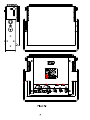
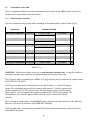
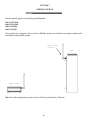
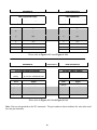
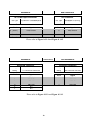
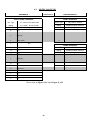
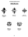
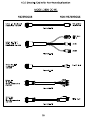
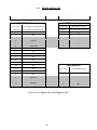
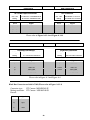
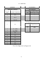
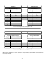
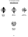
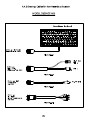
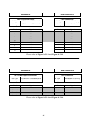
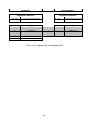
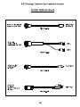
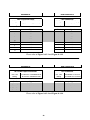
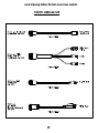
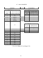
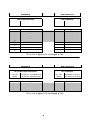
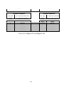
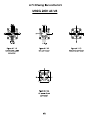
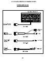
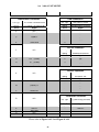
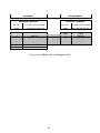
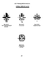
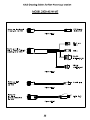
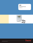
MODEL
MODEL
2800 AC
2800Rev D.
USER'S MANUAL
LAVERSAB INC.,
505 Gillingham Lane
Sugar Land TX, 77478
(281) 325-8300
FAX: (281) 328-8399
Email: [email protected]
Document Number : 9032
Date: Oct 10, 2011
WARRANTY
Laversab, Inc., warrants its products to conform to or exceed the specifications as
set forth in its catalogs in use at the time of sale and reserves the right, at its own
discretion, without notice and without making similar changes in articles previously
manufactured, to make changes in materials, designs, finish, or specifications. Laversab
Inc. warrants products of its own factory against defects of material or workmanship for a
period of one year from date of sale.
Liability of Laversab, Inc. under this warranty shall be limited to replacing, free of
charge (FOB Houston, Texas), any such parts proving defective within the period of this
warranty, but Laversab, Inc. will not be responsible for transportation charges,
consequential or incidental damages. No liability is assumed by Laversab for damages
that are caused by misuse or abuse of the product.
The warranty of Laversab Inc. is not made for products manufactured by others
which are illustrated and described in Laversab catalogs or incorporated in Laversab
products in essentially the same form as supplied by the original manufacturer.
i
COPYRIGHT NOTICE
Copyright (c) 2003-2007 by Laversab Inc. All rights reserved. The content of this manual
may not be reproduced in any form by any means, in part or in whole, without the prior
written permission of Laversab Inc.
DISCLAIMER
No representations or warranties are made with respect to the contents of this user's
manual. Further, Laversab Inc. reserves the right to revise this manual and to make
changes from time to time in the content hereof without obligation to notify any person of
such revision.
ii
WARNING
THE 2800 USES LINE VOLTAGES FOR ITS OPERATION WHICH ARE POTENTIALLY
DANGEROUS. IMPROPER OPERATION OF THIS EQUIPMENT MAY RESULT IN
PERSONAL INJURY OR LOSS OF LIFE. HENCE THE EQUIPMENT DESCRIBED IN
THIS MANUAL SHOULD BE OPERATED ONLY BY PERSONNEL TRAINED IN
PROCEDURES THAT WILL ASSURE SAFETY TO THEMSELVES, TO OTHERS AND
TO THE EQUIPMENT.
BEFORE PERFORMING ANY MAINTENANCE, TURN THE POWER OFF AND
DISCONNECT THE POWER CORD FROM THE POWER SOURCE.
iv
TABLE OF CONTENTS
Warranty
............................................................................................................................. I
Copyright notice, disclaimer
Revision History
.............................................................................................. ii
................................................................................................................... iii
Warning
............................................................................................................................. iv
Section 1:
Introduction .................................................................................................. 1
Section 2:
Safety
............................................................................................................. 4
Section 3:
Installation .....................................................................................................
3.1 Loading Software .................................................................................................
3.2 Mounting the 2800 ...............................................................................................
3.3 Connections to the 2800
....................................................................................
3.3.1 Non-hazardous locations ............................................................................
3.3.2 Hazardous locations ...................................................................................
6
6
6
8
8
8
Section 4:
Typical Use
................................................................................................... 12
Section 5:
Removal
Section 6:
Maintenance & Servicing
Section 7:
2800 Wireless Option ................................................................................... 16
........................................................................................................ 14
........................................................................... 15
v
Appendix A: Ext. Connections in Hazardous / Non-Hazardous Locations
........... 17
A.1
2800 (Standard model).................................................................................... 17
A.1.1
Drawings: Back Connectors .............................................................. 20
A.1.2
Drawings : Cables for Non-Hazardous Locations .......................... 21
A.2
2800-DC-M1 model ..................................................................................... 22
A.2.1
Drawings: Back Connectors .............................................................. 25
A.2.2
Drawings : Cables for Non-Hazardous Locations .......................... 26
A.3
2800-AC-M2 model ..................................................................................... 27
A.3.1
Drawings: Back Connectors .............................................................. 29
A.3.2
Drawings : Cables for Non-Hazardous Locations .......................... 30
A.4
2800-DC-M3 model ..................................................................................... 31
A.4.1
Drawings: Back Connectors .............................................................. 34
A.4.2
Drawings : Cables for Non-Hazardous Locations .......................... 35
A-5
2800-ACW-M4 model ................................................................................. 36
A.5.1
Drawings: Back Connectors .............................................................. 39
A.5.2
Drawings : Cables for Non-Hazardous Locations .......................... 40
A-6
2800-AC-M5 model ...................................................................................... 41
A.6.1
Drawings: Back Connectors .............................................................. 44
A.6.2
Drawings : Cables for Non-Hazardous Locations .......................... 45
A-7
2800-AC-M6 model ..................................................................................... 46
A.7.1
Drawings: Back Connectors .............................................................. 49
A.7.2
Drawings : Cables for Non-Hazardous Locations .......................... 50
A-8
2800-ACW-M7 model ................................................................................. 51
A.8.1
Drawings: Back Connectors .............................................................. 54
A.8.2
Drawings : Cables for Non-Hazardous Locations .......................... 55
Appendix B: Repair and Return Policies
........................................................................ 56
vi
SECTION 1
INTRODUCTION
The model 2800 Industrial computer is a PC-compatible computer that is specifically designed for use in
hazardous locations that are classified as Class 1 Division 2. Typical applications include rig-floor
monitoring and use in chemical plants. The rugged yet compact design of the 2800 makes it easy to
install and remove off rig-floors and makes it suitable for use under all weather conditions. The 2800 is
shown ifnFigure 1.1
The 2800 model is available in the following options:
2800-AC Rev D (Standard)
a. 2800-AC-M2 Rev B
b. 2800-AC-M5 Rev A
c. 2800-AC-M6 Rev B
2800-ACW Rev B (Standard) Wireless
a. 2800-ACW-M4 Rev B
b. 2800-ACW-M7 Rev B
2800-DC Rev D (Standard)
a. 2800-DC-M1 Rev B
b. 2800-DC-M3 Rev B
2800-DCW Rev B (Standard) Wireless
1
Standard Features:
•
Pentium M @ 1.8 GHz CPU or Atom 1.6 GHz CPU
•
15.0” TFT Color Ultra-Hibrite sunlight readable display with 1024 x 768 resolution
•
Auto-dimming of display brightness based on ambient light
•
High resolution, scratch resistant touch-screen
•
Fully sealed redundant mouse
•
Up to 1 GB System RAM
•
2.5” form factor HDD, minimum of 80 GB
•
2.5” form factor SSD, minimum 8 GB (optional)
•
110/220 VAC or 24 VDC nominal operating voltage
•
Two USB ports, barrier protected
•
One Serial Port, barrier protected
•
One Ethernet port, barrier protected
•
One external Keyboard port, barrier protected
•
Two 900 MHZ Wireless Radio with antenna (Wireless models only)
•
Internal heaters operating on 110/220 VAC allow operation between –40oC and +50oC
•
Sealed enclosure allows operation outdoors
•
Total weight of 25 lbs makes it easily portable
•
Dimensions of 16.5” wide, 14.5” high and 4.5” deep provide a small form factor
•
UL 1604 / CSA C22.2 No. 213 certified for use in Class 1 Division 2 locations Groups A, B, C and
D; Temp code T6.
2
SECTION 2
SAFETY
The following safety instructions must be followed to prevent possible hazards of fire, electrical shock
and bodily harm.
1.
WARNING : The model 2800 must be connected to an appropriate power source as indicated
on the information label on the rear panel of the unit.
2.
WARNING: AC Units: The circuit breaker for the power connection on the rear panel of the
unit must be in the OFF position such that the internal circuits are not energized, whenever the
power source is either connected or disconnected from the unit.
3.
WARNING: DC Units: The circuit breaker for the power connection on the rear panel of the
unit must be in the OFF position such that the internal circuits are not energized, whenever the
power source is either connected or disconnected from the unit.
4.
WARNING: The unit must never be opened or left open in a hazardous location. The rear
panel and the top heat sink must be securely fastened before the unit is introduced into a
hazardous location.
5.
WARNING: Do not install or operate this unit in an area where the temperature is outside the
limits indicated on the information label on the rear panel of the unit.
6.
WARNING: All connections made to the unit must strictly adhere to the rules set forth in
Section 3.2 of this manual.
7.
WARNING: There are no user-serviceable components inside this unit. The unit must not be
opened to repair or replace any components. If components are repaired or replaced by the user,
the unit may no longer be suitable for use in hazardous locations and may become an explosion
hazard.
8.
WARNING: The Model 2800 is suitable for use in Class I Division 2 (Groups A – D) hazardous
locations and non-hazardous locations only.
9.
CAUTION: Do not cover or obstruct the slots and fins on the top heat sink in a manner that
would restrict air flow between the slots or across the fins.
10.
CAUTION: Do not install the unit in an unstable manner that could cause it to tip over.
11.
CAUTION: Follow all instructions and warnings marked on the unit and also those included in
this manual.
4
Approvals:
The Model 2800 conforms to the following standards:
UL60950 / CSA 60950
CAN/CSA – C22.2 No. 60950.00
UL 1604
CAN / CSA – C22.2 No. 213-M1987
5
SECTION 3
INSTALLATION
The installation process consists of:
a.
b.
c.
3.1
Loading the application software onto the 2800
Mounting the 2800 on-site using an appropriate mounting bracket.
Making the connections to the 2800
Loading software
The 2800 is provided with a Windows operating system that is pre-installed with the network enabled.
All software must be loaded through the USB ports (USB1.1 std.) . It is not necessary to open the unit to
load the software.
If software modifications require that the unit be opened to have access to internal connectors, this must
be done at the Laversab facility. If the unit is opened by the user then it may severely impair the
hazardous location classification of the unit.
3.2
Mounting the 2800
A suitable mounting bracket may be fabricated by the user based on the user’s mounting requirements.
Figure 3.1 shows a suggested mounting bracket for mounting the 2800 on a flat plate or on a pipe stand
with an optional adapter. The mounting bracket should be fastened to the four mounting studs
provided on the rear panel of the unit. The studs are ¾ inch in length with a thread size of 5/16 – 18.
WARNING: The mounting bracket should not cover any of the markings and warnings on the rear
panel of the 2800.
WARNING: The mounting bracket should not cover any of the connectors or the circuit breakers on
the rear panel of the 2800.
WARNING: The mounting bracket should not restrict air-flow between the fins of the top heat-sink.
CAUTION: The mounting bracket should not cover the photo-resistor lens on the front of the 2800.
6
3.3
Connections to the 2800
There is a significant difference on how connections may be made to the 2800 based on whether the
location of use is hazardous or non-hazardous.
3.3.1
Non-hazardous locations
The unit is provided with external cables according to the model option. (refer to Table 3.3.1.a)
2800 Models
2800-AC Rev D (Standard)
CABLES PROVIDED
AC POWER
RS-232 / 2 USB
KEYBOARD
LAN
a. 2800-AC-M2 Rev B
AC POWER
USB / LAN
KB / MOUSE
b. 2800-AC-M5 Rev A
AC POWER
RS-232 / 2 USB
KEYBOARD
LAN
c. 2800-AC-M6 Rev B
AC POWER
RS-232 / USB
KB WITH STAND
LAN
2800-ACW Rev B (Standard) AC POWER
RS-232 / 2 USB
KEYBOARD
LAN
a. 2800-ACW-M4 Rev B
AC POWER
2 USB
KEYBOARD
LAN
b. 2800-ACW-M7 Rev B
AC POWER
USB/RS-232/RS-422/XDR
KEYBOARD
LAN
2800-DC Rev D (Standard)
DC POWER
RS-232 / 2 USB
KEYBOARD
LAN
a. 2800-DC-M1 Rev B
DC POWER
2 USB
KEYBOARD
LAN
b. 2800-DC-M3 Rev B
DC POWER
RS-232 / USB
2800-DCW Rev B (Standard) DC POWER
RS-232 / 2 USB
STAND ALONE KB LAN
KEYBOARD
LAN
Table 3.3.1.a
WARNING: All the above cables are for use in non-hazardous locations only. Using these cables in
hazardous locations may impair the hazardous location classification of the unit.
The AC power cable is terminated in a NEMA 5-15 plug and may only be connected to a power source
of 110/220 VAC, 50/60 Hz.
The DC power cable must be connected to an external 24 Volts (+/- 2 volts) DC power
source. The termination on the end of the power cable marked ‘+’ must be connected to
positive output of the 24 VDC power source. The termination on the end of the power
cable marked ‘-’ must be connected to negative output of the 24 VDC power source. The
termination on the end of the power cable marked ‘E’ must be connected to Earth
Ground.
The LAN cable is terminated in a standard RJ-45 plug which must be connected to any 10/100 M-bit
Ethernet LAN device that adheres to the IEEE 802.3 standard.
The Keyboard cable is terminated in a standard PS2 female connector that may be connected to any
standard PS2 keyboard.
8
The Serial / USB cable is split up into 3 separate terminations. The terminations labeled ‘COM1’,
‘COM2’ provide a DB-9 male connector which may be connected to any EIA RS-232C connection. The
terminations labeled ‘USB1’, ‘USB2’ provides a Type A Jack (4 position) which may be connected to any
device with the USB standard ; due to the safety barriers the USB can only support full speed standard
(USB 1.1) and since they are current limited, it is recommended to use externally powered devices when
possible.
The drawings and pin-outs of these cables are provided in Appendix B.
3.3.2
Hazardous locations
The user is required to provide all the external cables for use in hazardous locations. The cabling and
connection methods and restrictions are detailed below. The Control Drawing for all connections to the
2800 is shown in Figure A-1.
1. AC Power cable:
The pin-out for the AC POWER INPUT connector on the rear panel of the 2800 is provided in Appendix
A. The mating connector is also listed in Appendix A. The External 110 VAC, 60Hz or 220 VAC, 50 Hz
power source must be located in a non-hazardous location.
2. DC Power cable:
The pin-out for the DC POWER INPUT connector on the rear panel of the 2800 is
provided in Appendix A. The mating connector is also listed in Appendix A. The
External 24 VDC (+/-2 VDC) power source must be located in a non-hazardous location.
WARNING: The power cord used must adhere to the following rules:
a. The power cord must be approved for “extra hard” usage.
b. The section of the power cord that runs through a hazardous area must be protected by rigid
conduit with liquid-tight ends.
c. Only the last 3 feet before the power cord mates to the 2800 may be left unprotected without the
rigid conduit.
d. The power cord must be terminated into the external AC or DC power source as shown in
Figure A-1
WARNING: Make sure that the POWER circuit breaker on the rear panel of the 2800 is in the OFF
position before connecting or disconnecting the POWER INPUT connector. Do not connect or
disconnect the POWER INPUT connector when the circuits are energized.
WARNING: Ensure that the external power source is OFF before connecting or disconnecting the
POWER INPUT connector.
3. LAN cable
9
The pin-out for the LAN connector on the rear panel of the 2800 is provided in Appendix A. The
mating connector is also listed in Appendix A.
WARNING: The LAN cable may only be terminated into a 10/100 M-bit Ethernet LAN device that
adheres to the IEEE 802.3 standard. The Control Drawing for this connection is shown in Figure A-1.
A shielded CAT-5 cable may be used to provide this connection to the 2800. Although no special cable
protection is required in a hazardous location, it is recommended that the LAN cable be run in the same
rigid conduit used for the power cable.
WARNING: Make sure that the POWER and circuit breaker on the rear panel of the 2800 are in the
OFF position before connecting or disconnecting the LAN connector. Do not connect or disconnect the
LAN connector when the circuits are energized.
4. Keyboard cable
The pin-out for the keyboard connector on the rear panel of the 2800 is provided in Appendix A. The
mating connector is also listed in Appendix A.
For details on the keyboard cable, please refer to the Control Drawing shown on Figure A-1.
WARNING: The keyboard cable may be connected only to an intrinsically safe keyboard per the
Control Drawing shown in Figure A-1. The recommended keyboard is the model KBM-IS.
WARNING: The keyboard cable must be terminated in a locking connector. The intrinsically safe
keyboard must be able to mate to this locking connector.
WARNING: Do not connect or disconnect the keyboard when the circuits are energized. Make sure
that the POWER circuit breaker on the rear panel of the 2800 is in the OFF position before connecting or
disconnecting the keyboard.
10
5. USB/Serial cable
WARNING: The USB part of the cable may only be terminated into a connection that adheres to the
USB 1.1 standard. The Control Drawing for this connection is shown in Figure A-1.
WARNING: The Serial part of the cable may only be terminated into a connection that adheres to the
EIA RS-232C standard. The Control Drawing for this connection is shown in Figure A-1.
WARNING: Do not connect or disconnect the USB/Serial connector when the circuits are energized.
Make sure that the POWER and circuit breaker on the rear panel of the 2800 are in the OFF position
before connecting or disconnecting the USB/Serial connector.
A shielded cable may be used to provide the USB/Serial connection to the 2800. Although no special
cable protection is required in a hazardous location, it is recommended that this communication cable
be run in the same rigid conduit used for the power cable.
11
SECTION 4
TYPICAL USE
After the 2800 has been installed per the instructions provided in Section 3 of this manual, the unit may
be turned ON for operation in the following sequence:
1. Turn ON the external power source (AC or DC).
2. Turn ON the devices that provide the Ethernet and RS232 interfaces in the non-hazardous
location.
3. Turn ON the POWER circuit breaker (AC or DC) on the 2800.
If the ambient temperature is below 5oC then the 2800 may not boot up immediately. The internal
heaters and fans will start operating and attempt to bring the temperature inside the 2800 above 5oC.
While this process is on-going, the heaters LED will turn on indicating that the heaters are operating.
The heaters may operate for up to 30 minutes before the internal temperature rises above 5oC, at which
point the computer section of the 2800 will boot up.
When the computer section of the 2800 is starting to boot up, the backlight on the display will turn on
and the display will be completely white for a period of about 2 to 5 seconds. Thereafter, the boot-up
screen will be displayed.
During normal use, the application software will communicate through the LAN and/or the Serial port
and show the necessary information on the display. The keyboard may be used as an input device by
the user, but typically, the touch-screen and/or the mouse on the front panel, are the only input devices
used.
CAUTION: Do not use a sharp object to “touch” the touch-screen. Scratching the touch-screen
surface in any way will cause the touch-screen to mal-function.
The mouse on the front panel is configured such that the circular button in the center is the cursor
movement button, and the two buttons on either side of it are the left and right click keys. The circular
button is pressure sensitive. The harder it is pressed, the faster is the cursor movement.
The mouse and the touch-screen may be used alternately. This means that they are both active at all
times and cursor movements and icon selections etc. may be done by either one of them. The “rightclick” function on the touch-screen is available and can be configured through the driver application.
Cursor movement and icon selection is easier with the touch-screen whereas, “dragging” is easier with
the mouse.
If the touch-screen is inoperative, the mouse will still provide the user with input capability. Thereby,
the mouse provides redundancy for the touch-screen.
12
The photo-resistor lens on the front of the unit must be kept un-obstructed and clean during normal
operation. This will allow the auto-dimming circuit to properly regulate the brightness of the display
based on the ambient light conditions.
WARNING: During normal operation the user must not alter any of the connections to the 2800,
including the keyboard connection. Before altering (connecting or disconnecting) any connection, both
circuit breakers on the 2800 must be turned OFF so that all internal circuits are de-energized. Failure to
do so may create an explosion hazard.
13
SECTION 5
REMOVAL
While removing (de-installing) the 2800 from normal operation, follow the sequence shown below:
WARNING: Do not disconnect ANY connectors while circuits are energized.
1. Turn OFF the POWER circuit breaker on the 2800.
2. Turn OFF the external power source located in the non-hazardous area.
3. Turn OFF the devices in the non-hazardous area that provide the LAN and RS232 interfaces to
the 2800.
4. Disconnect the POWER INPUT connector from the 2800.
5. Disconnect the LAN connector.
6. Disconnect the Serial connector.
7. Disconnect the keyboard connector.
8. Remove the 2800 from its mounting stand and move it out of the hazardous location.
WARNING: Not following the above sequence may induce an explosion hazard
14
SECTION 6
MAINTENANCE & SERVICING
6.1
MAINTENANCE
The only regular maintenance procedures required on the 2800 are:
a. Clean the touch-screen with water or any commercial window cleaner, using a clean, soft, lintfree cloth. Care must be taken not to scratch the touch-screen during the cleaning process. Do
not use any abrasive substance, or any organic solvents to clean the touch-screen.
b. Clean the photo-resistor lens in the same manner as described in ‘a.’ above.
c. Clean the top heat-sink to remove all dirt and foreign objects that may be stuck between the fins
of the heat-sink.
WARNING: Do NOT pressure-wash the 2800.
6.2
SERVICING
CAUTION: Risk of explosion if battery is replaced by an incorrect type. Dispose off used batteries in
the prescribed manner.
WARNING: Substitution of components is strictly prohibited
WARNING: The Model 2800 does not contain any user-serviceable or user-replaceable components.
The 2800 must not be opened by the user in an attempt to repair or service the unit. Doing so may
severely impair the hazardous location classification of the unit. All repairs and servicing of the unit
can only be performed at the Laversab facility.
15
SECTION 7
WIRELESS OPTION
Wireless option applies to the following 2800 models:
2800-ACW (Std)
2800-DCW (Std)
2800-ACW-M4
2800-ACW-M7
These models are equipped with a set of two 900 Mhz radios; one inside the unit (master radio) and a
stand-alone radio (remote radio).
Master Radio
(inside)
2800
Remote Radio
Note: For radio configuration, please refer to “Wireless Radio Setup” Manual.
16
APPENDIX A
EXTERNAL CONNECTIONS (HAZARDOUS / NON HAZARDOUS) LOCATIONS
The external connectors, pin-outs and connection details shown below reference the Control Drawing
shown in Figure A-1. Individual connector drawings are shown in Figures A2 through A6.
A.1 MODEL 2800 STANDARD
Interconnect
HAZARDOUS
NON HAZARDOUS
USB/SERIAL Connector
USB connectors
CN. Type
ITT Cannon KPT02A14-19S
Conn. Type
Std. USB "A" Socket
Mating
Pin #
ITT Cannon KPT06J14-19P
Signal
Mating
Pin #
Standard USB A connector
Signal
A
N.C.
B
USB1 +5V
1
+5 V
C
USB1 D-
2
D-
D
USB1 D+
3
D+
E
USB1 GND
4
GND
F
N.C.
RS-232 connector
CN. Type
Standard DB-9 male
Mating
Pin #
Standard DB-9 female
Signal
G
RX
(COM1)
2
RX
H
TX
(COM1)
3
TX
J
GND (COM1)
5
GND
K
USB2 D-
L
USB2 D+
M
USB2 GND
N
N.C.
P
N.C.
R
USB2 +5V
S
N.C.
T
N.C.
U
N.C.
V
N.C.
Please refer to Figure A.1.1-1 and Figure A.1.2-2
17
HAZARDOUS
Interconnect
NON HAZARDOUS
LAN Connector 2800
LAN connector
CN. Type
ITT Cannon KPT02A12-8S
CN. Type
Standard RJ-45 plug
Mating
ITT Cannon KPT06J12-8P
Mating
Standard RJ-45 socket
Pin #
Signal
Pin #
Signal
A
TD +
1
TD +
B
TD -
2
TD -
C
RD -
6
RD -
D
RD +
3
RD +
E
N.C.
4
N.C.
F
N.C.
5
N.C.
G
N.C.
7
N.C.
H
N.C.
8
N.C.
Please refer to Figure A.1.1-2 and Figure A.1.2-3
HAZARDOUS
Interconnect
DC Power Input Connector
NON HAZARDOUS
24 VDC Power supply
CN. Type
B. Harrison 1R5G06A20A120
Mating
B. Harrison 105000A02F060
Pin #
Signal
Color
Signal
N.C.
N.C.
+24 VDC
O (Orange)
B (Black)
+24 VDC
Orange
Black
G (Green)
Earth Ground
Green
Earth Ground
W (White)
24 VDC Return
White
24 VDC return
N.C.
Red
N.C.
R (Red)
Please refer to Figure A.1.1-5 and Figure A1.2-4
Note: Pins are not marked on the DC connector. The pin numbers shown indicate the wire color used
for each pin internally.
18
HAZARDOUS
Interconnect
NON HAZARDOUS
AC Power Input Connector
AC connector
CN. Type
B. Harrison 1R3G06A20A120
CN. Type
Std NEMA L6-15 Plug
Mating
B. Harrison 103000A01F060
Mating
Std. NEMA L6-15 socket
Pin #
Signal
Pin #
Signal
G (Green)
Earth Ground
G
Earth Ground
W (White)
Neutral
Y
Neutral
B (Black)
Line
X
Line
Please refer to Figure A.1.1-4 and Figure A.1.2-5
HAZARDOUS
Interconnect
Keyboard connector
NON HAZARDOUS
Keyboard connector
CN. Type
ITT Cannon KPT02A10-6S
CN. Type
Std. PS2 female connector
Mating
ITT Cannon KPT06J10-6P
Mating
Std. PS2 male connector
Pin #
Signal
A
B
C
D
E
F
KBD CLK
KBD DATA
KBD +5V
KBD GND
N.C
N.C
Pin #
5
1
4
3
Signal
KBD CLK
KBD DATA
KBD +5V
KBD GND
Please refer to Figure A1.1-3 and Figure A.1.2-1
19
A.2: MODEL 2800-DC-M1
HAZARDOUS
Interconnect
NON HAZARDOUS
USB1/USB2 Connector
USB1 connector
CN. Type
ITT Cannon KPT02A14-19S
Conn. Type
Std. USB "A" Socket
Mating
Pin #
ITT Cannon KPT06J14-19P
Signal
Mating
Pin #
Standard USB A connector
Signal
A
N.C.
B
USB1 +5V
1
+5 V
C
USB1 D-
2
D-
D
USB1 D+
3
D+
E
USB1 GND
4
GND
F
N.C.
USB2 connector
G
N.C.
Conn. Type
Std. USB "A" Socket
H
N.C.
J
N.C.
Mating
Pin #
Standard USB A connector
Signal
K
USB2 D-
2
D-
L
USB2 D+
3
D+
M
USB2 GND
4
GND
N
N.C.
P
N.C.
R
USB2 +5V
1
+5 V
S
N.C.
T
N.C.
U
N.C.
V
N.C.
Please refer to Figure A.2.1-1 and Figure A.2.2-1
22
HAZARDOUS
Interconnect
NON HAZARDOUS
LAN Connector
LAN connector
CN. Type
ITT Cannon KPT02A12-8S
CN. Type
Standard RJ-45 plug
Mating
ITT Cannon KPT06J12-8P
Mating
Standard RJ-45 socket
Pin #
Signal
Pin #
Signal
A
TD +
1
TD +
B
TD -
2
TD -
C
RD -
6
RD -
D
RD +
3
RD +
E
N.C.
4
N.C.
F
N.C.
5
N.C.
G
N.C.
7
N.C.
H
N.C.
8
N.C.
Please refer to Figure A.2.1-2 and Figure A.2.2-3
HAZARDOUS
Interconnect
DC Power Input Connector
NON HAZARDOUS
24 VDC Power supply
CN. Type
B. Harrison 1R5G06A20A120
Mating
B. Harrison 105000A02F060
Pin #
Signal
Color
Signal
N.C.
N.C.
+24 VDC
O (Orange)
B (Black)
+24 VDC
Orange
Black
G (Green)
Earth Ground
Green
Earth Ground
W (White)
24 VDC Return
White
24 VDC return
N.C.
Red
N.C.
R (Red)
Please refer to Figure A.2.1-5 and Figure A.2.2-4
Note: Pins are not marked on the DC connector. The pin numbers shown indicate the wire color used
for each pin internally.
23
HAZARDOUS
Interconnect
NON HAZARDOUS
AC Power Input Connector
AC connector
CN. Type
B. Harrison 1R3G06A20A120
CN. Type
Std NEMA L6-15 Plug
Mating
B. Harrison 103000A01F060
Mating
Std. NEMA L6-15 socket
Pin #
Signal
Pin #
Signal
G (Green)
Earth Ground
G
Earth Ground
W (White)
Neutral
Y
Neutral
B (Black)
Line
X
Line
Please refer to Figure A.2.1-4 and Figure A.2.2-5
HAZARDOUS
Interconnect
Keyboard connector
NON HAZARDOUS
Keyboard connector
CN. Type
ITT Cannon KPT02A10-6S
CN. Type
Std. PS2 female connector
Mating
ITT Cannon KPT06J10-6P
Mating
Std. PS2 male connector
Pin #
Signal
A
B
C
D
E
F
KBD CLK
KBD DATA
KBD +5V
KBD GND
N.C
N.C
Pin #
5
1
4
3
Signal
KBD CLK
KBD DATA
KBD +5V
KBD GND
Please refer to Figure A.2.1-3 and Figure A.2.2-1
24
A.3: MODEL 2800-AC-M2
HAZARDOUS
Interconnect
NON HAZARDOUS
USB/SERIAL Connector
USB connectors
CN. Type
ITT Cannon KPT02A14-19S
Conn. Type
Std. USB "A" Socket
Mating
Pin #
ITT Cannon KPT06J14-19P
Signal
Mating
Pin #
Standard USB A connector
Signal
A
N.C.
B
USB1 +5V
1
+5 V
C
USB1 D-
2
D-
D
USB1 D+
3
D+
E
F
USB1 GND
N.C.
4
GND
G
N.C.
H
N.C.
J
N.C.
K
N.C.
L
N.C.
M
N.C.
N
N.C.
CN. Type
Standard RJ-45 plug
P
N.C.
R
N.C.
Mating
Pin #
Standard RJ-45 socket
Signal
S
LAN TD +
1
TD +
T
LAN TD -
2
TD -
U
LAN RD -
6
RD -
V
LAN RD +
3
RD +
LAN connector
Please refer to Figure A.3.1-1 and Figure A.3.2-2
27
HAZARDOUS
Interconnect
NON HAZARDOUS
AC Power Input Connector
AC connector
CN. Type
B. Harrison 1R3G06A20A120
CN. Type
Std NEMA L6-15 Plug
Mating
B. Harrison 103000A01F060
Mating
Std. NEMA L6-15 socket
Pin #
Signal
Pin #
Signal
G (Green)
Earth Ground
G
Earth Ground
W (White)
Neutral
Y
Neutral
B (Black)
Line
X
Line
Please refer to Figure A.3.1-4 and Figure A.3.2-3
HAZARDOUS
Interconnect
Keyboard connector
NON HAZARDOUS
Keyboard connector
CN. Type
ITT Cannon KPT02A10-6S
CN. Type
Std. PS2 female connector
Mating
ITT Cannon KPT06J10-6P
Mating
Std. PS2 male connector
Pin #
Signal
A
B
C
D
E
F
KBD CLK
KBD DATA
KBD +5V
KBD GND
MOUSE CLK
MOUSE DATA
Pin #
5 keyboard
1 keyboard
4 kb/m
3 kb/m
5 mouse
1 mouse
Signal
KBD CLK
KBD DATA
KBD +5V
KBD GND
MOUSE CLK
MOUSE DATA
Please refer to Figure A-1 and Figure A-6
Black Box Connector on 2800-AC-M2 (Please refer to Figure A.3.1-2)
Connector type :
Mating connector:
Pin-out:
ITT Cannon MS3102E14S-5P
ITT Cannon MS3106F14S-5S
Pin #
Signal
A
RCV+
B
RCV-
C
XTM+
D
XMT-
E
BB terminal strip
28
A.4 2800-DC-M3
Interconnect
HAZARDOUS
NON HAZARDOUS
USB/SERIAL Connector
USB connectors
CN. Type
ITT Cannon KPT02A14-19S
Conn. Type
Std. USB "A" Socket
Mating
Pin #
ITT Cannon KPT06J14-19P
Signal
Mating
Pin #
Standard USB A connector
Signal
A
N.C.
B
USB1 +5V
1
+5 V
C
USB1 D-
2
D-
D
USB1 D+
3
D+
E
USB1 GND
4
GND
F
N.C.
RS-232 connector
CN. Type
Standard DB-9 male
Mating
Pin #
Standard DB-9 female
Signal
G
RX
(COM1)
2
RX
H
TX
(COM1)
3
TX
J
GND (COM1)
5
GND
K
N.C.
L
N.C.
M
N.C.
N
N.C.
P
N.C.
R
N.C.
S
N.C.
T
N.C.
U
N.C.
V
N.C.
Please refer to Figure A.4.1-1 and Figure A.4.2-2
31
HAZARDOUS
Interconnect
NON HAZARDOUS
LAN Connector 2800
LAN connector
CN. Type
ITT Cannon KPT02A12-8S
CN. Type
Standard RJ-45 plug
Mating
ITT Cannon KPT06J12-8P
Mating
Standard RJ-45 socket
Pin #
Signal
Pin #
Signal
A
TD +
1
TD +
B
TD -
2
TD -
C
RD -
6
RD -
D
RD +
3
RD +
E
N.C.
4
N.C.
F
N.C.
5
N.C.
G
N.C.
7
N.C.
H
N.C.
8
N.C.
Please refer to Figure A.4.1-2 and Figure A.4.2-3
HAZARDOUS
Interconnect
DC Power Input Connector
NON HAZARDOUS
24 VDC Power supply
CN. Type
B. Harrison 1R5G06A20A120
Mating
B. Harrison 105000A02F060
Pin #
Signal
Color
Signal
N.C.
N.C.
+24 VDC
O (Orange)
B (Black)
+24 VDC
Orange
Black
G (Green)
Earth Ground
Green
Earth Ground
W (White)
24 VDC Return
White
24 VDC return
N.C.
Red
N.C.
R (Red)
Please refer to Figure A.4.1-4 and Figure A.4.2-4
Note: Pins are not marked on the DC connector. The pin numbers shown indicate the wire color used
for each pin internally.
32
HAZARDOUS
Interconnect
NON HAZARDOUS
Keyboard connector
Keyboard connector
CN. Type
ITT Cannon KPT02A10-6S
CN. Type
Mating
ITT Cannon KPT06J10-6P
Mating
Pin #
Signal
A
B
C
D
E
F
KBD CLK
KBD DATA
KBD +5V
KBD GND
N.C
N.C
Pin #
5
1
4
3
Please refer to Figure A.4.1-3 and Figure A.4.2-1
33
Std. PS2 female connector
Std. PS2 male connector
Signal
KBD CLK
KBD DATA
KBD +5V
KBD GND
A.5: 2800-ACW-M4
HAZARDOUS
Interconnect
NON HAZARDOUS
USB/SERIAL Connector
USB connectors
CN. Type
ITT Cannon KPT02A14-19S
Conn. Type
Std. USB "A" Socket
Mating
Pin #
ITT Cannon KPT06J14-19P
Signal
Mating
Pin #
Standard USB A connector
Signal
A
N.C.
B
USB1 +5V
1
+5 V
C
USB1 D-
2
D-
D
USB1 D+
3
D+
E
USB1 GND
4
GND
F
N.C.
USB connectors
G
N.C.
Conn. Type
Std. USB "A" Socket
H
N.C.
J
N.C.
Mating
Pin #
Standard USB A connector
Signal
K
USB2 D-
2
D-
L
USB2 D+
3
D+
M
USB2 GND
4
GND
N
N.C.
P
N.C.
R
USB2 +5V
1
+5 V
S
N.C.
T
N.C.
U
N.C.
V
N.C.
Please refer to Figure A.5.1-1 and Figure A.5.2-2
36
HAZARDOUS
Interconnect
NON HAZARDOUS
LAN Connector 2800
LAN connector
CN. Type
ITT Cannon KPT02A12-8S
CN. Type
Standard RJ-45 plug
Mating
ITT Cannon KPT06J12-8P
Mating
Standard RJ-45 socket
Pin #
Signal
Pin #
Signal
A
TD +
1
TD +
B
TD -
2
TD -
C
RD -
6
RD -
D
RD +
3
RD +
E
N.C.
4
N.C.
F
N.C.
5
N.C.
G
N.C.
7
N.C.
H
N.C.
8
N.C.
Please refer to Figure A.5.1-2 and Figure A.5.2-3
HAZARDOUS
Interconnect
NON HAZARDOUS
AC Power Input Connector
AC connector
CN. Type
B. Harrison 1R3G06A20A120
CN. Type
Mating
B. Harrison 103000A01F060
Pin #
Signal
Pin #
Signal
G (Green)
Earth Ground
G
Earth Ground
W (White)
Neutral
Y
Neutral
B (Black)
Line
X
Line
Mating
Std. NEMA L6-15 socket
Please refer to Figure A.5.1-4 and Figure A.5.2-4
37
Std NEMA L6-15 Plug
HAZARDOUS
Interconnect
NON HAZARDOUS
Keyboard connector
Keyboard connector
CN. Type
ITT Cannon KPT02A10-6S
CN. Type
Mating
ITT Cannon KPT06J10-6P
Mating
Pin #
Signal
A
B
C
D
E
F
KBD CLK
KBD DATA
KBD +5V
KBD GND
N.C
N.C
Pin #
5
1
4
3
Please refer to Figure A.5.1-3 and Figure A.5.2-1
38
Std. PS2 female connector
Std. PS2 male connector
Signal
KBD CLK
KBD DATA
KBD +5V
KBD GND
A.6: 2800-AC-M5 MODEL
Interconnect
HAZARDOUS
NON HAZARDOUS
USB/SERIAL Connector
USB connectors
CN. Type
ITT Cannon KPT02A14-19S
Conn. Type
Std. USB "A" Socket
Mating
Pin #
ITT Cannon KPT06J14-19P
Signal
Mating
Pin #
Std. USB “A” connector
Signal
A
N.C.
B
USB1 +5V
1
+5 V
C
USB1 D-
2
D-
D
USB1 D+
3
D+
E
USB1 GND
4
GND
F
N.C.
RS-232 connector
CN. Type
Standard DB-9 male
Mating
Pin #
Standard DB-9 female
Signal
G
RX
(COM1)
2
RX
H
TX
(COM1)
3
TX
J
GND (COM1)
5
GND
K
USB2 D-
L
USB2 D+
M
USB2 GND
N
N.C.
P
N.C.
R
USB2 +5V
S
N.C.
T
N.C.
U
N.C.
V
N.C.
Please refer to Figure A.6.1-1 and Figure A.6.2-2
41
HAZARDOUS
NON HAZARDOUS
LAN Connector 2800
LAN connector
CN. Type
ITT Cannon KPT02A12-8S
CN. Type
Standard RJ-45 plug
Mating
ITT Cannon KPT06J12-8P
Mating
Standard RJ-45 socket
Pin #
Signal
Pin #
Signal
A
TD +
1
TD +
B
TD -
2
TD -
C
RD -
6
RD -
D
RD +
3
RD +
E
N.C.
4
N.C.
F
N.C.
5
N.C.
G
N.C.
7
N.C.
H
N.C.
8
N.C.
Please refer to Figure A.6.1-2 and Figure A.6.2-3
HAZARDOUS
Interconnect
NON HAZARDOUS
AC Power Input Connector
AC connector
CN. Type
B. Harrison 1R3G06A20A120
CN. Type
Std NEMA L6-15 Plug
Mating
B. Harrison 103000A01F060
Mating
Std. NEMA L6-15 socket
Pin #
Signal
Pin #
Signal
G (Green)
Earth Ground
G
Earth Ground
W (White)
Neutral
Y
Neutral
B (Black)
Line
X
Line
Please refer to Figure A.6.1-4 and Figure A.6.2-4
42
HAZARDOUS
Interconnect
Keyboard connector
NON HAZARDOUS
Keyboard connector
CN. Type
ITT Cannon KPT02A10-6S
CN. Type
Std. PS2 female connector
Mating
ITT Cannon KPT06J10-6P
Mating
Std. PS2 male connector
Pin #
Signal
A
B
C
D
E
F
KBD CLK
KBD DATA
KBD +5V
KBD GND
N.C
N.C
Pin #
5
1
4
3
Signal
KBD CLK
KBD DATA
KBD +5V
KBD GND
Please refer to Figure A.6.1-3 and Figure A.6.2-1
43
A.7: 2800-AC-M6 MODEL
Interconnect
HAZARDOUS
NON HAZARDOUS
USB/SERIAL Connector
USB connectors
CN. Type
ITT Cannon KPT02A14-19S
Conn. Type
Std. USB "A" Socket
Mating
Pin #
ITT Cannon KPT06J14-19P
Signal
Mating
Pin #
Standard USB A connector
Signal
A
N.C.
B
USB1 +5V
1
+5 V
C
USB1 D-
2
D-
D
USB1 D+
3
D+
E
USB1 GND
4
GND
F
N.C.
RS-232 connector
CN. Type
Standard DB-9 male
Mating
Pin #
Standard DB-9 female
Signal
G
RX
(COM1)
2
RX
H
TX
(COM1)
3
TX
J
GND (COM1)
5
GND
K
N.C.
L
N.C.
M
N.C.
N
N.C.
P
N.C.
R
N.C.
S
N.C.
T
N.C.
U
N.C.
V
N.C.
Please refer to Figure A.7.1-1 and Figure A.7.2-2
46
HAZARDOUS
Interconnect
NON HAZARDOUS
LAN Connector 2800
LAN connector
CN. Type
ITT Cannon KPT02A12-8S
CN. Type
Standard RJ-45 plug
Mating
ITT Cannon KPT06J12-8P
Mating
Standard RJ-45 socket
Pin #
Signal
Pin #
Signal
A
TD +
1
TD +
B
TD -
2
TD -
C
RD -
6
RD -
D
RD +
3
RD +
E
N.C.
4
N.C.
F
N.C.
5
N.C.
G
N.C.
7
N.C.
H
N.C.
8
N.C.
Please refer to Figure A.7.1-2 and Figure A.7.2-3
HAZARDOUS
Interconnect
NON HAZARDOUS
AC Power Input Connector
AC connector
CN. Type
B. Harrison 1R3G06A20A120
CN. Type
Std NEMA L6-15 Plug
Mating
B. Harrison 103000A01F060
Mating
Std. NEMA L6-15 socket
Pin #
Signal
Pin #
Signal
G (Green)
Earth Ground
G
Earth Ground
W (White)
Neutral
Y
Neutral
B (Black)
Line
X
Line
Please refer to Figure A.7.1-4 and Figure A.7.2-4
47
HAZARDOUS
Interconnect
Keyboard connector
NON HAZARDOUS
Keyboard connector
CN. Type
ITT Cannon KPT02A10-6S
CN. Type
Std. PS2 female connector
Mating
ITT Cannon KPT06J10-6P
Mating
Std. PS2 male connector
Pin #
Signal
A
B
C
D
E
F
KBD CLK
KBD DATA
KBD +5V
KBD GND
MOUSE CLK
MOUSE DATA
Pin #
5 keyboard
1 keyboard
4 kb/m
3 kb/m
5 mouse
1 mouse
Signal
KBD CLK
KBD DATA
KBD +5V
KBD GND
MOUSE CLK
MOUSE DATA
Please refer to Figure A.7.1-3 and Figure A.7.2-1
48
A.8 2800-AC-M7 MODEL
HAZARDOUS
NON HAZARDOUS
Interconnect
USB connectors
USB/SERIAL Connector
CN. Type
ITT Cannon KPT02A14-19S
CN. Type
Std. USB "A" Socket
Mating
Pin #
ITT Cannon KPT06J14-19P
Signal
Mating
Pin #
Standard USB A connector
Signal
A
N.C.
B
USB4 +5V
1
+5 V
C
USB4 D-
2
D-
D
USB4 D+
3
D+
E
USB4 GND
4
GND
RS-232 connector
F
N.C.
CN. Type
Standard DB-9 male
Mating
Pin #
Standard DB-9 female
Signal
RX
G
RX
(COM2)
2
H
TX
(COM2)
3
TX
J
GND (COM2)
5
GND
RS-422 connector
K
N.C.
CN. Type
KPT01F12-10S
Mating
Pin #
KPT06J12-10P
Signal
L
RS422-TX+
4
TX+
M
RS422-TX-
5
TX-
N
RS422-RX+
1
RX+
P
RS422-RX-
2
RX-
Transducer connector
R
S
T
U
V
N.C.
XDR-V+
XDR-GND
N.C.
XDR-24V
CN. Type
ITT Cannon KPT01A10-6P
Mating
Pin #
ITT Cannon KPT02A10-6S
Signal
B
F
XDR-V+
XDR-GND
A
XDR-24V
Please refer to Figure A.8.1-1 and Figure A.8.2-2
51
HAZARDOUS
Interconnect
NON HAZARDOUS
LAN Connector 2800
LAN connector
CN. Type
ITT Cannon KPT02A12-8S
CN. Type
Standard RJ-45 plug
Mating "G"
ITT Cannon KPT06J12-8P
Mating
Standard RJ-45 socket
Pin #
Signal
Pin #
Signal
A
TD +
1
TD +
B
TD -
2
TD -
C
RD -
6
RD -
D
RD +
3
RD +
E
N.C.
4
N.C.
F
N.C.
5
N.C.
G
N.C.
7
N.C.
H
N.C.
8
N.C.
Please refer to Figure A.8.1-2 and Figure A.8.2-3
HAZARDOUS
Interconnect
NON HAZARDOUS
AC Power Input Connector
AC connector
CN. Type
B. Harrison 1R3G06A20A120
CN. Type
Std NEMA L6-15 Plug
Mating
B. Harrison 103000A01F060
Mating
Std. NEMA L6-15 socket
Pin #
Signal
Pin #
Signal
G (Green)
Earth Ground
G
Earth Ground
W (White)
Neutral
Y
Neutral
B (Black)
Line
X
Line
Please refer to Figure A.8.1-4 and Figure A.8.2-4
52
HAZARDOUS
Interconnect
Keyboard connector
NON HAZARDOUS
Keyboard connector
CN. Type
ITT Cannon KPT02A10-6S
CN. Type
Std. PS2 female connector
Mating
ITT Cannon KPT06J10-6P
Mating
Std. PS2 male connector
Pin #
Signal
A
B
C
D
E
F
KBD CLK
KBD DATA
KBD +5V
KBD GND
N.C
N.C
Pin #
5
1
4
3
Signal
KBD CLK
KBD DATA
KBD +5V
KBD GND
Please refer to Figure A.8.1-3 and Figure A.8.2-1
53
APPENDIX B
REPAIR AND RETURN POLICIES
If it is determined that the product is defective, please call Laversab customer service department: (281)
325-8300 or e-mail <[email protected]> for further assistance.
Before shipping any equipment to Laversab for repair, please call the customer service department at
(281) 325-8300 or e-mail to <[email protected]>. Please include a description of the problem that
has been identified when returning defective equipment.
Ship equipment to :
LAVERSAB, INC.
505 Gillingham Lane
Sugar Land, Texas 77478
U.S.A.
56