1
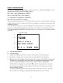
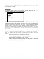
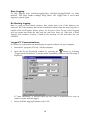
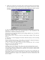
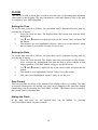
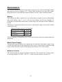
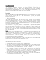
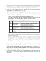
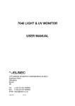
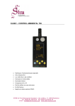
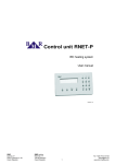
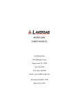
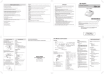
764 ENVIRONMENTAL MONITOR
USER MANUAL
LITTLEMORE SCIENTIFIC ENGINEERING (ELSEC)
Gutchpool Farm
Gillingham
Dorset
UK
Tel:
(+44) (0)1747 835550
Fax: (+44) (0)1747 835552
Email: [email protected]
764.DOC
V3.704
CONTENTS
INTRODUCTION ............................................................................................... 1
BASIC OPERATION ......................................................................................... 2
Set Button...................................................................................................... 3
UNITS OF MEASUREMENT............................................................................. 4
Ultra-Violet (UV) ............................................................................................ 4
Visible Light ................................................................................................... 5
Temperature .................................................................................................. 6
Humidity ........................................................................................................ 6
MAXIMUM AND MINIMUM ............................................................................... 7
DISPLAY ........................................................................................................... 8
Contrast ......................................................................................................... 8
Backlight ........................................................................................................ 8
DATA LOGGING ............................................................................................... 9
Wrap Data ..................................................................................................... 9
Show Status .................................................................................................. 9
Start Logging ................................................................................................. 9
Stop Logging ............................................................................................... 10
Re-Starting logging...................................................................................... 10
Logger-PC Communications ....................................................................... 10
Installing the Software ................................................................................. 13
Viewing the Results using RView ................................................................ 14
Data File Format.......................................................................................... 15
CLOCK ............................................................................................................ 16
Setting the Time .......................................................................................... 16
Setting the Date ........................................................................................... 16
Date Format ................................................................................................ 16
Hiding the Clock .......................................................................................... 16
MAINTENANCE .............................................................................................. 17
Battery ......................................................................................................... 17
Mains Power Supply.................................................................................... 17
Software Version ......................................................................................... 17
CALIBRATION ................................................................................................ 18
Humidity ...................................................................................................... 18
The Calibration Kit ................................................................................... 18
Temperature ................................................................................................ 20
UV & Visible Light........................................................................................ 21
SERVICE AND SUPPORT.............................................................................. 22
SPECIFICATIONS .......................................................................................... 23
PRINTED 23-Oct-09
INTRODUCTION
One of the primary responsibilities of the custodian of artworks and museum artefacts
is to preserve them for future generations. How they are stored and displayed is
central to this, the 764 Environmental Monitor is an easy to use tool to help in
achieving the safest long term protection.
For many years it has been recognised that one of the major causes of damage to
museum objects and other antiquities is the fading and rotting effect of light on the
object. The most damaging part of the illumination is its ultraviolet (UV) content.
Using the 764 measurements can be taken of the proportion of UV present as
microwatts per lumen (µW/lumen), the total amount of UV as milliwatts per square
meter (mW/M2) and the amount of visible light present (Lux).
Most objects are also sensitive to humidity and temperature. The 764 also measures
humidity as % relative humidity and temperature as °C or °F.
The 764 can be left for extended periods to log the above parameters at a user set
interval (10 seconds to 1 hour). The saved data can then be transferred to a computer
for display, graphing etc.
We always want to improve our products. If you have any suggestions please send
them to us.
1
BASIC OPERATION
To take a reading the appropriate yellow button is pushed depending on the
measurement required and the reading is taken.
UV= Ultra Violet (µW/lumen or mW/M2 )
Vis= Visible light (Lux or Foot-candles)
T= Temperature (Centigrade or Fahrenheit)
RH= Humidity (%Relative Humidity)
The unit automatically turns off 10 seconds after the button is released unless a button
is held down for over 5 seconds, this will cause readings to be taken continuously until
a button is pressed.
If the T and UV buttons are pressed together then all parameters are displayed at the
same time. Hold both the buttons down for over 5 seconds for a continuous readout.
Note that the buttons should be pressed firmly for a second or so to ensure reliable
operation.
A
A:
B:
C:
D:
Typical display:
Lux
B
1234
C
D
Min: 1.2 21-08:14
Max: 3456 14-09:34
E
B
H
L
3/11/06
10:20
Units of measurement
Current reading
Minimum reading since last reset, day of month and time of minimum
Maximum reading since last reset, day of month and time of maximum
E: H shows that the reading is “held” and the unit will turn itself off after 10 seconds
of inactivity. A round blob shows the unit is in continuous reading mode until a
button is pushed, nothing here means that a single reading is being taken.
The L indicates logging is in operation, W is shown if logged data is wrapped.
The current time and date are also shown. Unless they are hidden by pressing
Set\Clock\Hide-Unhide.
If a battery symbol appears at B it means that the batteries need to be replaced.
Min & Max are reset by pressing Set\Max-Min\Reset (Press Set 3 times)
2
The above format is slightly different for some parameters and can be altered by the
user if required, see below.
Set Button
The blue Set button is used to access advanced functions, change units etc. If it is
pushed once a menu similar to that below is shown:
Max-Min>
Display>
Units>
Clock>
Calibrate>
The first menu item “Max-Min” is highlighted, different menu items can be
highlighted using the é and ê buttons. The wanted action is done by highlighting the
appropriate menu item and pressing the Set button. To abort without doing anything
press the X button. In some cases a further sub-menu is displayed with more choices.
Elsewhere in this manual directions in the form Set\item1\item2 are given. This means
Press Set, select item1 in the first menu, press Set again, select item2 in the next menu
and press Set.
To take a measurement without having to look at the display while the reading is
taken (for example where the operators head may effect the reading) proceed as
follows:
1. Position the monitor where the reading is to be taken.
2. Push the appropriate button for 1-2 seconds and release.
3. Hold the monitor in position for at least 2 seconds.
1. Without operating any buttons by mistake move the monitor so the reading
can be noted before it turns itself off.
3
UNITS OF MEASUREMENT
Ultra-Violet (UV)
Traditionally UV has been measured in museums as the proportion of ultraviolet
present. This result is useful for checking a particular lamp or window because the
proportion of UV does not change with the distance from the light source. Using a
simple rule the amount of UV on an object can be limited. It is usual to arrange that
the proportion of UV should not exceed 75µW/lumen in museums and galleries,
though some organisations try to keep UV levels below 25µW/lumen
The damage is done by the total amount of UV falling on the object so it is useful to
be able to measure this directly, especially if non standard amounts of illumination are
required. The amount of UV should be as little as possible but in general should not
exceed 20mW/M2, again some organisations keep the level below 6mW/M2.
Both the above units are displayed when the UV button is pressed, one in large
characters, the other smaller at the bottom of the screen. Which is displayed where can
be swapped by pressing Set\Units\µW/Lumn-mW/M².
When measuring low levels of UV the 764 can take up to 5 seconds to take the
reading. So, to get a reasonably quick response, when initially turned on, the unit only
measures for one second and if UV levels are low this will show as zero. If the "UV"
button is pushed again the full 5 seconds is allowed for the measurement and if a low
level of UV is present it will be detected and displayed.
4
Visible Light
This can be displayed either in Lux or Foot-candles. To change the units press
Set\Units\Lux-Footcandl.
A visible light readout is provided to control illumination and limit damage done by
visible light. Normal museum light levels should be limited to 150-250 Lux.
Once measurements have been made the light level can be altered if necessary and UV
filters can be fitted on windows, fluorescent tubes or other UV producing light sources
as required. These filters often deteriorate over a period of years so it is essential to recheck them periodically.
Magazine reprints on the subject of museum lighting , UV etc can be obtained from
the manufacturer.
Suggested light levels for various other purposes are given below:
Corridor, stairs etc
100/150 Lux
Warehouses, storage bays
100/150 Lux
General office work
300/500 Lux
Rough bench/machine work
300/500 Lux
Medium bench/machine work 500/700 Lux
Drawing offices
750/1000 lux
Fine bench work
1000/1500 Lux
Fine inspection
1500/3000 Lux
Minute work
3000/5000 Lux
5
Temperature
Temperature can be measured in degrees Centigrade or Fahrenheit. To change the
units press Set\Units\°C-°F.
Humidity
Humidity is measured as % relative humidity (%RH). This is the fraction of the
maximum amount of water that the air can hold at the current temperature and
pressure.
In general if the temperature is reduced the amount of water it can hold gets less. So if
the temperature of some air is reduced its humidity rises, and at some point the air will
not be able to hold the water it has and water will start to condense out (form
mist/cloud or drops of water on a surface), the relative humidity has reached 100%.
The temperature at which this happens is the dewpoint. The 764 displays the dewpoint
with the humidity and with the temperature.
The temperature/dewpoint difference is often used as a measure of the likelihood of
condensation (fog) occurring, particularly in meteorology. If the temperature is only
one or two degrees above the dewpoint in the evening then fog is likely as the
temperature falls during the night.
The UK National Trust tries to keep the indoor relative humidity between 50% and
65%, aiming for 58%.
6
MAXIMUM AND MINIMUM
The maximum and minimum values for each unit are displayed along with the day of
the month and time the maximum or minimum occurred.
The values can be reset by pressing Set\Max-Min\Reset (This equates to pressing Set
3 times).
To find the date when maxima & minima occurred press Set\Max-Min\Date or Time,
repeat to display the times again.
The maximum and minimum values are also set when data logging is active.
7
DISPLAY
Contrast
The display contrast can be increased/decreased by pressing Set\Display\Contrast UP
or DOWN. If this is done the menu continues to be displayed and the set button can be
pressed repeatedly until the required contrast is achieved.
Backlight
The display backlight operation can be adjusted from the Set\Display menu as
follows:
Menu item
Lamp off
Lamp mostly off
Lamp mostly on
Lamp on
Action
Backlight always off
Backlight initially off, turns on if visible light is less
than 10 Lux
Backlight is initially on, turns off if visible light is more
than 10 Lux
Backlight always on
The backlight uses a considerable amount of power, the more it is used the less time
the batteries will last.
8
DATA LOGGING
Data logging is an optional extra. A standard unit can be upgraded to include data
logging by returning it to the manufacturer. If data logging is not fitted then the
relevant menu items are not displayed.
If data logging is fitted “Data logging” is one of the options when the Set button is
pushed.
Wrap Data
If Wrap is set (press Set\Data logging\Wrap) then logging continues when the logger
memory is full overwriting the oldest data.
If No wrap is selected (press Set\Data logging\No wrap) logging stops when the
memory is full.
Show Status
To see how much data has been saved, when logging was started etc select
Set\Data logging\Show status and the information is shown on the screen for 20
seconds. Press the X button to clear the screen sooner.
Start Logging
To start logging press Set\Data logging\Start and then select the log period and press
Set again.
If logging is started then any previously logged data is lost, so be sure that saved data
has been transferred before starting again.
The Log Period is how often readings are taken, if the log period is short then it will
be less time until memory space runs out. The storage capacity is 10,900 readings of
all 4 parameters (UV, Visible light, temperature and humidity). The other values
(e.g. dewpoint and µW/Lumen) are calculated from the 4 saved parameters.
Logging commences at a time so that measurements are taken at the start of each
minute, 10 minutes, hour etc.
Log Period
10 seconds
1 Minute
10 Minutes
1 Hour
Max Log time (Days, Hours:Mins)
1, 6:16
7, 13:40
75, 16:40 (about 2 ½ months)
454, 4:00 (about 1 year 3 months)
Logging Commences
Start of next minute
Start of next minute
Next whole 10 minutes
past the hour
Start of next hour
Logging will continue until the memory is full or a low battery condition is detected.
9
Stop Logging
To stop logging press Set\Data logging\Stop (Set\Data logging\Disable on older
models). This stops further readings being taken. The logged data is saved until
logging is started again.
Re-Starting logging
Data is saved in non-volatile memory that retains data even if the batteries are
removed. BUT the memory that retains information about when the next log time is
and the clock itself require battery power. So if power is lost for any reason logging
will not restart until both the time and the date have been set. After this is done
logging will continue, leaving a blank in the memory for the data that was not
recorded.
Logger-PC Communications
See below for information on installing the reception software on your computer..
1.
Start the PC program (‘RView’) on the computer.
2.
Open the Set & Download window by pressing the
button or selecting
"Logger/Set & Download" from the menu. Something similar to the following is
displayed:
If "Auto Download" is checked then any new data is downloaded as soon as
contact is made with the logger.
3.
Select Set\Data logging\Transmit on the 764.
10
4. Within 10 seconds place the monitor with it’s black end window (the end with the
RH and temperature sensor) facing directly at the computer's infrared port, within
30-60cm (1-2 feet). When contact is made with the logger the computer requests
the logger status and something similar to the following is shown:
If "Auto Download" was checked then any new data is downloaded automatically.
Otherwise, if required, click on the Download button to start transmission. The
infrared link is closed after all data has been sent.
Information on any logged data and the current readings (updated every 5 seconds) are
shown under "Logger Status".
The Get button can be clicked to check the current logger settings (Clock, log start
time etc).
If "Wrap data" is checked logging will continue when the memory is full overwriting
the oldest data.
If Sync is checked then the logger clock will be set from the PC when the Set button is
clicked. Otherwise it can be set using the 764 Clock controls.
If "Now" is checked the logger will start as soon as possible after "Set" is clicked,
otherwise any start time and date can be set.
"Trigger" is not used by the 764.
The logger name can be changed. This effects where the downloaded data is stored.
The Set button sends the settings on the PC (Logger Clock, start time, interval, name
etc) to the logger. This also terminates the connection. The Set button is enabled when
a valid log interval is chosen.
The infrared link can be closed by pressing the 'X' key on the 764 or closing the "Set
& Download" window on the PC. If the 764 is just taken away without the link being
officially terminated the computer will complain that it has lost communication, this
does not matter.
11
Notes:
• If there are problems with infrared communication in they can sometimes be
solved by selecting “File” and “Options” in RView and setting the Infrared Mode
to “Socket” and clicking on OK.
• After the link is established (“Connected” is shown on the 764 and the PC), if
transmission is interrupted (e.g. by blocking the path between the 764 and the
computer infrared receiver) transmission will re-start from where it left off only if
communication is re-established within 15 seconds. If communication is blocked
for longer than this then the link is broken and the process must be re-started from
step 1. If all the data is not transferred for any reason the procedure can easily be
repeated, though see the information on file names above.
• If power has been lost then the 764 may forget how many records it has saved and
no data will be transferred. It is possible to force the 764 to transmit data by
selecting “File\Get Data” from RView, the user then has to specify how many
records are required and they are transmitted whether they are valid or not.
• If battery power gets low during transmission a warning message is displayed but
transmission continues for as long as possible but may not complete. If this
happens the battery should be replaced and the data retrieved using the method
described in the paragraph above.
12
Installing the Software
Install the PC Infrared Adaptor as instructed in your adaptor’s user manual. Some
adaptors can simply be plugged in and are automatically recognised by Microsoft
Windows. Others require software to be installed BEFORE they are plugged in.
Test the infrared adaptor: Aim the 764 at the computer IR port and select SET\Data
Logging\Transmit. After a few seconds the 764 should recognise the presence of the
PC and display the PC name (No data will be transmitted unless the RView program
is running). If this does not happen further investigation of the computer’s infrared
installation is required.
To install the RView software run the installation program that is provided on a floppy
disc or that has been downloaded from our web site (www.elsec.co.uk) and follow the
instructions given. The installation file is called Rview21.exe or similar.
At the time of writing Rview has been tested with Microsoft Windows 95, 98, NT,
2000 and XP.
Some early versions of Windows 95 have no infrared drivers or unreliable ones.
Infrared version 2.0 or higher should be installed. Windows 98, 2000 and XP infrared
drivers work well.
RView version 3.8 will work with Windows Vista but the installer is not Vista
compatible. To install manually proceed as follows (only do this for Windows Vista
and if you understand computers – if you don’t then get assistance):
1. Rename the installer file RView38.exe to RView38.zip
2. Create a folder “C:\Program Files\ELSEC\RView” or similar.
3. Open the RView.zip file by clicking on it.
4. Drag the files RVIEW.EXE and RVIEW.HLP from RView38.zip to the newly
created folder. Ignore any other files in RView38.zip
5. Create a shortcut to the new copy of RVIEW.EXE (one way is to right click on
it and select “send to” and “desktop”).
6. Drag the shortcut to the start menu.
13
Viewing the Results using RView
For more detailed information on RView see the help file.
When RView is started an empty window is shown. One or more data files can be
opened by selecting File\Open on the menu or pressing the appropriate button on the
toolbar.
When a data file is opened the information is displayed as a graph in it’s own window.
More than one graph can be open at any time.
The graph can then be manipulated in the following ways:
Change the graphed parameters. If ‘Show’ is selected on the menu a list of
parameters that can be plotted is shown with the current selection ticked. The various
items can be ticked/unticked to change what is shown.
Make the graph bigger/smaller. Use the standard window controls on the top right
of the graph window and/or drag the edges of the graph as required.
Zoom to see part of the data in more detail. Move the mouse cursor to one corner
of the area of interest, click and hold the left mouse button while moving the mouse
cursor so that the area of interest has a box drawn round it. When the mouse button is
released the graph is redrawn showing only the selected area.
Change the temperature units. Select ‘Show’ on the menu and the current units are
shown (°C or °F) click on this to change the units.
Move the Legend. When the graph is first drawn the legend box may hide part of the
data. This can be moved by clicking on the box and dragging it to a new location. If it
changes to a free floating window it can be removed completely or put back on the
graph by clicking on it again.
Check the time/value of a point on the graph. Move the mouse cursor to the point
of interest, the time and value represented by the position is shown on a status bar at
the bottom of the window.
Add/Change the title of the graph. Press the Titles button on the toolbar and enter
the title as required.
Print the graph. Select File/Print on the menu.
Copy the Graph to the Clipboard. Select edit/copy on the menu or press the
appropriate button on the toolbar. The saved image can now be pasted into other
programs, documents etc.
14
Data File Format
This information is included for those who want to process logged data using
applications other than RView.
RView saves the data downloaded from the logger as a CSV file (comma separated
variable). This is a plain, human readable text file, each record of Lux, UV,
temperature and RH is on one line, each value separated by a “,”.
The first line has column titles separated by commas and a fifth value giving
information about the log start tome, period etc. This data will look similar to:
2008-10-12_1308_000010_0010901*AName****0000544771
YYYY-MM-DD_HHmm_hhmmss_rrrrrrr*NNNNNNNN*ssssssssss
YYYY-MM-DD = Log start date
HHmm = Log start time (hours and minutes, seconds always zero)
hhmmss = Log interval (hh=hours, mm=minutes, ss=seconds)
rrrrrrr = no of records in file
NNNNNNNN = Logger name, with extra * to make 8 characters
ssssssssss = Misc logger status values
15
CLOCK
The 764 has a built in clock, this is used to show the time of maximum and minimum
values and for data logging. The date functions are valid until January 2098 so the unit
is completely year 2000 compliant.
Setting the Time
To set the time proceed as follows, the procedure can be abandoned at any time by
pressing the X button:
1.
Press Set\Clock\Set time. The display shows the current time with the hours
highlighted.
2.
Use é and ê buttons to adjust the hours to the correct value and press the
Set button.
3.
The minutes are now highlighted. Repeat 2 above to set the minutes, when
the set button is pressed the seconds are set to zero.
Setting the Date
To set the date proceed as follows, the procedure can be abandoned at any time by
pressing the X button:
1.
Press Set\Clock\Set date. The display shows the current date as Day-MonthYear with the day highlighted (note that the date is always shown in this
order regardless of the date format setting as described below).
2.
Use é and ê buttons to adjust the day to the correct value and press the Set
button.
3.
The month is now highlighted. Repeat 2 above to set the month.
4.
The year is now highlighted, repeat 2 above to set the year.
Date Format
The time and date are shown at the bottom of the display with every reading. The date
is normally displayed as day-month-year, this can be changed to the American format
(month-day-year) by pressing Set\Clock\DMY or MDY. The format can be restored to
day-month-year by repeating this.
Hiding the Clock
If the date and time are not needed they can be hidden by pressing
Set\Clock\Hide-Unhide. Repeat to unhide.
16
MAINTENANCE
The sensor windows should be kept clean and grease free. Grease and finger marks
that look clear may be opaque to UV. Ensure that solvents do not come into contact
with plastic parts, especially the perspex window over the visible (left-hand) sensor.
Battery
The batteries should be replaced as soon as the battery symbol is seen on the bottom
left of the display. Any 1.1 to 2.5 volt AA style battery can be used, though it is
preferable to use alkaline cells because of their longer life and much reduced tendency
to leak.
The battery compartment can be accessed by removing the single screw in the bottom
centre of the case.
Suggested battery types (2 off required):
MANUFACTURER
TYPE
Duracell
MN1500
Ever Ready
LR6B4
Nickel Cadmium rechargeable types can be used but they cannot be charged inside the
instrument.
Mains Power Supply
The optional external mains power supply can be connected to the power input socket
on the right hand side of the instrument. This socket is only fitted if requested with
order because the hole required compromises the moisture seal on the casing.
Software Version
The internal software version is displayed when the 764 is turned on. A typical startup message might be “ELSEC 764 V2.1”, in this case the software version is 2.1
17
CALIBRATION
The calibration information is kept in non-volatile EEPROM. If this fails the
instrument displays “Mem Fail” when turned on and will load default calibration
values and future readings may be 25% in error. If this happens a question mark “?” is
displayed on the top right of the display with suspect readings.
Humidity
Like most other RH sensors the 764 should be checked every 6 months or a year. This
can be done by returning the unit to the manufacturer or by using the optional
humidity calibration kit.
The Calibration Kit
This utilises the fact that some salts provide a constant humidity above a saturated
solution. The humidity sensor is placed in a sealed chamber with a saturated solution
of a salt and is then told to calibrate itself, the 764 then measures the current
temperature and calculates what the humidity should be above that salt, allowing it to
work out the calibration constants.
The kit consists of two sample chambers, a support stand, 2 different salt standards
and some pure water. The calibration salts are Magnesium Chloride (MgCl) and
Sodium Chloride (NaCl), these are not particularly toxic (Sodium Chloride is common
table salt) but normal care should be exercised and they should be kept away from
skin, eyes and mouth.
Notes:
It is important that the procedure is done at a constant temperature so that when the
calibration is done the temperature of the saturated salt is the same as the air above it.
The best place is an underground room, if this is not available use somewhere with a
constant temperature, away from sunlight, heaters, open windows etc. A closed
wooden desk draw or cupboard is quite good.
If Magnesium Chloride is left exposed to the air (ie with the lid off) it will absorb
moisture from the air until it overflows and makes a mess.
The calibration procedure is as follows:
1. Read through the whole procedure before doing anything.
2. Put a level teaspoon of Magnesium Chloride in the bottom of one chamber and the
same amount of Sodium Chloride in the bottom of the other. Be very careful not to
contaminate the two salts with each other. Label the 2 chambers.
3. Put a few drops of the pure water onto the salts to make a paste, there should be
plenty of undisolved salt but none of it should be dry. The level of the paste should
be well below the side hole where the sensor is to be inserted, if any paste gets into
the side hole then clean the chamber in running water, dry and start again.
4. Put both the top and side lids on the chambers and leave them on a level surface in
a constant temperature environment for at least 2 hours.
18
5. Insert the 764 sensor probe into the side hole of the Magnesium Chloride chamber,
push it all the way in. A support stand is provided to place under the 764 so that it
and the sample chamber are level. Be sure not to get any paste on the sensor.
6. Leave for at least 2 hours, preferably overnight, in the constant temperature
environment. The 764 does not have to be on.
7. With the 764 probe still in the calibration chamber:
Press Set\Calibrate\Humidity\MgCl (33%). Sure?? will be displayed, the Set
button must be pressed again within 2 seconds to activate calibration. The display
will show “Working …” followed by either:
“Done” if the 764 has been calibrated before (usually the case)
“Not Done” if this is the first time any humidity calibration has been done on
this instrument. This indicates that the other salt still has to be used.
“xx Fail” Where xx is a code indicating the type of error:
Fail Meaning
Possible causes
code
10 RH for MgCl >
Calibration standards wrong way round,
RH for NaCl
missing or wrongly prepared.
Sensor damaged or disconnected
12 RH difference
Calibration standards wrong way round,
between samples
missing or wrongly prepared.
too small
Sensor damaged or disconnected
Other Calculation
Sensor damaged or disconnected
overflow
Notes:
Even if “Done” is displayed the following steps still have to be performed to
complete the calibration.
If “Fail” is displayed clean out the chambers in running water, dry thoroughly
and do the whole procedure again ignoring any further “Fail” messages until
step 8 below. If step 8 still produces a fail message it indicates that the
humidity sensor is damaged requiring the return of the unit to the manufacturer
for repair.
8. Repeat steps 5, 6 & 7 with the Sodium Chloride chamber, selecting
Set\Calibrate\Humidity\NaCl (75%) in step 7.
NOTE: In later versions of the 764 there are menu options of “35%” and “75%”
that can be used with other calibration standards. Do not use these options with the
ELSEC calibration salts (MgCl and NaCl).
9. If the sample chambers are to be kept charged then put both top and side lids on
and keep on a level surface. Otherwise clean them in running water and dry
thoroughly.
19
Temperature
The 764 is fitted with a solid state temperature sensor that should not normally require
calibration.
The unit can be checked by putting it together with another, known accurate,
temperature measuring device for at least an hour. Make sure that the two sensors are
within 2cm (1") of each other and that neither are close to anything hot or cold,
sunlight etc..
If the units do not agree the 764 can be adjusted by selecting
Set\Calibrate\Temperature, this allows the user to change the temperature offset with
the é and ê buttons before pressing the Set button. Pressing "X" leaves the offset
unchanged.
The offset is the temperature (always in Centigrade) that is added to the measured
temperature.
Example: Correct temperature is 20.4°C, 764 indicates 20.1°C, current offset is -0.2°C
The offset should be changed to +0.1°C
20
UV & Visible Light
The 764 calibration should not drift with time but to be sure of accuracy the
instrument can be returned to the manufacturer for a calibration check every 2-5 years.
The 764 has a very carefully defined frequency response (i.e. which wavelengths of
light it is sensitive to). Other light meters are often more sensitive to infra red light
than they should be and so will give a higher reading with light sources that contain
infrared (e.g. ordinary filament light bulbs).
Because the 764 has a cosine angular response it may give different readings to a type
762 which is relatively directional. In other words the 764 is more sensitive to light
coming at an oblique angle than the 762.
Note that the human eye has a logarithmic response, this means that if two luxmeters
are placed side by side they may give different readings even if it looks like they are
getting a similar amount of light. To compare the readings on 2 meters they each need
to be placed in the exactly same position under exactly the same lighting conditions
with the operator being very careful not to shade the meters differently.
21
SERVICE AND SUPPORT
For support and repairs contact:
Littlemore Scientific Engineering
Gutchpool Farm
Gillingham
Dorset UK
SP8 5QP
Tel: 01747 835550
Fax: 01747 835552
Email: [email protected]
http://www.elsec.co.uk
This equipment complies with EU Directive 2002/96/EC
The symbol of the crossed container on the equipment shows that the product, at the
end of its useful life, must be collected separately from other refuse. When it is
disposed of in the European Union it should be placed with other electronic waste at
the place designated by the waste collection authority.
22
SPECIFICATIONS
Method of radiation detection Twin silicon photodiodes connected to microprocessor.
Visible wavelength range
400-700nM (CIE response). No correction required for different
light sources.
Visible power range
0.1 - 200,000 Lux (0.1 – 20,000 Foot-candles)
UV wavelength range
300-400 nM
UV power range
UV proportion range
RH sensor
RH range
Display resolution
2 - 50,000 mW/M2
0 - 10,000 µW/Lumen
Capacititive film type
0-100%RH
Lux: 0.1 up to 100 then 1
Foot-candles: 0.1 up to 100 then 1
UV: 0.1 up to 100 then 1
Proportion of UV: 1 µW/Lumen
Temperature: 0.1°C or °F
RH: 0.1%
Accuracy
Light: 5% ±1 displayed digit
UV: 15% ±1 displayed digit
Temperature: ±0.5°C (±0.9°F)
RH: ±3.5% 0-90%, otherwise ±5%
Angular response
Readout
Data logging time intervals
(Time till full)
Cosine (Light & UV)
8 line graphical Liquid Crystal Display with automatic backlight
10 seconds (30 hours), 1 minute (7½ days) , 10 minutes (75
days), 1 hour (454 days)
Data logging storage capacity
Computer Interface
Date functions
Batteries
Battery Life
10,900 readings of all 4 parameters
IrDA compatible wireless infra-red link.
Display as day-month-year or month-day-year.
2 off alkaline AA type.
Approx 100 Hours continuous use or 12,000 readings taking 30
seconds each.
Battery life will be less if the display backlight is used
External Power Supply
(If available)
4.0-5.2V DC, 100mA A suitable mains power supply can be
provided as an optional extra (please specify mains voltage
required).
Operating Temperature
Dimensions
0-50°C
150 x 65 x 25mm 5.9 x 2.5 x 1 inches Including
RH/Temperature probe
Weight
165g (5.6 oz) with batteries.
23
24