1
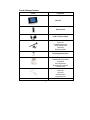
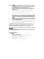
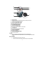
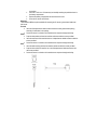
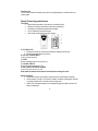
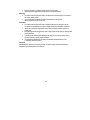
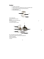
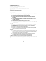
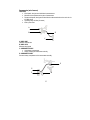
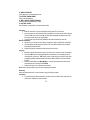
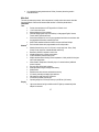
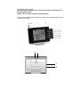
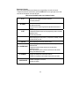
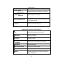
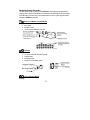
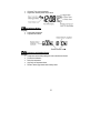
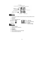
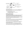
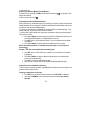
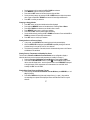
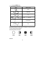
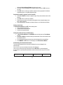
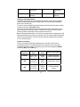
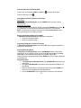
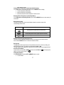
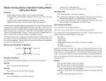
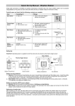
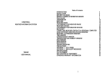
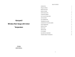
HONEYWELL
PROFESSIONAL WEATHER STATION
WITH REMOTE CONTROL
TE923W
USER MANUAL
Table of Contents
Introduction
Standard Package Contents
Installation
Before you begin
Ultraviolet (UV) Sensor
Remote Thermo-Hygrometer Sensor
Rain Gauge
Anemometer (wind sensor)
Main Unit
Battery installation
Buttons and Controls
Initial Set Up
Backlight
Connecting Weather Station to a Personal Computer
Navigating through the modes
Customizing your Weather Station
Operations and Window Selection
Pressure and Weather Forecast Window
UV Window
Time Window
Manual Settings
Sunrise/Sunset Window
Temperature and Humidity Window
Rain Window
Wind Window
Memory Reset Procedure
Maintenance
Troubleshooting
PRECAUTIONS
Appendix - City Codes
Specifications
FCC STATEMENT
DECLARATION OF CONFORMITY
STANDARD WARRANTY INFORMATION
2
3
4
5
6
6
9
11
13
15
16
18
20
20
20
22
25
25
25
28
29
29
33
35
37
38
40
40
41
41
43
45
47
48
48
Introduction
Thank you for selecting the Honeywell Professional Weather Station with Remote control. This
compact and easy-to-use product features a wide variety of time and weather data, such as
precise atomic time, perpetual calendar, air temperature, relative humidity, barometric pressure,
wind speed and direction, rainfall, UV levels and etc.
In this package you will find:
One Main Unit (receiver) (TE923WD)
One IR Remote Control (TS607)
One Rain Gauge (remote rain sensor/transmitter) (TS906)
One Anemometer (remote wind sensor/transmitter) (TS805)
One UV (ultraviolet) sensor (remote ultraviolet sensor/transmitter) (TS704)
One Five-Channel Temperature & Humidity Sensor (transmitter) (TS34C)
One CD disk with generic PC connection software
One USB cable
One 7.5V AC/DC Adapter
Mounting Hardware with Allen Wrench
One User Manual
Required for installation (not included)
-
Small Phillips screwdriver
-
Anemometer mounting pole
-
Small paper clip to reset sensors
NOTE: If any items are missing or damaged, please contact Hideki Electronics Customer Service
before proceeding with installation.
3
Standard Package Contents
Picture
Components
Main Unit
Remote Control
AC/DC 7.5V power adaptor
UV Sensor consists of:
Sensor Unit
U-Shaped Sensor holder
Circular Ground Stand
Stake Base
Wall-Mounting Base
Thermo Hygrometer Sensor
Rain Gauge consists of:
Funnel shaped top with battery
compartment
Rain Gauge bucket
Bucket see-saw mechanism
Protective screen
Anemometer consists of:
Wind Cups
Wind Vane
Anemometer arm
Anemometer base
PC Software
WeatherCapture CD ROM
4
4 screws for securing rain gauge to the flat surface;
4 screws for securing anemometer to vertical
surface
Mounting hardware
2m (6ft) USB cable
PC connection cable
Installation
The Honeywell Professional Weather Station TE923W operates at 433MHz radio frequency, so no
wire installation is required between the main unit (receiver) and the remote weather sensors
(transmitters).
The remote weather sensors include a thermo-hygrometer (temperature and humidity) sensor, UV
(ultraviolet) sensor, anemometer (wind sensor) and a rain gauge (rain sensor). All data measured
by these remote sensors is transmitted to the main unit wirelessly, with the operating range in the
open area from 100 feet (30 meters) for anemometer and rain gauge; and up to 328 feet (100
meters) for thermo-hygrometer and UV sensors.
Remote UV sensor, anemometer and a rain gauge must be placed outdoors to measure weather
elements.
Remote thermo-hygrometer can be placed indoors or outdoors, depending on the area where the
temperature and humidity are intended to be measured. If you intend measuring outdoor
temperature and humidity, place the remote sensor outdoors.
NOTE: It is critical to assemble and power up all of the remote weather sensors BEFORE setting
up the main unit.
NOTE: It is critical to power up and test communication between all of the weather sensors and the
main unit BEFORE permanently mounting them outside.
5
Before you begin
•
We recommend using alkaline batteries for the remote weather sensors and the main
unit when temperatures are above 32°F (0°C). We recommend using lithium batteries for
the remote weather sensors when temperatures are below 32°F (0°C).
• Avoid using rechargeable batteries. (Rechargeable batteries cannot maintain correct
power requirements).
• ALWAYS install batteries in the remote weather sensors before the main unit.
• Insert batteries before first use, matching the polarity in the battery compartment
• Remove protective plastic screen from LCD display (if any).
• During an initial setup, place the main unit close to the remote weather sensors.
• After reception is established (all of the remote readings will appear on the main unit’s
display), position the remote sensors and the main unit within the effective transmission
range of up to 328 feet (100 meters). Ideally they should be placed within the line of sight
of the main unit. See placement tips in the user manual for each remote weather sensor
separately.
• Transmission range may be affected by trees, metal structures and electronic appliances.
• The main unit must be placed indoors.
• The effective operating range may be influenced by the surrounding building materials
and how the receiver (main unit) and transmitters (weather sensors) are positioned.
• Place the remote weather sensors so that they face the main unit (receiver), minimizing
obstructions such as doors, walls, and furniture.
Note: When the temperature falls below freezing, the batteries in the outdoor remote
weather sensors may have reduced voltage supply and a shorter effective range. We
recommend using lithium batteries at temperatures of 32°F (0°C) and below.
IMPORTANT: Make sure that the remote weather sensors are easily accessible for cleaning and
maintenance.
We recommend cleaning the remote weather sensors periodically, as the dirt and debris
may affect sensors accuracy.
Ultraviolet (UV) Sensor
FEATURES
• Ultraviolet light levels measurement
• Remote UV levels data transmission to the main unit via 433MHz signal
• 328 feet (100 meters) transmission range
• Low battery indicator
• Three different placement options – ground, stake and wall
6
A
B
G
F
C
E
D
A. LED INDICATOR
• Flashes once when the remote sensor transmits a reading to the main unit
• Flashes twice when battery power is low
B. BATTERY COMPARTMENT SCREW
Holds battery compartment door in place
C. U-SHAPED SENSOR HOLDER
Holds UV sensor in upright position
D. CURCULAR GROUND STAND
Secures sensors in the sensor holder on the flat surface
E. UV SENSOR LID
Covers UV sensor and seals battery compartment
F. BATTERY COMPARTMENT
Holds two AA-size batteries
G. BATTERY COMPARTMENT DOOR
Covers two AA-size batteries
Assembly
• Snap the U-shaped sensor holder onto the UV sensor unit side grooves
• Insert the round end of the U-shaped holder into one of the mounting hardware pieces
provided
Battery installation
• Unscrew the lid on top of the UV sensor unit.
• Remove the screw from the battery compartment door with a small Phillips
7
•
screwdriver
Insert two 2 “AA” size 1.5V batteries (not included) matching the polarities shown in
the battery compartment.
Replace the battery compartment door and secure the screw
Screw the UV sensor unit lid back
•
•
Mounting
There are three different options available for mounting the UV sensor: ground stand, stake and
wall mount.
Ground:
• Insert the U-shaped sensor holder round end into the circular ground stand opening,
matching 2 round holes in the opening
• Secure the sensor in a location with a maximum sun exposure throughout the day.
Stake:
• Snap the sharp stake end onto the metal bar and secure with the screws provided.
• Insert the other end of the metal bar into the U-shaped sensor holder and secure with the
screws provided.
• Secure the sensor in a location with a maximum sun exposure throughout the day.
Wall:
• Insert the wall mounting end into the metal bar and secure with the screws provided.
• Snap the other end of the metal bar on to the U-shaped sensor holder and secure with
the screws provided.
• Secure the sensor in a location with a maximum sun exposure throughout the day.
8
Placement tips:
The UV sensor should be mounted in the area free of sunlight shadows or reflections from the
nearby objects.
Remote Thermo-Hygrometer Sensor
FEATURES
• Remote data transmission to the main unit via 433 MHz signal
• 328 feet (100 meters) transmission range without interference
• LCD display of measured temperature and humidity
• Five (5) transmission channels selection
• Case can be wall mounted using built-in hanger
A. LED INDICATOR
• Flashes once when the remote sensor transmits a reading to the main unit.
• Flashes twice when battery power is low.
B. BATTERY COMPARTMENT
Holds two AA-size batteries
C. RESET
Resets all readings (requires small paper clip)
D. CHANNEL SWITCH
Selects the desired channel from 1 to 5
E. WALL-MOUNT RECESSED OPENING
Keeps the remote sensor on the wall
Note: Install the batteries and select the channel before mounting the sensor.
Battery installation
• Remove the screws from the battery compartment with a small Phillips screwdriver.
• Set the channel 1 through 5. The switch is located in the battery compartment. Channel 1
is typically selected if only one remote sensor is being used.
• Install 2 “AA” size alkaline batteries (not included) matching the polarities shown in the
battery compartment.
9
• Replace the battery compartment door and secure the screws.
• Secure the thermo-hygrometer remote sensor in the desired location.
Mounting
• The remote thermo-hygrometer sensor can be placed on the flat surface or mounted on
the wall in vertical position
• Use the wall mount hardware and screws provided when mounting the
thermo-hygrometer sensor on the wall
Placement
• The remote thermo-hygrometer sensor should be placed in the area with a free air
circulation and sheltered from the direct sunlight and an extreme weather conditions.
• Ideally, place the thermo-hygrometer sensor above the natural surfaces (such as a
grassy lawn).
• Avoid placing the thermo-hygrometer sensor near sources of heat such as chimneys and
heating elements.
• Avoid any areas collecting and radiating a heat from the sun, such as metal, brick or
concrete structures, paving, patios and decks.
• The international standard for the valid air temperature measurements is 4 feet
(1.25meters) above the ground.
Operation
Immediately after batteries are correctly installed, the remote sensor will start transmitting a
temperature and humidity data to the main unit.
10
Rain Gauge
FEATURES
• Precipitation measurement
• Remote transmission of the rainfall data to the main unit via 433 MHz signal
• 100 feet (30 meters) transmission range without interference
• Built-in installation level
• Non-corrosive protective screen
B
A
C
A. Rain gauge bucket
Contains mechanical components
B. Knob
Secures the top on the rain gauge bucket
C. Rain gauge bucket feet
Secures the rain gauge on its place
C
G
D
E
H
H
F
I
D. Funnel-shaped top with battery compartment
Contains battery compartment and rainfall counting electronics
E. Battery compartment
Holds two AA-size batteries
F. Screws
11
Secure battery compartment cover
G. Built-in level with bubble
Ensures level rain gauge mounting for proper operation
H. Bucket see-saw mechanism
Collects the rainfall in one of its containers and self-empties once full
I. Protective screen
Protects the rain gauge funnel from debris
Battery installation
• Unlock the funnel-shaped top on the rain gauge by turning both knobs on the sides in an
anti-clockwise direction.
• Remove the funnel-shaped top lifting it off the rain gauge bucket.
• Remove 7 small screws from the battery compartment cover using a small Phillips
screwdriver
• Insert 2 “AA” size alkaline batteries (not included), matching the polarities as shown in
the battery compartment.
• Replace the battery compartment door and secure the screws.
• Insert the funnel-shaped top into the rain gauge bucket and secure it into place by turning
the knobs clockwise.
Mounting
• Make sure that the rain gauge bucket is level – check if the bubble center is inside the
built-in leveler.
• Place the protective screen over the top to protect the rain gauge from the debris.
• Mount the rain gauge in place using mounting hardware.
• Make sure that the rain gauge is in open area where precipitation falls directly into the
gauge’s bucket, ideally 2-3 feet above the ground.
Placement
• The rain gauge should be placed in an open area away from the walls, fences, trees and
other coverings which may reduce the amount of rain falling into the bucket. Additionally,
trees and rooftops may be sources of pollen and debris.
• To avoid the rain shadow effects, place the rain gauge horizontally, on the distance
corresponding to two to four times the height of any nearby obstruction.
• It is important that excess rain can flow freely away from the rain gauge.
Operation
After batteries are correctly installed, the rain gauge will start transmitting a rainfall data to the main
unit.
12
Anemometer (wind sensor)
FEATURES
• Wind speed, wind gust and wind direction measurement
• Measures the temperature at the place of anemometer
• Remote wind speed, wind gust and wind direction data transmission to the main unit via
433 MHz signal
• Operating range 100 feet (30 meters)
• Wall or pole mount
A
B
D
C
A. WIND VANE
Indicates wind direction
B. WIND CUPS
Measures wind speed
C. ANEMOMETER BASE
• Holds battery compartment
• Allows mounting the anemometer vertically
D. ANEMOMETER ARM
Connects battery compartment to the anemometer assembly
E
G
F
H
13
E. WIND CUPS SHAFT
Holds wind cups on the anemometer arm
F. BATTERY COMPARTMENT
Holds 2 AA-size batteries
G. WALL MOUNT SCREW OPENINGS
Allows securing the anemometer in place
H. BATTERY COVER
Secures battery compartment on the anemometer base
Assembly
• Slide the wind cups on to the anemometer rotating shaft. Do not use force.
• Insert the longer arm of the Allen Wrench (provided) into the wind cup set screw opening.
Feel the head of the set screw inside the wind cups and tighten carefully the set screw
securing the wind cups to the rotating shaft.
• Test to ensure cups are securely fastened to the shaft and cannot be removed
Battery installation
• Remove four (4) screws from the battery compartment with a small Phillips screwdriver.
• Open the battery compartment and install 2 “AA” size alkaline batteries (not included)
matching the polarities shown.
• Replace the battery compartment door and secure the screws.
Aligning
• Manually point the wind direction vane to the north (use a compass or map if necessary).
• Press the “SET” button located inside battery compartment (on the shorter side of the
rectangle) with a paper clip. “SET” button selects a new direction for NORTH and, when
pressed repeatedly, alternates between the factory default NORTH and user selected
NORTH.
• Watch the main display unit Wind Window – the next data transmission will show the
wind direction arrow pointing to the NORTH
• Replace the battery cover and secure the screws
Note: Repeat this procedure every time when changing the batteries.
Mounting
Mount the anemometer onto a vertical surface, using the fittings provided.
Placement
• The anemometer should be mounted in an open area with a free air flow; away from the
nearby trees, buildings or other structures
14
•
It is suggested mounting anemometer at 33 feet (10meters) above the ground in
unobstructed area
Main Unit
The main unit measures pressure, indoor temperature, humidity, and receives atomic time data
from the US Atomic Clock and all remote weather sensors. It should be placed indoors.
FEATURES
Time
• Precise time and date set via RF signals from US Atomic clock
• 12 or 24 hour time format
• Manual adjustment of time and date
• Calendar displaying date with month and day in 6 languages English, German,
French, Italian, Spanish and Dutch
• Sunrise/set calculation for over 100 pre-programmed world cities in accordance with
the geographical information entered by the user
• Moon Phase calendar and historical data for the past and future 39 days
• Dual crescendo alarms with programmable snooze and pre-alarm
Weather
• Weather forecast for the next 12 to 24 hour in seven large icons: Sunny, Partly
Cloudy, Cloudy, Light Rain, Unstable Weather and Snowy
• Barometric pressure in imperial or metric units
• Altitude adjustment for pressure compensation
• 24 hour barometric pressure history chart
• Multiple weather alarms including Hi/Low temperature, Hi daily rainfall, Hi wind gust
and Hi wind speed alerts
• Indoor/Outdoor Temperature & Humidity in up to 5 remote locations (additional
sensors required)
• Dew point and comfort level indicators
• Wind speed and wind gust averages and memory
• Wind direction
• Rainfall amount with minimum and maximum memory
• UV intensity with daily and weekly highs and lows
• 200 weather records without PC connection
• PC software (included) and USB port
• Operating range from 100 feet (30 meters) up to 328 feet (100 meters)
Display
• Light sensor detects low light conditions and LCD lights up automatically when
adapter is connected
15
•
Infrared remote control of all display functions
Power
• AC/DC adapter for automatic remote control
• 4 AA batteries
Battery installation
• Open the battery compartment door on the back of the main unit.
• Insert four (4) AA size batteries according to the polarities shown and replace the battery
compartment door.
• Connect 7.5 V AC/DC adapter provided to the main display unit and plug into to the wall
power outlet.
Note: The AC/DC adapter connection is required for automatic backlight control and a
handheld remote control functions. If the main unit operates solely on the battery
power, the auto backlight control and handheld remote control functions will be
disabled.
• When placing the main unit on the table or other horizontal surface, unfold the table
stand adjusting it to the desired viewing angle.
• When mounting the main unit on the wall or vertical surface, fold the table stand back
into the unit and use the mounting hardware provided.
Placement
• Make sure that the main unit is locating within the operating range of all remote weather
sensors.
• Ideally the remote weather sensors should be mounted within the line of sight of the main
unit.
• Transmission range may be affected by trees, metal structures and electronic appliances.
• Test reception before permanently mounting all the remote weather sensors.
Avoid placing the main unit in the following areas:
• Direct sunlight and surfaces emitting and radiating heat, such as heating ducts or air
conditioners.
• Areas with interference from the wireless devices (such as cordless phones, radio
headsets, baby listening devices) and electronic appliances.
Operation
Once the main unit is powered, the display will show all available LCD segments for 2 seconds.
IMPORTANT: All of the display functions will be locked, allowing setting your local altitude and
pressure parameters .The locked display will show the pressure icon and abbreviation “inHg”
flashing in Pressure Window, indoor temperature and humidity readings in
Temperature/Humidity Window, default time in Time Window and a default sunset/sunrise time
in the Sunrise/Sunset Window.
If pressure and altitude are not configured during this time, the Weather Station will self-calibrate in
a few minutes and show the default settings for the pressure and altitude (sea level) and then all
16
remote weather sensors readings.
NOTE: When adjusting altitude in feet or meters, be noted that the last small digit is not a
decimal but a whole number.
Example: “350” feet means 350 feet (three hundred fifty feet).
To set the pressure & altitude units and program your altitude, use the handheld remote control or
the main unit control panel
G
H
J
I
K
L
N
M
17
Buttons and Controls
Most of the handheld remote control buttons are corresponding to the main unit controls.
To expose the main unit control buttons, press the OPEN button on the upper right corner of the
main unit and the controls’ cover door will open.
Main unit and handheld remote control adequate buttons
A. UP
B. DOWN
C. SET
-Selects the next available mode anti-clockwise
-Increases parameters
-Selects the next available mode clockwise
-Decreases parameters
-Recalls all remote sensors signals when depressed and held for 5
seconds
-Rotates display for current mode
-If depressed and held, enters into the programming mode or changes
parameter’s units
-Confirms set parameters
D. MEMORY
-Allows displaying the moon phase, UV, temperature, humidity, rainfall
and wind memory records
E. HISTORY
-Allows displaying the sea-level pressure history
F,G. ALARM/CHART
H. CHANNEL
I. LIGHT/SNOOZE
-Allows displaying the time alarms and alerts for the temperature,
rainfall and wind.
-If depressed and held, allows entering into the alarm/alert
programming mode
-When depressed and hold in pressure and forecast mode, allows
viewing of the different bar charts
-Changes the temperature and humidity channel
-Enables the temperature and humidity channel auto-scan mode
-Enables a backlight for 5 seconds
-Snoozes the alarms
18
Main unit only
J. OPEN
-Opens the control buttons panel on main unit
K. LIGHT SENSOR
– AUTO, ON, OFF
-Toggles the light sensor to automatic, on or off setting
L. SENSITIVITY
– HIGH/LOW
-Adjusts the light sensor sensitivity
M. AC/ DC ADAPTOR INPUT
- Connects main unit to the power outlet through the AC to
7.5V DC adapter provided
N. USB Port
- USB Port provides PC connectivity
Handheld remote control only TS607 (Selections)
Temperature & Humidity
Button
-Selects the Temperature and Humidity Mode
Wind Button
-Selects the Wind Mode
UV Button
-Selects the UV Mode
Pressure & Weather
Forecast Button
-Selects the Pressure and Weather Forecast Mode
Rain Button
-Selects the Rain Mode
Sunrise/Sunset Button
-Selects the Sunrise/Sunset Mode
Clock and Alarm Button
-Selects the Clock and Alarm Mode
Button
-Selects 24 hours History Chart
-Alternates between Pressure, Channel1 Temperature or
Channel One Humidity
19
Initial Set Up
• Power up each of the remotes as instructed in previous sections
• Then power up the main display.
• Once the main unit is powered, the display will briefly show all available LCD segments
for a moment.
• IMPORTANT: Do not press any buttons during the set up process which typically takes
about 5-10 minutes.
The display functions will be automatically set including local altitude and pressure parameters.
The display will show the pressure icon
and “inHg” (inches of Mercury) flashing. You will
know that the unit is finished self-adjustment when the display shows the default settings for the
pressure and altitude (sea level) indoor/outdoor temperature and humidity readings, remote
sensors readings, etc.
Many settings can be changed or customized to your preference, after the display has stabilized
• The pressure parameters during Initial Setup (See Pressure and Weather Forecast
Window)
• The time, the date and the weekday language (Clock and Alarm Window)
• The location data will determine the time zone and sunrise and sunset times (Sunrise&
Sunset Window)
IMPORTANT: If after the initial setup, the altitude or other parameters are not displayed, or dotted
lines are displayed, for example (-.- -) you may have to restart the main unit to reset it.
Note: It is a normal unit operation that history chart is constantly moving on the main unit display
Backlight
The main unit backlight can be turned on, off or automatically toggled depending on the
environment light conditions. Use the light sensor switch at the back of the main unit to select a
desired backlight setting.
For the automatic backlight control, the sensitivity of the light sensor can be adjusted to high or low
using the switch, located on the back panel.
NOTE: For an automatic control function the main unit must be plugged into the wall power outlet
via the AC/DC adaptor provided.
Connecting Weather Station to a Personal Computer
To collect and manipulate data from your weather station you may connect the main unit to the
computer via USB cable.
Proceed in the following order:
• Make sure all sensors have batteries installed and the main unit is plugged in to the wall
power outlet through the AC/DC adapter provided
20
•
Insert the CD-ROM into available drive and install the software following instructions of
the installation wizard.
• Connect the main unit to the computer USB port using the USB cable provided.
• Open installed software package: double-click the icon on the computer desktop
You may customize software screen by selecting the weather parameters to be displayed, units for
these weather parameters, location and other user-definable elements.
When determining data transfer interval from the main unit to your computer consider the time duration
for each data point. For example if you select 5 minutes, each point on the graph will be placed every
5 minutes. If you will select 3 hours, then the graph trend will take at least 24 hours to show 8 data
points.
You can use Print Screen option to create pictures and send them by E-Mail and use them on your
website
If you want to use collected weather data in other applications, the software allows storing data on
your computer hard drive in text file called RECORDS.txt. This file can be exported to Excel. This file
location is: C:/Program Files/WeatherCapture.
NOTE: Check our website www.honeywellweatherstations.com periodically for useful tips and the
latest software versions
21
Navigating through the modes
The main unit has seven (7) different modes (Windows) each displaying the separate data
category. When a specific mode (Window) is selected the corresponding icon will start flashing.
Press UP button on the main unit or the handheld remote control to cycle through the modes
clockwise or DOWN anti-clockwise.
Pressure and Weather Forecast Window
Displays:
• Moon phase
• Weather forecast
• Current pressure and history bar chart
UV Window
Displays:
• UV index or Minimum Ultraviolet Exposure
• Daily Maximum
• Weekly Maximum
• Remote UV sensor battery status
Clock and Alarms Window
Displays:
22
•
•
US Atomic Time clock and calendar
Single alarm, weekday alarm and pre-alarm
Sunrise/Sunset Window
Displays:
• Sunrise and sunset times
• Longitude and Latitude
Temperature and Humidity Window
Displays:
• Temperature and humidity readings for indoor and selected channel
• Comfort level indication
• Dew point temperature
• High and Low temperature alerts
• Remote Thermo-Hygrometer sensor battery status
23
Rain Window
Displays:
• Current amount of precipitation as well as for the last hour, last day, yesterday, last week
and last month
• Rainfall alert
• Remote rain gauge battery status
Wind Window
Displays:
• Wind Chill temperature
• Temperature at place of anemometer
• Wind direction
• Wind speed
• Wind gust speed
• Alert for programmed wind speed and wind gust
• Remote anemometer battery status
24
Customizing your Weather Station
To use your station, you will have to complete the steps identified under INITIAL SETUP while this
section of the manual will provide you with additional operational details and suggestions for
custom settings and alarms including:
• The time alarms (Clock and Alarm Window)
• The temperature alerts (Temperature and Humidity Window)
• Daily rainfall alerts (Rain Window)
Operations and Window Selection
Pressure and Weather Forecast Window
Your weather station is designed to display (local) barometric pressure, sea level pressure, weather
forecast and moon phases. Historical statistics can also be viewed, including the sea-level
pressure for the past 24 hours, moon phase for the past and following 39 days, and a selectable
bar-chart for viewing pressure/ temperature & humidity history. Pressure is displayed inHg (English),
hPa/mBar (scientific) or mmHg (metric). Altitude is displayed in meters or feet.
The weather station is designed to measure local pressure and calculate the other two parameters
based on the Local Pressure.
Sea Level Pressure and Altitude are interdependent. If you adjust altitude, it will calculate sea level
pressure, if you adjust sea level pressure, it will automatically calculate altitude. You can only
adjust one of the two – either sea level barometric pressure or altitude.
If you wish to know pressure changes at your specific location (house), the LOCAL barometric
pressure should be selected In this case, the local altitude/elevation must be programmed
according to GPS readings, Internet, etc.
If you wish to know pressure changes in your surrounding metro area, then SEA LEVEL
barometric pressure option should be selected. In this case, the SEA LEVEL barometric pressure
value can be adjusted according to the local metro area weather information. (Sources – local TV
25
or radio station, etc).
Accessing Pressure and Weather Forecast Window
From the main unit: Press UP or DOWN until the weather forecast icon
display starts flashing.
From the remote control: Press .
on the upper left of the
Programming Pressure & Altitude Parameters
During initial power up, the weather station won’t operate (first 2 minutes), until the pressure and/or
altitude parameters are not configured. The Pressure and Weather Forecast Window will show the
pressure icon and abbreviation “inHg” flashing.
If no values are entered within first 2 minutes the unit will self-adjust to the default settings – inHg
(inches of Mercury) for pressure units and 33 feet for altitude.
To set the pressure and/or altitude units and program the altitude or adjust the sea level pressure
during these 2 minutes:
• Press UP or DOWN arrow button selecting the pressure in inHg(inches of mercury), hPa
(hectoPaskal)/mBar(millibars) or mmHg(millimeters of mercury)
• Press SET button to confirm and store selection. Then unit will advance to the altitude
unit selection
• Press UP or DOWN arrow button selecting the altitude unit in feet or meters.
NOTE: When adjusting altitude, be noted that the last small digit is not a decimal but a
whole number.
Example: “350” feet means 350 feet (three hundred fifty feet).
•
•
•
•
Press SET button to confirm and store your selection. Unit will advance to the altitude
programming
Press UP or DOWN arrow button to adjust the altitude value. Press and hold either
button for the advanced setting.
Press SET to confirm the selected altitude value.
Wait for about 15 seconds until unit will calculate and display adjusted pressure
Viewing the Pressure and Altitude Information
To view a pressure or altitude information, press SET button selecting the sea level pressure, local
pressure and local altitude screens.
Changing or Setting Sea Level Pressure
• Press SET button until the local pressure with the word “SEA LEVEL” is displayed.
• Press and hold MEMORY button until the pressure unit is flashing, inHg, mmHg or
hPa/mBar
26
•
•
•
•
•
Set the pressure units by pressing the UP or DOWN arrow buttons
Press MEMORY button to confirm your selection
Press and hold SET button until the local pressure digits will flash.
Set the sea level pressure by pressing the UP or DOWN buttons to adjust the pressure
value. Press and hold UP or DOWN arrow buttons for faster digits advancement
Press SET to confirm your selection.
Changing or Setting Altitude
• Press SET button until the local altitude value will be displayed
• Press and hold MEMORY button until the altitude unit is flashing, Feet or Meters.
• Press UP or DOWN arrow buttons to set altitude in feet or meters
• Press MEMORY button once to confirm your selection
• Press and hold SET until the pressure digits are flashing.
• Set the altitude value by pressing the UP or DOWN arrow buttons. Press and hold UP or
DOWN arrow button for faster digits advancement
• Press SET button to confirm your selection.
Viewing the Sea Level Pressure History
• In any mode, press HISTORY button entering the sea level pressure display.
• When the SEA LEVEL is displayed, press HISTORY repeatedly viewing the sea level
pressure history for the past 24 hours in 1 hour intervals.
• If no buttons are pressed for 5 seconds, the unit will automatically return to the Pressure
and Weather Forecast Mode.
Viewing Pressure, Temperature and Humidity Bar Charts
The bar chart in Pressure and Weather Forecast Window can be configured to display a
historical data for the sea level pressure and temperature or humidity for channel 1.
• Select the Pressure and Weather Forecast Window by pressing UP or DOWN
• Press and hold ALARM/CHART button, or press
on the handheld remote control the bar chart will display either - sea level pressure with a word “PRESSURE” displayed
at the right bottom corner; temperature with a thermometer icon and “CH1” and a
humidity with “RH” icon and “CH1”
Viewing Moon Phase History and Weather Forecast
• After selecting the Pressure and Weather Forecast Window, press MEMORY, so “+ 0
days” is flashing.
• Press UP or DOWN selecting from today’s date a future (+) or past (-) days and the
corresponding moon phase will be displayed. Press and hold either button for a quick
advance.
27
• To exit, press MEMORY button.
Understanding Weather Forecast Icons
Display
Weather Forecast
Sunny
Partly Cloudy
Cloudy
or
Light Rain
or Heavy Rain
Unstable Weather
Snow
Note: The weather forecast accuracy is approximately 70%.
Display shows forecasted, not current conditions. The SUNNY icon indicates clear weather,
even when displayed during the night-time.
Understanding the Moon Phase Diagram
UV Window
28
The current UV intensity is indicated by the numerical value and more intuitive display, by
categorizing it into the levels “LOW”, “MED”, HIGH”, V. HIGH” and EXTREME. It is also
represented by a comfort icon that corresponds to different levels.
The main unit records the daily and weekly maximum UV intensity. Values may be displayed in
MED/h or UVI.
Accessing UV Window
From the main unit: Press UP or DOWN until the UV icon
on the display will flash.
From the handheld remote control: Press .
Viewing UV Statistics
In UV Mode press the MEMORY button viewing either current UV intensity, daily Maximum UV
intensity with “DAILY MAX” displayed or weekly Maximum UV intensity with a “WEEKLY MAX”
displayed.
Resetting the UV Statistics Memory
In UV Mode, press and hold MEMORY to reset all UV statistics.
Setting Units for UV Display (MED/h or UVI)
In UV Mode, press and hold SET to convert units between MED/h and UVI.
Time Window
Manual Settings
The main unit can be manually set to display the time, calendar or UTC time. There are three time
alarms available on the main unit: Weekday alarm (W), Single alarm (S) and Ice Warning Alarm
(Pre-Al).
• If Weekday alarm is activated, it will sound at the set time and the alarm icon will flash
Mondays through Fridays.
• If Single day alarm is activated, it will sound at the set time and the alarm icon will flash
only for this specific day and will not activate on subsequent days.
• The Ice Warning Alarm is activated at programmed time interval (from 15 to 90 minutes)
before the weekday or single alarm, if channel 1 temperature falling to freezing and
below.
Note: Ice Warning Alarm can be set only if one or both - Weekday or Single alarm are
programmed.
The snooze duration for listed alarms can also be programmed up to 15 minutes.
Accessing Time Window
From the main unit:
29
Press UP or DOWN button until the clock icon
next to the time/date display will flash.
From the handheld remote control: Press
button.
Programming your location
IMPORTANT: There are two options available for programming a location – an auto and manual.
In you choose auto programming, select the closest city code from the codes list programmed in
the unit, then all necessary location data (longitude, latitude, time zone and daylight savings time
adjustment) will be set automatically.
In case of the manual programming, select the code USR (user) from the city codes list, then you
would need to enter all location data (longitude, latitude, time zone and daylight savings time
adjustment) manually.
Auto-programming
• In the Time Window, press and hold SET button until the day of week language
abbreviation “ENG” will flash
• Press the UP or DOWN button selecting the day of the week in English, German, French,
Italian, Spanish or Dutch
• Press SET button to confirm selection
• Select the city code closest to your area by pressing UP or DOWN arrow buttons. Refer
to P. for a list of available codes
• Press SET button to confirm the selection and enter the year, calendar and time setting
• Press the UP or DOWN arrow button selecting the current year, date, month, time format,
hour and minutes
Press SET button every time to confirm each selection and move to the next one
Manual Programming
• In the Time Window, press and hold SET button until the day of week language
abbreviation “ENG” will flash
• Press the UP or DOWN arrow button selecting the day of the week in English, German,
French, Italian, Spanish or Dutch
• Press SET button to confirm selection
• Select the code USR by pressing UP or DOWN arrow button
• Press SET button to confirm selection and enter to the latitude and longitude setting (the
degrees of latitude will flash)
• Press UP or DOWN arrow button to adjust the latitude (degrees, minutes and direction).
Press and hold either button for quick digits advance
• Press SET button to confirm selection
• Continue setting the longitude (degrees, minutes and direction) using the same
technique
• Press SET button to confirm the selection – “0:00 + tz” will flash prompting to enter the
30
Time Zone setting mode (the Time Zone data is provided on P.)
Set the Time Zone by pressing UP or DOWN arrow button to adjust the time in 30 min
intervals. Press and hold either button for quick digits advance
• Press SET button to confirm selection – the “DST no” will flash prompting to set the
Daylight Savings Time option
• Press UP arrow button to enable and DOWN to disable the DST option
• Press SET button to confirm selection and the year digits will flash
• Continue setting the year, month, day, calendar format (day/month or month/day), time
format (12 or 24 hours), local hour and minutes, using the same technique
After programming is complete the display will return to the default Time Window.
Note: Press and hold SET button anytime during the setup to return to the default Time Window
and all previous settings will be cancelled.
•
Clock and Calendar Modes
In the Time Window press SET button each time selecting either:
• Hour and Minutes with the Day of the week
• Hour and Minutes with the City code
• Hour and Minutes with the Seconds
• Month with the day and a year
• Hour and Minutes for UTC (Coordinated Universal Time)
Activating or deactivating alarms
• Press the ALARM/CHART button to display the Weekday Alarm (W), Single Alarm (S) or
Ice Warning Alarm (Pre-Al) time. If these alarms are not set, the abbreviation OFF will be
displayed
• To enable or disable any of these alarms, press UP or DOWN arrow button
Note: Press SET button anytime during alarm selection mode to return to the default clock display.
.
Programming Alarms
• In the Time Window, press the ALARM/CHART button selecting the desired alarm- W,
S or PRE-AL
• Press and hold ALARM/CHART button until the hour digit will flash
• Set the alarm hour using the UP or DOWN arrow button. Press and hold either button for
quick digit advance.
• Press ALARM/CHART button to confirm selection
• Set the alarm minutes using UP or DOWN arrow button. Press and hold either button for
quick digit advance
• Press ALARM/CHART button to confirm selection – the snooze interval digits will flash
• Set a Snooze interval (all three alarms share same snooze time duration) using UP or
DOWN arrow button. Press and hold either button for quick digit advance
31
• Press ALARM/CHART button to confirm your selection
After programming is completed, the display will return to the alarm selection screen.
NOTE: Ice Warning Alarm (PRE-AL) cannot be set if weekday alarm (W) or single alarm(S) is not
enabled.
Activating or Deactivating Snooze
To enable a snooze function press LIGHT/SNOOZE button.
Note: Alarm will automatically enter the snooze mode if no buttons are pressed after the alarm
sounds for 2 minutes. This will occur for a maximum of three times.
To disable alarm(s):
Press ALARM/CHART button entering into a specific alarm mode and press ALARM/CHART
button again to disable this alarm.
Note: For weekday alarm, pressing ALARM/CHART button will only disable the alarm for a current
day. The alarm will activate again on the next day, Monday through Friday.
WWVB RADIO CONTROLLED TIME
The NIST (National Institute of Standards and Technology) radio station (WWVB) is located in Ft.
Collins, Colorado. It transmits an exact time signal continuously throughout the most of the
continental United States at 60 KHz frequency. The Atomic Time Clock in your weather station can
receive this WWVB signal through the internal antenna from up to 2,000 miles away. Due to the
nature of the Earth’s ionosphere, reception can be limited during the daylight hours. The radio
controlled clock will search for an alternate station that receives the atomic time signal from the
NIST Atomic clock in Boulder, Colorado.
The WWVB tower icon on the unit’s display will flash indicating a radio signal reception from the
WWVB station. If the tower icon is not fully lit, or if the time and date are not set automatically,
please consider the following:
• During night-time hours, atmospheric disturbances are typically less severe and radio
signal reception may improve. A single daily reception is sufficient enough to keep the
clock accuracy within 1 second.
• Make sure the unit is positioned at 8 feet (2 meters) distance from any interference
source such as a TV, computer monitor, microwave, etc.
• Within concrete wall rooms such as basements or office buildings, the received signal
may be weakened. Always place the main unit near the window for better reception.
Once the atomic time signal is received, the date and time will be set automatically, and the [ ]
icon will appear.
NOTE: At the time of the initial reception allow at least 24 hours for the atomic time receiver
to pick up the signal. In some cases, depending on the location, it may take up to 72 hours
After the clock is set manually, place the main unit by the window for the better reception. The
atomic clock receiver is programmed that it will continue to search for the atomic time signal daily
for every hour between 1:00 am and 4:30 am.
32
Once the time signal has been successfully received, the time and date will be updated
automatically.
To enable or disable the atomic time receiver:
• Press and hold UP - if atomic time reception is activated, a triangular tower icon will start
flashing next to the clock icon. If reception is disabled, the triangular tower icon will
disappear.
Icon
Atomic Time Reception Strength
Undefined data
(Flashing)
Reception failed for 24 hours
Weak signal, but can be decoded
Strong signal
Sunrise/Sunset Window
The main unit is able to calculate the sunrise and sunset times depending on the user defined
location. The location data contains the longitude, latitude, time zone and DST (Daylight Saving
Time).
If the closest city code is selected, the main unit will automatically generate all of the correct data
for specified location.
If you cannot find the closest city code or would like to enter your specific location, select “USR” as
the city code during the setup.
A search function is also available. It allows viewing the sunrise/sunset times for different dates.
.
Accessing Sunrise/Sunset Window
From the main unit: Press UP or DOWN arrow button until the sunrise and sunset icons
on the lower left of the display will start flashing. From the remote control: Press .
Programming Your Location
In the Sunrise/Sunset Window, press and hold SET until the city code in the Time Window will
flash entering the location programming mode.
• Select the city code closest to your area by pressing the UP or DOWN arrow button.
Refer to P. for a list of available codes. The corresponding longitude and latitude will be
33
•
•
displayed in Sunrise/Sunset Window along with the city code.
If you wish to enter the geographical coordinates yourself, select the “USR” (user) as a
city code.
Press SET button to confirm your selection and enter into the geographical coordinates
programming mode – the latitude degrees will flash
Programming Latitude, Longitude, Time Zone and DST
• Press UP or DOWN arrow button to adjust the digits. Press and hold either button for fast
advance.
• Press SET button to confirm your selection.
• Repeat above procedure to set latitude and longitude minutes, longitude degrees, time
zone, and DST selection.
• Once programming is completed, the display will return to the Sunrise/Sunset Window.
Viewing Location Data
In Sunrise/Sunset Window press SET button selecting either:
• Time and sunrise/sunset times
• Calendar and sunrise/sunset times
• Calendar and longitude/latitude
Viewing Sunrise/Sunset Times for Different Dates
• In Sunrise/Sunset Window, press MEMORY button until the date in the Time Window
will flash
• Press UP or DOWN arrow button selecting the desired date. Press and hold either button
for fast digits advance
• The corresponding sunrise and sunset times will be displayed for the selected date
• Press MEMORY or SET button to return display to the Sunrise/Sunset Window
Understanding of Sunrise/Sunset Information
The sunrise time displayed in the morning will be different from the one displayed in the
afternoon/night:
From 12 am to 12 pm the current day sunrise time will be displayed.
From 12 pm to 12am the next day sunrise time with the “NEXT DAY” icon will be displayed
At some locations, especially with high latitudes, sunrise and sunset events may not occur within
24 hours.
Display
Sunrise status
Display
34
Sunset status
FULL
Sunrise for the
previous day
----
FULL
No sunrise for the
whole day
----
Sunset on the
following day or
later
No sunset for the
whole day
Temperature and Humidity Window
The weather station supports up to 5 remote thermo hygrometers, corresponding to a separate
channel of the temperature and relative humidity display. The temperature can be displayed in
Celsius (ºC) or Fahrenheit (ºF).
The main unit carries the temperature and humidity sensor and uses this indoors data to calculate
an indoors comfort level - Wet, Comfort or Dry.
The main unit can be programmed to alarm if the temperature exceeds or falls below the pre-set
upper and lower limits on all remote channels. The limits are the same for all remote channels
Thermo-Hygrometer remote battery status is monitored on the main unit.
Note: The temperature alarms have a 0.5 ºC deviation to prevent them from sounding due to small
temperature fluctuations that are close to the set alarm value. This means that after the temperature
reaches the alarm temperature, it will have to fall below the alarm temperature plus the deviation
(0.5°C) to activate the alarm.
Comfort Level Indication
The main unit is capable of detecting and displaying the current indoor comfort levels of
surrounding environment. The comfort level based on the combination of the current indoor
temperature and humidity readings. The following comfort levels may be displayed: COMFORT
(comfortable); WET (wet) and DRY (dry).
Indicator
displayed
Temperature
Range
Humidity
Range
Shows current condition
COMFORT
20°C to 25°C
(68°F to 77°F)
40%RH70%RH
Ideal for both relative
humidity and temperature
WET
-5°C to 50°C
(23°F to122°F)
OVER
70%RH
Contains excess moisture
DRY
5°C to 50°C
(23°F to122°F)
BELOW
40%RH
Contains inadequate
moisture
35
Accessing Temperature and Humidity Mode
From the main unit: Press UP or DOWN until the IN icon
on the upper right will flash.
From the remote control: Press .
Viewing Remote (Channel) Temperature and Humidity
Static Display:
In Temperature and Humidity Window, press the CHANNEL button every time to recall a
different channel.
Channel Auto-Scan Display:
To enable automatic scan of the different channels, press and hold CHANNEL button, until the 3
icon is displayed. Each valid channel will be alternately displayed with a 5 seconds delay.
NOTE: The channel Auto-scan feature can be active only if there are more than one remote
sensors operating and are set to different channels.
Recalling Temperature and Dew Point Information
In Temperature and Humidity Window press SET button recalling either:
• Temperature and relative humidity
• Dew point and relative humidity
Programming Temperature in Celsius or Fahrenheit
In Temperature and Humidity Window, press and hold SET button to toggle the temperature in
Celsius (ºC) or Fahrenheit (ºF).
Activating/Deactivating Alarms
In Temperature and Humidity Window, press the ALARM/CHART button to recall a current
temperature for the corresponding channel, the upper temperature alert with ▲icon (if disabled,
displays OFF), or lower temperature alert with ▼ icon (if disabled, displays OFF).
Once the above alerts are displayed, press the UP or DOWN arrow button to enable or disable the
corresponding alert.
Programming Alarms
• In the Temperature and Humidity Window, press ALARM/CHART button selecting the
desired alarm.
• Press and hold ALARM/CHART button until the remote temperature and ▲or ▼ icon
starts flashing.
• Adjust the temperature digits for the Temperature Alarm using the UP or DOWN arrow
button. Press and hold either button for fast digits advance
• Press the ALARM/CHART button to confirm selection and return to the temperature
36
alarm selection screen
Viewing Remote Temperature and Humidity Max/Min Readings
In the Temperature and Humidity Window press the MEMORY button recalling:
• Current temperature and humidity
• Minimum temperature and humidity
• Maximum temperature and humidity at the remote location.
Resetting Remote Temperature and Humidity Memory
In the Temperature and Humidity Window, press and hold MEMORY button to clear memory for
all channels.
Remote Sensor Status
The wave icon above the current channel display shows the connection status of the
corresponding remote sensor:
Icon
Status
Searching for the signals from the remote sensor
Corresponding remote sensor signal received successfully
No signals received for over 15 minutes
All Remote Sensor Signals Search Activation
The main unit can be manually activated to search for the signals from all remote sensors.
Press and hold DOWN button for 5 seconds to enable the search.
Rain Window
The main unit records the total amount of the rainfall for the last hour, 24 hours, past day, past
week and the past month. The rainfall can be displayed in inches or mm.
The daily rainfall can be programmed to alarm you if the rainfall exceeds a pre-programmed limit.
Accessing Rain Window
From the main unit: Press UP or DOWN arrow button until the RAIN icon on the display starts
flashing. From the remote control: Press .
Viewing Rain Statistics
In the Rain Window press either SET or MEMORY button to recall:
• Current rainfall
37
• Rain for the last hour
• Rain for the last 24 hours,
• Yesterday rain
• Last week
• Last month.
Tip: For the rain rate estimate the Last Hour rainfall value is understood as “inch/hr” or “mm/hr”.
Programming Rainfall Amount Units
In the Rain Window, press and hold SET button to program the rainfall units in mm or inches.
Resetting the Rainfall Statistics Memory
In the Rain Window, press and hold MEMORY button to reset all rainfall statistics.
Activating or Deactivating Rain Alarm
• In the Rain Window press ALARM/CHART button to display either the current rainfall or
the daily rainfall alarm (with “ALARM HI” displayed)
• If the rain alarm is disabled, the abbreviation “OFF” will be displayed; otherwise the
rainfall alarm amount will be shown
• When the rainfall alarm amount is displayed, press UP to activate or DOWN to deactivate
Programming Daily Rainfall Alarm
• In the Rain Window, press ALARM/CHART button to display the rainfall alarm
• Press and hold ALARM/CHART button until the “ALARM HI” will flash
• Set the desired amount for the rainfall alarm using UP or DOWN arrow buttons. Press
and hold either button for fast digits advance.
• Press ALARM/CHART button to confirm selection and the unit will return to the rainfall
alert display.
Wind Window
Wind direction is shown by compass points (i.e. NW) or in bearings starting from north (i.e. 22.5º).
The unit displays anemometer temperature or wind chill, average wind speed (over the past 10
minutes), gust, and wind other information. It records the maximum wind speed and gusts collected
during the day. Wind speed and gust alarms can be programmed based on pre-configured limits.
Wind speed is displayed in km/h, mph, m/s or knots.
Accessing Wind Mode
From the main unit: Press UP or DOWN until the WIND icon
From the remote control: Press .
38
on the display starts flashing.
Operating Wind Window
In the Wind Window press the SET button to recall:
• Wind chill temperature with wind direction in bearings
• Wind chill temperature with a wind direction in compass points
• Temperature at anemometer and wind direction in compass points
• Temperature at anemometer and wind direction in bearings
Programming Wind Speed Units
In the Wind Window, press and hold SET button to set the wind speed units in km/h, mph, m/s or
knots.
Viewing Wind Statistics
In the Wind Window, press the MEMORY button to recall:
• Current wind speed
• Daily maximum wind speed with “DAILY MAX” displayed
• Wind gust speed with a “GUST” displayed
• Daily maximum gust speed with a “GUST DAILY MAX” displayed
Resetting Wind Statistics Memory
In the Wind Window, press and hold MEMORY button to reset all wind statistics.
Activating or Deactivating Alarms
In the Wind Window press ALARM/CHART button to recall
• Current wind speed
• Wind speed alarm with the “ALARM HI” displayed
• Wind gust alarm with the “GUST ALARM HI” displayed
• Daily maximum wind speed with “DAILY MAX” displayed
If the specific alarm is disabled, “OFF” will be displayed; otherwise the alarm value will be shown.
When the wind alarm is displayed, press the UP or DOWN arrow button to activate or deactivate it.
.
Programming High Wind Alarm
• In the Wind Window, press ALARM/CHART button to select the desired alarm (wind
speed or wind gust speed)
• Press and hold ALARM/CHART button until speed digit will flash.
• Set the alarm using the UP or DOWN. Press and hold either button for fast digits
advance.
• Press ALARM/CHART button to confirm your selection and return to the high wind alarm
selection screen.
39
Memory Reset Procedure
These steps will completely reset all of the parameters stored in memory.
• On the main unit press and hold SNOOZE and UP buttons for 4 seconds until the
backlight will flash
• Press SET button clearing the memory -the main unit will start beeping with 1 second
delay.
• Wait until the beeping will cease
• Disconnect main unit from the AC/DC adapter and remove the batteries from the back of
the main display unit and wait 10 seconds
• Reinstall the batteries and reconnect the main unit to the wall power outlet through the
AC/DC adapter
Maintenance
Changing Batteries
The battery status of each weather sensor is checked every hour. If the low battery indicator lights
up, replace the batteries in the corresponding unit.
Changing Batteries in the Main Unit
• First connect the AC/DC adaptor provided to the main unit to avoid losing any data.
• Remove the battery compartment door on the back and replace all batteries. Do not mix
old and new batteries.
• Replace the battery compartment door.
Changing Batteries in Remote Weather Sensors
• Replace the batteries following the setup instructions for the corresponding sensor.
• When the batteries are properly installed, the remote weather sensor will resume
sending signals to the main unit.
• To enforce an immediate remote signals search, press and hold DOWN on the main
unit.
Cleaning
The main unit and outer casings of the remote weather sensors can be cleaned with a damp cloth.
Small parts can be cleaned with a cotton tip or pipe-cleaner.
Never use any abrasive cleaning agents and solvents. Do not immerse any units with electronic
parts in water or under running water.
Anemometer
Check if the wind vane and wind cups can spin freely and are free from dirt, debris and spider
webs.
Rain Gauge
Checking and cleaning the rain sensor in a timely manner will maintain an accuracy of the
precipitation measurements.
40
•
•
•
•
•
Detach the protective screen and lid.
Clean with soapy water and a damp cloth, removing dirt, leaves or debris
Clean small holes and parts with Q-tips or pipe-cleaner.
Watch out for spiders or insects that might have crawled into the funnel.
Clean the swinging mechanism with a damp cloth.
Troubleshooting
Check here before contacting customer service
Issue source
Main unit - Weather
Station
Symptom
US Atomic Time signal is
not received
Main unit - Weather
Station
The weather readings
weather station are
different from the TV, radio
or official weather reports
Solution
Place unit by the window and keep it
there at least overnight
The weather data may vary
considerably due to different
environmental conditions and
placement.
Check the placement tips included in
this manual to site your weather
sensors in the best possible way.
Check batteries
Check location
Cannot locate remote
sensor
Remote sensor
(anemometer, rain
gauge or
temperature/humidity
sensor)
Cannot change the
channel
Cannot change the C° to
F° and back
Data does not match data
on the main unit
Press and hold DOWN ( ▼) button on
the Weather Station control panel to
search for the signal form the remote
sensor
Press “RESET” after setting the
channel
Press “RESET” after setting C/F
Initiate manual sensor search (Press
and hold DOWN ( ▼) button on the
Weather Station control panel
PRECAUTIONS
This product is engineered to give you years of satisfactory service if handled carefully. Here are a
few precautions:
41
•
•
•
•
•
•
Do not immerse the units in water.
Do not clean the units with abrasive or corrosive materials. They may scratch the plastic
parts and corrode the electronic circuits.
Do not subject the product to excessive force, shock, dust, temperature, or humidity,
which may result in malfunctions, shorter lifespan, damaged batteries, and damaged
parts.
Do not tamper with the product’s internal components. Doing so will invalidate the
warranty and may cause damage. The product contains no user-serviceable parts.
Use only fresh batteries. Do not mix new and old batteries.
Read the user's manual thoroughly before operating the product.
42
Appendix - City Codes
US and Canadian Cities
City
Code
Zone
DST
City
Code
Zone
DST
Atlanta, Ga.
ATL
-5
SU
Memphis, Tenn.
MEM
-6
SU
Austin, TX
AUS
-6
SU
Miami, Fla.
MIA
-5
SU
Baltimore, Md.
BWI
-5
SU
Milwaukee, Wis.
MKE
-6
SU
Birmingham, Ala.
BHM
-6
SU
Minneapolis, Minn.
MSP
-6
SU
Boston, Mass.
BOS
-5
SU
Montreal, Que., Can.
YMX
-5
SU
Calgary, Alba., Can.
YYC
-7
SU
Nashville, Tenn.
BNA
-6
SU
Chicago, IL
CGX
-6
SU
New Orleans, La.
MSY
-6
SU
Cincinnati, Ohio
CVG
-5
SU
New York, N.Y.
NYC
-5
SU
Cleveland, Ohio
CLE
-5
SU
Oklahoma City, Okla.
OKC
-6
SU
Columbus, Ohio
CMH
-5
SU
Omaha, Neb.
OMA
-6
SU
Dallas, Tex.
DAL
-6
SU
Ottawa, Ont., Can.
YOW
-5
SU
Denver, Colo.
DEN
-7
SU
Philadelphia, Pa.
PHL
-5
SU
Detroit, Mich.
DTW
-5
SU
Phoenix, Ariz.
PHX
-7
NO
El Paso, Tex.
ELP
-7
SU
Pittsburgh, Pa.
PIT
-5
SU
Houston, Tex.
HOU
-6
SU
Portland, Ore.
PDX
-8
SU
Indianapolis, Ind.
IND
-5
NO
San Antonio, Tex.
SAT
-6
SU
Jacksonville, Fla.
JAX
-5
SU
San Diego, Calif.
SAN
-8
SU
Las Vegas, Nev.
LAS
-8
SU
San Francisco, Calif.
SFO
-8
SU
Los Angeles, Calif.
LAX
-8
SU
San Jose, Calif.
SJC
-8
SU
Seattle, Wash.
SEA
-8
SU
Vancouver, B.C., Can.
YVR
-8
SU
-6
SU
Washington, D.C.
DCA
-5
SU
Vancouver, Canada
VAC
-8
SU
St. Louis, Mo.
STL
Tampa, Fla.
TPA
-5
SU
Toronto, Ont., Can.
YTZ
-5
SU
City
Code
Time
DST
City
Code
Time
DST
Addis Ababa, Ethiopia
ADD
3
NO
Cairo, Egypt
CAI
2
sg
Adelaide, Australia
ADL
9.5
SA
Calcutta, India (as
CCU
5.5
NO
Algiers, Algeria
ALG
1
NO
Cape Town, South
CPT
2
NO
Amsterdam,
AMS
1
SE
Caracas, Venezuela
CCS
-4
NO
Ankara, Turkey
AKR
2
SE
Chihuahua, Mexico
CUU
-6
SU
Asunción, Paraguay
ASU
-3
sp
Copenhagen, Denmark
CPH
1
SE
Athens, Greece
ATH
2
SE
Córdoba, Argentina
COR
-3
NO
Bangkok, Thailand
BKK
7
NO
Dakar, Senegal
DKR
0
NO
43
Barcelona, Spain
BCN
1
SE
Dublin, Ireland
DUB
0
SE
Beijing, China
BEJ
8
NO
Durban, South Africa
DUR
2
NO
Belgrade, Yugoslavia
BEG
1
SE
Frankfurt, Germany
FRA
1
SE
Berlin, Germany
BER
1
SE
Glasgow, Scotland
GLA
0
SE
Birmingham, England
BHX
0
SE
Guatemala City,
GUA
-6
NO
Bogotá, Colombia
BOG
-5
NO
Hamburg, Germany
HAM
1
SE
Bordeaux, France
BOD
1
SE
Havana, Cuba
HAV
-5
SH
Bremen, Germany
BRE
1
SE
Helsinki, Finland
HEL
2
SE
Brisbane, Australia
BNE
10
NO
Hong Kong, China
HKG
8
NO
Brussels, Belgium
BRU
1
SE
Irkutsk, Russia
IKT
8
SK
Bucharest, Romania
BBU
2
SE
Jakarta, Indonesia
JKT
7
NO
Budapest, Hungary
BUD
1
SE
Johannesburg, South
JNB
2
NO
Buenos Aires,
BUA
-3
NO
Kingston, Jamaica
KIN
-5
NO
Kinshasa, Congo
FIH
1
NO
Oslo, Norway
OSL
1
SE
Kuala Lumpur,
KUL
8
NO
Panama City, Panama
PTY
-5
NO
La Paz, Bolivia
LPB
-4
NO
Paris, France
PAR
1
SE
Lima, Peru
LIM
-5
NO
Perth, Australia
PER
8
NO
Lisbon, Portugal
LIS
0
SE
Prague, Czech
PRG
1
SE
Liverpool, England
LPL
0
SE
Rangoon, Myanmar
RGN
6.5
NO
London, England
LON
0
SE
Reykjavík, Iceland
RKV
0
NO
Lyon, France
LYO
1
SE
Rio de Janeiro, Brazil
RIO
-3
sb
Madrid, Spain
MAD
1
SE
Rome, Italy
ROM
1
SE
Manila, Philippines
MNL
8
NO
Salvador, Brazil
SSA
-3
NO
MRS
1
SE
Santiago, Chile
SCL
-4
sc
Melbourne, Australia
MEL
10
SA
São Paulo, Brazil
SPL
-3
sb
Mexico City, Mexico
MEX
-6
SU
Shanghai, China
SHA
8
NO
Marseille, France
Milan, Italy
MIL
1
SE
Singapore, Singapore
SIN
8
NO
Montevideo, Uruguay
MVD
-3
SM
Sofia, Bulgaria
SOF
2
SE
Moscow, Russia
MOW
3
SK
Stockholm Arlanda,
ARN
1
SE
Munich, Germany
MUC
1
SE
Sydney, Australia
SYD
10
SA
Nairobi, Kenya
NBO
3
NO
Tokyo, Japan
TKO
9
NO
Nanjing (Nanking),
NKG
8
NO
Tripoli, Libya
TRP
2
NO
Naples, Italy
NAP
1
SE
Vienna, Austria
VIE
1
SE
New Delhi, India
DEL
5.5
NO
Warsaw, Poland
WAW
1
SE
Odessa, Ukraine
ODS
2
SE
Zürich, Switzerland
ZRH
1
SE
Osaka, Japan
KIX
9
NO
44
DST (Daylight Savings Time) definitions:
SA = Australian DST.
SB = South Brazilian DST. Changes annually.
SC = Chile DST
SE = Standard European DST.
SG = Egypt DST
SH = Havana, Cuba DST
SI = Iraq and Syria DST
SK = Irkutsk & Moscow DST
SM = Montevideo, Uruguay DST
SN = Namibia DST
SP = Paraguay DST
SQ = Iran DST maybe changed annually.
ST = Tasmania DST
SU = Standard American DST.
SZ = New Zealand DST
NO DST = no = Places that do not observe DST;
ON = Always add 1 hour to the local standard time
Specifications
Radio Frequency: 433 MHz
RF Reception range: 100-328 feet (30 -100 m)
Barometric Pressure
Measuring Range: 14.75 inHg to 32.44 inHg (500 HPa to 1100HPa); (374.5 mmHg to 823.8 mmHg)
Resolution: 0.003 inHg (0.1 HPa, 0.08 mmHg)
Accuracy:
0.015 inHg (5 HPa; 0.38 mmHg)
Sampling interval: 20 minutes
Altitude Compensation Range: -657 ft to 16404 ft (-200m to +5000 m)
Temperature (Indoor)
Operating Range: 14.2°F to 140°F (-9.9°C to 60°C)
Resolution: 0.2°F (0.1°C)
Accuracy: 2°F (1°C)
Sampling Interval: 10 seconds
Temperature (remote)
Range: -40°F to 176°F (-40°C to 80°C)
Resolution: 0.2°F (0.1°C)
Accuracy: 2°F (1°C)
Transmitting Interval: around 47 seconds
45
Humidity (Indoor)
Operating Range: 0% to 99%
Resolution: 1%
Accuracy: 5%
Sampling Interval: 10 seconds
Humidity (Outdoor)
Operating Range: 0% to 99%
Resolution: 1%
Accuracy: 5%
Sampling Interval: 10 seconds
Transmitting Interval: around 47 seconds
Sunrise and Sunset
Accuracy: 1min (latitude within 50°)
Ultraviolet light
Range: 0 UVI to 36UVI (15.4 MED/hour)
Resolution : 0.1UVI (0.1 MED/h)
Accuracy: 1UVI + 10%
Transmitting Interval: 300 seconds
Wind Direction
Range: 0° to 360°
Resolution: 22.5°
Accuracy: 11.25°
Starting Threshold: 3mph (4.8 Km/h)
Transmitting interval: 33 seconds
Wind Speed
Range: 0 to 199.9mph (199.9 Km/h, 173.7 Knots, 89.3 m/s)
Resolution: 0.1mph (0.16 Km/h)
Accuracy: (2mph + 5%)
Starting Threshold: 3mph (4.8 Km/h)
Wind/Gust Speed Display Update Interval: 33 seconds
Wind/Gust Sampling Interval: 11 seconds
Rainfall
1h/24h/yesterday range: 0 to 78.73 inch (0 to 1999.9 mm)
Last week/ last month range: 0 to 787.3 inch (0 to 19999 mm)
Resolution: 0.03 inch (0.6578 mm)
Accuracy: +/- 5% +/- 0.03 inch (+/-5%mm +/-0.6875)
Transmitting Interval: 183 seconds
Hardware Requirement for WeatherCapture PC software
Operating System: Windows 98 or above
46
Memory size: Ram 128 MB or more
Hard disk size: 100 MB free space or more
Optical Device: 2 x CD-Rom drive
Power
Main unit: 4 x UM-3 or AA 1.5V battery; 7.5V AC/DC power adaptor (200mA; center pin positive)
Remote Thermo Hygrometer: 2 x UM-3 or AA 1.5V battery
Remote UV sensor: 2 x UM-3 or AA 1.5V battery
Remote Anemometer: 2 x UM-3 or AA 1.5V battery
Remote Rain Gauge: 2 x UM-3 or AA 1.5V battery
IR Remote Control: 2 x UM-4 or AAA 1.5V batteries
Battery life (alkaline)
Main unit: 2 month
Thermo-Hygrometer: over 12 months
UV sensor: 2 years
Anemometer: 2 years
Rain Gauge: 2 years
Weight (without batteries)
Main unit: 8.15oz (231g)
Remote Thermo-Hygrometer: 2.29oz (65g)
Remote UV: 2.78oz (79g)
Remote Anemometer: 11.12oz (315g)
Remote Rain gauge: 10.24oz (290g)
IR Remote Control: 3.18oz (90g)
Dimensions
Main unit: 8.66 (L) x 6.38 (H) x 1.38 (D) inches / 220 (L) x 162 (H) x 35 (D) mm
Remote Thermo - Hygrometer: 2.37(L) x 4(H) x 1(D) inches / 60(L) x 101(H) x 25(D) mm
Remote UV unit: 2.58(L) x 4.45(H) x 2.58(D) inches / 65.5(L) x 113(H) x 65.5(D) mm
Remote Anemometer: 19.16(L) x 19.16(H) x 15.35(D) inches / 486.6(L) x 486.6(H) x 390(D) mm
Remote Rain gauge: 6.49(L) x 6.89(H) x 4.72(D) inches / 165(L) x 175(H) x 119(D) mm
IR Remote Control: 1.61(L) x 5.94(H) x 0.86(D) inch / 40(L) x 150(H) x 22(D) mm
FCC STATEMENT
This device complies with Part 15 of the FCC Rules. Operation is subject to the following two
conditions: (1) This device may not cause harmful interference, and (2) This device must accept
any interference received, including interference that may cause undesired operation.
Warning: Changes or modification to this unit not expressly approved by the party responsible for
compliance could void the user’s authority to operate the equipment.
NOTE: This equipment had been tested and found to comply with the limits for a Class B Digital
device, pursuant to Part 15 of the FCC Rules. These limits are designed to provide reasonable
47
protection against harmful interference in a residential installation. This equipment, installed and
used in accordance with the instructions, may cause harmful interference to radio communications.
There is no guarantee that interference will not occur in a particular installation. If this equipment
does cause harmful interference to radio or television reception, which can be determined by
turning the equipment off and on, the user is encouraged to improve or correct turning the
interference by one or more of the following measures:
•
•
•
•
Reorient or relocate the receiving antenna
Increase the separation between the equipment and receiver.
Connect the equipment to an outlet on a circuit different from that to which the receiver is
connected.
Consult the dealer or an experienced radio / TV technician for help.
DECLARATION OF CONFORMITY
We
Name: Hideki Electronics, Inc.
Address: 7865 SW Mohawk, Tualatin, OR 97062
Telephone No.: 1-503-612-8395
declare that the product
Product No.: TE923W
Product Name: Professional Weather Station with Remote Control
Manufacturer: Hideki Electronics Ltd.
Address: Unit 2304-06, 23/F Riley House, 88 Lei Muk Road, Kwai Chung, New Territories, Hong
Kong
is in conformity with Part 15 of the FCC Rules. Operation is subject to the following two conditions:
This device may not cause harmful interference.
This device must accept any interference received, including interference that may cause
undesired operation.
The information above is not to be used as a contact for support or sales. Please call our
customer service (refer to the Standard Warranty Information) for all injuries instead.
STANDARD WARRANTY INFORMATION
This product is warranted from manufacturing defects for one year from the date of retail purchase.
It does not cover damages or wear resulting from accident, misuse, abuse, commercial use, or
unauthorized adjustment and repair.
Note that online product registration is required to ensure valid warranty protection.
To register your product, go to our Company website at: www.honeywellweatherstations.com. Click
48
Online Product Registration under the Customer Service menu.
Should you require assistance with this product and its operation, please contact our Customer
Service 1(866) 443 3543.
Please direct all returns to the place of the original purchase. Should this not be possible, contact
Hideki Customer Service for assistance and to obtain a Return Merchandise Authorization (RMA).
Returns without a return authorization will be refused. Please retain your original receipt as you
may be asked to provide a copy for proof of purchase.
Hideki Electronics, Inc. reserves the right to repair or replace the product at our option.
Copyright (2006) Hideki Electronics Inc. All Rights Reserved. The Honeywell Trademark is used
under license from Honeywell Intellectual Properties Inc.
Honeywell International Inc. makes no representations or warranties with respect to this product.
All user manual contents and information are subject to change.
49