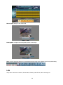
1
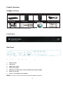
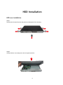
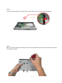
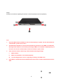
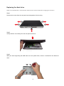
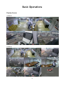
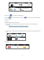
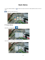
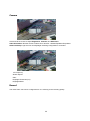
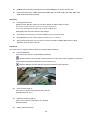
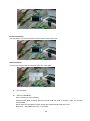
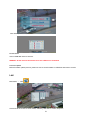
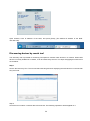
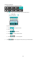
8-Channel IP Surveillance Kit User Manual C8CHIPSKIT V1.0 Introduction: This manual is for the users who attempt to use H.264 Network Video Recorder (NVR). It expresses installation guide, connecting to peripherals, and GUI operations. Please familiarize yourself with the contents in this manual before using the NVR. Make sure that you have referred to an expert when operating the outer case for repair or installing HDD. If you have any inquiries or questions, please consult your local dealer. Warning: To prevent fire or electric shock, do not expose this product to rain or moisture. Do not open the cabinet. Refer servicing to qualified personnel only. RoHS This directive restricts the use of six hazardous materials in the manufacture of various types of electronic and electrical equipment. USA (FCC) This device has been tested and found to comply with the limits of Class. A computing device pursuant to part 15 of the FCC rules. Europe (CE) By affixing the CE marking, the manufacturer assures that the item meets all the essential requirements of all applicable EU directives Japan (PSE) The purpose of the Electrical Appliance and Material Safety Law is to prevent hazards and disturbances resulting from electrical appliances Package contents ....................................................................................... 5 Front Panel .................................................................................................... 5 Real Panel ...................................................................................................... 5 HDD Installation ........................................................ 6 HDD new installation ................................................................................ 6 Replacing the Hard drive ......................................................................... 9 Basic Operations ..................................................... 11 Display Screen ........................................................................................... 11 Display Mode ............................................................................................. 13 Flexible Camera Assignment ................................................................ 14 Playback ....................................................................................................... 15 Event List ...................................................................................................... 16 Screenshot Function ................................................................................ 18 Main Menu ............................................................. 19 IP Camera Setup ....................................................................................... 19 Camera................................................................................................................................. 22 Record .................................................................................................................................. 22 Alarm .................................................................................................................................... 23 LAN........................................................................................................................................ 24 Setup ............................................................................................................. 25 3 Record........................................................................................................... 27 Alarm ............................................................................................................. 29 USB Device .................................................................................................. 29 LAN ................................................................................................................ 31 Network Access ...................................................... 33 System Requirements ............................................................................. 33 Getting Started .......................................................................................... 33 Find device IP address ................................................................................................... 33 Discovering devices by search tool ......................................................................... 34 Discovering devices in Windows Network............................................................ 35 ActiveX add-on installation ......................................................................................... 36 Web UI Operations................................................... 38 Live Viewing................................................................................................ 38 Playback ....................................................................................................... 39 Setup ............................................................................................................. 42 Log ................................................................................................................. 45 4 Product Overview Package contents NVR Remote control USB mouse Flex IR extender Power adapter Screws pack Product CD Quick Connection Guide *The actual items maybe different from the picture shown Front Panel Real Panel 1 2 3 4 5 6 7 1. Power: DC12V 2. LAN: RJ-45 3. HDMI: Video output 4. VGA: Video output 5. USB port: For USB mouse control/ USB backup/ Firmware update 6. Audio out : RCA x2 7. Video in : RJ-45 PoE x 4 (4 channels) Note: PoE ports on this device only work with PoE-enabled components. 5 HDD Installation HDD new installation Step 1: Remove the Screws from the real panel and side panel of the housing. Step2. Gently slide the cover away from the rear panel and lift it. 6 Step 3 Carefully place the HDD at the upper right side and slide it to plug into the connector properly. HDD Connector Step 4 With your hand supporting the HDD and turn the unit upside down and secure the HDD from the bottom of case with 4 screws. 7 Step 5 Screw the cover back, replacing the screws on the side panel(x4) and rear panel(x1) Note: 1. The new HDD must be formatted in order to work properly in system. For the detail about the “Format HDD”, please refer to 4.3.5. 2. The HDD will be started in 5~30 seconds after NVR is powered on. If the HDD is not detected, warning will be shown for 3 seconds by a message “HDD is not installed!” with beep every 10 seconds. You can turn off the buzzer or leave live mode to quiet it down. 3. 4. There are three reasons which may cause the above warning message: I. HDD is broken II. HDD is not installed or not installed properly III. The recording model is set as “single-way recording” and HDD is full. If the HDD is not detected and not started within 30 seconds. It will be determined as a failed HDD. 8 Replacing the Hard drive Make sure the NVR power is off and power cable has been disconnected before changing the hard drive. Step 1 Remove the screws from the rear panel and side panels of the housing. Step2 Gently slide the cover away from the rear panel and lift off Step3 With your hand supporting the HDD when turn unit upside down, remove 4 screws from the bottom of case. 9 Step4 Gently slide the hard drive from the connector properly. HDD Connector Step5 Install new HDD. Step6 Screw the cover back on the side panel (x4) and rear panel (x1). NOTE: After replacing the HDD, the new HDD must be formatted in order to work properly in system. 10 Basic Operations Display Screen 4-Channel 8-Channel 11 1. HDD Status: displays the percentage of recording space consumed on the hard disk and the size of the installed hard drive. 2. Camera Status: 4/8 channel: displays channels on the system. The red light will flash to indicate recording is in progress. 3. Tool Bar: primary control input for the user interface. Split modes Main Menu Playback/Pause Camera Event List Sequence OSD Return/Esc Screenshot PTZ 12 Display Mode Left-click on the icon to open the Split-Screen selector and choose the display mode you want. 13 Flexible Camera Assignment You can re-assign the channels to different camera. For example, you can duplicate the video feed from channel 1 onto channel 2. This is useful if you wish to re-arrange the position of each channel. For Example: Re-assigned channel 1 to channel 8. NOTE: The NVR continues to record the designated channel even if you re-assign camera positions. To re-assign camera positions: Step1 Select the channel you want to re-assign. Step 2 Click and hold the mouse, a channel menu will appear. Step 3 While holding left-click, move the mouse to the left or right to change the channel number. Step 4 Release left-click on the mouse to assign the new channel. 14 Playback Click the icon to enter playback mode. You will see a The timestamp appears in the bottom-right corner of the screen indicates the playback time. Split mode Arrow keys: day/time selector Playback / Pause Event List Show / hide OSD ESC Screenshot PTZ Click the numerals to select date / hour / minute / second or frame and adjust them by rolling up and down the mouse. 15 Playback Mark Click the bar to mark the timing of important video when searching playback data, the orange cursor will be shown in the center of the bar. Auxiliary Search Cursors: This smart search design allows you to search data quicker and easier, meanwhile, the colorful cursors are helpful to diagnose the happened events. For Example: Below picture shows many events happened, you can click the numerals of data/time/frame and “roll up or down” the mouse to move one of the colorful cursors to the center red grid to view the event. Event List Click the icon to enter the Event List mode. Each HDD is allowed to save up to 8192 events. If you change a new HDD, the event list will be moved with the old HDD. 16 Click the icon to play / pause the selected events. Click the icon to delete the selected events. Click the icon or right click the mouse to exit and go back to the previous page. Event Filter To search events by channel or event filters. 1. By Channels: click the mouse on one of below icons to show specific events by all specific channel(s). 2. By Event Filters: click the mouse on one of below icons to show specific events by different event filters. Event Details 17 In the column of filter, it will show the filter icons in different colors, you can easily search the events. When the cursor is moved to one of the events, the background will be changed to the beginning of the event. Screenshot Function Format the USB flash drive by NVR before using it for backup video, upgrade firmware or take screenshots. To take a screenshot: Click the icon to take screenshots of the main display and store the image into the USB flash drive. The file name of the screenshot will be shown on the screen after saving to the USB flash drive. NOTE: Screenshots are saved as JPEG files with the following naming convention: KMMDD00X.jpg File name K Description NVR file marker (all screenshots begin with K) MM Month DD Day X Numeral (for example : 001, 002, etc.) 18 Main Menu If you set “Password Enable” as menu. , the NVR will request at least ID:2, default password 2222 to enter the Click this icon to enter main menu. IP Camera Setup Main Menu →IP cam Setup Select certain IP cam and enter, it can set follow items: 19 1. Connect Type: Disable, Local LAN, and Internet. 2. Title: Key in IP cam title via virtual keyboard 3. Host name: Key in IP cam title via virtual keyboard 4. Port 5. ID 6. Password: Key in IP cam title via virtual keyboard 20 7. IP cam Menu: It can setup--Camera, Record, Alarm, LAN 8. IP cam Information: This allows you view all your IP cam information here, such as: OS version, S/N, IP address, DHCP, Http….. 9. IP cam firmware update 21 Camera Click and roll the mouse to adjust Brightness, Contrast, and Saturation. Video Orientation: Roll the mouse to select mirror function:--Disable/Flip/Mirror/Flip+Mirror. Advanced Setup: Light sources and Day/Night switching configurations. It includes AC Frequency: Shutter Speed: Gain: Day/Night Threshold (Lux) Day/Night Mode Record The video frame rate can be configured here. It is referring to the recording quality. 22 Alarm/Motion Rate: set the frame rate when an alarm or motion event is triggered. Working Rate: set the frame rate for normal working hours Non-working Rate: set the frame rate for the time period other than working hours Quality: set video quality. It refers to the bit rate generated Schedule: configure the working / non-working time periods. Alarm Motion Enable: Enable/Disable motion detection Alarm Setup: Response Duration Motion Alarm Schedule 23 Motion Setup: Setup IP cam motion field. Privacy Mask: configure the mask (hidden) areas on the image. Note: click the split mode button can select/deselect all the image area in Motion and Privacy Mask setting. LAN Setup the IP camera’s IP address, Subnet Mask, Gateway, DNS Server, DHCP and Http port. 24 Setup Main Menu Setup Maintenance: the NVR settings can be perfromed with the below 3 types of acti. Load Factory Default: restore all NVR settings to the default Backup Settings (to USB): store the current NVR settings, so it can be applied to another unit of NVR. Restore Settings (from USB): restore settings based on the stored backup settings Language: The NVR supports 21 version of OSD language: English, Spanish, French, Italian, Russian, Danish, Swedish, Finnish, Czech, Dutch, Deutsch, Polish, Hebrew, T-Chinese, S-Chinese, Japanese, Thai, Vietnamese, Korean, Turkish and Portuguese. Fan Speed: The lower the fan speed, the quieter the fan sound, but the higher the HDD temperature, vice versa. Sequence Time: For sequence displaying, the dwelling time (before displaying next group) can be set. Video Out: 25 HDMI Screen size: Move the adjust bar to make HDMI out to fit the monitor size Video-Out Resolution: HDMI 1920*1080, HDMI 1280*720, VGA 1920*1080, VGA 1680*1050, VGA 1280*1024, VGA 1024*768: Date/Time: Configure Date/Time Display Format: Roll the mouse up or down to adjust as Y/M/D, D/M/Y or M/D/Y. Date Setup: Click and roll the mouse up or down to adjust date. Time Setup: Click and roll the mouse up or down to adjust time. Exit/Update: Exit this menu and save the settings Time Zone: This allows you to select GMT for your local time zone. Daylight Saving Time: You are able to choose +0, +1, +2 on it. Synchronize with NTP: You are able to choose OV, NIST or MIST (Microsoft) on NTP (Network Time Protocol) Server. Password: Only users of ID: 3, default password:3333 can manage NVR Passwords. Password Enable: Click and roll the mouse to enable/disable password. Password Enable: the NVR will request password to enter main menu, playback or event list. Users without password are allowed for live monitoring only. Password Disable: the NVR will NOT request password for NVR operation. User Password (ID:1): User of ID:1 is able to view playback and event list. (Default password: 1111) Operator Password (ID: 2): User of ID:2 is able to enter main menu. (Default password: 2222) Admin Password (ID:3): 26 User of ID:3 is able to manage NVR & LAN password. (Default password:3333) Information You are able to check the NVR information including software, hardware, start / stop recording time of HDD and LAN. Record Main Menu → Record Video Information You can choose one of the cameras to see the video size at each hour. 27 Bit rate Information You can choose one of the cameras to see the bit rate size at each hour. HDD Information You can view internal HDD and external HDD info. in this page. Record Mode External HDD Mode Click to select one of the following: Extended REC: NVR recording data into internal HDD first, when it record to 100%, it’ll record to external HDD. Mirror: NVR recording data into both internal and external HDD at the same time. Read Only: Read HDD data only, no recording. 28 Select Format HDD Choose which HDD (Internal / external) is going to be formatted. Format HDD Cancel HDD format. Format HDD. WARNING: All the recorded data including event list will be deleted once HDD is formatted. Alarm Main MenuAlarm Buzzer Roll the mouse to enable/disable buzzer. Key Buzzer Roll the mouse to enable/disable key buzzer. Alarm Setup Vloss Response Time Video loss response time can be set from 0,3,5,10,30, 60,120,180 seconds to infinite. Alarm full screen: Enable: Screen will pop out when alarm/ motion are triggered. Disable: Screen will not pop out when alarm/ motion are triggered. USB Device Main Menu → USB Device To format USB flash drive by the NVR before using it for backup video upgrade OS. The NVR support 2GB~16GB capacity of USB flash drive 29 Start / Stop Time & Select Channel Insert USB flash drive into the NVR. Click and Roll the mouse to set the start / stop time and channel which is going to be saved to USB flash drive NOTE: One USB flash drive can save maximum 16 files. Each file is up to 1GB or 30 minutes. Save To Device Insert USB flash drive into the NVR, it will show “USB Check OK!” on the screen Click “Save to Device” to backup the video to USB flash drive, it will start storing the backup file. The file will be named by Start Time as “Ch_YYYYMMDDhhmmss.mov” 30 After backup is finished, check the event list to see if it is successful. Format Device Insert a USB flash drive to format it. WARING: All the data will be deleted once the USB drive is formatted. Firmware Update Before firmware update process, please be sure to save firmware to USB flash and insert it to NVR. LAN Main Menu → LAN Click and roll the mouse to set IP, Mask, Gateway, DNS Server, DHCP, Http Port. 31 LAN Password Only the users of “ID: admin”(default password : 3333) are able to manage LAN passwords Click the numerals to set password. User Password (ID: user): User of ID:user is able to view remote live only. (Default password: 1111) Operator Password (ID: operator): User of ID:operator is able to view remote live, playback and backup. (Default password: 2222) Admin Password (ID: admin): User of ID:admin is able t to set IE parameters including PPPoE and DDNS settings...etc. (Default password:3333) 32 Network Access System Requirements Description Requirement CPU Pentium 4 3.0GHz or above Operating System Windows XP/ Vista/ 7 / 8 / 8.1 Memory 1 GB RAM Video 256 MB of video memory Network (LAN) 10/100 Base T Network Internet Explorer 7 or above Browser Google Chrome / Mozilla Firefox *with the installed IE Tab plug-in Quick Time Player Media Player Getting Started The default ID and Passwords User Account ID Password Guest user 1111 Operator operator 2222 Admin admin 3333 Find device IP address The device IP address can be found in local NVR configuration. Enter Menu -> Setup and then click on Information. The device information is presented as figure below. Find IP address in LAN. 33 Open browser, enter IP address of the NVR, and press [Enter] (The default IP address of the NVR: 192.168.0.89) Discovering devices by search tool The discovery tool is provided for searching Conceptronic network video devices in a network. When NVR device is correctly installed in a network, it can be searched by the tool. The steps of applying this search tool are as below. Step 1 Launch the Discovery Tool. The tool will start searching and then displaying the NVR devices on the list after they are found. Step 2 Check the box to select a camera device from the list. The following operations will be applied on it. 34 Step 3 The selected NVR may have been assigned a valid IP address via DHCP server. It can also be manually given an IP address. To do so, click on “Set IP” button. In the pop-up “Set IP” window, input the IP, Subnet Mask and Gateway. Input account info if NVR is password protected Step 4 Click on the “Browse” button. This will launch an IE browser and link to the NVR web page immediately. Discovering devices in Windows Network The NVR can be discovered in “Windows Network” of a client PC when it is connected in a network with DHCP and UPnP services available. See the figure below. Right-click on the device and select “Properties”, the pop-up window shows all the information related to the device, including the web access info. Use the web address to connect to the NVR. Or simply double-click on the selected device, which gets immediately access to the NVR webpage. 35 ActiveX add-on installation The access to the NVR webpage for the first time will be prompted to install the ActiveX. This installation is essential for viewing live video via IE browser. To allow the installation, click “Install” button on the message bar. Follow the instructions to complete the installation. NOTE If there is not any prompt message or ActiveX cannot be installed at all, change the IE security level and settings. In IE Internet Options Security Custom level, make sure the “Download signed ActiveX controls” setting is “Enable” or “Prompt” selected. 36 Enter ID and Password to login. The IE browser can then display the web UI of the NVR and the live video of the managed cameras as below. 37 Web UI Operations Live Viewing Click this button for live mode. Click this button to view in single channel Click this button to view in Quad mode Click this button to view in 9-split mode. Drag & Drop (or tick/untick) the selected camera from the list to the viewer channel. 38 View in video image as1600*1200. View in video image as 640*400. Switch automatically to HD or SD resolution when viewing in shingle channel or multi channel mode respectively. Press this button to capture current live image. Press this button to record image to PC. Press this button to digital zoom in single channel. Press this button to enlarge image to full screen, press keyboard “Esc” to return. Press this button to expand image to fit image window size. Press this button to hide the OSD text overlap. Press this button for camera sequence This show user online status, maximum allow 8 users online. Playback Click this button for playback mode. Playback mode by Date/Time Playback model by event Click this button for remote backup NOTE Only operator and admin are able to enter playback mode 39 Playback by Date/Time 1. Select the channel you would like to playback 2. Click to open a pop-up calendar to select the date and time. To use the pop-up calendar: A. Click to change the month. B. Click a date C. Click 3. to set the time. D. Click .The pop-up calendar closes. E. Click to control playback. Click to control playback rewind, pause, play and fast-forward. 40 Playback by Event You can search events by “Motion” “Sensor’ and “All” Or click select the date and time. Press this button to open a pop-up calendar to to search event list Backup Select a time period that will be exported as a video footage. 1. Select start/end time 2. Select Channel 3. Click on “Start” button (become “Stop” when it is being processed). The video exporting would start immediately. 41 Setup Click this button for full remote setup mode Press this button for following setting: Press this button for following setting 42 Press this button for following setting: Press this button for following setting: Press this button for following setting: 43 Press this button for IP, E-mail, PPPoE, DDNS setting: Press this button for following setting: Press this button for following setting: 44 Press this button for following setting: Log Click this button for log mode. Press this button for system info. Press this button for network info. Press this button for online user info. 45 46 SYSTEM Operating System PLAYBACK Linux (embedded) Channels Max. 8Ch Simultaneous View, Record, Playback, Pentaplex Single Frame, Forward / Rewind Playback Speed Backup & Remote Monitoring Number of Channels (x5, x15, x60) 4 + 4 Channels INPUTS / OUTPUTS Search By time or event Log Search Yes (max. 8192 events) Camera Input 4Ch(PoE) + 4Ch(LAN) STORAGE & ARCHIVE Video Output (VGA) Up to 1920x1080 Storage Internal HDD x1, External USB HDD x1 Video Output (HDMI) Up to 1920x1080 Maximum Capacity 4TB Audio Out RCA x2 (Left & Right) Backup Media USB Flash Drive & External HDD USB Port 3 Backup File Format MOV DISPLAY / OPERATIONS External HDD mode Capacity extending / Backup recording Live Display Up to 8 CONNECTIVITY Live Display Speed Up to 120 fps Easy Connect OSD Yes Supported UPnP Supported Operating Windows™ 8/7/Vista/XP Systems USB Mouse, IR Remote Controller, Internet Explorer & Safari & Chrome System Navigation Browsers Touch Monitor Control & Firefox Split Screen 1, 4, 9 Email notification Yes Motion Area Setting Yes (50x37) Smart Phone Compatibility iOS, Android Motion Sensitivity 100 levels DDNS Yes Digital Zoom Yes, 1x ~ 4x System Configuration Full setup configuration over network Privacy Mask Yes Network Protocol TCP/IP, PPPoE, DHCP, DNS, DDNS, NTP, SMTP, UPnP 10/100 Mbps RJ45 x 1 User Authority Yes Network Interface Independent 10/100 M RJ45 (PoE) x 4 Time Synchronization NTP Supported GENERAL Firmware Upgrade Via USB flash drive Power Consumption DC12V, 4A, 48W Supply Voltage 100~240VAC RECORDING Unit Dimensions (W x D x Compression Type H.264 295 × 161.1 × 32.2mm H) Compression Rate 300:1 Unit Weight 0.85Kg (without HDD) Recording Resolution Up to 1600x1200 Operating temperature 5 ~ 40°C Recording Speed Up to 120 fps Humidity 10 ~ 75% Recording Quality Control 5 levels Recording Schedule Manual / Schedule / Event Pre Recording Up to 15 Secs Post Recording Up to 10 Minutes Reliability Auto-recovery after power resuming 47 Note: NVR Viewer app for iPhone and Android phones is available on the App store and Google Play. For the app user manual, please visit http://www.conceptronic.net/download.php Notification of Compliance Appendix A Europe - EU Declaration of Conformity For complete DoC please visit http://www.conceptronic.net/download.php GPL License Agreement GPL may be included in this product, to view the GPL license agreement goes to http://download.conceptronic.net/GPL/GPL.pdf For GNU General Public License (GPL) related information, please visit http://www.conceptronic.net/download.php Enjoy the use of your Conceptronic 8-Channel IP Surveillance Kit! 48