1
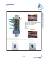
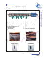
WINCHES
6
OPERATION
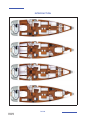
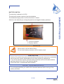
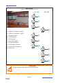
SETTING THE SAILS
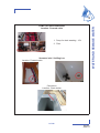
CLASSICAL MAINSAIL
With the mainsail being on the deck:
- Screw the pins of the mast sliders for battens into their boxes.
- Slide in the battens through the leech.
- Screw the box cap until you get the required tension (the tightening screw shall not
project beyond the sail).
- Do not forget the small locking screw.
- Put the mainsail into the lazy-bag.
- Fit the mainsail onto its slides, begin with the headboard and finish with the tack.
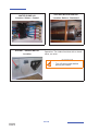
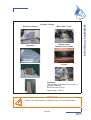
WARNING
-Refer to the manufacturer's instructions to remove the winches and put
them back.
Improper refitting may result in accidents (e.g. kick of the crank handle).
57/166
090282
Index G
RIGGING AND SAILS
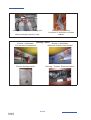
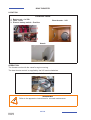
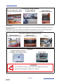
Avoid rope jamming during winch handling. Do not leave loose ropes on the winches but
make them fast on cleats (except on the ’’Self Tailing’’ winches).
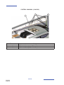
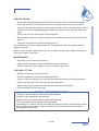
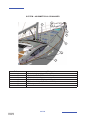
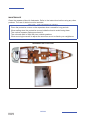
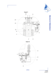
SYSTEM - MAINSAIL (CLASSIC)
2
Reference
1
2
3
Designation
Kicker tackle
Swivel single pulley - 100 mm diameter
Mainsail sheet (D 12mm L 45 m)
58/166
090282
Index G
1
3
6
RIGGING AND SAILS
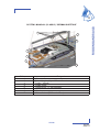
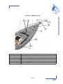
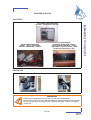
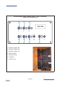
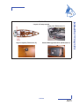
SYSTEM - MAINSAIL (CLASSIC) “GERMAN SHEETING”
2
1
7
5
4
6
3
Reference
1
2
3
4
5
6
7
Designation
Kicker tackle
Swivel single pulley - 100 mm diameter
Pulley - Vertical
Single clutch
Cheek block - 57 mm diameter
Winches
Mainsail sheet (D 12mm L 45 m)
59/166
090282
Index G
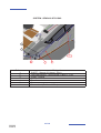
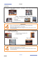
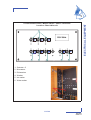
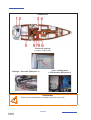
SYSTEM - GENOA & STAYSAIL
2
1
4+5
Reference
1
2
3
4
5
6
6
3
Designation
SHEET - Staysail (D 14mm L 25 m)
Cable adjustment - Genoa sheet (D 8mm L 21 m)
Pulley - Vertical
Traveller - double
Genoa car
Genoa sheet (D 14mm L 35 m)
60/166
090282
Index G
1
6
RIGGING AND SAILS
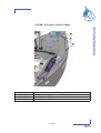
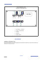
SYSTEM - STAYSAIL TAKE-UP DRUM
1
2
3
Reference
1
2
3
Designation
Staysail take-up drum
Swivel plates - D 10mm
Swivel plates - D 6mm
61/166
090282
Index G
FURLING MAINSAIL
- Remove the hatch giving access to the furling mechanism.
- Spread out the sail on the deck.
- Fasten the head (strap) to the shackle of the upper swivel. Pay attention to the winding
direction.
- Insert the foot adjustment line into the clew block.
- Slowly hoist the sail. Guide the bolt rope (sometimes the groove leading edges may be
insufficiently smoothed off).
- When the sail is up, tack it to the lower shackle.
- Gently sweat up the halyard.
- Refit the hatch.
- Furl the sail facing the wind and keeping a very slight tension on the foot. The mainsail
downhaul and sheet shall be eased off.
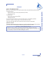
ADVICE - RECOMMENDATION
- Carry out the complete maintenance of the winches regularly (before and during the
sailing season).
- Rinse the winches off regularly during the season.
62/166
090282
Index G
6
FURLING GENOA
- Secure the head and halyard to the swivel. Secure the tack to the drum and sheets.
- Have the halyard taut enough but hoist less taut than a sail on a normal stay. Hoist it
until the horizontal creases disappear (Adjust the tension of the luff after a few sea
trips).
- Pull on the line from the cockpit to furl the genoa.
- Before getting under way take advantage of a windless period of time and hoist the
genoa.
- Hand pre-roll the drum to set the furling line on it.
Pay attention to the drum winding direction: The sacrificial strip of the genoa shall be
wrapped outside.
Never force it in case it seizes when you furl or unfurl the head sails. Make sure that no
ropes are caught in the furler.
MAINTENANCE
- Regularly rinse the drum and swivel.
- Lubricate the bearings if recommended by the manufacturer.
- Remove the sails if your boat is not to be used for a long time.
LAZY-BAG: FITTING
- Spread out the lazy-bag on the deck.
- Slide the battens in and close the batten pockets.
- Hank on the lazy-bag until you have the front part about level with the gooseneck.
- Fasten the lazy-bag to the tack with the strap provided.
- Stretch the lazy-bag from the back before you fasten the lazy-jacks.
- Put the mainsail into the lazy-bag.
ADVICE - RECOMMENDATION
-
When you are not sailing, slacken the genoa halyard.
Install the lazy-bag before the mainsail.
When the sail is unfurled, adjust the halyard tightness.
Too much tightness may cause furling problems.
After taking in a reef for the first time mark the halyard position at the clutch (marker
pen or light stitched label)in order to be able to let out the sheet with precision in
subsequent manoeuvres.
63/166
090282
Index G
RIGGING AND SAILS
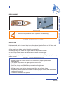
- Insert the bolt rope into the hole and hoist it and take care that you do not tear it.
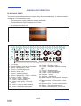
AUTOMATIC IN-MAST REEFING BLOCK DIAGRAM
ADVICE - RECOMMENDATION
- At the end of the sailing season, and if possible before winter, leave your sails to a
specialist to have efficient maintenance and repairs.
Reef 1
Reef 2
64/166
090282
Index G
Reef 3
6
RIGGING AND SAILS
SYSTEM - SYMMETRIC SPI
6
2
1
2
2
3
5
2
4
Reference
1
2
3
4
5
6
Designation
Boom
Swivel single pulley - 100 mm diameter
Spinnaker boom downhaul (D 12mm L 30 m)
Spinnaker sheet (D 14mm L 40 m)
Spinnaker guy (D 14mm L 40 m)
Boom lift (D 12mm L 48 m)
65/166
090282
Index G
SYSTEM - ASYMMETRICAL SPINNAKER
1
5
7
6
3
2
1
4
Reference
1
2
3
4
5
6
7
Designation
Swivel single pulley - 100 mm diameter
Spinnaker tack (D 12mm L 18 m)
Tackle block
Spinnaker sheet (D 14mm L 40 m)
Spinnaker halyard (D 12mm L 55 m)
Bobstay
Acorn nut
66/166
090282
Index G
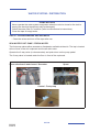
SAILS
6
The working life of a sail mainly depends on its being regularly maintained.
Avoid wear and tear: Use protective items against chafing on the the accessories with
rough surfaces (protective items for spreaders, stanchions etc.).
Have a sail maker's kit and a user's manual so that you may carry out the emergency
repairs waiting for the sailmaker's assistance.
AUTOMATIC REEFING SYSTEM
When you reef down automatically, the mainsail halyard shall not be too loose, otherwise
the reefing blocks take up improper positions.
The diagram shows the path of the automatic reef line and does not indicate the standard
take system.
SHORTENING THE STANDARD MAINSAIL
To shorten sail:
- Head into the wind.
- Slacken off the kick strap.
- Slightly slacken the mainsail sheet.
- Slightly slacken the mainsail halyard.
- Take in the reef line.
- Take up the slack in the mainsail halyard.
- Reset the mainsail sheet.
- Take up the kick strap slack if necessary.
SHORTENING THE FURLING MAINSAIL
To reduce the surface area of the mainsail:
- Gradually take in the mainsail furling line while letting out the foot tack line (keep the
boom perpendicular to the mast).
CLEANING AND MAINTENANCE
Rinse the sails with fresh water from time to time and dry quickly in order to avoid mildew.
Avoid drying the sails to windward when on the mast (when the sails lift, the seams are
worn, the sails may be torn by the rigging).
67/166
090282
Index G
RIGGING AND SAILS
When sailing, trim the sails properly in accordance with the stresses in order to reduce
the harmful strains on the fabric.
HAULING DOWN THE STANDARD MAINSAIL
To haul down the mainsail:
- Haul up.
- Slacken off the kick strap.
- Take up the slack in the Lazy bag ropes.
- Slacken off the mainsail halyard while taking up the reef lines to control the mainsail
descent.
- Fold the mainsail into its lazy-bag.
- Take up the mainsail sheet to immobilise the boom.
- Immobilise the mainsail halyard.
SAIL STORAGE/FOLDING
Avoid storing a wet sail to prevent the appearance of mould and mildew.
Flake the sail parallel to the foot, then roll it up to the bag dimensions.
PROTECTION
UV rays are harmful to polyester and nylon. If the sails remain on the mast, even for 24 h,
protect them with a cover or a protection fabric placed on the leech and foot of the furled
sails.
Our distributor network offers you accessories that have been selected by the yard and are
consistent with your needs.
68/166
090282
Index G
7
INTERIOR
INTRODUCTION
INTERIOR MAINTENANCE
MAINTENANCE OF FABRICS
69/166
090282
Index G
INTRODUCTION
70/166
090282
Index G
INTERIOR MAINTENANCE
7
- Take advantage of the fine weather to take the settee and berth cushions out.
- Put the cushions vertically if you leave the boat for long.
- Use blinds to protect the inside of the boat against UV rays.
- Carefully remove all crumbs.
- Make sure the bilges are clean and dry.
INSIDE VARNISH
- Rinse the inside varnish with fresh water mixed with spot remover and shampoo.
- Polish the interior varnishing with a chamois leather.
MAINTENANCE OF FABRICS
STAIN REMOVAL
- Dab with a clean rag.
- Remove the stain with a solvent poured onto a clean rag. Never pour the solvent
directly over the stain.
- Rub with a clean and dry rag.
- Brush the fabric against the grain.
- Use the vacuum cleaner when the fabric is dry.
PVC OR COATED FABRICS
- Use a sponge and water and soap (household soap type).
ADVICE - RECOMMENDATION
-
Preferably wash your boat on shore.
Use as few cleaning agents as possible.
Don't discharge cleaning agents into the water.
Take the removable upholstery inside when the vessel is not being used.
Place protective covers/awnings.
Mark up each cover and foam when dismantling.
PRECAUTION
- For the PVC fabrics, don't use any solvent or solvent based product (pure alcohol,
acetone, trichloroethylene).
71/166
090282
Index G
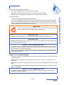
INTERIOR
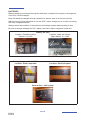
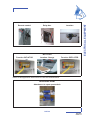
INTERIOR
Armrest - Saloon
Mechanism Opening / Closure - Dining table
Blackout curtain
Companionway
Side portholes
Deck hatch
72/166
090282
Index G
WARNING
Handle the blackout curtains with care.
Do not use the companionway sun visor in strong winds, rain or while
sailing.
100% POLYESTER/DRALON JACQUARD
If you cannot remove the fabric:
- Clean with the vacuum cleaner.
- Clean with a foam for synthetic fabrics (please refer to the product instructions).
If you can remove the fabric:
- Hand wash with an ordinary washing powder at 30° C.
In both cases, dry cleaning is possible. Remove the stains as soon as possible with a damp
rag.
COTTON JACQUARD
- Dry clean.
- Do not iron.
- Do not use hypochlorite.
- Remove the stains with fractionated petrol.
73/166
090282
Index G
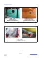
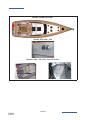
INTERIOR
7
Sink + Draining rack - Galley
Vegetable bin
Safe
Location: Port aft cabin
Access - Engine compartment
Danger:
Must be closed while sailing.
Adjustable berth - Port forward cabin
Bench seat
Berth
Fixing
74/166
090282
Index G
INTERIOR
7
Adjustable berth - Starboard forward cabin
Extensions - Bed
Fixing
Cooker
75/166
090282
Index G
8
WATER AND SEWAGE WATER
WATER TANKS
WATER SYSTEM - DISTRIBUTION
WATER SYSTEM - DRAINAGE
SEWAGE
77/166
090282
Index G
WATER TANKS
Location: Saloon
Capacity: 3 x 310l
Gauge
Position / Number of water tanks
WATER TANK
Deck filler
Selection valve - Water tank
Location: Plumbing board
1. Supply - Water tank - Starboard forward
2. Supply - Water tank - Port forward
3. Supply - Water tank - Starboard aft
78/166
090282
Index G
8
OPERATION
In order to prevent any handling mistakes, never fill the water and fuel tanks at the
same time.
Open and close the filler caps with the suitable key.
Check the filler cap seals for condition during filling.
The tanks are fitted with overflow outlets and vents.
Never insert the water filling hose deep down into the system in order to prevent any
over-pressure in the systems.
ADVICE - RECOMMENDATION
- Pay attention to the quality of the water for the filling up. Check if it is drinking water.
- It is possible to sterilize the tanks with a Clonazione tablet (sold at the Chemist's).
- If the boat is not used for long, purify the tanks and pipes with acetic acid (or white
vinegar).
- For winter storage instructions and precautions, refer to Chapter 13.
WARNING
- The tanks' nominal capacity cannot be fully used due to the load and the
need to maintain the correct trim. A 20% reserve should be kept
79/166
090282
Index G
WATER AND SEWAGE WATER
During filling, avoid handling contaminants near the fillers.
220V 60L WATER HEATER
Location: Saloon - Starboard
WATER PUMP 24V
Location: Saloon - Central
SOCKET - SHORE WATER
Location
Operation: The intake functions with a check
valve, no valve.
WARNING
- Turn off shore water before
leaving the vessel.
80/166
090282
Index G
8
WATER AND SEWAGE WATER
PUMP FOR DECK WASHING
Location: Forward cabin
1. Pump for deck washing - 12V
2. Filter
Seawater inlet / Stuffing box
Location: Forward cabin
Connection
Location: Chain locker
81/166
090282
Index G
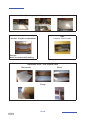
WATER SYSTEM - DISTRIBUTION
PRECAUTION
- Never operate the water system equipment when the valve is closed or the tank is
empty (the electrical equipment may be damaged).
- Check the water filter for condition (refer to manufacturer's instructions).
- Close the taps of empty tanks.
USE OF THE WASHBASINS AND SHOWERS
- Close the valves and turn off the taps after use.
SEA WATER FOOT PUMP / FRESH WATER
The footpump makes either seawater or freshwater available at the sink. The tap is located
at the corner of the sink cupboard and the aft cabin door.
Operate the 3-way valve (to choose water) and push down on the pump pedal.
The 3-way valve is located under the floor in front of the cupboard.
Valve selection of water board / Sea water
Control - Foot pump
82/166
090282
Index G
Spout
8
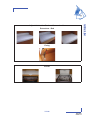
WATER AND SEWAGE WATER
DECK SHOWER
WARNING
- Bleed the cockpit shower water system to avoid freezing.
WATER SYSTEM DRAINAGE
OPERATION
Waste water from the sink, washbasins and heads is drained off by thru-hull fittings with
ball valves (the valve is closed when the valve handle is perpendicular to the hose, the
valve is open when the valve handle is in line with the hose).
All the floors have holes (limber holes) for the water flow.
A watertight bilge tray under the engine receives the possible oil leaks.
A main sump located above the ballast receives water from the bilges.
The main sump is partially drained by an electric or a manual pump. Regularly dry the sump
with a sponge.
ADVICE - RECOMMENDATION
- Regularly check the valves and thru-hull seacocks for proper operation and
watertightness.
- Turn off the valves when the water system is not in use.
- Visually check the water pump flow.
- Check the clamps and flexible hose connections for tightness.
- Pay attention to the seals for condition.
- Regularly make sure that the strum box and bilge are perfectly clean.
- Immediately switch off the electric system in case a pump is running while all the water
supplies are turned off.
- In case of a leak check the system.
83/166
090282
Index G
Drainage - Galley sink + Draining rack
Icebox drainage: directly to well.
Drainage - Dishwasher:
Connector to sink drain in kitchen
cabinet.
Drainage - Head
Shower + Washbasin
Port aft head compartment
Shower + Washbasin
Starboard aft head compartment
Shower drainage switch
Drainage - Washer: Starboard saloon
84/166
090282
Index G
SEWAGE
8
USE OF THE MARINE HEADS
To empty the bowl:
- Set the control lever of the pump slantwise (FLUSH).
- Operate the pump.
To dry the bowl:
- Set the lever back vertical (DRY).
- Operate the pump.
To avoid blocking the toilets only use absorbent paper in reasonable quantities.
Schedule a regular rinsing through of the heads with fresh water.
Close the valves after each use (in particular when the boat is unattended).
ELECTRIC TOILET
The electric toilets operate with seawater only. A switch enables the water intake and drain
cycle of the bowl to be activated. A switch enables the bowl to be rinsed.
ADVICE - RECOMMENDATION
- When you are in a marina, use the club-house sanitary facilities (if there are).
- Since it is prohibited to discharge sewage water in certain marinas or countries it may
be necessary to use the foul water holding tank ('WHT').
85/166
090282
Index G
WATER AND SEWAGE WATER
Before you use the heads, check that the water intake valve and draining valve are open.
TOILET OPERATION QUIET FLUSH (OPTIONAL)
1
2
Control WC quiet flush
1. Rinsing out the bowl
2. Water filling to the left and bowl draining to the right
Pump Seawater inlet + Filter
1. Seawater inlet - WC
2. Filter
3. Pump - WC
USE OF MARINE HEADS EQUIPPED WITH A WASTE HOLDING TANK (WHT)
Open the water intake valve (valve handle parallel to the pipe).
In the case of a direct discharge into the sea: Open the draining valve.
In case you store the waste waters in the tank: Make sure the draining valve is closed
(valve handle perpendicular to the pipe).
To drain the bowl, set the control lever of the pump slantwise (FLUSH) then operate the
pump.
To dry the bowl, set the lever vertical (DRY) then operate the pump.
86/166
090282
Index G
In order to avoid clogging the heads:
To empty the tank:
- In an authorized area, open the draining valve.
- In a marina equipped with a system to suck the waste waters, put the sucking hose
into the tank through the deck filler. Start the pump of the sucking system. The filler
caps are opened and closed with an appropriate key. When the tank is empty, check
the cap seal for condition then close the filler.
WARNING
- Ask for information about the laws in force in your country or your marina
about discharging your waste waters into the sea.
PRECAUTION
- Close the valves after each use and above all when the boat is unattended.
PRECAUTION
- Regular check the tank level. High pressure due to too high a level may cause leaks
or more unpleasant troubles.
ADVICE - RECOMMENDATION
- To prevent odors caused by organic waste in pipes one should clarify the circuit after
each use. For this procedure, drive about ten times the manual pump of the toilet or
for a minute if it is an electrical pump
- .When you leave the ship for several days, flush the toilets circuit assembly with fresh
water. Purify with specific products (for example a health additive to clean, disinfect
and neutralize odors).
RESPECT OF THE ENVIRONMENT
- Remain informed of local regulations concerning the environment and follow the codes
of best practice.
- Do not drain the contents of the sewage tank near the coast or in zones where it is
forbidden.
- Make use of the port or marina pump facilities to drain the sewage tank before leaving
port.
- Find out the international regulations against marine pollution (Marpol) and follow them
as far as possible.
ADVICE - RECOMMENDATION
- Completely empty the black water system before leaving the vessel unattended in
temperatures below freezing.
87/166
090282
Index G
WATER AND SEWAGE WATER
8
- Only use absorbent paper inreasonable quantities.
- Schedule a regular rinsing through of the system with fresh water.
- Always retain a little water in the bottom of the bowl to avoid smells
Detail - Tank
Capacity: 80 litre
Location: in each bathroom
Excrement tank gauge +
Control - Drain to sea
Location: Cupboard - Head
Fore washroom
Aft washroom
1. Drain to sea
2. Seawater inlet - WC
88/166
090282
Index G
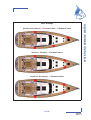
8
WATER AND SEWAGE WATER
Deck drainage
Version 2 aft cabin(s) - 1 Forward cabin - 1 Skipper's cabin
Version 1 aft cabin - 3 Forward cabins
Version 2 aft cabin(s) - 3 Forward cabins
89/166
090282
Index G
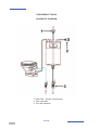
EXECREMENT TANKS
SCHEMATIC DIAGRAM
1. Deck filler - Suction and Rinsing
2. Tank vent hole
3. Thru-hull seacock
90/166
090282
Index G
9
ELECTRICAL EQUIPMENT
GENERAL INFORMATION
12 V DC SYSTEM
24 V DC SYSTEM
110-220 V AC SYSTEM
EQUIPMENT
91/166
090282
Index G
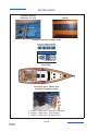
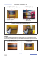
ELECTRICAL EQUIPMENT - 12V
BATTERY SWITCH - 12V
Location: Companionway - Starboard
1. Common negative
2. Service positive
3. Positive engine
BATTERY SET - 12V
Location: Chart table
1. Motor: 60A
2. Service: 50A
BATTERY CHARGERS - 12V 25A
Location: Companionway - Starboard and port
BATTERY CHARGER
Operation
The battery charger operates based on a signal processor that converts alternating current
(220V or 110V) into a direct current (12V). The operation of the charger is fully automatic, after
selecting the type of battery and load type (Refer to the instructions for use).
VOLTMETER - 12V
Location: Electrical panel
GENERAL FUSE 12V SYSTEM
92/166
090282
Index G
12V BREAKER
Location: Electrical panel
1.
2.
3.
4.
5.
6.
7.
Sockets 12V - Cockpit + Electrical panel
Sockets 12V - Forward cabin
Sockets 12V - Aft cabin
Hifi
Amp - TV
VHF
Available
Mechanism
Circuit breakers are resettable.
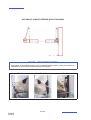
Press the tab manually on black back on the road circuit (see photo)
Breaker disarmed
Armed breaker
93/166
090282
Index G
ELECTRICAL EQUIPMENT
9
GENERAL INFORMATION
ELECTRICAL PANEL
The electrical switchboard does not require any routine maintenance. In case an electric
appliance is not energized, check:
- The main power supply (batteries, battery switches).
- The switches and circuit breakers on the line.
- the relevant electrical unit.
5
6
7
8
9
10
11
12
13
14
15
16
17
18
19
20
21
22
23
24
25
26
27
4
OFF
3
+
FF
O
V
-
AMP
12V
GAS
24V
AMPS
VOLTS
INT
EXT
2
ON
ON
OFF
1
1
2
1
OFF
1
2
2
AUTO
ON
AUTO
ON
WATER
3
3
1
2
3
4
4
Scheiber
DC - 10A MAX
DC
1. 12V socket
2. "Interior lighting" general circuit-breaker
3. Switch - Backlighting - Panel
4. Control - Forward bilge pump
5. Control - Water unit
6. Control - Fridge - Galley
7. Control - Saloon lighting 1
8. Control - Bilge pump - Saloon - Auxiliary
9. Control - Freezer - Galley
10. Control - Fridge - Chart table
11. Control - Saloon lighting 2
12. Control - Bilge pump - Principal Saloon
13. Control - Pump for deck washing
14. Control - Navigation electronics
15. Control - Solenoid - Gas
16. Control - Navigation lights & Mooring
light
17. Forcing - Steaming light
18. Control - Projector boom bar
19. Control - Deck searchlight
20. Indicator - Voltage
21. Indicator - Water level
22. Master switch - Measurement - Voltage
23. Master switch - Water level measure
24. Master switch - Measurement - Level
Fuel
25. Master switch - Current measurement
26. Display - Current measurement
27. Display - Measurement - Level Fuel
94/166
090282
Index G
ELECTRICAL CIRCUIT, 24 V
- Never work on a live electric fitting.
- The batteries must be strongly fastened.
- Do not block the battery ventilation ducts, some of them may give off hydrogen which
represents a danger of explosion.
- The batteries must be handled with care. In the case of contact with electrolyte
thoroughly rinse off the affected part of the body and consult a doctor.
- To avoid short-circuiting between the battery poles do not store conducting objects near
to the batteries (metal tools, etc...).
- Turn off the electrical circuit with the battery switches when installing batteries or during
their connection/disconnection.
- Never modify the specifications of power overload protection devices.
- Never modify an installation. Use the services of a qualified marine electricity technician.
- Never install or replace the electric appliances (or any electric equipement) by
components exceeding the capacity (amperage) of the circuit.
- Do not leave the vessel unattended when the electrical system is switched on .
- Certain lights represent a significant heat source, be careful of surrounding objects.
Note, the son of the 24 V circuit are white or brown for the blue and more for less.
DANGER
- There may be danger of fire or explosion if direct current systems are
incorrectly used.
WARNING
- Handle the batteries with care (Please refer to the manufacturer's
instructions.
- In case of electrolyte splashing, thoroughly rinse the part of the body that
has been in conctact with it. Obtain medical advice.
ADVICE - RECOMMENDATION
-
Keep the batteries clean and dry in order to avoid premature wear.
Periodically check the electrolyte level. Add distilled water when needed.
Tighten and maintain the terminal connectors by greasing them regularly.
Disconnect the batteries during winter storage or long periods of inactivity.
95/166
090282
Index G
ELECTRICAL EQUIPMENT
9
GENERAL RECOMMENDATIONS
BATTERIES
Battery charging is achieved through the alternator coupled to the engine or through use
of the 220 V shore charger.
Keep the batteries charged enough (essential to ensure them a correct service life).
Make the most of time alongside to use the 220 V shore charger so as to start out sailing
with fully charged batteries.
Always check the condition of the batteries and charge system before putting to sea.
Be sure to always recharge the 24 V battery set after a day's navigation under sail.
Battery set: 24V
Location: Starboard saloon
Service: 4 x 120A
Location: under the kitchen
Spare battery: 4 x 120A
Battery chargers - 2 x 24V 60A
Location: Under map table
Voltmeter - 24V
Location: Electrical panel
General fuse - 24V system
96/166
090282
Index G
9
BATTERY SWITCH
The electricity onboard is 24V DC.
ELECTRICAL EQUIPMENT
The electrical system consists of service batteries.
The batteries supply power to all the functions on board.
Switch on the electricity by turning the positive and negative battery switches.
1. Common negative
2. Positive Service
WARNING
- Never work on a live electric fitting.
- Do not touch battery terminals, risk of electric shock.
PRECAUTION
- Switch off the electrical system with the battery switches when the boat is unattended.
- Never leave the vessel unattended with the mains electricity switched on.
- Turn off the electrical system with the battery switches and circuit breakers before
gaining access to the rear of the electrical panels.
- Check the level of maintainable lead batteries.
ADVICE - RECOMMENDATION
- It is recommended that you switch off all electrical devices before turning off the
battery switches.
97/166
090282
Index G
BOW THRUSTER
LOCATION
FORWARD CABIN
1. Battery set - 4 x 50A
2. Fuse - 250A
3. Electric battery switch - Positive
Bow thruster - 24V
Nozzle
OPERATION
The thruster works with the vessel's engine running.
The bow thruster control is supplied by the 24V service batteries.
Controls in the cockpit
WARNING
Refer to the apparatus instructions for use and maintenance.
98/166
090282
Index G
WINCHES ELECTRIC
9
Spinnaker sheet winches
Access - Relay box: Garage
Circuit breakers
Location: Starboard saloon
Genoa sheet winches - 100A
Spinnaker sheet winches - 60A
Coach roof winches - 60A
Genoa sheet winches
Motor - 24V + Relay box
Access: Deckhead - Cabins
OPERATION
Electrical contactors - in the cockpit
WARNING
Refer to the apparatus instructions for use and maintenance.
Heavy use is made of the batteries when operating the electrical winches.
Be sure to always recharge the 24 V battery set after a day's navigation
under sail.
99/166
090282
Index G
ELECTRICAL EQUIPMENT
LOCATION
FRIDGE
LOCATION
Refrigeration unit - Under the kitchen Exchanger - Under saloon floor Port side
cupboard
Fridge - Cockpit Drainage Fridge - In the sump well
Location: Garage - Starboard
1. Exchanger
2. Refrigeration unit
WARNING
- Refer to the apparatus instructions for use and maintenance.
- Defrost the fridge regularly / Cool boxes.
- During long absence leave the fridge and icebox doors open to avoid
mould developing.
Inverter - 24V / 220V
Location: Starboard saloon
Control box
1. Differential circuit breaker 16A
2. Inverter 1800W
Earthing plate - Galley floor
Fuse - 200A
WARNING
- Defrost the fridge regularly / Cool boxes.
- During long absence leave the fridge and icebox doors open to avoid
mould developing.
100/166
090282
Index G
CIRCUIT BREAKERS 24V
9
LOCATION
"
!
#
!"
1. Saloon lighting
2. Kitchen lighting - Chart table
3. Lighting - Aft locker - Cockpit - Engine
compartment
4. Cabins & Heads version - forward
5. Cabins & Heads version - aft
6. Navigation lights
7. Mooring light
8. Deck searchlight
9. Projector boom bar
ELECTRICAL EQUIPMENT
Back of electrical panel
!
10.
11.
12.
13.
14.
15.
16.
17.
18.
Plus after contact
Windlass
Bow thruster
Navigation instrument
Shower pump - aft
Shower pump - forward
Gangway
Gauge dial - Sewage tank
Available
Mechanism
Circuit breakers are resettable.
Press the tab manually on black back on the road circuit (see photo).
Breaker disarmed
Armed breaker
101/166
090282
Index G
RELAY BOX
Location: Back of electrical panel
24V 10A
24V 25A
1. Lighting - Gangway - Saloon
2. Lighting - Deckhead - Saloon
3. Navigation lights
4. Steaming light
5. Mooring light
6. Deck searchlight
7. Projector boom bar
8. Authorization windlass
9. Authorization Propulsion
10. Electronic
!
"
#
WARNING
Always replace a fuse with one of the same size.
102/166
090282
Index G
9
Electrical cabinet
Motor 24V + Tank
Gangway
Breaker 125A
Location: Port saloon
ELECTRICAL EQUIPMENT
GANGWAY
Location: Garage
Control
Operation
The gateway combines the functions of
gateway and davit.
Maximum load: 150 kg
Open length: 1,875 m
WARNING
- Refer to the manufacturer's instructions for use and maintenance.
103/166
090282
Index G
TELEVISION / HOME CINEMA
Wave inverters 24V / 220V
Location: Electrical panel
TV aerial amplifier
Location: Saloon
Bass speaker
Location: Port saloon
OPERATION
The televisions power, supplied by a transformer which is powered with batteries of service,
operates at 12V.
Starting up: First turn on the circuit breaker, then switch on the TV. The transformer is
switched on and off automatically when you turn on or off the breaker.
ELECTRIC GENOA FURLING SYSTEM
Electronics box
Location: Forward cabin
Breaker 50A
Location: Port saloon
Control
GARAGE
Garage opening - Control
Location: Port cockpit locker
Garage Open
DANGER
It is prohibited to open or leave open the garage while sailing.
Maximum working load: 5 persons or 400 kg.
104/166
090282
Index G
9
Remote control
Relay box
ELECTRICAL EQUIPMENT
WINCH
Location
INFLATOR
Function INFLATOR
Location: Garage
Function DEFLATER
Refer to the apparatus instructions for use and maintenance.
LAUNCHING RAMP
Attachment to open quarterdeck
105/166
090282
Index G
SHORE POWER SOCKET
Socket 220V 50A / 32A
Breaker 220V 63A /32A - Port aft locker
106/166
090282
Index G
ADVICE - RECOMMENDATION
In order to reduce the risks of electic shock and fire:
- Before you plug in or unplug the boat/shore supply cable, switch off the shut off device
connected to the shore supply.
- Plug in the boat/shore supply cable in the boat before you plug it into the shore supply
socket.
- Unplug the boat/shore supply cable on shore first. Close the shore socket cover.
- Do not modify the connections of the boat/shore supply cable.
DANGER
Unplug the dock before leaving the dock.
107/166
090282
Index G
ELECTRICAL EQUIPMENT
9
ELECTRICAL CIRCUIT, 110-220 V
GENERAL RECOMMENDATIONS
Certain vessels are equipped (as either standard or optional features depending on the
model)with a 110 V or 220 V circuit.
The following measures are recommended in order to avoid the danger of electrical shock
and fire:
- Never work on a live electric fitting.
- Plug in the boat/shore supply cable in the boat before you plug it into the shore supply
socket.
- Never let the end of the boat/shore supply cable hang in the water.
- Turn off the shore supply with the onboard cut-off switch before connecting or
disconnecting the vessel/shore supply line.
- Disconnect the ship/shore power cable at the shore socket first.
- Check the polarity indicator for the shore connections.
- If the reverse polarity indicator is activated immediately disconnect the cable. Rectify
the polarity fault before using the vessel's electrical installation.
- Close the shore supply input cover firmly after use (Version/Optional equipment
115V AC).
- Do not modify the vessel/shore supply line connections; only use compatible
connections.
- Do not alter the vessel's electrical system. The installation, modifications and
maintenance must be carried out by a qualified marine electricity technician. Check the
system at least twice a year.
- Disconnect the vessel supply when the system is not being used. This is to prevent the
danger of fire.
- Use double insulated or earthed appliances.
WARNING
- Handle the batteries with care (Please refer to the manufacturer's
instructions).
- In case of electrolyte splashing, thoroughly rinse the part of the body that
has been in conctact with it. Obtain medical advice.
108/166
090282
Index G
9
DANGER
- Never let the end of the boat/shore supply cable hang in the water: The
result may be an electric field liable to hurt or kill the swimmers nearby.
- There may be danger of electrocution if alternating current systems are
incorrectly used.
PRECAUTION
-
Never modify an electric fitting and relevant diagrams yourself.
Call in a technician skilled in marine electricity to carry out any electric modification.
Never change the breaking capacity (amperage) of the overcurrent safety devices.
Never install or replace the electric appliances (or any electric equipement) by
components exceeding the capacity (amperage) of the circuit (Watt for bulbs).
109/166
090282
Index G
ELECTRICAL EQUIPMENT
Note that the live wires are brown, the neutral ones are blue and the earth wires are
green and yellow.
Circuit breakers 220V / Master switch - Shore / Generator
Location: Chart table unit
1
2
3
220V 50Hz
4
15A
15A
15A
15A
15A
15A
5
6
1. Battery charger 24V
2. Battery charger 24V
3. Battery charger 12V
4. Water heater
5. Extractor hood
6. Available
7. Ceramic hob
110/166
090282
Index G
32A
7
9
ELECTRICAL EQUIPMENT
Circuit breakers 220V / Master switch - Shore / Generator
Location: Chart table unit
1
220V 50Hz
2
15A
15A
15A
15A
15A
15A
3
4
15A
5
15A
6
1. Sockets x 3
2. Microwave
3. Dishwasher
4. Washer
5. Ice maker
6. Water maker
111/166
090282
Index G
Circuit breakers 110V
Location: Chart table unit
1
2
110V 60Hz
TEST
TEST
20A
20A
3
15A
15A
20A
4
5
1. Ice maker + Sockets
2. Oven + Dishwasher
3. Socket
4. Washer
5. Water maker
EQUIPMENT
GENERAL INTRODUCTION
(As far as possible) use electric appliances with double insulation or with three conductors
(Neutral-Live wire-Ground).
112/166
090282
Index G
9
ELECTRONIC
Do not install electronic instruments or repeaters less than 1,50 m away from the radio
loudspeakers.
Advice: For further information refer to the appliance instructions.
LEAD LINES
The log and depth sounder sensors are located under the forward cabin floor. Keep the log
sensor cowl close to the instrument so as to be able to intervene in complete safety.
Do not store material on top of the sensors.
AUTO PILOT
The pilot consists of several elements listed as follows:
- Repeater in the cockpit.
- Compass in the aft starboard cabin closet. A pictogram helps to locate it easily.
- Valve, hydraulic pump, rudder blade on either side of the bar sector in the rear locker
(acces via one of the two cockpit lockers aft cabin port).
- To supply power to all elements switch on the "Navigation" circuit breaker on the
electrical panel.
- For use and maintenance of the material consult the manufacturer instructions.
MAINTENANCE
Clean the transducer probe during each dry dock and the log sensor regularly. Read the
instructions for maintenance recommendations.
Refer to chapter 12 "Launching" for the precautions to be taken concerning the sensors
during hoisting.
ADVICE - RECOMMENDATION
- For best results, remove any metal compass..
- Do not store material close to the calculator and electrical connections.
113/166
090282
Index G
ELECTRICAL EQUIPMENT
Wire runs are available to complete the boat equipment.
MAINTENANCE
Clean the repeater dials with freshwater. Refer to the instructions before using any other
produce. The use of alcohol must be avoided.
ADVICE - RECOMMENDATION
-
Place the protective covers on the repeaters when unused for long periods.
When sailing store the protective covers inside the boat to avoid losing them.
The various repeater displays are back-lit.
The onboard radio is fitted with two outside speakers.
When mooring be careful to adjust the sound so as not to disturb your neighbours.
TRANSDUCER LOCATION
114/166
090282
Index G
AUTO PILOT
Layout of components
Auto pilot (Reference 1)
Gyrocompass (Reference 2)
Vessel Management Unit (Reference 3)
115/166
090282
Index G
ELECTRICAL EQUIPMENT
9
GENERATOR
Electrical earthing
Location: Galley floor
Tank - Cooling liquid
+ 220V breaker (Reference 4)
Drainage - Sea water (Reference 1)
WARNING
- Refer to the manufacturer's manual given with your boat.
116/166
090282
Index G