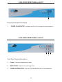
1
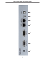
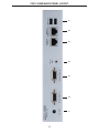
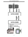
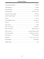
®
CAT5•1500
EXT-CAT5-1500
USER MANUAL
www.gefen.com
ASKING FOR ASSISTANCE
Technical Support:
Telephone
(818) 772-9100
(800) 545-6900
Fax
(818) 772-9120
Technical Support Hours:
8:00 AM to 5:00 PM Monday thru Friday.
Write To:
Gefen Inc.
C/O Customer Service
20600 Nordhoff St.
Chatsworth, CA 91311
www.gefen.com
[email protected]
Notice
Gefen Inc. reserves the right to make changes in the hardware, packaging and any
accompanying documentation without prior written notice.
CAT5•1500 is a trademark of Gefen Inc.
© 2009 Gefen Inc., All Rights Reserved
Rev X1
TABLE OF CONTENTS
1
Introduction
2
Box Contents
3
How it works
4
Operation Notes
5
CAT5•1500 Front Panel Layouts
6
CAT5•1500S Send Unit Back Panel
7
CAT5•1500S Back Panel Function Descriptions
8
CAT5•1500R Back Panel Layout
9
CAT5•1500R Back Panel Functions
10 CAT5 Cable Length Setup
11 Link Cable - Wiring Diagram
12 CAT5•1500 Wiring Diagram
13 System Specifications
14 Warranty
INTRODUCTION
Thank you for purchasing the new ex•tend•it CAT5•1500 series.
The ex•tend•it CAT5•1500 allows users the benefits of extending VGA, USB, and audio
signals beyond the desktop. In a growing number of applications, broadcast stations and
production facilities there is a need to control a computer remotely. The keyboard, mouse,
and video monitor are relocated to the remote side. A CPU may need to be shared between
several users or moved to another room because of annoying fan noise.
The CAT5•1500 can be used to extend computers with printers, hard drives, scanners,
cameras, keyboards, mouse, and any other USB-type devices. The CAT5•1500 has the
potential to extend the distance of 330 feet over industry standard Category 5 (CAT-5)
cable. One can connect multiple CAT5•1500 units to the same computer, allowing access
to the same computer from different locations up to 330 feet apart.
1
BOX CONTENTS
The CAT5•1500 system consists of:
(1) CAT5•1500S sender unit
(1) CAT5•1500R receiver unit
(2) 5 VDC power supply
(1) Video cable (6 FT)
(1) USB cable (6 FT)
(1) Audio cable (6 FT)
(1) User Manual
2
HOW IT WORKS
In its most basic application, the CAT5•1500S sender unit resides next to the computer. With
the supplied VGA, USB, and audio cables, they connect the computer to the CAT5•1500S
sender unit.
The CAT5•1500R receiver unit and USB peripherals are placed next to the monitor. The monitor and USB devices are connected to the CAT5•1500R in the
same way they are con nect ed to the back of the com put er (PC or Macintosh).
Industry standard Category 5 (CAT-5) cables are used to link CAT5•1500S sender and
CAT5•1500R receiver units together. The VGA signals are extended by one CAT-5 cable.
While USB and audio signals are extended with a second CAT5-cable.
3
OPERATION NOTES
READ THESE NOTES BEFORE INSTALLING
OR OPERATING THE CAT5•1500 SYSTEM
* Industry standard Category-5 (CAT-5) cables are used to link the CAT5•1500 sender
and receiver boxes together.
* When two monitors are used in the local and remote locations, the video monitors must
be a multi-resolution type. This pertains to monitors placed remotely, and those divided
between local and remote locations. The video monitors will not initialize correctly at startup if they are different types.
* The CAT5•1500 units are housed in a metal box for better RF shielding.
4
CAT5•1500S FRONT PANEL LAYOUT
1
Front Panel Function Descriptions
1
POWER ON INDICATOR - Indicates that the unit is plugged in and powered on
CAT5•1500R FRONT PANEL LAYOUT
1
2 3
Front Panel Function Descriptions
1
Focus - Fine focus adjustment for video
2
BRIGHTNESS - Adjusts the video brightness
3
POWER ON INDICATOR - The red LED indicates that the unit is powered on
5
1
2
3
4
5
6
7
CAT5•1500S SEND UNIT BACK PANEL
6
CAT5•1500S BACK PANEL FUNCTIONS
1
POWER - 5 VDC external power supply
2
MONITOR OUT - HD15 output connects to the monitor for local video
3
VIDEO IN - HD15 input from computer
4
CAT-5 VIDEO - RJ-45 input extends VGA signals with CAT-5 cable
5
CAT-5 USB/AUD - RJ-45 input extends USB, and audio signals with CAT-5 cable
6
AUDIO - Audio mini Jack input from computer
7
USB IN - USB Input from computer
7
1
2
3
4
5
6
7
CAT5•1500R BACK PANEL LAYOUT
8
CAT5•1500R BACK PANEL FUNCTIONS
1
POWER - 5 VDC external power supply
2
VIDEO OUT 1 - HD15 output connecting to the video monitor
3
VIDEO OUT 2 - HD15 output connecting to the video monitor (mirrored video)
4
AUDIO - Audio Mini Jack
5
CAT-5 VIDEO - RJ-45 input connects CAT-5 cable to receive extended VGA
signals
6
CAT-5 USB/AUD - RJ-45 input connects CAT-5 cable to receive extended USB,
and audio signals
7
2 USB OUT - USB Outputs (Type A) - Connects to USB devices
9
CAT5 CABLE LENGTH SETUP
Jumper settings are used to set the focus of the picture and characters to the best possible
sharpness. The jumpers in the CAT5•1500R are set at the factory as shown in the diagram
below. The first step to adjusting the video is to have the CAT5•1500S and CAT5•1500R
connected together with the CAT-5 cable that is going to be used in the installation. Then
set your computer to the resolution and refresh rate that you will be using most frequently
be using. Then open up the CAT5•1500R by unscrewing the bottom three screws on back
end of the box. Then two screws on each side of the box and the top. There are 9 screws
total that need to be removed. Lastly, the 4 hex bolts around the Monitor Out port and
the Video In port need to also be removed. When this is done, look at some text on the
monitor and set the jumpers to the recommended jumper setting based on the length of
your CAT-5 extension cable. If smearing is present, try moving all the jumpers up or down
one from the recommended setting. If just one color smears, adjust an individual jumper
for the color that is smearing (it can be two colors). Repeat the same steps for monitor 2
Jumper Settings
Recommended Jumper Settings
Cable length
Position
0-132 feet
4
3
2
1
133-198
Red Green Blue
199-264 feet
265-330 feet
10
11
1
8
8
7
6
5
4
3
2
1
RJ-45 Jack
Brown
White/Brown
Green
White/Blue
Blue
White/Green
Orange
White/Orange
8
7
6
5
4
3
2
1
1
8
RJ-45 Jack
LINK CABLE - WIRING DIAGRAM
CAT5•1500 WIRING DIAGRAM
12
SPECIFICATIONS
Video Amplifier Bandwidth .................................................................................. 350 MHz
Actual Bandwidth .........................................,...................................................... 120 MHz
Input Video Signal ......................................................................................... 1.2 Volts p-p
Input Sync Signal ................................................................................... 5 Volts p-p (TTL)
Horizontal Frequency Range ........................................................................... 15-70 KHz
Vertical Frequency Range .............................................................................. 30 - 170 Hz
Video In................................................................................................................... HD-15
Focus/Brightness Control ............................................................................. 25 to 330 FT
Video out ................................................................................................................ HD-15
Link Connector ........................................................................................................ RJ-45
USB - "A" Connector ........................................................................................ USB Input
USB - "B" Connector ............................................................................ USB Device Input
Audio Connector ...................................................................... mini-phone Stereo 3.5mm
Power Consumption ................................................................... 10 Watts per unit (max.)
Power Supply ......................................................................................... 5 VDC (External)
Dimensions ................................................................................. 8.4" W x 1.6" H x 4.2" D
Rack Mountable .......................................................................................... 1 Rack Space
Shipping Weight ....................................................................................................... 6 Lbs
13
WARRANTY
Gefen Inc. warrants the equipment it manufactures to be free from defects in material
and workmanship.
If equipment fails because of such defects and Gefen Inc. is notified within two
(2) year from the date of shipment, Gefen Inc. will, at its option, repair or replace
the equipment, provided that the equipment has not been subjected to mechanical,
electrical, or other abuse or modifications.
Equipment that fails under conditions other than those covered will be repaired at the
current price of parts and labor in effect at the time of repair. Such repairs are warranted
for ninety (90) days from the day of reshipment to the Buyer.
This warranty is in lieu of all other warranties expressed or implied, including without
limitation, any implied warranty or merchantability or fitness for any particular purpose,
all of which are expressly disclaimed.
1. Proof of sale may be required in order to claim warranty.
2. Customers outside the US are responsible for shipping charges to and from Gefen.
3. Copper cables are limited to a 30 day warranty and cable must be free from any
scratches, markings, and neatly coiled.
The information in this manual has been carefully checked and is believed to be
accurate. However, Gefen Inc. assumes no responsibility for any inaccuracies that may
be contained in this manual. In no event will Gefen Inc., be liable for direct, indirect,
special, incidental, or consequential damages resulting from any defect or omission
in this manual, even if advised of the possibility of such damages. The technical
information contained herein regarding CAT5•1500 features and specifications is subject
to change without notice.
For the latest warranty coverage information, please visit Gefen’s Warranty web page at
http://www.gefen.com/kvm/aboutus/warranty.jsp
PRODUCT REGISTRATION
Please register your product online by visiting Gefen’s web site at
http://www.gefen.com/kvm/Registry/Registration.jsp
14
*MA-cat5-1500*
Rev X1
20600 Nordhoff St Chatsworth, CA 91311
1-800-545-6900 818-772-9100 fax: 818-772-9120
www.gefen.com
Pb
[email protected]