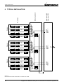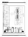
1
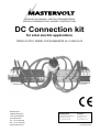
INSTALLATION MANUAL / INSTALLATIEHANDLEIDING
INSTALLATIONSANLEITING / MANUEL D’INSTALLATION
DC Connection kit
for solar electric applications
TRIPLE OUTPUT MODEL FOR SUNMASTER XL-10 AND XL15
MASTERVOLT
Snijdersbergweg 93,
1105 AN Amsterdam
The Netherlands
Tel.: +31-20-3422100
Fax.: +31-20-6971006
www.mastervolt.com
ENGLISH:
NEDERLANDS:
DEUTSCH:
FRANÇAIS:
PAGE 1
PAGINA 13
SEITE 25
PAGINA 37
v 2.0 January 2011
TABLE OF CONTENTS
Copyright © 2011 Mastervolt. All rights reserved.
Reproduction, transfer, distribution or storage of part or all of the contents in this document in any form without the prior written
permission of Mastervolt is prohibited.
TABLE OF CONTENTS:
v 2.0 January 2011
1
GENERAL INFORMATION.............................................................................................................................................. 3
1.1
Product description............................................................................................................................................. 3
1.2
Use of this manual.............................................................................................................................................. 3
1.3
Validity of this manual ........................................................................................................................................ 3
1.4
Guarantee specifications .................................................................................................................................... 3
1.5
Liability ............................................................................................................................................................... 3
1.6
Changes to the DC Connection kit ..................................................................................................................... 3
1.7
Identification label............................................................................................................................................... 3
2
SAFETY GUIDELINES AND WARNINGS....................................................................................................................... 4
2.1
Warnings and symbols ....................................................................................................................................... 4
2.2
Use for intended purpose ................................................................................................................................... 4
2.3
Organisational measures ................................................................................................................................... 4
2.4
Installation, maintenance and repair................................................................................................................... 4
2.5
Warning of special dangers ................................................................................................................................ 4
3
SPECIFICATIONS ........................................................................................................................................................... 5
3.1
Technical specifications ..................................................................................................................................... 5
3.2
Outline drawings................................................................................................................................................. 5
4
INSTALLATION ............................................................................................................................................................... 6
4.1
General .............................................................................................................................................................. 6
4.2
Unpacking .......................................................................................................................................................... 6
4.3
Installation environment ..................................................................................................................................... 6
4.4
PV modules and strings ..................................................................................................................................... 6
4.5
Use of the spring-cage terminals........................................................................................................................ 6
4.6
Wiring instructions .............................................................................................................................................. 7
4.6.1
Things you need: ............................................................................................................................... 7
4.6.2
Wiring between PV-modules and the DC Connection kit................................................................... 7
4.6.3
Wiring between the DC Connection kit and inverter .......................................................................... 7
4.6.4
Connection to the safety ground (PE)................................................................................................ 7
5
START-UP AFTER INSTALLATION ............................................................................................................................... 9
5.1
Commissioning................................................................................................................................................... 9
5.2
Decommissioning ............................................................................................................................................... 9
5.3
Maintenance....................................................................................................................................................... 9
6
TYPICAL INSTALLATION............................................................................................................................................. 10
7
SCHEMATICS................................................................................................................................................................ 11
8
EC DECLARATION OF CONFORMITY ........................................................................................................................ 12
2
Copyright © 2011 Mastervolt / January 2011 / DC Connection kit for solar electric applications / EN
GENERAL INFORMATION
1 GENERAL INFORMATION
1.1
PRODUCT DESCRIPTION
The Mastervolt DC Connection kit for solar electric
applications is a DC switch between photovoltaic modules
and the Solar inverter on buildings, as required by the
international standard IEC60364-7-712. In this manual it
will be mentioned as “DC Connection kit”.
1.2
USE OF THIS MANUAL
This manual serves as a guideline for the safe and
effective installation of the Mastervolt DC Connection kit:
• The electrician will find in this manual directions for the
installation, operation and commissioning.
• The end-user finds directions for the operation,
maintenance and possible correction of minor
malfunctions of the DC Connection kit.
• Both the installer and the end-user must be completely
familiar with the contents of this manual, and must
carefully follow the instructions contained herein.
• The manual must be accessible to the user
immediately.
This English manual has 12 pages.
1.3
VALIDITY OF THIS MANUAL
All of the specifications, provisions and instructions
contained in this manual apply to standard versions of the
DC Connection kit delivered by Mastervolt solely.
This manual is valid for the following models:
Part number
130506000
1.4
Description
XL connection kit +DC-switch 600V
30A 6p
GUARANTEE SPECIFICATIONS
Mastervolt assures the product guarantee of the DC
Connection kit during two years after your purchase, on
the condition that all instructions and warnings given in this
manual are taken into account during installation and
operation.
Among other things, this means that installation is done by
a qualified electrician, that installation and maintenance
are executed according to the stated instructions and
correct working sequence and that no changes or repairs
may have been executed on the DC Connection kit other
than by Mastervolt.
The guarantee is limited to the costs of repair and/or
replacement of the product by Mastervolt only. Costs for
installation labour or shipping of the defective parts are not
covered by this warranty.
For making an appeal on guarantee you can directly
contact your supplier, mentioning your complaint,
application, date of purchase and part number / serial
number.
1.5
LIABILITY
Mastervolt can accept no liability for:
• consequential damage due to use of the DC
Connection kit;
• possible errors in the manuals and the results thereof.
• loss of energy revenues due to possible defects
1.6
CHANGES TO THE DC CONNECTION KIT
Changes on the DC Connection kit may be carried out
only after the written permission of Mastervolt.
1.7
IDENTIFICATION LABEL
Important technical information required for service,
maintenance & secondary delivery of parts can be derived
from the type number indication plate and may therefore
not be removed!
CAUTION!
Never remove the identification label.
EN / DC Connection kit for solar electric applications / January 2011 / Copyright © 2011 Mastervolt
3
SAFETY GUIDELINES AND WARNINGS
2 SAFETY GUIDELINES AND WARNINGS
2.1
WARNINGS AND SYMBOLS
2.3
Safety instructions and warnings are marked in this
manual by the following pictograms:
A procedure, circumstance,
deserves extra attention.
etc
which
CAUTION!
and
WARNING
A WARNING refers to possible injury to the
user or installer or significant material damage
to the DC Connection kit if the installer / user
does not (carefully) follow the stated
procedures.
2.2
The installer / user must always:
• have access to this manual;
• be familiar with the contents of this manual. This
applies to Chapter 2, Safety Guidelines & Warning
particularly.
2.4
Special
information,
commands
prohibitions in order to prevent damage.
ORGANISATIONAL MEASURES
INSTALLATION,
REPAIR
MAINTENANCE
AND
As lethal voltages exist, allow installation, maintenance
and repair of the DC Connection kit and changes in your
electrical system to be carried out by qualified electricians
only.
Connections and safety features must be executed
according to the locally applicable regulations.
In case of decommissioning and/or demounting follow the
instructions as stated in section 5.2.
If such are required, use only original spare parts.
USE FOR INTENDED PURPOSE
The DC Connection kit is constructed as per the applicable
safety-technical guidelines. Use the DC Connection kit
only in installations that meet the following qualifications:
• in permanent installations;
• in a closed cabinet, protected against rain, moist, dust
and condensation;
• the electrical installation must meet the applicable
regulations and standards, must be carried out
correctly and must be in a good condition;
• installed according to the instructions stated in this
manual;
• according to the technical specifications as stated in
chapter 3.
WARNING
Never use the DC Connection kit in situations
where there is danger of gas or dust explosion
or potentially flammable products!
2.5
•
•
•
•
•
WARNING OF SPECIAL DANGERS
High voltages up to 600V DC may exist. Therefore the
DC Connection kit may only be accessible for qualified
electricians.
Voltages present at the cabling to the photovoltaic
modules are not safe to touch and cannot be switched
off.
Do not work on the DC Connection kit and/or the
electrical installation if it is still connected to the solar
panels and/or the inverter.
Only allow changes in your electrical system to be
carried out by qualified electricians.
Check the wiring at least once a year. In case of loose
connections, burned cables etc: switch off the AC-grid
immediately. Defects must be corrected immediately
by a qualified electrician.
Use of the DC Connection kit other than as mentioned in
this section is not considered to be consistent with the
intended purpose. Mastervolt is not liable for any damage
resulting from the above.
4
Copyright © 2011 Mastervolt / January 2011 / DC Connection kit for solar electric applications / EN
SPECIFICATIONS
3 SPECIFICATIONS
3.1
TECHNICAL SPECIFICATIONS
Model
DC Connection kit for solar electric applications
Article no.
Configuation and Power Rating
Over voltage protection:
130506000
4 x 2 pole; 600V / 30A
Yes, by means of varistors
Type: Overvoltage arrester, 1-pole, Plug-in P-VMS 600
Max. operating voltage: 600 V AC / 50 Hz
Nominal discharge current: 20 kA (8/20)
Maximum discharge current: 40 kA (8/20)
Protection level Up: < 2,3 kV
Pröpster order nr.:206 602 (see www.proepster.com)
3 inputs with each 4 string connections (add fuses needed for > 3 strings)
3 output connections to inverter
Din Rail
–20°C up to +70°C
6mm²
94 x 390 x 185 mm (see figure 1)
Approx. 2.2 kg
Sunmaster XL-10
Sunmaster XL-15
Connections
Mounting
Ambient condition
Max wire diameter
Dimensions (HxWxD)
Weight
Applications
3.2
OUTLINE DRAWINGS
DEPTH: 195mm
Dimensions are in mm
Figure 1: DC Connection kit for solar electric applications
EN / DC Connection kit for solar electric applications / January 2011 / Copyright © 2011 Mastervolt
5
INSTALLATION
4 INSTALLATION
4.1
GENERAL
4.5
During installation and commissioning of the DC
Connection kit, the Safety Guidelines & Measures are
applicable at all times (see chapter 2 of this manual), as
well as:
• DIN VDE 0100 (Low-voltage electrical installations);
• IEC60364-7-712 (Electrical installations of buildings –
Requirements for special installations or locations Solar Photovoltaic power supply Systems);
• VDI 6012 (Local energy systems in buildings –
Photovoltaics);
• BGV A1 (General regulations);
• BGV A2 (Electrical installations and equipment).
4.2
USE OF THE SPRING-CAGE TERMINALS
The DC Connection kit is equipped with spring-cage
terminal to connect the DC-wiring. Use a maximum wire
diameter of 10mm² to fix to the DC spring-cage
connections. Strip the cable insulation 10mm.
Use an insulated 4mm flat blade screwdriver to open the
spring-cage clamp. See figure 2.
1
Push screwdriver firmly into the
indicated slot
2
Place cable into opening
3
Pull back screwdriver
UNPACKING
In addition to the DC Connection kit the delivery includes:
• this installation manual.
After unpacking, check the contents for possible damage.
Do not use the product if is damaged. If in doubt, contact
your supplier.
4.3
INSTALLATION ENVIRONMENT
The DC Connection kit must be installed in the vicinity of
the solar inverter, in a closed cabinet, protected against
rain, moist, dust and condensation.
4.4
PV MODULES AND STRINGS
The solar or DC side of the system consists of several
photovoltaic (solar) modules, further mentioned as “PV
modules”. The PV-modules are connected in series to
form a so called “string”. These strings consist of a positive
(+) and a negatiev (–) connection which can be connected
directly to the DC Connection kit.
The string voltage should be equal to the open circuit
voltage (Voc) per PV module (refer to the specifications of
the PV-module), multiplied by the number of PV-modules
in each string. Depending on the solar irradiation, this
value should be equal to 70-95% of the calculated string
voltage.
Figure 2: Use of the spring-cage terminals
6
Copyright © 2011 Mastervolt / January 2011 / DC Connection kit for solar electric applications / EN
INSTALLATION
4.6
WIRING INSTRUCTIONS
WARNING
High voltages (up to 600 VDC) may exist on
the PV-strings! Connection of the DC-cabling
may only be carried out if the DC-cables are
voltage free. Therefore the PV-modules must
be disconnected from the DC-cabling (for
instance by disconnecting the MultiContact
connectors at the PV-modules).
4.6.1
4.6.2
CAUTION!
•
•
•
•
•
•
Short circuiting, reversing polarity or
interchanging of PV-strings may lead to
damage to the DC Connection kit, the
Solar inverter, the cabling and/or the
terminal connections.
The maximum output current may not
exceed 30A for each output of the DCSwitch.
If two ore more strings are connected to
the same Solar-input, both string lengths
must be equal.
Follow all steps of the installation
instructions in order of succession as
described.
During the entire installation the rotary
switch of the DC Connection kit must stay
in the O-position (OFF).
Do not change the existing wiring of the
DC Connection kit
Refer to chapter 6 for typical installation
examples.
Things you need:
To connect the DC Connection kit to the inverter you need
the following cables, long enough to reach from the DC
Connection kit to the inverter (not included with the
delivery)
• Three double isolated DC cables with positive (+)
marking (e.g. red colour) ,
• Three double isolated DC cables with negative (–)
marking (e.g. black colour)
Wiring between PV-modules and the DC
Connection kit
See figure 3. First make the connections to INPUT 1, and
then make the connections to INPUT 2, followed by INPUT
3.
1
2
3
Turn the rotary switch of the DC Connection kit to the
O-position (OFF).
Mount the DC Connection kit in a closed cabinet.
Strip approx. 10 mm of the DC-cables and connect
the cables as indicated.
4.6.3
Wiring between the DC Connection kit
and inverter
See figure 3. Follow in detail all steps of the installation
instructions in order of succession as described below.
1
2
3
4
5
<<<< TEXT REMOVED >>>>
6
Make sure the rotary switch of the DC Connection kit
is still set to the O-position (OFF).
Strip approx. 10 mm on both sides of the DC cables
Connect the DC cable with positive marking (+)
between the positive (+) connection of the OUTPUT
and the positive (+) DC Solar input of the inverter.
Repeat this for the negative (–) connection.
Repeat steps 3 and 4 to connect the OUTPUT 2 to
DC Solar input nr. 2 of the inverter.
Repeat steps 3 and 4 to connect the OUTPUT 3 to
DC Solar input nr. 3 of the inverter.
4.6.4
Connection to the safety ground (PE)
See figure 3. Connect the earth terminals of the varistors
to the safety ground (PE) as indicated. The wiring of this
connection should have a minimum cross section of 16
mm².
EN / DC Connection kit for solar electric applications / January 2011 / Copyright © 2011 Mastervolt
7
PE
INSTALLATION
– VARISTOR 3
– VARISTOR 2
– VARISTOR 1
– INPUT 3
– INPUT 3
– INPUT 3
– INPUT 3
– INPUT 1
– INPUT 2
– INPUT 2
1 (ON)
– OUTPUT 3
– INPUT 2
– OUTPUT 2
– INPUT 1
– INPUT 1
– INPUT 1
– INPUT 1
0 (OFF)
+ OUTPUT 3
ROTARY SWITCH POSITIONS:
TOP
– OUTPUT 1
+ INPUT 3
+ INPUT 3
+ INPUT 3
+ INPUT 3
+ INPUT 2
+ INPUT 2
+ INPUT 2
+ INPUT 2
+ OUTPUT 1
+ INPUT 1
+ INPUT 1
+ INPUT 1
+ INPUT 1
+ VARISTOR 3
+ VARISTOR 2
PE
+ VARISTOR 1
8
Figure 3: Connections of the DC-Connection kit:
+ OUTPUT 2
Copyright © 2011 Mastervolt / January 2011 / DC Connection kit for solar electric applications / EN
START-UP AFTER INSTALLATION
5 START-UP AFTER INSTALLATION
5.1
COMMISSIONING
CAUTION!
Check the polarity of all wiring before
commissioning: positive connected to positive,
negative connected to negative.
Follow the steps described below to switch on the DC
Switch of the DC Connection kit.
5.2
If it is necessary to put the DC Connection kit out of
operation, follow the instructions in order of succession as
described below:
1
2
3
1
2
3
4
5
Connect the PV-modules to the DC-cabling (for
instance by connecting the MultiContact connectors of
the string cabling).
Check the voltage and polarity of all connections with
a suitable DC voltage meter. This voltage should be
equal to the open circuit voltage (Voc) per PV module
(refer to the specifications of the modules), multiplied
by the number of modules in each string. Depending
on the irradiation of the PV module, the measured
value should be equal to 70-95% of the theoretically
calculated value. Make sure that the measured
voltage matches the specifications the DC-input of the
inverter.
If the voltage and polarity of the strings is OK, turn the
rotary switch of the DC Connection kit to the 1postion.
Check whether the DC voltage is present at the
inverter (refer to the user’s manuals of the inverter).
Connect the solar inverter to the electric grid (refer to
the user manual of the solar inverter).
DECOMMISSIONING
4
Disconnect the solar inverter form the electric grid
(refer to the user manual of the solar inverter).
Turn the rotary switch of the DC Connection kit to the
O-position (OFF).
Disconnect the PV-modules from the DC-cabling (for
instance
by
disconnecting
the
MultiContact
connectors at the PV-modules).
Remove the DC-cables one by one by opening the
spring cage clamps (see figure 3). Insulate the loose
wire end of each DC cable with insulating tape.
Now the DC Connection kit can be demounted in a safe
way.
5.3
MAINTENANCE
The operation of the varistors must be checked regularly.
Varistors indicating a red window must be exchanged by
an identical type (see section 3.1 for specifications).
EN / DC Connection kit for solar electric applications / January 2011 / Copyright © 2011 Mastervolt
9
TYPICAL INSTALLATION
Sunmaster XL10
Sunmaster XL15
AC
SOLAR
INPUT 1
Optional
SOLAR
INPUT 2
Optional
SOLAR
INPUT 3
Optional
PV-strings
DC Connection kit
6 TYPICAL INSTALLATION
Figure 4
DC Connection kit with Sunmaster XL-10kW or XL-15kW
10
Copyright © 2011 Mastervolt / January 2011 / DC Connection kit for solar electric applications / EN
SCHEMATICS
7 SCHEMATICS
A
1
3
5
6
B
D
F
E
C
4
2
Figure 5
EN / DC Connection kit for solar electric applications / January 2011 / Copyright © 2011 Mastervolt
11
EC DECLARATION OF CONFORMITY
8 EC DECLARATION OF CONFORMITY
Manufacturer
Address
Mastervolt
Snijdersbergweg 93
1105 AN Amsterdam
The Netherlands
Herewith declares that:
Product:
130506000
DC Connection kit for solar electric applications
is produced in conformity with the following standards:
IEC 60947-1 and 3
EN 60947-1 and 3
DIN VDE 0660 Part 107
and complies with the provisions of EU Council Directives
•
•
•
2002/95/EG (ROHS Directive on the Restriction of the Use of Certain Hazardous Substances in Electrical and Electronic
Equipment)
2002/96/EG from 27.01.2003 (The Directive on Waste Electrical and Electronic Equipment)
Directive 2006/95/EC of the European Parliament and of the Council of 12 December 2006 on the harmonisation of the
laws of Member States relating to Electrical Equipment designed for use with certain voltage limits
Additional information:
This product is intended to be installed, maintained and used by professional or entitled persons.
Amsterdam,
P.F. Kenninck,
CEO MASTERVOLT
Snijdersbergweg 93, 1105 AN Amsterdam, The Netherlands
Tel : + 31-20-3422100
Fax : + 31-20-6971006
Email : [email protected]