1
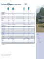
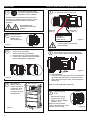
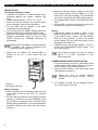
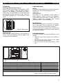
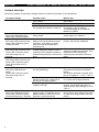
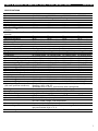
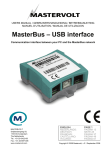
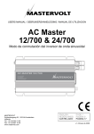
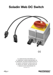
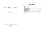
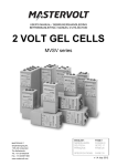
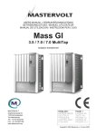
Master series
Qualitative battery chargers,
inverters and converters
Lightweight
High efficiency
Easy to install
Power you
can rely on
Specifications AC Master sine wave inverters
- 230 V
HR geplaatst. Op
dit formaat kan de
kwaliteit er nog wel
mee door.
AC Master
AC Master
AC Master
AC Master
12/300
12/500
24/300
24/500
Article no. 230 V (universal socket)
28010300
28010500
28020300
28020500
Nominal battery voltage
12 V
12 V
24 V
24 V
Recommended battery capacity
≥60 Ah
≥100 Ah
≥30 Ah
≥50 Ah
Output voltage (± 5%)
230 V – 50 Hz (± 0.1%)
230 V – 50 Hz (± 0.1%)
230 V – 50 Hz (± 0.1%)
230 V – 50 Hz (± 0.1%)
Continuous power at 25 °C, cos phi 1
300 W
500 W
300 W
500 W
Continuous power at 40 °C, cos phi 1 250 W
400 W
250 W
400 W
Peak load
600 W
800 W
600 W
800 W
Output waveform
true sine
true sine
true sine
true sine
Efficiency
90%
90%
91%
91%
Display/read out
LED display
LED display
LED display
LED display
Dimensions, hxwxd
210x130x60 mm
210x130x60 mm
210x130x60 mm
210x130x60 mm
8.3x5.1x2.4 inch
8.3x5.1x2.4 inch
8.3x5.1x2.4 inch
8.3x5.1x2.4 inch
Weight
1,16 kg
1,22 kg
1,16 kg
1,22 kg
2.55 lbs
2.69 lbs
2.55 lbs
2.69 lbs
Approvals
CE, E-mark, ABYC A-31
CE, E-mark, ABYC A-31
GENERAL SPECIFICATIONS
CE, E-mark, ABYC A-31
CE, E-mark, ABYC A-31
TECHNICAL SPECIFICATIONS
Technology
HF switch mode
HF switch mode
Low battery voltage, switches off at
10 V, ± 0,5 V
10 V, ± 0,5 V
HF switch mode
HF switch mode
20 V, ± 0,5 V
20 V, ± 0,5 V
Low battery voltage, switches on at
11 V, ± 0,5 V
11 V, ± 0,5 V
22 V, ± 0,5 V
22 V, ± 0,5 V
High battery voltage, switches off at
16 V, ± 0,5 V
16 V, ± 0,5 V
32 V, ± 0,5 V
32 V, ± 0,5 V
14,5 V, ± 0,5 V
14,5 V, ± 0,5 V
29 V, ± 0,5 V
29 V, ± 0,5 V
Max. ripple on DC (battery)
High battery voltage, switches on at
10% RMS
10% RMS
10% RMS
10% RMS
Input current (nominal load)
22,5 A
37,5 A
11 A
19 A
No load power consumption:
• on’ mode (230 V)
0,58 A – 7 W
0,58 A – 7 W
0,29 A – 7 W
0,29 A – 7 W
• standby (scan mode)
0,33 A – 4 W
0,33 A – 4 W
0,16 A – 4 W
0,16 A – 4 W
Minimal DC fuse (slow blow)**
40 A
80 A
20 A
40 A
Minimal cable size
included
included
included
included
Harmonic distortion typical
< 6%
< 6%
< 6%
Cos Phi
all power factors allowed Temperature range (ambient temp.)
< 6%
-25 °C to 60 °C, > 25 °C derating power
-25 °C to 60 °C, > 25 °C derating power
natural/forced
natural/forced
natural/forced
natural/forced
Sound level 53 dBA at 1 mtr
53 dBA at 1 mtr
53 dBA at 1 mtr
53 dBA at 1 mtr
Protection degree
IP23
IP23
IP23
IP23
Protections
over temperature, over load, short circuit, high battery, low battery
over temperature, over load, short circuit, high battery, low battery
MasterBus compatibel
no
no
no
no
AC connection
universal
universal
universal
universal
See www.mastervolt.com/inverters for detailed specifications,
dimension drawings, 3D files, certificates and manuals.
• Silent.
all power factors allowed
Cooling
** DC fuse depends on the cable size.
Benefits
• Small & lightweight.
• Universal plug.
• Designed for recreational
and semi-professional use.
USERS MANUAL / GEBRUIKERSHANDLEIDING
BETRIEBSANLEITUNG / MANUEL D’UTILISATION
MANUAL DE UTILIZACION / INSTRUZIONI PER L’USO
AC Master
12/300, 12/500, 24/300, 24/500
Switch mode sine wave inverter
MASTERVOLT
Snijdersbergweg 93,
1105 AN Amsterdam
The Netherlands
Tel.: +31-20-342 21 00
Fax: +31-20-697 10 06
www.mastervolt.com
ENGLISH:
NEDERLANDS:
DEUTSCH
FRANÇAIS
CASTELLANO:
ITALIANO
PAGE 1
PAGINA 9
SEITE 17
PAGINA 25
PÁGINA 33
PAGINA 41
Copyright © 2009 Mastervolt, v 1.3 November 2009
ENGLISH
QUICK INSTALLATION INSTRUCTIONS
This section provides a brief
overview of a basic stand alone
installation of the AC Master
1
5
Connect the battery to the DC input.
Do not place the DC fuse(s) yet.
However; please review the entire manual for
connection of additional features and to ensure
best performance and years of trouble-free
operation.
Use isolated tools!
Read safety instructions
(page 3).
Grounding wire
Red wire:
POS (+)
2
Move the main
switch of the AC
Master to the
OFF position (0).
Connect
red wire to +,
black wire to –.
Disconnect the electrical power:
• Switch off all consumers,
• Switch off all charging systems.
• Remove the fuse cover and DC fuse(s).
• Check with a suitable voltmeter whether
the DC installation is voltage free.
Figure 4
Incorrect polarity will damage
the AC Master!
Figure 1
3
Black wire:
NEG (–)
6
The AC load can be connected directly to
the AC socket. Different plugs are possible.
Figure 5
Figure 2
4
Mount the AC
Master with four
screws vertically to
a solid wall. Allow
at least 10 cm / 4
inch space around
the apparatus!
Figure 3
2
For safe installation:
• Connect the grounding point of the AC Master to
the central grounding point of the vehicle/ ship.
• When disconnecting AC load, switch Off the AC
Master first.
Refer to locally applicable regulations.
7
Check all wiring.
If OK:
• Place the DC fuse(s).
• Close the fuse cover
• Switch on the AC Master
(position I or II).
When the fuse is placed,
internal capacitors may cause
a spark. This is normal.
Figure 6
USER’S MANUAL AC MASTER 12/300, 12/500, 24/300, 24/500
VALIDITY OF THIS MANUAL
Copyright © 2009 Mastervolt. All rights reserved.
Reproduction, transfer, distribution or storage of
part or all of the contents in this document in any
form without the prior written permission of
Mastervolt is prohibited.
This manual is valid for the following models:
Model
Part number
AC Master 12/300
28010300
AC Master 12/500
28010500
AC Master 24/300
28020300
AC Master 24/500
28020500
From now on, these models will be referred to as
“AC Master”.
PRODUCT DESCRIPTION AND APPLICATION
The Mastervolt inverter AC Master converts a DC
voltage to a pure AC sine wave voltage.
Typical applications (300W or 500W max,
depending on AC Master model) are shown below.
• In the household: lamp, fans, sewing machines.
• For office equipment: computers, printers,
monitors, scanner.
• For home entertainment electronics: television,
DVD recorders, CD players, video games,
musical instruments, audio equipment.
• Electrical tools: drilling machines, grinding
machines, circular saws.
SAFETY INSTRUCTIONS
WARNING!
Before using the AC Master, read and
save the Safety Instructions.
Make sure the total power of all
connected devices is within the limits!
• Use the AC Master according to the instructions
and specifications stated in this manual.
• Connections and safety features must be
executed according to the locally applicable
regulations.
• Operation of the AC Master without proper
grounding may lead to hazardous situations!
• If the positive and negative wires on the DCinput (battery) are reversed, the AC Master will
be damaged. Damage of this kind is not covered
by guarantee. Check whether all connections
are correct before placing the fuse(s).
• Do not connect the AC output of the inverter to
an incoming AC source or generator.
• Never connect the AC Master in parallel with
any other inverter.
• Never open the housing as high voltages may
be present inside!
DC input cables (1.5 m)
Positive
Negative
Main switch
ENGLISH
PE/
Ground
AC
output
F
U
S
E
Fuse holder
Grounding point
Figure 7: Overview connections
UNPACKING
The delivery consists of the following parts:
• The AC Master
• This user’s manual
• 1.5 m/ 5 ft DC input battery cable
• 1 or 2 (see specifications) blade fuses 40 A
After unpacking, check the AC Master for possible
damage. Do not use the AC Master if it is
damaged. If in doubt, contact your supplier.
GUARANTEE TERMS
Mastervolt guarantees that this product was built
according to the legally applicable standards and
stipulations. If you fail to act in accordance with the
regulations and instructions in this user’s manual,
damage will occur and/ or the product will not fulfil
the specifications. This may mean that the
guarantee will become null and void. The
guarantee is limited to the costs of repair and/ or
replacement of the product by Mastervolt only.
Costs for installation labour or shipping of the
defective parts are not covered by this guarantee.
For making an appeal on warranty you can directly
contact your supplier, mentioning your complaint,
application, date of purchase and part number /
serial number. The standard guarantee period for
this product is 2 years.
LIABILITY
Mastervolt cannot be held liable for:
• Possible errors in this manual and their
consequences.
• Use of this product that is inconsistent with its
purpose.
3
ENGLISH
USER’S MANUAL AC MASTER 12/300, 12/500, 24/300, 24/500
INSTALLATION
Choosing a location to install
• Install the AC Master in a well-ventilated room
protected against rain, vapour, moisture and
dust.
• Ambient temperature: 0 - 40°C / 32 - 104°F.
• Never use the AC Master at a location where
there is danger of gas or dust explosions.
• Do not install the AC Master in the same
compartment as the batteries.
• Do not mount the AC Master straight above the
batteries because of possible corrosive fumes.
• Mount the AC Master vertically with the cables
hanging downwards (figure 8) and so that
airflow through the ventilation openings is
guaranteed.
• Make sure that the battery voltage is the same
as the input voltage of the AC Master (e.g. 24V
battery for a 24V input voltage). Also check that
your loads comply with the 230V output voltage.
• The integrated DC fuse(s) should be placed last
of all.
• Use four Ø4.5 mm (No. 8) screws to mount the
AC Master to a solid surface (figure 8).
Mounting the AC Master in another position
is possible, this however influences the
ingress protection degree (IP).
Wiring
• Connect DC wiring as shown in figure 4: the
black terminal NEG (–) to the negative (–) pole
of the power source / battery, the red terminal
POS (+) to the positive (+) pole of the power
source/ battery. Do not place the fuse(s) in the
integrated fuse holder yet.
• Chassis ground: Use a cable AWG8 / 6 mm² to
connect the GROUNDING POINT (figure 7) to
the central ground.
• Make sure no objects are located within a
distance of 10 cm / 4 inch around the AC
Master.
The neutral connector N of the AC output
(figure 7) is NOT connected to the
Grounding point!
COMMISSIONING AFTER INSTALLATION
1. Check the polarity of the DC connections: Red
cable positive, black cable negative. Only place
the DC fuse(s) if the polarity is correct.
2. Place the DC-fuse(s) in the fuse holder (see
Specifications on page 7).
When the fuse is placed, internal
capacitors may cause a spark. This is
normal.
Figure 8:
Mounting to the wall
Before you start
• Before installing the AC Master make sure the
main switch is set to the OFF (“0”) position
(figure 1).
• Be sure that the output of the supplying source
(battery) is switched off during installation. Also
be sure that no consumers are connected to the
battery during installation, to prevent hazardous
situations. Remove the fuse cover and fuse(s)
(figure 2).
4
3. AC voltage: the load can be plugged into the
AC output (figure 7) directly.
USER’S MANUAL AC MASTER 12/300, 12/500, 24/300, 24/500
OPERATION
Switching ON and Power Saving
Move the main switch (figure 9) to position I (“ON”)
or II (“Power saving”). With the power switch in
position II, the battery is saved when the load is
under 40 W. The AC Master is in scan mode then
and switches on when it detects a load. When the
AC Master switches on, it will produce a short
beep.
Switching OFF
Move the main switch (figure 9) to the position O
(“OFF”). Note that switching off the AC Master does
not disconnect the batteries!
Sine wave LED
Continuous (green)
Blinking (green)
Continuous (red)
Blinking slowly (red)
Blinking fast (red)
Off
USER INTERFACE
Alarms
Four beep modes distinguish the alarm modes and
switching on. See Trouble shooting for more
information.
LED indicators
See figure 10. The operation of the inverter is
made visible by means of three LED indicators:
Output LED, Sine wave LED and Power LED. Five
different stages are indicated. See Trouble
shooting section for more information.
MAINTENANCE
No specific maintenance is required. If necessary,
use a soft clean cloth to clean the AC Master.
Never use any liquids, acids and/ or scourers.
Check the wiring on a regular base. Defects such
as loose connections, burnt wiring etcetera must be
corrected immediately.
Figure 9: Main switch
Output LED
Continuous (green)
Blinking (green)
Off
Off
Off
Off
ENGLISH
DECOMMISSIONING
Proceed as follows for decommissioning of the
inverter:
1. Move the main switch (figure 9) to position 0
(“OFF”).
2. Remove the DC fuse(s). Be sure that others
can not reverse this action taken.
3. Now the inverter can be demounted in a safe
way.
Power LED
Continuous (green)
Continuous (green)
Continuous (green)
Continuous (green)
Continuous (green)
Off
Stage
Inverter OK
Power saving
Inverter fault
Battery voltage low/ high
Short circuit
Inverter off
Figure 10: Display LEDs and their function
5
ENGLISH
USER’S MANUAL AC MASTER 12/300, 12/500, 24/300, 24/500
TROUBLE SHOOTING
Consult an installer, if the output voltage cannot be retrieved by means of the table below.
No output voltage
All LED indicators are off.
Possible cause
Main switch (figure 9) is set to the
OFF position.
DC fuse(s) blown
AC feedback, feedback protection
has caused the inverter to switch off.
Output LED blinks green,
Sine wave LED blinks green,
Power LED continuous green.
Output LED off,
Sine wave LED continuous red,
Power LED continuous green,
Continuous beep.
Power saving: Inverter is in Power
saving mode.
Output LED off,
Sine wave LED continuous red,
Power LED continuous green,
One short beep every 2
seconds.
Output LED off,
Sine wave LED continuous red,
Power LED continuous green,
Three short beeps every 2
seconds.
Output LED off,
Sine wave LED blinks red
slowly,
Power LED continuous green,
One short beep every 2
seconds.
Output LED off,
Sine wave LED blinks red fast,
Power LED continuous green,
one short beep every 2 seconds.
6
Inverter fault: Over temperature
Reduce the load and let the inverter
cool down. It will switch on again
when the internal temperature is
sufficiently low.
Inverter fault: Overload.
Inverter attempts a restart 5 times. If
it still fails, the AC Master remains in
Overload and produces a continuous
beep.
Inverter fault: Fan fault.
Battery voltage low: DC input voltage
too low (flat battery).
DC input voltage too low: voltage
drops across the DC cables due to
too long or too narrow cables.
Battery voltage high: DC input
voltage is too high.
Short circuit. Inverter attempts a
restart 5 times. If it still fails, the AC
Master remains in Short circuit and
produces a continuous beep.
What to do?
Put the main switch (figure 9) in the
ON position.
Replace the fuse(s).
Take away the extra AC power source
and switch on the AC Master.
To avoid damage do not install AC
Masters in parallel.
Increase the load or put the main
switch (figure 9) in position I.
Check the airflow through the
inverter. See section Installation.
Reduce the load and/ or check the AC
wiring for possible short circuits. Then
reset the inverter manually by
switching the main switch off and on
again.
Contact your Mastervolt supplier.
Check the battery. At low voltage,
disconnect the load and charge the
battery.
The inverter will switch on again when
the input voltage is > 11.0 V / >22.0 V.
Reduce the length of the DC cables or
use cables with a larger diameter.
Check battery voltage; switch off
charger. The inverter will switch on
again when the input voltage is <14.5 /
<29.0 V.
Switch off the AC Master and check
the AC wiring. Only switch the inverter
on when the wiring problem has been
solved.
USER’S MANUAL AC MASTER 12/300, 12/500, 24/300, 24/500
ENGLISH
SPECIFICATIONS
Model AC Master
12/300-230V EU
Part number:
Function
Supplier:
General
Nominal battery voltage
Input voltage:
Nom Power Tamb=25°C,
cos phi=1
Max. peak load during 5
seconds
Output waveform
Maximum efficiency
Output voltage
Frequency
Harmonic distortion typical
AC connection
Dimensions (HxWxD)
Weight:
Technical
Technology
Shut down voltage low battery
Restart voltage low battery
Shut down voltage high battery
Restart voltage high battery
Maximum allowed ripple on DC
Input current @ nominal load
DC fuse required (slow blow)
Minimum battery capacity:
DC cable for battery connection:
No load power consumption:
Off mode
On mode @ save mode
On mode @ high mode
Operating temperature specified
(will meet specified tolerances)
28010300
28010500
28020300
Conversion of a DC voltage to an AC voltage.
Mastervolt, Amsterdam, the Netherlands.
28020500
12V
10 - 15.5 V
300 VA
12V
10 - 15.5 V
500 VA
24V
20 - 32 V
300 VA
24V
20 - 32 V
500 VA
600 VA
800 VA
600 VA
800 VA
Cooling:
Storage temperature
Relative humidity
Standards and approvals
Vibration and shock levels
Protections
Reversed polarity protection
Power saving
Protection degree
12/500-230V EU
24/300-230V EU
24/500-230V EU
True sine
True sine
True sine
90 %
90 %
91 %
230 V +/- 5 %
230 V +/- 5 %
230 V +/- 5 %
50 Hz +/- 0.1 % 50 Hz +/- 0.1 % 50 Hz +/- 0.1 %
<6 %
<6 %
<6 %
Universal
Universal
Universal
See figure 11: dimensions in mm [inch].
1.2 kg (2.6 lbs)
1.2 kg (2.7 lbs)
1.2 kg (2.6 lbs)
True sine
91 %
230 V +/- 5 %
50 Hz +/- 0.1 %
<6 %
Universal
HF Switch mode
10 V +/- 3 %
11 V +/- 3 %
16 V +/- 3 %
14.5 V +/- 3 %
10 % RMS
22.5 A
40 A x 2
60 Ah
1.5 m included
HF Switch mode
20 V +/- 3 %
22 V +/- 3 %
32 V +/- 3 %
29 V +/- 3 %
10 % RMS
19 A
40 A
50 Ah
1.5 m included
HF Switch mode
10 V +/- 3 %
11 V +/- 3 %
16 V +/- 3 %
14.5 V +/- 3 %
10 % RMS
37.5 A
40 A x 2
100 Ah
1.5 m included
HF Switch mode
20 V +/- 3 %
22 V +/- 3 %
32 V +/- 3 %
29 V +/- 3 %
10 % RMS
11 A
40 A
30 Ah
1.5 m included
1.2 kg (2.7 lbs)
0 mA
0 mA
0 mA
0 mA
0.33 A/ 4W
0.33 A/ 4W
0.16 A/ 4W
0.16 A/ 4W
0.58 A/ 7W
0.58 A/ 7W
0.29 A/ 7W
0.29 A/ 7W
Full specifications at ambient temperature 0 to 40°C (32 to 104°F).
Derating ≥ 40°C (104 °F).
Shutdown at 50°C (22°F), auto recover after cooling down.
Natural/ forced
Natural/ forced
Natural/ forced
Natural/ forced
Ambient temperature -30°C to 70°C / -22°F to 158°F.
Max 90% relative humidity, non-condensing.
CE, E
CE, E
CE, E
CE, E
EN 68-2, 5-50 Hz, max amplitude of 20 mm/sec
Overload, short circuit,
DC over / under voltage, over temperature.
No, reversed polarity may lead to permanent damage.
With the power switch in position II, power saving mode is active when
the load is below 40 W +/- 5 %
IP 23
IP 23
IP 23
IP 23
7
5,20
120
4,72
60 2,36
6,89
130
175
210
8,27
DIMENSIONS
Figure 11:
Dimensions in mm [inch]
EC DECLARATION OF CONFORMITY
Supplier:
Address:
Mastervolt
Snijdersbergweg 93, 1105 AN Amsterdam, The Netherlands
Herewith declares that product:
28010300
AC Master 12/300 230V/50Hz EU
28010500
AC Master 12/500 230V/50Hz EU
28020300
AC Master 24/300 230V/50Hz EU
28020500
AC Master 24/500 230V/50Hz EU
Is in conformity with the provision of the EC EMC directive 2004/108/EC
The following harmonised standards have been applied:
Emission
EN 55022
EN55014 only test conducted emission and radiated disturbances
Harmonics
EN 61000-3-2
Dips, variations, flicker
EN 61000-3-3
Immunity
EN 61000-6-2
LV directive
2006/95/EC
Electrical safety
EN 60950-1:2001 +A11:2004
Vibration and shock levels EN 68-2-6
E-marking
95/54 EC
Amsterdam,
P.F. Kenninck,
General Manager MASTERVOLT
© Mastervolt BV, Snijdersbergweg 93, 1105 AN Amsterdam, Netherlands
Tel: + 31-20-3422100 Fax: + 31-20-6971006 Email: [email protected]
8