1
VxWorks
®
BSP DEVELOPER’S GUIDE
5.5
Copyright 2002 Wind River Systems, Inc.
ALL RIGHTS RESERVED. No part of this publication may be copied in any form, by photocopy,
microfilm, retrieval system, or by any other means now known or hereafter invented without the prior
written permission of Wind River Systems, Inc.
AutoCode, Embedded Internet, Epilogue, ESp, FastJ, IxWorks, MATRIXX, pRISM, pRISM+, pSOS,
RouterWare, Tornado, VxWorks, wind, WindNavigator, Wind River Systems, WinRouter, and Xmath are
registered trademarks or service marks of Wind River Systems, Inc. or its subsidiaries.
Attaché Plus, BetterState, Doctor Design, Embedded Desktop, Emissary, Envoy, How Smart Things Think,
HTMLWorks, MotorWorks, OSEKWorks, Personal JWorks, pSOS+, pSOSim, pSOSystem, SingleStep,
SNiFF+, VSPWorks, VxDCOM, VxFusion, VxMP, VxSim, VxVMI, Wind Foundation Classes, WindC++,
WindManage, WindNet, Wind River, WindSurf, and WindView are trademarks or service marks of Wind
River Systems, Inc. or its subsidiaries. This is a partial list. For a complete list of Wind River trademarks
and service marks, see the following URL:
http://www.windriver.com/corporate/html/trademark.html
Use of the above marks without the express written permission of Wind River Systems, Inc. is prohibited.
All other trademarks, registered trademarks, or service marks mentioned herein are the property of their
respective owners.
Corporate Headquarters
Wind River Systems, Inc.
500 Wind River Way
Alameda, CA 94501-1153
U.S.A.
toll free (U.S.): 800/545-WIND
telephone: 510/748-4100
facsimile: 510/749-2010
For additional contact information, please visit the Wind River URL:
http://www.windriver.com
For information on how to contact Customer Support, please visit the following URL:
http://www.windriver.com/support
VxWorks BSP Developer’s Guide, 5.5
9 Aug 02
Part #: DOC-14695-ND-00
1
Overview .................................................................................................................. 1
2
BSP Organization ................................................................................................. 11
3
Creating a New BSP ............................................................................................. 41
4
Hardware Guidelines ............................................................................................ 63
5
Driver Guidelines .................................................................................................. 89
6
Components ........................................................................................................ 111
7
Validation Testing ............................................................................................... 139
8
Writing Portable C Code .................................................................................... 159
9
Documentation Guidelines ................................................................................ 173
10
Product Packaging ............................................................................................. 195
A
Upgrading a BSP for Tornado 2.0 ..................................................................... 203
B
Upgrading a BSP for Tornado 2.2 ..................................................................... 211
C
Upgrading a BSP for the VxWorks Network Stack .......................................... 221
D
VxWorks Boot Sequence ................................................................................... 223
E
Component Language ........................................................................................ 231
F
Generic Drivers ................................................................................................... 247
G
Upgrading 4.3 BSD Network Drivers ................................................................. 257
H
Implementing a MUX-Based Network Interface Driver .................................... 267
I
Writing a SCSI-2 Device Driver .......................................................................... 317
iii
VxWorks 5.5
BSP Developer’s Guide
J
BSP Validation Test Suite Reference Entries ......................................................... 365
K
BSP Validation Checklists ....................................................................................... 401
L
Refgen ....................................................................................................................... 415
M
BSP Product Contents ............................................................................................. 423
Index .......................................................................................................................... 427
iv
Contents
1
2
Overview ...................................................................................................................
1
1.1
Introduction ......................................................................................................
1
New Features for Tornado 2.x ..........................................................
Prerequisites ........................................................................................
BSP Kit Components .........................................................................
Documentation ...................................................................................
Documentation Conventions ...........................................................
2
4
4
5
7
BSP Organization .....................................................................................................
11
2.1
Introduction ......................................................................................................
11
2.2
BSP Components ..............................................................................................
11
2.2.1
BSP Source and Include Files ...........................................................
12
Files in the target/config/all Directory ..........................................
Files in the target/config/comps/vxWorks Directory .................
Files in the target/config/comps/src Directory ...........................
Files in the target/config/bspname Directory ..............................
13
14
14
15
2.2.2
Derived Files .......................................................................................
28
2.2.3
Required Routines .............................................................................
30
2.2.4
Optional Routines ..............................................................................
31
v
VxWorks 5.5
BSP Developer’s Guide
2.3
VxWorks Boot Sequence .................................................................................
32
2.3.1
Processor Variances ...........................................................................
32
2.3.2
Sequence Overview ...........................................................................
33
2.3.3
Files and Routines .............................................................................
33
Mistakes To Be Avoided ..................................................................................
38
Creating a New BSP .................................................................................................
41
3.1
Introduction ......................................................................................................
41
3.2
Setting Up Your Development Environment ...............................................
43
3.3
Writing the BSP Pre-Kernel Initialization Code ..........................................
44
3.3.1
Writing the BSP Files .........................................................................
44
3.3.2
Building and Downloading VxWorks ............................................
49
3.3.3
Debugging the Initialization Code ..................................................
50
ROM Initialization .............................................................................
RAM Initialization .............................................................................
Generic Initialization .........................................................................
50
51
52
Starting the WDB Agent Before the Kernel ...................................
53
Using a Minimal Kernel ..................................................................................
55
3.4.1
ISR Guidelines ....................................................................................
55
3.4.2
Required Drivers ...............................................................................
56
3.4.3
Serial Drivers ......................................................................................
56
3.5
The Target Agent and Tornado ......................................................................
57
3.6
Finishing the Port .............................................................................................
57
3.6.1
Cleanup ...............................................................................................
58
3.6.2
NVRAM ..............................................................................................
58
3.6.3
Adding Other Timers ........................................................................
58
3.6.4
Network ..............................................................................................
58
2.4
3
3.3.4
3.4
vi
Contents
4
3.6.5
Cache, MMU, and DMA Devices ....................................................
60
3.6.6
Boot ROMs ..........................................................................................
60
3.6.7
SCSI ......................................................................................................
61
3.6.8
Projects .................................................................................................
61
Hardware Guidelines ................................................................................................
63
4.1
Introduction ......................................................................................................
63
4.2
Architectural Considerations ..........................................................................
64
4.2.1
Interrupt Handling ............................................................................
64
4.2.2
Cache Issues ........................................................................................
65
4.2.3
MMU Support ....................................................................................
66
4.2.4
Floating-Point Support ......................................................................
66
4.2.5
Other Issues ........................................................................................
67
Memory ..............................................................................................................
67
4.3.1
RAM .....................................................................................................
68
4.3.2
ROM .....................................................................................................
68
4.3.3
Ethernet RAM .....................................................................................
68
4.3.4
NVRAM ...............................................................................................
69
4.3.5
Parity Checking ..................................................................................
69
4.3.6
Addressing ..........................................................................................
69
4.3.7
Bus ........................................................................................................
70
VMEbus ...............................................................................................
Multibus II ...........................................................................................
PCI, cPCI, and PMC ...........................................................................
Busless .................................................................................................
70
74
76
76
Devices ...............................................................................................................
76
4.4.1
Interrupts .............................................................................................
77
4.4.2
System Clock ......................................................................................
79
4.3
4.4
vii
VxWorks 5.5
BSP Developer’s Guide
4.4.3
Auxiliary Clock ..................................................................................
79
4.4.4
Timestamp Clocks .............................................................................
79
4.4.5
Serial Ports ..........................................................................................
79
4.4.6
Ethernet Controllers ..........................................................................
80
4.4.7
SCSI Controllers .................................................................................
81
4.4.8
DMA Controllers ...............................................................................
82
4.4.9
Reset Button ........................................................................................
82
4.4.10
Abort Button .......................................................................................
82
4.4.11
DIP Switches .......................................................................................
82
4.4.12
User LEDs ...........................................................................................
82
4.4.13
Parallel Ports ......................................................................................
83
Enabling the Virtual Memory Library ..........................................................
83
4.5.1
Changes to sysLib.c ...........................................................................
83
4.5.2
Changes to config.h ...........................................................................
85
4.5.3
Additional Requirements for SPARC Targets ................................
85
Sun-4 MMU ........................................................................................
SPARC Reference MMU ...................................................................
85
86
Driver Guidelines ......................................................................................................
89
5.1
Introduction ......................................................................................................
89
5.2
Design Goals .....................................................................................................
90
Designing for Performance ..............................................................
Code Flexibility/Portability .............................................................
Maintenance and Readability ..........................................................
Ease of Configuration .......................................................................
Performance Testing ..........................................................................
Code Size ............................................................................................
Reentrancy ..........................................................................................
90
90
91
91
91
91
91
Design Problems ..............................................................................................
92
Hardware Designs of All Types .......................................................
92
4.5
5
5.3
viii
Contents
5.4
Memory-Mapped Chips ...................................................................
I/O-Mapped Chips ............................................................................
Multi-Function Chips ........................................................................
Multiple Buses ....................................................................................
Interrupt Controllers .........................................................................
92
93
93
94
94
Design Guidelines ............................................................................................
95
Names and Locations ........................................................................
Documentation and Standards ........................................................
Per-Device Data Structure ................................................................
Per-Driver Data Structure .................................................................
Driver Interrupt Service Routines ...................................................
Access Macros ....................................................................................
95
96
97
97
97
98
5.5
Step by Step ....................................................................................................... 100
5.6
Cache Considerations ...................................................................................... 101
5.7
Helpful Hints .................................................................................................... 102
5.8
Driver Use of the Cache Library .................................................................... 103
5.8.1
Review of cacheLib Facilities ........................................................... 103
5.8.2
Conducting Driver Analysis ............................................................ 103
Shared Memory Types ....................................................................... 104
Driver Attributes ................................................................................ 105
5.8.3
Developing the cacheLib Strategy ................................................... 106
Flush and Invalidate Macros ............................................................
WRITE_PIPING Attribute ................................................................
SNOOPED Attribute .........................................................................
MMU_TAGGING Attribute .............................................................
USER_DATA_UNKNOWN Attribute ............................................
DEVICE_WRITES_ASYNCHRONOUSLY Attribute ...................
SHARED_CACHE_LINES Attribute ..............................................
DEVICE_WRITES_ASYNCHRONOUSLY and
SHARED_CACHE_LINES Attributes ..............................
SHARED_POINTERS Attribute ......................................................
5.8.4
107
107
108
108
108
109
109
109
110
Additional Cache Library Hints ...................................................... 110
ix
VxWorks 5.5
BSP Developer’s Guide
6
Components .............................................................................................................. 111
6.1
Introduction ...................................................................................................... 111
6.2
Component Description Language ............................................................... 113
6.2.1
Components ....................................................................................... 113
6.2.2
CDL Object Types .............................................................................. 115
Folders .................................................................................................
Selections ............................................................................................
Components .......................................................................................
Parameters ..........................................................................................
Initialization Groups .........................................................................
6.3
6.4
7
116
118
120
123
124
Creating Components ..................................................................................... 125
6.3.1
CDF Conventions .............................................................................. 126
6.3.2
CDF Precedence and Paths .............................................................. 126
6.3.3
Defining a Component ...................................................................... 127
6.3.4
Modifying a Component .................................................................. 134
Releasing Components .................................................................................... 135
6.4.1
Testing New Components ................................................................ 136
6.4.2
Packaging a Component ................................................................... 137
Validation Testing ..................................................................................................... 139
7.1
Introduction ...................................................................................................... 139
7.2
Background ....................................................................................................... 140
7.3
7.2.1
Design Goals ....................................................................................... 140
7.2.2
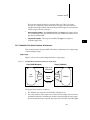
Validation Test Suite Software Architecture .................................. 141
Configuring the BSP VTS ................................................................................ 143
7.3.1
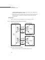
Hardware Setup ................................................................................. 143
7.3.2
Installing the BSP VTS ...................................................................... 145
x
Contents
7.3.3
System Configuration ........................................................................ 147
Configuring the Host System ...........................................................
Configuring the Target Hardware ...................................................
Configuring VxWorks .......................................................................
Configuring the BSP VTS ..................................................................
7.4
8
147
147
148
149
Running the BSP VTS ...................................................................................... 153
7.4.1
Starting the BSP VTS ......................................................................... 153
7.4.2
Monitoring a BSP Test ....................................................................... 155
Writing Portable C Code .......................................................................................... 159
Background ......................................................................................... 159
8.1
Portable C Code ................................................................................................ 160
8.1.1
Data Structures ................................................................................... 160
Specify Field Widths .......................................................................... 161
Avoid Bit Fields .................................................................................. 161
8.1.2
In-Line Assembly ............................................................................... 162
8.1.3
Static Data Alignment ....................................................................... 163
8.1.4
Runtime Alignment Checking ......................................................... 163
Checking the Alignment of a Data Item ......................................... 163
Verifying Pointer Alignment ............................................................ 163
Unaligned Accesses and Copying ................................................... 164
8.1.5
Other Issues ........................................................................................ 165
Follow Strict ANSI Compilation ......................................................
Remove Compiler Warnings ............................................................
Avoid Use of Casts .............................................................................
Avoid inline Keyword .......................................................................
Avoid alloca( ) Function ....................................................................
Take Care with void Pointer Arithmetic .........................................
Use volatile and const Attributes ....................................................
Misuse of the register Attribute .......................................................
Avoid vector Name ............................................................................
Statement Labels ................................................................................
Summary of Compiler Macros .........................................................
xi
165
165
165
165
166
166
167
167
167
168
168
VxWorks 5.5
BSP Developer’s Guide
8.2
9
Tool Implementation ....................................................................................... 171
8.2.1
New Tool Macros File ....................................................................... 171
8.2.2
New Tool Directories ......................................................................... 171
8.2.3
BSP Makefile Changes ...................................................................... 171
8.2.4
Macro Definitions for GNU and Diab ............................................ 172
Documentation Guidelines ...................................................................................... 173
9.1
Introduction ...................................................................................................... 173
9.2
Written Style ..................................................................................................... 173
Sentences .............................................................................................
Punctuation ........................................................................................
Word Usage ........................................................................................
Spelling ................................................................................................
Acronyms ............................................................................................
Board Names ......................................................................................
9.3
174
174
174
175
178
179
Format ................................................................................................................ 180
Layout ................................................................................................. 180
Special Elements ................................................................................ 180
Displays ............................................................................................... 182
9.4
Subsections ........................................................................................................ 183
Library and Subroutine Reference Pages ....................................... 183
Target Information Reference Page: target.nr ................................ 186
9.5
Generating Reference Pages ........................................................................... 189
9.5.1
Files ...................................................................................................... 189
Source Directory ................................................................................ 189
Documentation Directories .............................................................. 190
9.5.2
Tools ..................................................................................................... 190
9.5.3
Text Formatting .................................................................................. 190
Markup Commands .......................................................................... 190
Tables ................................................................................................. 192
xii
Contents
9.5.4
10
Processing ........................................................................................... 193
Product Packaging ................................................................................................... 195
10.1
SETUP Developer’s Kit ................................................................................... 195
10.2
BSP Packaging .................................................................................................. 195
BSP Contents .......................................................................................
Default Configuration .......................................................................
Included Files .....................................................................................
Excluded Files .....................................................................................
Source of the Files ..............................................................................
Vendor-Supplied Shared Files ..........................................................
10.2.1
A
BSP Media ........................................................................................... 200
10.3
Component Packaging .................................................................................... 200
10.4
Project Packaging ............................................................................................. 201
Upgrading a BSP for Tornado 2.0 ........................................................................... 203
A.1
Porting Issues .................................................................................................... 203
A.2
Code Interface Changes ................................................................................... 204
A.3
Project Issues ..................................................................................................... 205
A.4
Product Contents .............................................................................................. 205
A.5
B
196
196
197
197
198
199
A.4.1
Product Restrictions ........................................................................... 206
A.4.2
Product Requirements ....................................................................... 207
Summary ........................................................................................................... 208
Upgrading a BSP for Tornado 2.2 ........................................................................... 211
B.1
Architecture-Independent Changes to BSPs ................................................ 211
B.2
Architecture-Dependent BSP Issues .............................................................. 214
B.2.1
Migration Changes Common to All Architectures ....................... 214
xiii
VxWorks 5.5
BSP Developer’s Guide
B.2.2
68K/CPU32 ........................................................................................ 215
B.2.3
ARM .................................................................................................... 215
B.2.4
ColdFire ............................................................................................... 216
B.2.5
MIPS .................................................................................................... 216
B.2.6
Pentium ............................................................................................... 217
B.2.7
PowerPC ............................................................................................. 218
B.2.8
XScale/StrongARM ........................................................................... 219
B.2.9
SuperH ................................................................................................ 220
C
Upgrading a BSP for the VxWorks Network Stack ................................................ 221
D
VxWorks Boot Sequence ......................................................................................... 223
E
Component Language .............................................................................................. 231
E.1
Component Description Language (CDL) ................................................... 231
E.1.1
Component Properties ...................................................................... 232
E.1.2
Parameter Properties ......................................................................... 234
E.1.3
Folder Properties ............................................................................... 235
E.1.4
Selection Properties ........................................................................... 235
E.1.5
InitGroup Properties ......................................................................... 236
E.2
Folder Hierarchy .............................................................................................. 236
E.3
Project Initialization Order ............................................................................. 238
E.3.1
romInit.s .............................................................................................. 239
E.3.2
romStart.c ............................................................................................ 239
E.3.3
usrEntry.c ............................................................................................ 239
E.3.4
sysALib.s ............................................................................................. 240
E.3.5
prjConfig.c .......................................................................................... 240
xiv
Contents
F
G
Generic Drivers ......................................................................................................... 247
F.1
Introduction ...................................................................................................... 247
F.2
Serial Drivers ..................................................................................................... 248
F.3
Multi-Mode Serial (SIO) Drivers .................................................................... 249
F.4
Timer .................................................................................................................. 251
F.5
Non-Volatile Memory ...................................................................................... 252
F.6
VMEbus ............................................................................................................. 253
F.7
DMA ................................................................................................................... 254
F.8
Interrupt Controllers ........................................................................................ 254
F.9
Multi-Function .................................................................................................. 254
F.10
PCI Bus ............................................................................................................... 255
Upgrading 4.3 BSD Network Drivers ...................................................................... 257
G.1
G.2
G.3
Introduction ...................................................................................................... 257
G.1.1
Structure of a 4.3 BSD Network Driver .......................................... 258
G.1.2
Etherhook Routines Provide Access to Raw Packets .................... 259
Upgrading to 4.4 BSD ...................................................................................... 260
G.2.1
Removing the xxOutput( ) Routine ................................................. 261
G.2.2
Changing the Transmit Startup Routine ......................................... 262
G.2.3
Changes in Receiving Packets .......................................................... 262
G.2.4
Creating a Transmit Startup Routine .............................................. 263
Porting a Network Interface Driver to the END Model ............................. 264
Rewrite xxattach( ) to Use an endLoad( ) Interface ....................... 265
xxReceive( ) Still Handles Task-Level Packet Reception .............. 265
Rewrite xxOutput( ) to Use an endSend( ) Interface ..................... 265
xv
VxWorks 5.5
BSP Developer’s Guide
xxIoctl( ) is the Basis of endIoctl( ) .................................................. 266
H
Implementing a MUX-Based Network Interface Driver .......................................... 267
H.1
Introduction ...................................................................................................... 267
H.2
How VxWorks Launches and Uses Your Driver ......................................... 270
H.3
H.2.1
Launching Your Driver ..................................................................... 271
H.2.2
Your ISR Puts Work on the Network Job Queue ........................... 272
H.2.3
Executing Calls Waiting in the Network Job Queue .................... 273
H.2.4
Adding Your Network Interface Driver to VxWorks ................... 273
Guidelines for Handling Packet Reception in Your Driver ....................... 275
H.3.1
Setting Up and Using a Memory Pool for Receive and
Transmit Buffers
276
H.3.2
Swapping Buffers Between Protocol and Driver .......................... 280
H.3.3
Using Private Memory Management Routines ............................. 280
H.3.4
Supporting Scatter-Gather in Your Driver ..................................... 280
H.4
Indicating Error Conditions ........................................................................... 280
H.5
Required Driver Entry Points and Structures .............................................. 282
H.5.1
Required Structures for a Driver ..................................................... 283
Tracking Your Device’s Control Structure: DEV_OBJ ..................
Identifying the Entry Points into Your Network
Driver: NET_FUNCS ..........................................................
Tracking Link-Level Information: LL_HDR_INFO ......................
Tracking Data That Passes Between the Driver and the
Protocol: mBlk ......................................................................
H.5.2
286
287
288
Required Driver Entry Points .......................................................... 289
Loading the Device: endLoad( ) ......................................................
Unloading the Device: endUnload( ) ..............................................
Providing an Opaque Control Interface to Your
Driver: endIoctl( ) ................................................................
Sending Data Out on the Device: endSend( ) ................................
Starting a Stopped but Loaded Driver: endStart( ) .......................
xvi
285
290
291
292
293
294
Contents
Stopping the Driver Without Unloading It: endStop( ) ................
Handling a Polling Send: endPollSend( ) .......................................
Handling a Polling Receive: endPollReceive( ) .............................
Adding a Multicast Address: endMCastAddrAdd( ) ...................
Deleting a Multicast Address: endMCastAddrDel( ) ...................
Getting the Multicast Address Table: endMCastAddrGet( ) .......
Forming an Address into a Packet for Transmission:
endAddressForm( ) .............................................................
Getting a Data-Only mBlk: endPacketDataGet( ) .........................
Return Addressing Information: endPacketAddrGet( ) ...............
H.6
H.6.1
H.6.2
302
303
303
304
304
305
Protocol to MUX API ......................................................................... 305
The Protocol Data Structure NET_PROTOCOL ............................
Passing a Packet Up to the Protocol: stackRcvRtn( ) ....................
Passing Error Messages Up to the Protocol: stackError( ) ...........
Shutting Down a Protocol: stackShutdownRtn( ) .........................
Restarting Protocols: stackTxRestartRtn( ) .....................................
I
299
299
300
Writing Protocols That Use the MUX API .................................................... 301
Protocol Startup ..................................................................................
Sending Data ......................................................................................
Receiving Data ....................................................................................
Supporting Scatter/Gather Devices ................................................
Protocol Transmission Restart ..........................................................
Protocol Shutdown ............................................................................
H.7
294
295
296
296
297
298
306
307
308
309
310
Network Layer to Data Link Layer Address Resolution ............. 310
Converting an END Driver from RFC 1213 to RFC 2233 ........................... 311
Writing a SCSI-2 Device Driver ............................................................................... 317
I.1
Introduction ...................................................................................................... 317
I.2
Overview of SCSI ............................................................................................. 318
I.3
The SCSI Libraries ............................................................................................ 321
I.3.1
SCSI Manager (scsiMgrLib) .............................................................. 322
I.3.2
SCSI Controller Library (scsiCtrlLib) .............................................. 324
I.3.3
SCSI Direct Access Library (scsiDirectLib) .................................... 324
xvii
VxWorks 5.5
BSP Developer’s Guide
I.4
I.3.4
SCSI Sequential Access Library (scsiSeqLib) ................................. 324
I.3.5
SCSI Common Access Library (scsiCommonLib) ........................ 324
I.3.6
An Execution Example ..................................................................... 325
The SCSI Driver Programming Interface ...................................................... 325
I.4.1
Basic SCSI Controller Driver ............................................................ 325
I.4.2
Advanced SCSI Controller Driver ................................................... 334
I.5
The BSP Interface ............................................................................................. 357
I.6
Guidelines for Developing a SCSI Driver .................................................... 359
I.7
Test Suites .......................................................................................................... 360
scsciDiskThruputTest( ) ....................................................................
scsiDiskTest( ) .....................................................................................
scsiSpeedTest( ) ..................................................................................
tapeFsTest( ) ........................................................................................
I.8
360
361
362
363
Troubleshooting and Debugging ................................................................... 364
J
BSP Validation Test Suite Reference Entries ......................................................... 365
K
BSP Validation Checklists ....................................................................................... 401
L
Refgen ....................................................................................................................... 415
M
BSP Product Contents ............................................................................................. 423
Index .......................................................................................................................... 427
xviii
1
Overview
1.1 Introduction
One strength of VxWorks is that it provides a high degree of architectural and
hardware independence for application code. This portability is due to VxWorks’s
modular design, which isolates all hardware-specific functionality into a set of
libraries called the Board Support Package (BSP). The BSP libraries provide an
identical software interface to the hardware functions of all boards. They include
facilities for hardware initialization, interrupt handling and generation, hardware
clock and timer management, mapping of local and bus memory spaces, memory
sizing, and so on.
Broadly speaking, there are several types of VxWorks porting activity:
■
Host Porting: Porting Tornado and VxWorks development capability to a
previously unsupported host.
■
Architecture Porting: Porting VxWorks and the Tornado debugger to a
previously unsupported target processor type or architecture.
■
Board Porting: Porting VxWorks to a new target board, for which there is
already an architecture port and a host port available.
■
Upgrading pre-Tornado BSPs to work with Tornado.
■
Porting an optional Component to a Tornado release.
Host ports and architecture ports require access to the entire VxWorks source code
and are outside the scope of this manual. Board porting, the focus of this manual,
requires access to just the hardware-dependent source within VxWorks and the
debugger. This source code is the BSP.
1
VxWorks 5.5
BSP Developer’s Guide
Over the years, Wind River has been able to offer a wide range of BSPs to
customers. However, with the proliferation of many new CPU boards (many of
which are custom designs) Wind River alone has not been able to keep up with the
demand for new BSPs.
The Tornado BSP Developer’s Kit for VxWorks (BSP Kit) is intended to help you
create, document, and test new BSPs, components, and projects. The process of
porting VxWorks to a new board can be challenging, primarily because the
VxWorks development tools are unavailable until after the porting is finished.
Wind River has developed strategies that make porting easier. This BSP Kit
provides these strategies and a detailed look at how the system elements interact.
It also includes the technical information that a third party needs in order to create
and distribute components and projects based upon Tornado 2.x.
This release of the BSP Kit is compatible with Tornado 2.0 or later. Upgrading
earlier BSPs to work with the Tornado 2.x product is a relatively simple task. For
more information, see A. Upgrading a BSP for Tornado 2.0 or B. Upgrading a BSP for
Tornado 2.2.
New Features for Tornado 2.x
■
SCSI 1 Dropped Support for SCSI-1 drivers and libraries has been dropped. These
libraries are still included in Tornado 2.0, but they are classified as obsolete and
will not be included in future releases.
■
Macro TYCO5_2 Deleted The TYCO5_2 macro is no longer supported. Customers
should be using SIO drivers for Tornado 2.x.
■
BSP Packaging Changes Refer to 10.2 BSP Packaging, p.195 for details on
packaging requirements. See M. BSP Product Contents for a quick summary of a
typical product contents.
■
Documentation All on-line documentation is now provided as HTML pages. A
utility called refgen that generates HTML from existing nroff input is included in
the system.
■
VxWorks Network Stack The network stack, which was an option for Tornado 1.0.1
users, is now the only stack supported. It is referred to as the VxWorks network
stack. All BSPs have been converted to use drivers modified for the VxWorks
network stack (BSD 44 stack). In BSPs where both BSD44 and END drivers are
available, the END driver has been selected as the default driver for the BSP.
2
1
Overview
■
New Drivers Many new END network drivers have been added to the driver
product in order to provide as many BSPs as possible with at least one available
END driver.
■
Integrated Simulators Tornado 2.x includes an integrated simulator with the base
product. This allows developers to begin application development before the
hardware environment is ready.
■
Integrated WindView The Tornado 2.x product contains an integrated WindView
tool for examining run-time behavior. Refer to the WindView User’s Guide for
information on how to use all the features of WindView.
■
VTS Test Updates The Validation Test Suite has received only minor updates that
allow it to work correctly with the new virtual I/O features of the target shell.
■
SCSI Test Suites The SCSI performance test suites, which were omitted from the
previous release of the porting kit, are now included on the CD-ROM.
■
ROM_WARM_ADRS This new macro has been introduced into the template BSPs
and some existing BSPs. It represents the warm entry point into the boot ROM
code, and is needed to remove the artificial computation of the entry point based
on CPU family. Normally, ROM_WARM_ADRS is based on an offset from
ROM_TEXT_ADRS, for example:
#define ROM_WARM_ADRS
■
(ROM_TEXT_ADRS + 8)
New SIO IOCTLs New SIO IOCTL codes have been created to support modem
control lines. The IOCTLs SIO_OPEN and SIO_HUP notify the driver when the
device is opened and closed. The new IOCTLs SIO_HW_OPTS_SET and
SIO_HW_OPTS_GET allow the user to manage character length, parity, stop bits,
and modem control lines. The options bit CLOCAL disables modem control lines
from being used in the driver. For backward compatibility, the CLOCAL option is
selected by default in Wind River-supplied BSPs.
■
Target.txt File Removed. The text version of the target.nr file (generated for
Windows host users) has been eliminated. Both UNIX and Windows hosts now use
a browser for reading documentation in HTML format. The host utility refgen
takes nroff input and generates HTML output.
3
1
VxWorks 5.5
BSP Developer’s Guide
Prerequisites
Users of the BSP Kit should have a working knowledge of low-level C
programming and assembly languages, familiarity with device drivers, familiarity
with interrupts, and general experience interfacing software with hardware. In
addition, you should be familiar with the Tornado development tools (at least to
the point of having read through the Tornado User’s Guide). Finally, you should
have a reference BSP that is a released Tornado BSP based on the same CPU used
by your target.
You should also have the template BSP for your architecture and the template
drivers. Most customers also purchase one or more of the driver source code
products as well.
BSP Kit Components
The BSP Kit consists of a documentation set and a CD-ROM with software. The
documentation set consists of an installation guide and this manual, which is
summarized in Documentation, p.5. The software consists of the following:
■
BSP Validation Test Suite (VTS). The purpose of these programs is to exercise
the basic functionality of a BSP, and, in the process, note and report any
defects. These programs run on both the target machine and the supported
hosts. Feel free to enhance existing tests or create new ones. However, the basic
set of tests provided by the VTS is the standard by which BSPs are judged.
The test suite is highly automated. Once started, a BSP test requires no user
intervention, ensuring repeatability of the tests and also reducing the tedium
of running the tests by hand.
The VTS is distributed in source form to facilitate maintenance and extension.
When performing official validation testing, the tests should not be modified
from their original code.
■
Template BSPs. These templates are provided for all architecture types. These
templates provide a starting point for BSP development. Each template
compiles, but nearly every optional feature has been disabled. This allows
quick-starting from a copy of the template directory, without having to make
major changes.
■
Template Drivers. Template drivers are provided for all device types.
■
SCSI Test suite. A suite of SCSI test programs is included. Please refer to the
test programs in the target/src/test/scsi directory.
4
1
Overview
Included with Tornado (not the BSP Kit) is a reference BSP appropriate to the
architecture you specified when you ordered Tornado. This is a full working BSP.
Use this reference BSP as the source for many of the header files and object
modules in the BSP you create.
For instructions on how to install the BSP Kit, the reference BSP, or any other Wind
River software product, see the Tornado Getting Started Guide.
Documentation
The BSP Kit documentation includes the Tornado Getting Started Guide and this
manual.
This Manual
This user’s guide contains information on all aspects of writing, documenting, and
testing a BSP. This manual also details the standards that should be used for both
C source code and documentation, and provides information on how to write
network interface drivers, SCSI device drivers, and other drivers. The chapters of
this manual are summarized below:
■
1. Overview (this chapter)
■
2. BSP Organization is an overview of BSP construction and requirements. It
discusses required and optional files and routines. This is the basic overview
of what constitutes a BSP and how it interacts with VxWorks.
■
3. Creating a New BSP presents strategies for beginning a BSP port. Several
methods for getting started using different hardware configurations are
discussed. Getting started without having a working VxWorks boot ROM is
the most difficult part of porting to a new board.
■
4. Hardware Guidelines discusses CPU architectural considerations and how
different hardware elements can influence the BSP porting effort.
■
5. Driver Guidelines provides guidelines for device drivers in general. Specific
details of drivers are found elsewhere in various appendices describing
particular device types.
■
6. Components describes how a BSP interacts with components. This chapter
provides the basis for component creation and usage.
5
1
VxWorks 5.5
BSP Developer’s Guide
■
7. Validation Testing describes the operation and use of the BSP Validation Test
Suite (VTS), a collection of programs that run on the host and target machines
to exercise the basic functionality of BSPs and to detect and report defects
found in them. Documentation for the test suite programs and the individual
tests can be found in J. BSP Validation Test Suite Reference Entries. A checklist to
be followed for BSP testing is found in K. BSP Validation Checklists.
■
8. Writing Portable C Code describes how to write compiler-independent
portable C code. The goal is to write code that does not require changes in
order to work correctly with different compilers.
■
9. Documentation Guidelines covers Wind River conventions for style and
format, and the procedures for generating BSP documentation from source
modules. The template BSPs supplied with the BSP Kit provide examples of
the writing style, text format, module layout, and text commands discussed
throughout this section.
■
10. Product Packaging discusses the content and format of the BSP product that
is delivered to the end user.
■
A. Upgrading a BSP for Tornado 2.0 describes how to convert an existing
Tornado 1.0.1./SENS BSP to a Tornado 2.0 BSP.
■
B. Upgrading a BSP for Tornado 2.2 discusses the migration of a BSP from
Tornado 2.0 to 2.2. It includes information on both architecture-independent
and architecture-dependent issues.
■
C. Upgrading a BSP for the VxWorks Network Stack describes the BSP update
procedure for the network stack. This is only for BSPs that were not previously
updated for the Tornado 1.0.1 SENS stack product.
■
D. VxWorks Boot Sequence provides a detailed look at the full VxWorks boot
sequence. It identifies each step by its function, its name, and its source
location.
■
E. Component Language provides a technical summary of the Component
Description Language (CDL) used in component description files (CDFs). It
also presents a hierarchical view of the default component folders and their
initialization groups and sequencing.
■
F. Generic Drivers provides details on how to write other drivers used in the
VxWorks system.
■
G. Upgrading 4.3 BSD Network Drivers is an application note on converting a 4.3
BSD style driver to the 4.4 BSD interface required by the new network stack.
6
1
Overview
■
H. Implementing a MUX-Based Network Interface Driver describes the
requirements for a new Enhanced Network Driver (an END) that uses the
MUX to access all the features of the new network stack. Enhanced drivers
include polling and multicast support not available in the basic NETIF drivers.
■
I. Writing a SCSI-2 Device Driver describes how a VxWorks SCSI-2 device
driver fits into the VxWorks I/O system hierarchy, and how to write a SCSI-2
driver that interfaces with the VxWorks SCSI-2 library (scsi2Lib), which
provides the high-level SCSI-2 interface routines that are device independent.
■
J. BSP Validation Test Suite Reference Entries provides the detailed
documentation for using the BSP Validation Test Suite (BSP-VTS).
■
K. BSP Validation Checklists provides copies of the BSP validation checklists
used at Wind River. PostScript copies of the forms are included on the
CD-ROM.
■
L. Refgen documents use of the refgen tool for generating HTML reference
pages from traditional BSP source code.
■
M. BSP Product Contents lists the typical contents of a BSP product.
Other Documentation
The following documents provide important background information on
VxWorks and Tornado.
■
■
■
■
■
■
■
Tornado Getting Started Guide, 2.2
Tornado Release Notes, 2.2
Tornado User’s Guide, 2.2
VxWorks Programmer’s Guide, 5.5
VxWorks API Reference: Drivers, 5.5
VxWorks API Reference: OS Libraries, 5.5
Wind River Technical Notes (available from the WindSurf Web site)
Documentation Conventions
The remainder of this chapter describes this document’s conventions for cross
references, path names, and type.
Cross-References
Cross-references in this guide to a reference entry for a tool or module refer to an
entry in the VxWorks API Reference (for target libraries or subroutines) or to the
reference appendix in the Tornado User’s Guide (for host tools) or the BSP-specific
7
1
VxWorks 5.5
BSP Developer’s Guide
entries in the Tornado man directories. These references are also provided in the
Tornado Online Manuals. For more information about how to access online
documentation, see the Tornado User’s Guide: Documentation Guide.
Other references from one book to another are always at the chapter level, and take
the form Book Title: Chapter Name.
Path Names
The top-level Tornado directory structure includes three major directories (see the
Tornado User’s Guide: Directories and Files). Because all VxWorks files reside in the
target directory, this manual uses relative path names starting below that directory.
For example, if you install Tornado in /usr/wind, the full path name for the file
shown as config/all/configAll.h is /usr/wind/target/config/all/configAll.h.
NOTE: In this manual, forward slashes are used as path name delimiters for both
UNIX and Windows filenames.
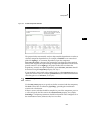
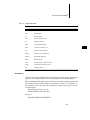
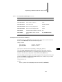
Typographical Conventions
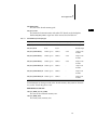
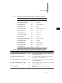
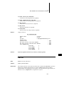
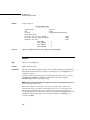
This manual uses the conventions shown in Table 1-1 to differentiate various
elements. Parentheses are always included to indicate a subroutine name, as in
printf( ).
Table 1-1
Font Usage for Special Terms
Term
Example
files, path names
/etc/hosts
libraries, drivers
memLib, nfsDrv
host tools
more, chkdsk
subroutines
semTake( )
boot commands
p
code display
main ();
keyboard input
make CPU=MC68040 ...
display output
value = 0
user-supplied parameters
name
constants
INCLUDE_NFS
8
1
Overview
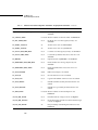
Table 1-1
Font Usage for Special Terms (Continued)
Term
Example
C keywords, cpp directives
#define
named key on keyboard
RETURN
control characters
CTRL+C
lower-case acronyms
fd
1
9
VxWorks 5.5
BSP Developer’s Guide
10
2
BSP Organization
2.1 Introduction
This chapter describes the components of a BSP. It lists and describes the contents
of all the BSP-associated source and include files. For the .h files, this chapter
describes the consequences of defining or undefining the standard symbolic
constants. For the .c files, it describes all the required and optional functions
associated with the file. This chapter describes the derived files, such as sysLib.o
(the interface between board-dependent and board-independent code) and
bootrom.
There is a section enumerating the principal BSP-associated routines and their
order of invocation (for a tabular summary of the boot sequence, see D. VxWorks
Boot Sequence). This information is provided to give you the system awareness
needed to debug the VxWorks boot phase.
At the end of this chapter is a discussion of mistakes commonly made by the
novice BSP developer.
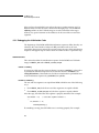
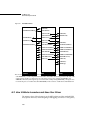
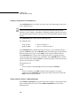
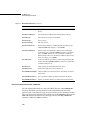
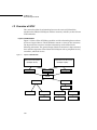
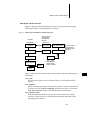
2.2 BSP Components
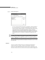
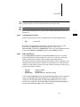
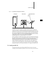
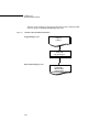
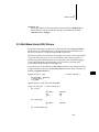
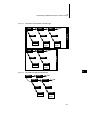
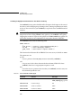
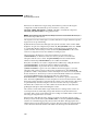
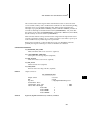
A BSP consists of the routines that provide VxWorks with its main interface to the
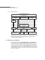
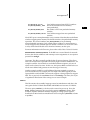
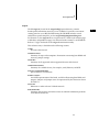
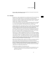
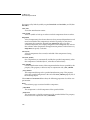
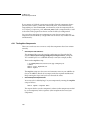
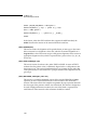
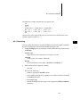
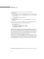
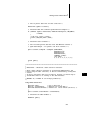
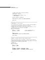
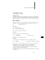
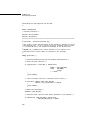
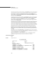
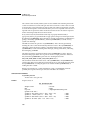
hardware environment. Figure 2-1 illustrates the various components of VxWorks,
indicating the hardware-dependent and -independent elements.
11
VxWorks 5.5
BSP Developer’s Guide
Figure 2-1
VxWorks Components
Hardware-Independent Software
Tools - Applications
I/O System
VxWorks Libraries
TCP/IP
File
System
Hardware-Dependent Software
wind Kernel
SCSI
Driver
Network
Driver
BSP
Hardware
SCSI
Controller
Serial
Controller
Clock
Timer
Ethernet
Controller
The BSP routines are contained in a number of C and assembly files that you must
create (or modify, if starting with a template BSP). The rest of this section
summarizes BSP files and directories.
2.2.1 BSP Source and Include Files
This section describes the directories target/config/all and target/config/bspname.
Strictly speaking, the files in target/config/all are not part of the BSP, but the
modules defined there are shared by all BSPs. Familiarity with these modules is
essential if you want to understand your particular BSP. When building project
images, the component configlettes in target/config/comps/src replace the files in
target/config/all. A configlette is any C source code compiled by the project facility
as a part of the project build step. Such files provide only some limited part of the
final project configuration.
12
2
BSP Organization
Files in the target/config/all Directory
The files in target/config/all are delivered as part of the VxWorks architecture
product. Do not alter these files unless absolutely necessary. Of special concern is
configAll.h. This file sets the default configuration for all VxWorks images. The
values you define here should be generic and therefore true for most if not all
VxWorks developers at your site. If you need a VxWorks image that differs from
the default configuration, use your BSP’s config.h to override (#define or #undef)
the default values in configAll.h.
Files in config/all are not directly used when building a project. They are scanned
only once when a new project is made from a BSP. Any changes to the files in
target/config/all after a project has been created do not affect the project. If a
change is desired, the user must make the change directly in the project area.
!
CAUTION: Changing configAll.h from the command line can have unpleasant
side effects for other VxWorks users at your site. This note only applies to building
from the command line. One benefit of the Tornado project facility is that changes
do not affect existing projects. Only new projects created from a BSP after the
change to configAll.h inherit that change.
bootConfig.c – Main Initialization for Boot ROM Images
The bootConfig.c file is the main initialization and control file for all boot ROM
images. It includes the complete boot ROM shell task. It contains a table (NETIF)
for network device initialization. This module is a subset of usrConfig.c. Boot
ROM images do not provide all of the optional features available in the full
VxWorks images. Of particular note is that boot images do not use MMU libraries
(except for SPARC).
The Tornado project facility does not have the ability to create and manipulate a
boot ROM project. For projects created from a BSP, there is a button that performs
the traditional command-line creation of a boot ROM image from the Build menu.
Please take note that project-specific configuration information has no effect at all
when the boot ROM image gets built. Only the traditional config.h, configAll.h,
bootConfig.c, and bootInit.c files affect the building of a boot ROM image.
bootInit.c – Second-Stage ROM Initialization
The bootInit.c file is the second stage of boot ROM initialization, after romInit.o.
The romInit( ) routine in romInit.s terminates by jumping to romStart( ), defined
in this file. The routine romStart( ) performs the necessary code uncompression
and relocation for ROM images. First it copies the text and data segments from
13
2
VxWorks 5.5
BSP Developer’s Guide
ROM to RAM. Then it clears those parts of main RAM not otherwise used. Finally
it uncompresses the compressed portion of the image. Different configuration
options can modify how these operations are performed.
In a project being built for Tornado 2.x, the configlette romStart.c replaces the
functionality of bootInit.c. (For a ROMed VxWorks image only. Not for a boot
ROM image).
dataSegPad.s – VxVMI Text Segment Protection
The dataSegPad.s file is used only for VxVMI text segment protection. It insures
that text and data segments do not share an MMU page.
usrConfig.c – Initialization Code for VxWorks Image
The userConfig.c file contains the main initialization code for traditional VxWorks
images. Unlike bootConfig.c, which is fully self-contained, usrConfig.c includes
target/src/config/usrExtra.c, which includes other files that provide subsystem
initialization and configuration.
This file is used only when building from the command line, as was done in
Tornado 1.0. When building projects using the project facility, project initialization
groups determine the order of component initialization. Each component has a set
of properties that specify which initialization group it belongs to and where in that
group it belongs.
Files in the target/config/comps/vxWorks Directory
Files under this directory are the basic component descriptor files (CDF files) for
the VxWorks real-time kernel. Refer to 6. Components for more information on how
components are created, used, and delivered. Refer to E.1 Component Description
Language (CDL), p.231 for details on the syntax for CDF files.
Files in the target/config/comps/src Directory
The files in this directory represent the configlettes associated with the kernel
components. They represent code fragments formerly found in
target/config/all/usrConfig.c and in target/src/config.
14
2
BSP Organization
Files in the target/config/bspname Directory
2
The target/config/bspname subdirectory contains the system or
hardware-dependent files for the BSP.
README
The README file contains the BSP release record. It records each release version
and revision and documents work done on the BSP as a whole. This file was first
introduced with Tornado 1.0.
Makefile and depend.bspname
The makefile controls the building of images from the command line. Beginning
with VxWorks 5.2, the standard make utility was GNU make, and the current
make technology continues to use many of the advanced features available in
GNU make. The BSP make system includes make subfiles located in the
target/h/make directory. If a dependencies file does not already exist, make
automatically generates a depend.bspname file that it uses to track all module
dependencies. The depend.bspname dependency file is not shipped with the BSP, it
is a generated file. For more information on customizing the makefile, see the
Tornado User’s Guide, 2.2.
Within the makefile, you must define the following macros:
CPU
The target CPU architecture (for example, MC68040).
TOOL
The host tool chain (for example, gnu).
TARGET_DIR
The target directory (BSP) name.
VENDOR
The target manufacturer’s name.
BOARD
The target name.
ROM_TEXT_ADRS
Specifies the boot ROM entry address in hexadecimal. For most boards, this is
set to the beginning of the ROM address area. However, if your hardware
configuration uses an area at the start of ROM for the reset vector, you should
offset accordingly.
15
VxWorks 5.5
BSP Developer’s Guide
ROM_WARM_ADRS
The warm entry point to the boot ROM code.
ROM_SIZE
The ROM area’s size in hexadecimal.
RAM_LOW_ADRS
The address at which to load VxWorks.
RAM_HIGH_ADRS
The destination address used when copying the boot ROM image to RAM.
config.h
The config.h file contains all includes and definitions specific to the CPU board.
The standard organization of config.h contents is roughly as follows:
(1) BSP version and revision ID numbers
(2) configAll.h (#included)
(3) memory caching and MMU configuration
(4) shared memory network definitions
(5) on-board memory addresses and size
(6) ROM addresses and size
(7) non-volatile memory (NVRAM) parameters
(8) the default bootline parameters
(9) timestamp driver support
(10) external bus address mapping
(11) network device and interrupt vectors
(12) bspname.h file (#included)
NOTE: A config.h file should include both configAll.h and bspname.h.
BSP Release Numbers. The release number for a BSP consists of its version
number and revision number. A BSP’s version number identifies a BSP’s
generation. A BSP’s revision number is an incrementing number that identifies a
particular release of a BSP within its generation.
16
2
BSP Organization
Version 1.0 BSPs are written for all standard VxWorks releases up to and including
VxWorks 5.2. Version 1.1 BSPs are written for Tornado 1.0 and Tornado 1.0.1.
Version 1.2 identifies a BSP designed for use with Tornado 2.x. The main interface
differences between 1.1 and 1.2 BSPs is support for the networking stack and
different packaging. With each new version sequence, the revision number begins
with 0 and is incremented each time the BSP is released for production.
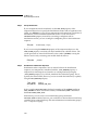
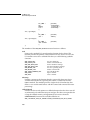
To specify a BSP version number, you can define BSP_VERSION to be the string
“1.2” or “1.1”. Otherwise, you can define either of the macros BSP_VER_1_1 or
BSP_VER_1_2, whichever is appropriate. To set the revision number, use BSP_REV,
which you should set to a string value such as “/0”. The revision number includes
the slash character. The full BSP release number is the concatenation of the two
string macros BSP_VER and BSP_REV: for example, “1.2/0”.
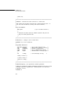
Thus, to set a BSP’s release number to “1.2/0”, define the following:
#define
#define
#define
#define
BSP_VER_1_1
BSP_VER_1_2
BSP_VERSION "1.2"
BSP_REV "/0" /* Increment for each new release */
configAll.h. Include configAll.h (located in the target/config/all directory) in your
config.h so the reasonable configuration defaults for a BSP are adopted. Use
config.h as the main user-editable configuration file for your BSP.
Use config.h as the main user-editable configuration file for your BSP. To pick up
the reasonable configuration defaults for a BSP at your site, your config.h should
include configAll.h (located in the target/config/all directory).1
Within your config.h you can override these site defaults, with values more
appropriate to this particular BSP. You should also present your config.h to
subsequent users of your BSP as the configuration file that they should edit either
to override configAll.h or to configure whatever optional features you have built
into your BSP.
When building project images, components and parameters selected using the
project override any values assigned in either configAll.h, config.h, or even
bspname.h. Any macro known to the project facility is assigned the project value,
overriding any other assignment.
1. Here, the term “user” refers to developers who use your BSP to build their VxWorks applications. In addition, if a value is not optional but always required and must not be edited,
set it in bspname.h, not config.h.
17
2
VxWorks 5.5
BSP Developer’s Guide
!
CAUTION: A config.h file should not include configAll.h until after
BSP_VERSION and BSP_REV have been defined. If they are not defined,
configAll.h, assigns default values.
If you include BSP-specific configuration options in config.h, try to make those
options as user-friendly as possible. Ideally, users should immediately understand
the use of an option from its name alone. In addition, do not expect users to
perform calculations to set a configuration option. For example, you should make
the code (or the compiler) figure out register values based on whether a
meaningfully named constant is defined.
Cache and MMU Configuration. The default cache and MMU configuration are
architecture dependent. They are usually configured to maximize board
performance. Depending on the architecture, cache and the MMU can be
completely independent or highly integrated. Usually, when the MMU is enabled,
it assumes control of caching on a page-by-page basis. This means that the macros
USER_I_CACHE_MODE and USER_D_CACHE_MODE do not usually affect caching
when the MMU is enabled. For detailed information on cache and MMU
interactions, refer to the relevant VxWorks Architecture Supplement document.
Most BSPs undefine the configAll.h default settings for cache and MMU, and
redefine them in config.h just to allow users to make their own selections more
easily. Doing so brings the settings to the direct attention of users when they make
configuration changes. Of course, if cache mode is not a user-changeable option,
these macros should be defined in bspname.h instead of config.h.
Shared Memory Network Definitions. This section describes the parameters needed
to configure the shared memory network driver (for additional information, refer
to the VxWorks Network Programmer’s Guide: Data Link Layer Network Components).
The shared memory network allows a number of CPU boards in a system to
communicate via shared memory. The following constants are important when the
shared memory network is initialized:
SM_ANCHOR_ADRS
The backplane anchor address. The anchor contains a pointer to the actual
shared memory pool. If the on-board memory is being dual-ported, then the
allocated memory’s low address + 0x600 is the default used by Wind River. If
a memory board is used, then the base address of this memory is used.
SM_MEM_ADRS
The location of the shared memory. Specifying NONE means that the memory
is to be dynamically located from the master’s on-board dual-ported memory
using malloc( ).
18
2
BSP Organization
SM_MEM_SIZE
The size of the shared memory pool.
2
SM_INT_TYPE
The method of communication with other CPU boards on the backplane.
Define SM_INT_TYPE to equal one of the macros listed in Table 2-1.
Table 2-1
Shared Memory Interrupt Types
SM_INT_TYPE
SM_INT_ARG1
SM_INT_ARG2
SM_INT_ARG3
Meaning
SM_INT_NONE
-
-
-
Polling
SM_INT_BUS
level
vector
-
Bus interrupt
SM_INT_MAILBOX_1
address space
address
value
1-byte write
mailbox
SM_INT_MAILBOX_2
address space
address
value
2-byte write
mailbox
SM_INT_MAILBOX_4
address space
address
value
4-byte write
mailbox
SM_INT_MAILBOX_R1 address space
address
-
1-byte read
mailbox
SM_INT_MAILBOX_R2 address space
address
-
2-byte read
mailbox
SM_INT_MAILBOX_R4 address space
address
-
4-byte read
mailbox
For information on changes made to the shared memory subsystem for Tornado
2.2, see the Tornado Migration Guide.
RAM Addresses and Size.
LOCAL_MEM_LOCAL_ADRS
The start of the on-board memory area.
LOCAL_MEM_SIZE
The fixed (static) memory size.
19
VxWorks 5.5
BSP Developer’s Guide
LOCAL_MEM_AUTOSIZE
Run-time (dynamic) memory sizing. For more information, see Wind River
Technical Note #42.
USER_RESERVED_MEM
Reserved memory size (bytes). For more information, see Wind River Technical
Note #41.
RAM_HIGH_ADRS
The destination address used for copying the boot ROM image. It is usually
the on-board memory start address plus 0x00100000. This must be the same
value as defined in the makefile (see Makefile and depend.bspname, p.15).
ROM Addresses and Size.
ROM_BASE_ADRS
The ROM start address in hexadecimal.
ROM_TEXT_ADRS
The boot ROM entry address in hexadecimal. For most boards, this is set to the
beginning of the ROM address area. However, there are boards that use some
area at the start of the ROM address area for the reset vector. This must be the
same value as defined in the makefile (see Makefile and depend.bspname, p.15).
ROM_LINK_ADRS
If used, this macro specifies the boot ROM link address in hexidecimal form.
For most boards, this is set to the beginning of the ROM address area. If this
address is present, the linker uses it to link the boot ROM image. Otherwise,
ROM_TEXT_ADRS is used as the link address.
ROM_WARM_ADRS
The warm boot entry address. This is usually defined as an offset from
ROM_TEXT_ADRS.
ROM_SIZE
The size of the ROM area in hexadecimal. This must be the same value as
defined in the makefile (see Makefile and depend.bspname, p.15).
Non-Volatile Memory. The routines sysNvRamSet( ) and sysNvRamGet( ) have an
offset parameter. If NV_BOOT_OFFSET is greater than zero, you can access the bytes
before the boot line by specifying a negative offset. To override the default value of
NV_BOOT_OFFSET, first undefine the macro in config.h, then define it.
20
2
BSP Organization
For boards without NVRAM, include the file mem/nullNvRam.c so that calls to
NVRAM routines return ERROR. This file is provided on the BSP Kit CD-ROM in
the target/src/drv/mem directory.
There is a generic NVRAM driver called templateNvRam.c. See comments in this
file for a description of the requirements and macros needed to use this driver. The
templateNvRam.c file is appropriate for all boards where NVRAM is byte
accessible, as opposed to block accessible.
NV_RAM_SIZE
The total bytes of NVRAM available. Define NV_RAM_SIZE in config.h. For
boards without NVRAM, define NV_RAM_SIZE as NONE.
BOOT_LINE_SIZE
The number of bytes of NVRAM that are reserved for the VxWorks boot line.
The default value is 255 and is defined in configAll.h. BOOT_LINE_SIZE must
be less than or equal to NV_RAM_SIZE. To override the default value of
BOOT_LINE_SIZE, first undefine the macro in config.h, then define it.
NV_BOOT_OFFSET
The byte offset to the beginning of the VxWorks boot line in NVRAM. The
default value is 0 and is defined in configAll.h.
Default Bootline Parameters. The DEFAULT_BOOT_LINE macro provides an
example bootline, which end users can alter to reflect their target environment.
This is particularly useful for targets without NVRAM, because it means the end
user does not have to re-enter the boot parameters on each power cycle.
Timestamp Support. Each BSP should have timestamp support for the WindView
product. The user configures timestamp support by defining or undefining the
macro INCLUDE_TIMESTAMP. See the comments in the timer driver source file for
a description of the additional support required by that specific driver.
External Bus Address Mapping. VMEbus mapping is controlled by a series of nine
macros for master window mapping and another set of nine standard macros for
slave window mapping. The user configures VME by defining INCLUDE_VME in
config.h. The VME mappings for A16, A24, and A32 space master access are
controlled by a sequence of three macros each.
It is assumed that the BSP honors all of these macros. If the hardware is fixed and
one or more sets of these macros must have fixed values, then those macros should
be moved from config.h to bspname.h. Only macros that the user can reasonably
change should be in config.h.
21
2
VxWorks 5.5
BSP Developer’s Guide
Use the following macros to define the windows onto the VMEbus from the local
CPU (bus master accesses):
VME_A16_MSTR_SIZE
VME_A16_MSTR_BUS
VME_A16_MSTR_LOCAL
VME_A24_MSTR_SIZE
VME_A24_MSTR_BUS
VME_A24_MSTR_LOCAL
VME_A32_MSTR_SIZE
VME_A32_MSTR_BUS
VME_A32_MSTR_LOCAL
Size of the window into A16 space.
First bus address of A16 window.
Local address of A16 window.
Size of the window into A24 space.
First bus address in A24 window.
Local address of A24 window.
Size of the window into A32space.
First bus address in A32 window.
Local address of A32 window.
Use the following macros to define the windows from the VMEbus into local
memory. By default, only CPU 0 exports its memory to an external bus. These
macros control bus slave windows that make local memory visible to the VMEbus.
Because of its small size, main memory is rarely mapped into an A16 slave
window. Setting the size of any window to 0 should disable that window.
VME_A16_SLV_SIZE
VME_A16_SLV_BUS
VME_A16_SLV_LOCAL
VME_A24_SLV_SIZE
VME_A24_SLV_BUS
VME_A24_SLV_LOCAL
VME_A32_SLV_SIZE
VME_A32_SLV_BUS
VME_A32_SLV_LOCAL
Size of the window onto A16 space.
Bus address of A16 window.
Local address mapped into A16 window.
Size of the window onto A24 space.
Bus address of A24 window.
Local address mapped into A24 window.
Size of the window onto A32space.
Bus address of A32 window.
Local address mapped into A32 window.
A standard set of macros to describe PCI address mapping has not yet been
formalized. Contact Wind River for the latest PCI interface standards. For
additional information, see Wind River Technical Note #44 and
target/src/drv/vme/templateVme.c.
PCI Address Macros. For PCI, you should describe at least 1 and sometimes 4
windows reaching from local bus space to PCI spaces. These are called the master
windows because the local CPU is the bus master for these transactions.
PCI_MSTR_MEM_SIZE
PCI_MSTR_MEM_BUS
PCI_MSTR_MEM_LOCAL
PCI_MSTR_IO_SIZE
PCI_MSTR_IO_BUS
22
Size of the window onto PCI memory space.
Bus address of PCI memory window.
Local address mapped into PCI memory
window.
Size of the window onto PCI I/O space.
Bus address of PCI I/O window.
2
BSP Organization
Local address mapped into PCI I/O window.
Size of the window onto PCI memory
(non-prefetched).
PCI_MSTR_MEMIO_BUS
Bus address of PCI non-prefetched memory
window.
PCI_MSTR_MEMIO_LOCAL Local address mapped into non-prefetched
window.
PCI_MSTR_IO_LOCAL
PCI_MSTR_MEMIO__SIZE
Not all PCI spaces are implemented in every situation. Note that there are different
windows mapping main memory. The default window is for prefetchable memory
operations. The second window, PCI_MSTR_MEMIO, is for performing
non-prefetchable operations. One or both of these windows to main memory is
always mapped. Our standard signal to disable a window is to set the size value
to zero, which should disable access from local memory to that space.
For more information on PCI macros, please refer to Wind River Technical Note #49.
Network Device and Interrupt Vector. If this BSP uses external boards for network
devices, then the bus addresses and interrupt vector assignments are user options
presented in config.h.
bspname.h. This file is normally included after all option selections. This allows
tests to be inserted into bspname.h to check for proper selection combinations. An
example would be a board that has two different Ethernet options, only one of
which can be selected at a time. In this case, the bspname.h file would check to see
if both were defined and generate an error message, if necessary.
Another example would be to add additional features required to support a
user-selected feature. For example, the user might select NFS support, and the
bspname.h file would add RPC and network support as being required to support
NFS. This is precisely what usrExtra.c does for usrConfig.c. Of course, this is just
a hypothetical illustration of the concept, not an actual example.
romInit.s
This file contains the assembly language source for initialization code that is the
entry point for the VxWorks boot ROMs and ROM-based versions of VxWorks.
The entry point, romInit( ), is the first code executed on power-up. It sets the
BOOT_COLD parameter to be passed to the generic romStart( ) routine. If the
hardware requires immediate memory mapping or setting special registers,
handle it here. Most hardware initialization occurs using the sysHwInit( ) routine
in sysLib.c.
23
2
VxWorks 5.5
BSP Developer’s Guide
There are three main functions that must be performed by romInit( ):
■
■
■
Disable interrupts and set up the CPU.
Set up the memory system. This usually involves turning off caches and
setting up memory controllers as needed. For the SPARC architecture, the
MMU must be enabled.
Set up the stack pointer and other registers to begin executing C code. The
address of the romStart( ) routine is calculated and the routine is called. There
is no return from romStart( ).
It is important to note that romInit( ) must be coded as position-independent code
(PIC). This is needed to support the complex boot strategies of VxWorks. If an
address cannot be made PC-relative, then it must be recomputed by subtracting
the symbol romInit and adding the value ROM_TEXT_ADRS. This is usually done
by a macro ROM_ADRS.
#define ROM_ADRS(x) ((x) - _romInit + ROM_TEXT_ADRS)
It is a common mistake for BSP writers to attempt too much initialization in
romInit.s. Most other initialization functions are quite easily deferred to the
sysHwInit( ) function. Additionally, code in romInit.s should not call out to other
modules or routines. This causes linking problems for the compressed boot ROM
image and negates any benefits of compression.
Calling out from romInit.s to C level routines is possible but discouraged. Certain
C code uses absolute addressing rather than PC relative code and is therefore not
PIC. If a C routine is needed, then it should not be part of sysLib.c. Such a routine
should be placed in a separate module and included into the system by adding the
module to the makefile variable BOOT_EXTRA.
Another common mistake made by BSP writers is to assume that devices
initialized by romInit.s do not need to be reinitialized by sysALib.s or sysLib.c. A
VxWorks image does not assume that it was booted by the VxWorks bootrom
program. It must reset and reinitialize all devices and features for itself. Failure to
do this makes proper operation of a VxWorks image dependent on code executed
by a bootrom image. Linking of bootrom and VxWorks images in this way is not
desirable.
sysALib.s
This file contains the assembler source of target-specific, system-dependent
routines. All BSP routines should be coded in C. However, if there are compelling
technical reasons for resorting to assembler, you can place the routines in
sysALib.s.
24
2
BSP Organization
The entry point of the VxWorks image, _sysInit, is located in sysALib.s. It is the
first code executed after booting (see sysALib.s: sysInit( ), p.34). It is usual here to
perform all the functions performed by romInit.s, except for system memory
setup. The memory system should be initialized at this stage of the startup
procedure.
Unlike romInit.s, code in sysALib.s does not need to be written as PIC or to use
the ROM_ADRS macro to remap absolute addresses. It can call out to other
modules and routines.
sysLib.c
This file contains the C source of target-specific, system-dependent sysLib
routines. These routines provide the board-level interface on which VxWorks and
application code can be built in a system-independent way. Note that sysLib.c can
include drivers from the src/drv directory and that these drivers can include some
of the routines listed below. For more information, see 5. Driver Guidelines and
F. Generic Drivers.
Driver setup and initialization is usually done in a subfile, which is included in
sysLib.c. Common subfiles are named: sysSerial.c, sysScsi.c, sysNet.c, and so on.
The purpose of using subfiles is keeping the setup and initialization of a particular
device constant across all architectures. The setup file for one board using a
particular device should be the same for any other board using that same device.
Not every feature of a particular board is necessarily supported by this BSP
abstraction. Some boards provide functions with jumpers or PALs instead of
software controllable/readable registers. Other hardware configurations might
not support some normally expected basic features.
When features are missing, it is usually safe to code an empty stub that returns
ERROR or NULL (whichever is appropriate), if any return value is required.
sysSerial.c
This optional file contains all the serial I/O setup and initialization for the SIO
device drivers. It is not separately compiled, but is included from sysLib.c. The
purpose of separating serial initialization from sysLib.o is to modularize the code
and allow reuse of code between BSPs.
sysScsi.c
This optional file contains the SCSI-2 setup and initialization for the BSP. Like
sysSerial.c, it is included in sysLib.c.
25
2
VxWorks 5.5
BSP Developer’s Guide
sysNet.c
Optional setup and initialization for network interface devices.
bspname.h
Use bspname.h to set all non-optional, board-specific information as defined in this
file, including definitions for the serial interface, timer, and I/O devices. The
directory target/h/drv is where much of the information is located. The header files
of the drivers needed to port VxWorks to your board should be included at the
beginning of bspname.h.
This file is intended for constant information that is not subject to user
configuration. If any macros or values defined in bspname.h can be changed to
customize the system, then define those macros or values in config.h instead.
It is helpful to use a sample header file, because most constant names, basic device
addresses, and so on are already defined and just require refinement. The
following should be defined in bspname.h:
■
■
■
■
interrupt vectors/levels
I/O device addresses
the meaning of the device register bits
system and auxiliary clock parameters (maximum and minimum rates)
Also, use a board description macro prefix (for example, Heurikon is defined as
HK_) to indicate values that are board-specific.
Interrupt Vectors and Levels. Define all interrupt vectors and levels dictated by
hardware and not user changeable in bspname.h.
I/O Device Addresses. Define all I/O addresses fixed by hardware or otherwise
not user-changeable in bspname.h.
Meaning of Device Register Bits. For on-board control registers, define a macro
value for each bit or group of bits in each registers. Typically, such macro
definitions are placed in bspname.h if there is no better location for them.
System and Auxiliary Clocks. When given a new clock rate, the timer drivers use
these macros to determine if the new rate is valid:
SYS_CLK_RATE_MIN
SYS_CLK_RATE_MAX
AUX_CLK_RATE_MIN
AUX_CLK_RATE_MAX
26
Sets the minimum system clock rate.
Sets the maximum system clock rate.
Sets the minimum auxiliary clock rate.
Sets the maximum auxiliary clock rate.
2
BSP Organization
target.nr
The file target.nr, located in the target/config/bspname directory, contains
board-specific information necessary to run VxWorks. To provide a convenient
starting point for a new BSP, the BSP Porting Kit CD-ROM includes several
architecture-specific templates, such as target/config/template68k/target.nr.
For Tornado 2.x, the target.nr file is not processed as a UNIX-style reference page
or Windows-compatible text page. It is delivered to the customer as an HTML file.
Refer to L. Refgen for details on the refgen documentation utility.
This reference entry is divided into the following sections:
NAME
The name of the board.
INTRODUCTION
Summary of scope and assumptions. Instructions concerning boot ROMs and
necessary jumper settings.
FEATURES
Summary of all supported and unsupported features of the board.
HARDWARE DETAILS
Summary of available devices, for example, serial, Ethernet, and SCSI.
SPECIAL CONSIDERATIONS
Special features or restrictions.
BOARD LAYOUT
An ASCII representation of the board, useful for illustrating boot ROMs and
jumpers. Jumpers and jumper states are represented by the characters shown
in Table 2-2.
SEE ALSO
References to other relevant VxWorks manuals.
BIBLIOGRAPHY
Summary of data sheets and other sources of technical information pertinent
to the board and devices.
27
2
VxWorks 5.5
BSP Developer’s Guide
Table 2-2
ASCII Representation of Board Layout
Jumper Type
State
Character
Vertical jumper
Installed
x
Vertical jumper
Open
: (colon)
Vertical jumper (three-pin)
Up
U
Vertical jumper (three-pin)
Down
D
Horizontal jumper
Installed
- (dash)
Horizontal jumper
Open
" (quote)
Horizontal jumper (three-pin)
Left
L
Horizontal jumper (three-pin)
Right
R
2.2.2 Derived Files
The following files are derived from the source files, the system header files, driver
source files, and modules in the VxWorks archive libraries. These files are only
delivered for demonstration purposes. The user recreates some or all of these files
when configuring a system.
When you are working with a Tornado 2.x project, these derived files are found in
the project directory. Their counterparts in the BSP directory are used only when
building from the traditional command-line method.
NOTE: As of this release, boot ROMs cannot be built from the Tornado project
facility. Enhancement of the project facility to configure and build boot ROM
images is planned.
bootInit.o, bootInit_res.o, and bootInit_uncmp.o
There are three boot strategies available: compressed ROMs, uncompressed
ROMs, and ROM-resident ROMs. All three strategies can be used for boot ROMs
or VxWorks ROMs. The name of the module indicates the strategy it is used with.
28
2
BSP Organization
bootrom
This file is an object module containing the binary VxWorks boot ROM.
bootrom.hex
This is an ASCII file containing the VxWorks boot ROM code, suitable for
downloading over a serial connection to a PROM programmer. The default
encoding uses Motorola S-Records.
bootrom.Z.s and bootrom.Z.o
This is the source and object output that is the compressed image of the bootrom.o
module.
ctdt.o
This module handles C++ constructor/destructor functionality.
dataSegPad.o
The module insuring that the text and data segments do not share a common
memory page. For the VxVMI option, this module forces alignment of the data
segment in a different MMU page from the text segment.
symTbl.c and sysALib.o
These are the source and object files for the built-in symbol table.
sysLib.o and sysALib.o
These modules always go together as a pair. They are the output of the sysALib.s
and sysLib.c modules.
romInit.o
This module is the startup code for any ROM image, boot or VxWorks. For
Tornado, it works in conjunction with the romStart.o module instead of bootInit.o.
vxWorks and vxWorks.sym
The vxWorks file is the complete, linked VxWorks binary to be run on the target.
The vxWorks.sym file is the symbol table for the VxWorks binary. Both files are
created with the supplied configuration files.
29
2
VxWorks 5.5
BSP Developer’s Guide
vxWorks.st
This file is the complete, linked, standalone VxWorks binary with the symbol table
linked in.
target/proj/bspname_gnu/* and target/proj/bspname_diab/*
These directories contain the BSP project files and default build outputs. There are
two ways to create a new project: the preferred method uses the project facility; the
alternative uses the command make prj_gnu or make prj_diab from the command
line.
doc/vxworks/bsp/bspname/*.*
This directory contains the HTML documentation files that are incorporated into
the user’s help system when the product is installed. This documentation is
generated from the command line with the command make man.
2.2.3 Required Routines
The following routines are expected to be found in the sysLib.o module. If any
routine is missing, then an unresolved global error is encountered during linking.
sysBspRev( ) - return the BSP version and revision number
sysClkConnect( ) - connect a routine to the system clock interrupt
sysClkDisable( ) - turn off system clock interrupts
sysClkEnable( ) - turn on system clock interrupts
sysClkInt( ) - handle system clock interrupts (internal)
sysClkRateGet( ) - get the system clock rate
sysClkRateSet( ) - set the system clock rate
sysHwInit( ) - initialize the system hardware
sysHwInit2( ) - initialize additional system hardware
sysMemTop( ) - get the address of the top of logical memory
sysModel( ) - return the model name of the CPU board
sysNvRamGet( ) - get the contents of non-volatile RAM
sysNvRamSet( ) - write to non-volatile RAM
30
2
BSP Organization
sysSerialHwInit( ) - initialize the BSP serial devices to a quiescent state
sysSerialHwInit2( ) - connect BSP serial device interrupts
2
sysSerialChanGet( ) - get the SIO_CHAN device associated with a serial
channel
sysToMonitor( ) - transfer control to the ROM monitor
2.2.4 Optional Routines
The following routines are usually present on all targets. Those marked as
“internal” are internal to the BSP and are not called by the application.
sysAbortInt( ) - handle the ABORT button interrupt
sysAuxClkConnect( ) - connect a routine to the auxiliary clock interrupt
sysAuxClkDisable( ) - turn off auxiliary clock interrupts
sysAuxClkEnable( ) - turn on auxiliary clock interrupts
sysAuxClkInt( ) - handle auxiliary clock interrupts
sysAuxClkRateGet( ) - get the auxiliary clock rate
sysAuxClkRateSet( ) - set the auxiliary clock rate
sysPhysMemTop( ) - get the address of the top of physical memory
The following routines are normally present only on targets that have a bus
interface:
sysProcNumGet( ) - get the processor number
sysProcNumSet( ) - set the processor number
sysBusIntAck( ) - acknowledge a bus interrupt
sysBusIntGen( ) - generate a bus interrupt
sysBusTas( ) - test and set a location across the bus
sysBusTasClear( ) - clear a location set by sysBusTas( )
sysBusToLocalAdrs( ) - convert a bus address to a local address
sysIntDisable( ) - disable a bus interrupt level
sysIntEnable( ) - enable a bus interrupt level
sysLocalToBusAdrs( ) - convert a local address to a bus address
31
VxWorks 5.5
BSP Developer’s Guide
sysMailboxConnect( ) - connect a routine to the mailbox interrupt
sysMailboxEnable( ) - enable the mailbox interrupt
sysMailboxInt( ) - handle the mailbox interrupt (internal)
sysNanoDelay( ) - set a calibrated delay (spin loop)
2.3 VxWorks Boot Sequence
This section describes a typical VxWorks boot scenario. Fundamentally, all
processors execute the same logical steps when initializing and loading VxWorks,
although some may require an extra step or two, and others may skip certain steps.
Minimally, initializing a processor consists of providing a portion of code and
possibly some tables located at a specific location in memory that the processor
always jumps to on reset or power-up. This code sets the processor in a specific
state, initializes memory and memory addressing, disables interrupts, and then
passes control to additional bootstrapping code.
This section covers the boot sequence step-by-step for various configurations and
architectures. In some cases, this description can only provide an approximate
guide to the processor boot sequence because there may be unique variations for
specialized chips, such as the M68302 embedded controller.
To see the boot sequence for an image built from the traditional command line,
refer to D. VxWorks Boot Sequence. To see the boot sequence for an image built using
the project tool, refer to E.3 Project Initialization Order, p.238.
2.3.1 Processor Variances
The VxWorks Motorola 680x0 heritage is evident in the VxWorks boot sequence;
fortunately, most processors accommodate this scenario.
The Intel i960 is unique in requiring an Initial Boot Record (IBR) that contains an
exhaustive processor configuration table defining memory regions, interrupt table
information, exception handling, and so on. In a way, this is the first code executed
on the processor and must be in a fixed location, such as the Stack Pointer and
Program Counter on many other processors.
32
2
BSP Organization
The Motorola M68040 must be put in a transparent memory-mapping mode.
The Motorola M683xx family is a special case. These processors run on busless
boards that communicate with the outside world via serial lines; for this reason,
the boot ROMs contain an embedded standalone VxWorks shell
(vxWorks.st_rom.hex). This type of configuration may become more prevalent in
future busless systems.
2.3.2 Sequence Overview
The processor is first “jumped” to the entry point in ROM, which sets the status
word and creates a dummy stack; then it jumps to a C routine. A parameter on the
dummy stack determines whether to clear memory (cold start), and then copies the
rest of ROM into RAM (if the remainder of the ROM is compressed, then it is
uncompressed during the copy). Next, the processor jumps to the entry point in
RAM.2
The RAM entry point in bootConfig.c disables the cache, clears the bss segment to
zero, initializes the vector table, performs board specific initialization, and then
starts the multitasking kernel with a user booting task as its only activity.
The VxWorks boot ROM image is a standalone application in its own right. The
developer uses it to boot a new VxWorks image over the network and link in
application code. The boot ROM’s kernel is discarded; there is no trap mechanism
or reuse of this code. The application is linked with a new image built on the host.
2.3.3 Files and Routines
This section contains a more detailed explanation of how booting takes place,
organized by file and routine name. For clarity, the sequence has been broken
down into a number of main steps or function calls. The key functions are listed as
headings and shown in invocation order.
romInit.s: romInit( )
At power-up (cold start) the processor begins execution at romInit( ), always the
first routine in romInit.s. For warm starts, the processor begins execution at
2. The reason for executing the text segment from RAM is partly for speed (although it is not
faster in all situations), and to allow a uniform model for uncompression, which may be
insufficient reason for an application to retain this model, especially at the cost of wasted
RAM. Either way, the data segment and bss (uninitialized data) must be in RAM.
33
2
VxWorks 5.5
BSP Developer’s Guide
romInit( ) plus a small offset (see sysToMonitor( ) in sysLib.c). The romInit( )
routine disables interrupts, puts the boot type (cold/warm) on the stack, clears
caches, and branches to romStart( ) in bootInit.c. The stack is placed to begin
before the text section and grows in the opposite direction. The routine romInit( )
must do as little device setup as possible to start executing C code. Hardware
initialization is the function of the sysHwInit( ) routine in sysLib.c.
bootInit.c: romStart( )
The text and data segments are copied from ROM to RAM in these ways:
■
If the text segment is not ROM-resident, the text and data segments are copied.
■
If the text segment is ROM-resident, only the data segment is copied.
■
Unused memory is cleared to initialize it.
■
If necessary, decompression is done.
Atypically, the i960 invokes sysInit(bootType), which eventually invokes
usrInit(bootType), as on all other architectures.
sysALib.s: sysInit( )
VxWorks calls sysInit( ) in normal rebooting to avoid code redundancy, the i960
calls the routine during ROM initialization as well. The sysInit( ) routine, which
must always be the first routine defined in sysALib.s, invalidates caches if
applicable, initializes the system interrupt tables with default stubs, initializes the
system fault tables with default stubs, and initializes all the processor registers to
known default values. It enables tracing, clears all pending interrupts and finally
invokes usrInit(bootType).
This routine must duplicate the hardware initialization done by romInit( ). If not,
then features set up in the boot ROM code could transfer to the VxWorks image.
This is very undesirable as the configuration and initialization actions of the boot
ROM would have influence over the run-time VxWorks images. It would likely
result in the user rebuilding boot ROMs for configuration changes. It might also
result in the user having to use paired sets of boot ROMs and VxWorks images.
usrConfig.c and bootConfig.c: usrInit( )
The usrInit( ) routine (in usrConfig.c) saves information about the boot type,
handles all the initialization that must be performed before the kernel is actually
started, and then starts the kernel execution. It is the first C code to run in VxWorks.
It is invoked in supervisor mode with all hardware interrupts locked out.
34
2
BSP Organization
Many VxWorks facilities cannot be invoked from this routine. Because there is no
task context as yet (no TCB and no task stack), facilities that require a task context
cannot be invoked. This includes any facility that can cause the caller to be
preempted, such as semaphores, or any facility that uses such facilities, such as
printf( ). Instead, the usrInit( ) routine does only what is necessary to create an
initial task, usrRoot( ). This task then completes the startup.
The initialization in usrInit( ) includes the following:
■
Cache Initialization. The code at the beginning of usrInit( ) initializes the
caches, sets the mode of the caches and puts the caches in a safe state. At the
end of usrInit( ), the instruction and data caches are enabled by default.
■
Zeroing Out the System bss Segment. The C and C++ languages specify that
all uninitialized variables must have initial values of 0. These uninitialized
variables are put together in a segment called the bss. This segment is not
actually loaded during the bootstrap, because it is known to be zeroed out.
Because usrInit( ) is the first C code to execute, it clears the section of memory
containing bss as its very first action. While the VxWorks boot ROMs clear all
memory, VxWorks does not assume that the boot ROMs are used.
■
Initializing Interrupt Vectors. The exception vectors must be set up before
enabling interrupts and starting the kernel. First, intVecBaseSet( ) is called to
establish the vector table base address.
!
CAUTION: For some architectures, there are exceptions to the rule that
intVecBaseSet( ) must be called before enabling interrupts and starting the kernel.
See the appropriate VxWorks Architecture Supplement document.
After intVecBaseSet( ) is called, the routine excVecInit( ) initializes all exception
vectors to default handlers that safely trap and report exceptions caused by
program errors or unexpected hardware interrupts.
Initializing System Hardware to a Quiescent State. System hardware is initialized
by calling the system-dependent routine sysHwInit( ). This mainly consists of
resetting and disabling hardware devices that can cause interrupts after interrupts
are enabled (when the kernel is started). This is important because VxWorks ISRs
(for I/O devices, system clocks, and so on) are not connected to their interrupt
vectors until the system initialization is completed in the usrRoot( ) task. However,
because the memory pool is not yet initialized, you must not try to connect an
interrupt handler to an interrupt during the sysHwInit( ) call.
35
2
VxWorks 5.5
BSP Developer’s Guide
lib/*.a: kernelInit( )
The kernelInit( ) routine initiates the multitasking environment and never returns.
It takes the following parameters:
–
The application to be spawned as the “root” task, typically usrRoot( ).
–
The stack size.
–
The start of usable memory; that is, the memory after the main text, data, and
bss of the VxWorks image. All memory after this area is added to the system
memory pool, which is managed by memPartLib. Allocation for dynamic
module loading, task control blocks, stacks, etc., all come out of this region.
–
The top of memory as indicated by sysMemTop( ). If a contiguous block of
memory is to be preserved from normal memory allocation, set the macro
USER_RESERVED_MEM in config.h to the amount of reserved memory
desired.
–
The interrupt stack size. The interrupt stack corresponds to the largest amount
of stack space that could be used by any interrupt-level routine that might be
called (plus a safe margin for the nesting of interrupts).
–
The interrupt lock-out level. For architectures that have a level concept, it is the
maximum level. For architectures that do not have a level concept, it is the
mask to disable interrupts. See the appropriate VxWorks Architecture
Supplement.
The kernelInit( ) routine calls intLockLevelSet( ), disables round-robin mode, and
creates an interrupt stack if supported by the architecture. It then creates a root
stack and TCB from the top of the memory pool, spawns the root task, usrRoot( ),
and terminates the usrInit( ) thread of execution. At this time, interrupts are
enabled; it is critical that all interrupt sources are disabled and pending interrupts
cleared.
usrConfig.c and bootConfig.c: usrRoot( )
For the generic VxWorks development environment, usrRoot( ) initializes the I/O
system, installs drivers, creates devices, and then sets up the network as
configured in configAll.h and config.h.
The usrRoot( ) routine calls memInit( ). Optionally, it calls memShowInit( ) and
usrMmuInit( ).
The routine sysClkConnect( ) is the first routine called in the BSP after the system
is multitasking. It immediately calls sysHwInit2( ). This is an opportune time for
36
2
BSP Organization
further board initialization that could not be completed in sysHwInit( ); for
example, an intConnect( ) of additional devices may be done in sysHwInit2( ).
The 60 Hz system clock is set up by calling sysClkRateSet( ) and sysClkEnable( ).
VxWorks can be booted without the system clock running. However, network
drivers, when they attach, usually execute a taskDelay( ) to allow hardware reset
to complete. If the system clock is not running, the delay does not expire, causing
the system to hang.
The system clock can be dynamically changed from the shell or application
programs. However, facilities that take a “snapshot” of the clock rate (for example,
spyLib) can be broken by such an unexpected rate change.
If INCLUDE_IO_SYSTEM is defined in configAll.h, the VxWorks I/O system is
initialized by calling the routine iosInit( ). The arguments specify the maximum
number of drivers that can be subsequently installed, the maximum number of
files that can be open in the system simultaneously, and the desired name of the
“null” device that is included in the VxWorks I/O system. This null device is a
“bit-bucket” on output and always returns end-of-file for input.
The inclusion or exclusion of INCLUDE_IO_SYSTEM also affects whether the
console devices are created, and whether standard in, standard out, and standard
error are set; see the next two sections for more information.
If the driver for the on-board serial ports is included (INCLUDE_TTY_DEV), it is
installed in the I/O system by calling the driver’s initialization routine, typically
ttyDrv( ). The actual devices are then created and named by calling the driver’s
device-creation routine, typically ttyDevCreate( ). The arguments to this routine
include the device name, a serial I/O channel descriptor (from the BSP), and input
and output buffer sizes.
The macro NUM_TTY specifies the number of tty ports (default is 2);
CONSOLE_TTY specifies which port is the console (default is 0); and
CONSOLE_BAUD_RATE specifies the bps rate (default is 9600). These macros are
specified in configAll.h, but can be overridden in config.h for boards with a
nonstandard number of ports.
PCs can use an alternative console with keyboard input and VGA output; see your
PC workstation documentation for details.
The excInit( ) routine is called to initialize exception handling. Other facilities are
optionally initialized at this point, as specified by macros in configAll.h. (See also
VxWorks Programmer’s Guide: Configuration.)
If INCLUDE_WDB is defined, wdbConfig( ) in src/config/usrWdb.c is called. This
routine initializes the agent’s communication interface, then starts the agent. For
37
2
VxWorks 5.5
BSP Developer’s Guide
information on configuring the agent and the agent’s initialization sequence, see
the Tornado User’s Guide: Setup and Startup.
If the INCLUDE_USR_APPL is defined, the code executes the USER_APPL_INIT
macro. However, you must make sure the USER_APPL_INIT macro is a valid C
statement.
2.4 Mistakes To Be Avoided
Most of the mistakes listed below could be summarized as doing the right thing in
the wrong place or at the wrong time. Context matters.
Forgetting About LOCAL_MEM_LOCAL_ADRS
Many BSP writers assume that LOCAL_MEM_LOCAL_ADRS is zero and fail to
include it in macros that need to be offset by the start of memory. Most users do not
change the value of LOCAL_MEM_LOCAL_ADRS, but this problem tends to be
copied and replicated throughout development projects.
Doing Too Much in romInit.s
Many BSP writers try to put too much device initialization code into romInit.s. Use
the initialization in romInit.s as just a preliminary step. Handle the real device
initialization in sysHwInit( ) in sysLib.c. See romInit.s: romInit( ), p.33.
Doing Too Little in sysALib.s
Many BSP writers believe that any initialization done in romInit.s only needs to be
done once. The routine sysInit( ), in sysALib.s, should repeat all initialization
done by romInit.s. It may skip memory controller setup in some situations. Failure
to do this requires users to rebuild boot ROMs for simple configuration changes in
their VxWorks images. See sysALib.s: sysInit( ), p.34.
Modified Drivers Put in the Wrong Directory
BSP writers frequently modify Wind River device drivers, as well as provide their
own drivers. These BSP-specific drivers must be delivered in BSP-specific
directories and not in the Wind River directories target/src/drv and target/h/drv.
BSP-specific code belongs in the BSP-specific directory target/config/bspname. This
38
2
BSP Organization
can have very undesirable effects for customers using multiple BSPs from different
sources. Only Wind River original code is allowed in these directories.
2
Confusing Configuration Options
In the file config.h, the user should be presented with clear choices for configuring
the BSP. Material where the user does not have a choice should not be in config.h,
it should be in bspname.h. The user should not have to compute values to be
entered into config.h. If a register needs to be loaded with the high 16 bits of an
address, the user should enter the full address. The code does the computation of
the value to load in the register. The user should not have to do this; see BSP
Contents, p.196.
Using Non-Maskable Interrupts (NMI)
Because the wind kernel uses intLock( ) as the primary method for protecting
kernel data structures, using non-maskable interrupts (NMI) should be avoided. If
an NMI interrupt service routine (ISR) makes a call to VxWorks that results in a
kernel object being changed, then protection is lost and undesirable behavior can
be expected. For more information on ISRs at high interrupt levels, refer to the
VxWorks Programmer’s Guide: Basic OS.
Also note that a VxWorks routine marked as interrupt safe does not mean it is NMI
interrupt safe. On the contrary, many routines marked as interrupt safe are actually
unsafe for NMI.
39
VxWorks 5.5
BSP Developer’s Guide
40
3
Creating a New BSP
3.1 Introduction
Creating a new BSP using tools available under Tornado requires that you handle
the development in graduated steps, each building on the previous, as follows:
1.
Set up the basis of the development environment.
2.
Write the BSP pre-kernel initialization code.
3.
Start a minimal VxWorks kernel and add the basic drivers for timers, serial
devices, and an interrupt controller.
4.
Start the target agent and connect the Tornado development tools.
5.
Complete the BSP. Topics include networking, boot ROMs, SCSI, caches, MMU
initialization, and DMA.
6.
Generate a default project for use with the new project facility.
This chapter provides a detailed description of each of the steps listed above.
The goal of this procedure is not only the creation of a new BSP but the
minimization of the time during which you do not have access to the Tornado
development tools—in particular, the Wind Debug target agent (WDB agent).
Because the WDB agent is linked to the kernel, it can share initialization code with
the kernel. Thus, after the initialization code has run, you can start either the WDB
agent, the VxWorks kernel, or both.
Using the WDB agent, you can debug the VxWorks image to which it is linked.
This is in contrast to a traditional ROM-monitor approach which requires that you
first port the monitor to the board and then port the OS.
41
VxWorks 5.5
BSP Developer’s Guide
The target agent’s linked-in approach has several advantages over the traditional
approach:
■
There is only one initialization code module to write. In a traditional
ROM-monitor approach, you must write two initialization code modules: one
for the monitor and one for the OS. In addition, the traditional approach
requires non-standard modifications to resolve contention issues over MMU,
vector table, and device initialization.1
■
The code size is smaller because VxWorks and the target agent can share
generic library routines such as memcpy( ).
■
Traditional ROM monitors debug only in “system mode.” The whole OS is
debugged as a single thread. The WDB agent provides, in addition to system
mode, a fully VxWorks-aware tasking mode. This mode allows debugging
selected parts of the OS (such as individual tasks), without affecting the rest of
the system.
How you download the WDB agent and VxWorks kernel depends on your phase
of development. When writing and debugging the board initialization code, you
must create your own download path. This is no better or worse than the
traditional ROM-monitor approach in which you had to create the download path
for porting the monitor itself. After you have the board initialization code working,
how you proceed depends on the speed of your download path.
If you have a fast download path, continue to use it for further kernel
development. This is a win over a traditional ROM monitor approach which often
forces you to use a serial-line download path. If you have a slow download path,
you should burn into ROM the kernel, the agent, and as much generic VxWorks
code as fits.
Because the Tornado development tools let you download and execute code
dynamically, you can download extensions (such as application code, new drivers,
extra hardware initialization code, and the like) and use the WDB agent to debug
the extensions. This is a win over a traditional monitor approach, which requires
that you to download the entire kernel every time, even though most of the code
has not changed.
1. The traditional ROM-monitor approach is to modify the OS initialization code temporarily
to ensure that the MMU, certain parts of the vector table, and the device used by the monitor
are not reset. By running only one set of initialization code, these problem go away.
42
3
Creating a New BSP
3.2 Setting Up Your Development Environment
Setting up your development environment means establishing a mechanism to
download code to the target and then testing the downloaded code. It is usually
best to start with some simple image test code rather than a full blown VxWorks
image. To find out what compiler and linker flags you need, go to your reference
BSP and build either vxWorks (a RAM image) or vxWorks_resrom_nosym (a
ROM image).
Choosing a Technique for Downloading Code to the Target
The following are some of the more common techniques for downloading code to
the target:
■
Using the download protocol supplied in the board vendor’s debug ROMs.
The drawback of this approach is that downloading is often slow. The
advantage is that it is easy to set up.
■
Using a JTAG debugger such as a visionICE or visionPROBE emulator. The
main drawback of this approach is that support is not available for all
architectures and/or CPUs. However, this method allows for a quick
download and also allows you to single-step through the initialization code.
■
Using a ROM emulator (such as NetROM from AMC). The drawback of this
approach is that it can take time for you to learn how to use it. The advantages
include fast download times, portability to most boards, and a communication
protocol that lets debug messages pass from the target to the host through the
ROM socket.
After you have downloaded code to the target, examine memory and/or ROM to
make sure it is loaded into the right place. The Wind River-supplied GNU tools nm
and objdump can be used on your compiled images to see what should be in the
target memory. Pay special attention to the addresses of the start of the text and
data segments.
Choosing a Method for Testing the Downloaded Code
The next step is to establish a debugging mechanism to track the progress of your
initialization sequence. The following are some of the more common techniques:
■
Using a JTAG device such as visionICE or visionPROBE.
■
Using the board’s native debug ROMs (if it has breakpoint support).
43
3
VxWorks 5.5
BSP Developer’s Guide
■
Using a logic analyzer to trace the processor’s address lines.
■
Writing a debugging library to do something like the following:
–
Flash an LED.
–
Write to persistent memory (local, off-board, or battery backed memory).
–
Transmit a character over a serial line in polled mode.
–
Send data up through the NetROM debug port.
After you have chosen a debugging mechanism, check that you can jump to your
code’s entry point and run it successfully. Your test code should set up the board’s
RAM as needed and prove that it is working by writing to it and reading back the
value. Your test program will probably use the same initialization code as
VxWorks. For details on the files romInit.s and sysALib.s, see 3.3.1 Writing the BSP
Files, p.44.
NOTE: If you are testing a debugging library on a ROM-based VxWorks image, be
aware that the data and bss segments are not yet set up. In particular, libraries that
depend on the correct initialization of global variables cannot work yet.
3.3 Writing the BSP Pre-Kernel Initialization Code
This section describes how to write the BSP files, build and download VxWorks,
debug the initialization code, and how and when to start the WDB agent before
you start the kernel.
3.3.1 Writing the BSP Files
Create a BSP directory by copying the BSP template files from
target/config/templateCPU. Below is a file-by-file description of considerations to
keep in mind when modifying the files.
44
3
Creating a New BSP
Makefile
At a minimum, your makefile must define the following macros:
CPU
The target CPU, which must be the same as the reference BSP.
TOOL
The host tool chain (such as gnu), which must be the same as the reference BSP.
TGT_DIR
The path to the target directory. The default is installDir/target.
TARGET_DIR
The BSP directory name.
VENDOR
The board manufacturer’s name.
BOARD
The board name.
ROM_TEXT_ADRS
The boot ROM entry address in hexadecimal. For most boards, this is set to the
beginning of the ROM address area. However, there may be some hardware
configurations that use an area at the start of ROM for the reset vector; thus, it
should be offset accordingly. The offset is typically architecture dependent.
Thus, the low order bytes of this macro can be copied from a reference BSP.
ROM_WARM_ADRS
The boot ROM warm entry address in hexadecimal. This is usually a fixed
offset of 8 bytes beyond the cold boot entry point ROM_TEXT_ADRS. The code
in sysToMonitor( ) should do an explicit jump to ROM_WARM_ADRS when a
switch to the hardware ROM code is desired.
ROM_SIZE
The ROM area’s size in hexadecimal.
RAM_LOW_ADRS2
The address at which to load VxWorks.
RAM_HIGH_ADRS2
The destination address used when copying the boot ROM image to RAM.
2. RAM_LOW_ADRS and RAM_HIGH_ADRS are absolute addresses, typically chosen to
be at an architecture-specific offset from the start of DRAM. For a quick look at the VxWorks
memory layout, see the memory layout diagram in the appendix of the VxWorks
Programmer’s Guide.
45
3
VxWorks 5.5
BSP Developer’s Guide
HEX_FLAGS
Architecture-specific flags for the objcopy utility that generates S-record files.
MACH_EXTRA
Any extra machine-dependent files. Make it an empty declaration for now.
!
CAUTION: The hexadecimal addresses above should not include a leading 0x.
Some additional architecture-specific macros might also be required in the
makefile. For example, the i960 needs to know where to link the Initial Boot
Record. For architecture-specific information, see the appropriate VxWorks
Architecture Supplement or 4. Hardware Guidelines.
bspname.h
See bspname.h, p.26.
config.h
The basic description of config.h, p.16 applies, although some small modifications
are needed. First, make sure the following code stub is present before the line that
includes configAll.h:
/* BSP version/revision identification, before configAll.h */
#define
#define
#define
#define
BSP_VER_1_1
BSP_VER_1_2
BSP_VERSION
BSP_REV
1
1
"1.2"
"/0"
/* 0 for first revision */
To start, add the following lines near the end of the header file:
#undef INCLUDE_MMU_BASIC
/* bundled mmu support */
#undef INCLUDE_CACHE_SUPPORT
/* cache support */
Make sure the definitions of ROM_TEXT_ADRS, ROM_SIZE, and
RAM_LOW_ADRS match those defined in the makefile.
Make sure LOCAL_MEM_LOCAL_ADRS and LOCAL_MEM_SIZE are correctly
defined.
sysLib.c
While sysLib.c is by far the largest BSP file, at this phase you should implement
only the basics: sysModel( ), sysBspRev( ), sysHwInit( ), sysHwInit2( ), and
sysMemTop( ). The routine sysBspRev( ) is new as of VxWorks 5.3. Implement this
routine as follows:
46
3
Creating a New BSP
char * sysBspRev (void)
{
return (BSP_VERSION BSP_REV);
}
The file sysLib.c should also include the following stub drivers:
#include "mem/nullNvram.c"
#include "vme/nullVme.c"
The sysHwInit( ) routine is the heart of sysLib.c, and most of your work is done
here. It is the routine that resets all devices to a quiescent state so that they do not
generate interrupts later on when interrupts are enabled.
romInit.s
At power-up (cold start) the processor begins execution at romInit( ), which must
be the first routine in the text segment of romInit.s. For warm starts, the processor
begins execution at romInit( ) plus a small offset (see sysToMonitor( ) in sysLib.c).
Most hardware and device initialization is performed later in the initialization
sequence by sysHwInit( ) in sysLib.c. The job of romInit( ) is to perform the
minimal setup needed to transfer control to romStart( ) (in config/all/bootInit.c):
■
Initialize the processor (this code is specific to the processor and not the board,
and thus can be copied from a reference BSP):
–
–
–
■
Mask processor interrupts
Set the initial stack pointer to STACK_ADRS (defined in configAll.h)
Disable processor caches
Initialize access to target DRAM as needed for the following (this code is
board-specific):
–
–
–
–
Wait states
Refresh rate
Chip-selects
Disabling secondary (L2) caches (if needed)
At the end, romInit( ) jumps to romStart( ) in bootInit.c, passing the start type. The
start type should be BOOT_COLD on a cold boot, or the parameter passed from
sysToMonitor( ) on a warm boot.
This file must also contain a data variable called sdata to mark the start of the data
segment. This variable typically stores a string such as “start of data.”
Refer to the template romInit.s file in the template BSP that accompanies this
product.
47
3
VxWorks 5.5
BSP Developer’s Guide
sysALib.s
This file contains the entry point for RAM-based images such as vxWorks. The
entry point, sysInit( ), performs the minimal setup necessary to transfer control to
usrInit( ) (defined in config/all/usrConfig.c). This routine is similar to romInit( ).
The sysInit( ) routine is largely the same for each architecture. As such, copying
the code from a template BSP is the best way to start. The sysInit( ) routine
typically just masks processor interrupts and sets the stack pointer. For processors
whose stack grows down, the stack pointer is set to sysInit( ). For processors
whose stack grows up, it is set to a few hundred bytes below sysInit( ). It then calls
usrInit( ), passing it the parameter BOOT_WARM_AUTOBOOT. Most hardware
and device initialization is performed later in the initialization sequence by
sysHwInit( ) in sysLib.c.
BSP routines should be coded in C when possible, but if there are compelling
technical reasons for resorting to assembler, then place the routines in sysALib.s.
config/all/usrConfig.c
During development you will want to add debugging code and make other such
modifications to the generic (non-BSP) configuration files. Rather than modifying
the generic code directly, instead create local copies in the BSP directory as follows:
1.
First copy the files config/all/usrConfig.c and config/all/bootInit.c into your
BSP directory. Next, add the following lines to your BSP’s Makefile, right after
the definition of HEX_FLAGS:
BOOTINIT
USRCONFIG
= bootInit.c
= usrConfig.c
This causes the makefile to use your copy of these generic configuration files
when building VxWorks.
2.
Next, modify your copy of usrConfig.c to remove everything except the
pre-kernel initialization code by using #if FALSE/#endif pairs so that
usrExtra.c is not included, and the body of usrRoot( ) is empty:
...
#if FALSE
#include "usrExtra.c"
#endif
...
void usrRoot
...
{
#if FALSE
48
3
Creating a New BSP
...
#endif
}
The #include of usrExtra.c links in the other configuration files from
src/config. You do not need these now, but you will need them later as you add
features. For example, when you are ready to start working on the kernel and
the target agent, you need to link in the appropriate configuration code as
follows:
#if FALSE
#include "usrExtra.c"
#else
#include "usrWdb.c"
#endif
3.3.2 Building and Downloading VxWorks
The VxWorks image you load to the target depends on the download method you
use. The primary images are as follows:
vxWorks
This image starts execution from RAM. It must be loaded into RAM by some
external means such as the board’s native debug ROMs.
vxWorks_rom
This image starts execution from ROM, but its text and data segments are
linked to RAM addresses. Early on it copies itself into RAM and continues
execution from there.
vxWorks_resrom_nosym
This image executes from ROM. Only the data segment is copied into RAM.
If your download path puts the image in RAM (such as when using a vendor
debug ROM), use vxWorks. If your download path puts the image in ROM (such
as when using NetROM), use either vxWorks_rom or vxWorks_resrom_nosym.
The advantage of vxWorks_rom is that it can be more easily debugged because the
software breakpoints can be set only on RAM addresses. The advantage of
vxWorks_resrom_nosym is that it uses less target memory. The makefile for both
ROM images lets you specify an optional .hex suffix (for example,
vxWorks_rom.hex) to produce an S-record, rather than an object file.
There is a file called depend.cputool containing the file dependency rules used by
the makefile. The makefile automatically generates the dependency file if it does
not already exist. If you add new files to the BSP, delete the dependency file and let
the makefile regenerate it.
49
3
VxWorks 5.5
BSP Developer’s Guide
After you have downloaded your code to the target, examine memory and/or
ROM to make sure that the code is loaded into the right place. Use the nm and
objdump utilities on the VxWorks image to see what should be in the target
memory. Pay special attention to the addresses of the start of the text and data
segments.
3.3.3 Debugging the Initialization Code
The beginnings of the ROM and RAM initialization sequences differ, but they are
otherwise the same. Details of what each BSP procedure needs to do were
provided in the previous section. This section reviews the steps of the initialization
sequence and supplies tips on what to check if a failure occurs at a particular step.
ROM Initialization
This section describes the initialization sequence for the ROM-based VxWorks
images vxWorks_rom and vxWorks_resrom_nosym.
romInit.s: romInit( )
At power-up (cold start) the processor begins execution at romInit( ), whose job is
to perform the minimal setup necessary to transfer control to romStart( ) (in
config/all/bootInit.c). Most hardware and device initialization is performed later
in the initialization sequence by sysHwInit( ) in sysLib.c.
bootInit.c: romStart( )
The text and data segments are copied from ROM to RAM in one of the following
ways:
■
For vxWorks_rom, both the text and data segments are copied to RAM.
■
For vxWorks_resrom_nosym, only the data segment is copied to RAM.
After the copy, check that the data segment is properly initialized. For example:
int thisVal = 17;
...
/* some data segment variable */
if (thisVal != 17)
somethingIsWrong();
If something is wrong, check if RAM access is working properly. For example:
50
3
Creating a New BSP
int dummy;
...
dummy = 17;
if (dummy != 17)
somethingIsWrong();
3
If RAM access is working, check that the data segment was copied into memory at
the right offset. This is only a problem for vxWorks_resrom_nosym images. The
romStart( ) routine assumed that the data is located at some architecture-specific
offset from the end of the text segment in ROM, as the following code stub from
bootInit.c shows:
#if
(CPU_FAMILY == SPARC)
bcopyLongs ((UINT *)(etext +
#elif
((CPU_FAMILY == MIPS) ||
bcopyLongs ((UINT *)(etext +
#else
bcopyLongs ((UINT *)(etext +
#endif
8), (UINT *) RESIDENT_DATA,
(CPU_FAMILY == PPC))
0), (UINT *) RESIDENT_DATA,
4), (UINT *) RESIDENT_DATA,
However, this offset can be different if you are using alternative tools to create your
ROM image. In this case you may need to adjust the offset accordingly.
The last thing romStart( ) does is call the generic initialization routine usrInit( ) in
usrConfig.c. The one exception is the i960, which first jumps to sysInitAlt( ) (in
sysALib.s) in order to reinstall the processor tables before jumping to usrInit( ).
The rest of the initialization sequence is described in section Generic Initialization,
p.52.
RAM Initialization
This section describes the initialization routine for the RAM-based VxWorks
image.
sysALib.s: sysInit( )
The VxWorks entry point is sysInit( ), whose job is to perform the minimal setup
necessary to transfer control to usrInit( ) (in usrConfig.c). Most hardware and
device initialization is performed later in the initialization sequence by
sysHwInit( ) in sysLib.c.
51
VxWorks 5.5
BSP Developer’s Guide
Generic Initialization
The remainder of the initialization code is common to both ROM and RAM based
images.
usrConfig.c: usrInit( )
From a BSP writer’s point of view, the main significance of usrInit( ) is that it clears
the bss segment (so that uninitialized C global variables are now zero), and then
calls sysHwInit( ) (in sysLib.c) to initialize the hardware. If memory has been set
up properly, there is little that can go wrong in this routine.
sysLib.c: sysHwInit( )
This is the heart of the BSP initialization code. It must reset all hardware to a
quiescent state so as not to generate uninitialized interrupts later when interrupts
are enabled.
usrConfig.c: usrInit( )
After sysHwInit( ) has completed, control returns to usrInit( ). The last thing
usrInit( ) does is call kernelInit( ) to start the VxWorks kernel. This is the end of
the pre-kernel initialization code. The routine kernelInit( ) does not return. Rather,
it starts the kernel with usrRoot( ) as the first task. It is deep within the
kernelInit( ) routine that interrupts are finally enabled; serious confusion ensues if
not all interrupt sources were disabled and cleared in sysHwInit( ).
You can start the agent as this point if you want to bring up the kernel under
control of the agent. This is an optional step which is not typically done. For more
information, see 3.3.4 Starting the WDB Agent Before the Kernel, p.53.
usrConfig.c: usrRoot( )
The remainder of the VxWorks initialization is done after the kernel has been
started in usrRoot( ). Details are covered in subsequent sections. In this phase, it is
enough if usrRoot( ) can verify that sysHwInit( ) was properly written.
If kernelInit( ) is called but execution fails to reach the start of usrRoot( ), one of
two things are wrong. Either your sysMemTop( ) routine is returning a bogus
address, or, more likely, some device has not been reset and is generating an
interrupt. In the second case, you must modify sysHwInit( ) to reset the
interrupting device.
52
3
Creating a New BSP
To find the source of the interrupt, start by figuring out the interrupt vector being
generated, applying any of the following techniques:
■
Use a logic analyzer to look for instruction accesses to the interrupt vector
table.
■
Use an ICE to set breakpoints in the interrupt vector table.
■
Modify sysHwInit( ) to mask suspected interrupt vectors via an interrupt
controller.
■
Modify sysHwInit( ) to connect debug routines to the suspected interrupt
vectors using intVecSet( ) (you cannot use intConnect( ) because it calls
malloc( ) and the VxWorks memory allocator has not yet been initialized).
At this point you have a working kernel, but no device drivers. The only drivers
required by VxWorks is a timer and possibly an interrupt controller. Most BSPs
also have serial drivers. Adding basic driver support to VxWorks is described in
3.4 Using a Minimal Kernel, p.55.
3.3.4 Starting the WDB Agent Before the Kernel
NOTE: This procedure applies only to images built from the command line.
This step is optional and is rarely done at Wind River when creating a new BSP. The
disadvantages to starting the agent before the kernel are:
■
Once the hardware initialization code is written, bringing up the kernel takes
less time than bringing up the agent. Because most developers consider a
working kernel to be the bigger milestone, start with the kernel.
■
Starting the agent before the kernel does not really help get the basic kernel
working. This is because the basic kernel adds little to what you have written
already; just a timer driver and possibly an interrupt controller, which are
simple devices.
■
Starting the agent before the kernel limits you to system mode debugging.
The only reason to start the agent early is if you have a very slow download
environment. In that case, you may want to put everything in ROM as early as
possible to save download cycles.
Starting the agent before the kernel is described in Tornado User’s Guide: Setup and
Startup. The following two sections provide important additional information.
53
3
VxWorks 5.5
BSP Developer’s Guide
Caveats
Because the virtual I/O driver requires the kernel, add the following line to
config.h:
#undef INCLUDE_WDB_VIO
There is an important caveat if you are planning to use the target agent’s serial-line
communication path. When the kernel is first started, interrupts are enabled in the
processor, but driver interrupt handlers are not yet connected. You must take care
to ensure that the serial device you use for agent communication does not generate
an interrupt. If your board has an interrupt controller, use it to mask serial
interrupts in sysHwInit( ). Beware that the target agent tries to use all drivers in an
“interrupt on first packet” mode. As a result, you should modify the serial driver
to refuse to go into interrupt mode, even if the agent requests it.
System-Mode Debugging Techniques
After you have the agent working, you will want to use it to debug the VxWorks
image to which it is linked. To save download time, you should link the VxWorks
code you want to test into the ROM image. In particular, you should glance at
section 3.4 Using a Minimal Kernel, p.55 to see what driver code to link with
VxWorks. To avoid remaking ROMs, consider adding hooks to your BSP and
driver routines as follows:
void (*myHwInit2Hook)(void);
...
void sysHwInit2 (void)
{
if (myHwInit2Hook != NULL)
{
myHwInit2Hook();
return;
}
...
}
/* declare a hook routine */
/* and conditionally call it */
/* default code */
This allows you to replace the routine from the debugger dynamically. For
example, to override the behavior of sysHwInit2( ) above, just create a new
version of it called myHwInit2( ) in a module called myLib.o, and then type:
(gdb)
(gdb)
(gdb)
(gdb)
load myLib.o
set myHwInit2Hook = myHwInit2
break myHwInit2
continue
However, if you start the agent before the kernel, you must start it after the call to
sysHwInit( ). Thus, you cannot override sysHwInit( ). On the other hand, you
54
3
Creating a New BSP
might want to add additional hardware initialization code that is called before the
kernel is started. In this case, you can add a hook right before the call to
kernelInit( ). As an alternative to hooks, you can call routines from the debugger
by using the GDB’s call procedure. For example:
(gdb) call myHwInit2
The advantage of using hooks instead of the call mechanism is that:
■
Hooks let you avoid executing the original code.
■
Hooks are much faster.
If your board has an “abort” button, consider connecting a debug routine to the
abort interrupt. Then you can set a breakpoint on your interrupt handler from the
debugger. This provides a way for you to gain control of the system if it appears to
have died. In this case it is best to have the abort switch tied to a non-maskable
interrupt (NMI).
!
WARNING: Only fatal interrupts such as “abort” can be connected to an NMI. If a
device interrupt is connected to an NMI, the kernel will not work properly.
3.4 Using a Minimal Kernel
A minimal kernel involves adding just a few simple device drivers. Because these
drivers involve connecting interrupt service routines, this section starts with some
ISR guidelines.
3.4.1 ISR Guidelines
After the kernel is started, you can use the intConnect( ) routine and
INUM_TO_IVEC macro to connect interrupt service routines (ISRs) to the interrupt
vector table. For example:
intConnect (INUM_TO_IVEC (intVec), proc, param);
The intVec parameter is the interrupt vector, proc is the C routine to call in response
to the interrupt, and param is a parameter to pass the proc routine. For more
information, see the reference entry for intConnect( ).
55
3
VxWorks 5.5
BSP Developer’s Guide
A common mistake made when writing ISRs is to omit the interrupt acknowledge
needed to clear the interrupt source. The unfortunate result is the immediate
generation of another interrupt as soon as the ISR completes.
Non-maskable interrupts (NMIs) cannot be used in conjunction with most
VxWorks library functions. They must be used and implemented with great care.
For more information on ISRs at high interrupt levels, see the VxWorks
Programmer’s Guide: Basic OS.
!
WARNING: ISRs must not call certain VxWorks routines. For a listing of the
routines callable from interrupt level, see the ISR special limitations discussion
included in the VxWorks Programmer’s Guide: Basic OS.
3.4.2 Required Drivers
The only driver required by VxWorks is the system clock, although certain
architectures, such as the 80x86 and PowerPC, also require an interrupt controller
driver. Implementing a system clock driver typically involves using one of the
existing drivers from src/drv/timer (and src/drv/intrCtl if an interrupt controller
driver is needed). If you are reusing an existing driver, all you need to do is
perform board-specific hardware initialization in sysHwInit( ), and connect the
interrupt by calling intConnect( ) in sysHwInit2( ).
The timer drivers are simple devices that you can test by modifying usrRoot( ) to
perform some action periodically, such as blinking an LED. For example:
void myTestCode (void)
{
while (1)
{
taskDelay (5*sysClockRateGet());
sysFlashLed();
}
}
/* every 5 seconds */
/* flash an LED */
3.4.3 Serial Drivers
Although not always required, most BSPs include a serial driver. Serial drivers
have changed significantly with the introduction of Tornado (in fact, that was the
major change made to the BSPs). For a description of these changes, see
A. Upgrading a BSP for Tornado 2.0. The new serial drivers are located in the
src/drv/sio directory. One of these drivers should be appropriate to your needs. If
56
3
Creating a New BSP
not, use the src/drv/sio/templateSio.c template driver as the basis for your own
custom serial driver.
Earlier, you removed most of the body of usrRoot( ) with #if FALSE/#endif pairs.
Now, you need to move the #if FALSE line further down, below the point at which
the serial devices are initialized.
You should modify usrRoot( ) to spawn some application test code to test your
drivers. For example, you can periodically print a message to the console:
void myTestCode (void)
{
extern int vxTicks;
char * message = "still going...\n";
while (1)
{
taskDelay (5*sysClockRateGet());
write (1, message, strlen (message));
}
}
/* every 5 seconds */
/* print a message */
3.5 The Target Agent and Tornado
The debug agent is initialized by a call to wdbConfig( ). By default, this happens
at the very end of usrRoot( ). However, you modified this usrRoot( ) to be empty
(see config/all/usrConfig.c, p.48). To restore the agent, call wdbConfig( ) right after
your serial-line initialization code. The default configuration for the target agent
uses the network as a connection to the host. Unfortunately, networking is not yet
available. Therefore, you must use an alternative method of connection. For
information on how to do this, see the section on Alternative Back Ends in the
Tornado Users Guide: Setup and Startup.
3.6 Finishing the Port
This section summarizes the various and diverse tasks essential to completing the
port. Included is a discussion of cleanup, timers, networking, and other issues.
57
3
VxWorks 5.5
BSP Developer’s Guide
3.6.1 Cleanup
Up to now you have been using private copies of usrConfig.c and bootInit.c. Your
BSP should work with the generic versions. To reinstall the generic versions,
remove these lines from your BSP’s Makefile:
BOOTINIT
USRCONFIG
= bootInit.c
= usrConfig.c
And then do a make clean.
Previously you masked out unwanted configuration code with #if FALSE/#endif
pairs. Now you need to eliminate the unwanted code in a more standard way. That
is, you must undefine the appropriate macros in config.h. The file
src/config/usrDepend.c lists macro dependencies you must keep in mind.
3.6.2 NVRAM
VxWorks defines an interface for reading and writing to a persistent storage area.
This interface is called a non-volatile memory library. Several generic drivers exist
in the target/src/drv/mem directory.
3.6.3 Adding Other Timers
Your driver should probably include an auxiliary clock driver as well as a
high-resolution timestamp driver.
The auxiliary clock is used by the VxWorks spy utility, and also by the Tornado
host tool called the browser. For more information on the auxiliary clock interface,
see the reference entries for the various sysAuxClk*( ) routines, F. Generic Drivers,
and the WindView User’s Guide: Creating a VxWorks Timestamp Driver.
The high-resolution timestamp driver is currently used only by WindView, but
writing it can be useful to you for future debugging. The interface can be found in
the header file target/h/drv/timer/timestampDev.h.
3.6.4 Network
This manual describes how to use a “standalone” VxWorks image, vxWorks.st.
This image has two properties:
58
3
Creating a New BSP
■
It has a VxWorks symbol table linked in. This is no longer needed because
Tornado uses a host-based symbol table for debugging information.
■
It links in the network subsystem, but does not initialize it.
Instead of using a vxWorks.st image, continue to use vxWorks, or vxWorks_rom.
To link in the network without initializing it, add a dummy conditional to
usrConfig.c right before the call to usrNetInit( ):
if (FALSE)
/* add this line */
usrNetInit (BOOT_LINE_ADRS);
/* so that this is not called */
Then you can call usrNetInit( ) later, and use CrossWind to debug your network
driver(s). It is easiest to get your network driver first working with the cache and
MMU disabled.
The following table in src/config/usrNetwork.c is used to configure the BSD 4.4
network devices:
#ifdef
NETIF_USR_DECL
NETIF_USR_DECL
#endif
...
LOCAL NETIF netIf [] =
{
#ifdef
NETIF_USR_ENTRIES
NETIF_USR_ENTRIES
#endif
/* declarations from BSP */
/* network interfaces */
/* Additional entries, from BSP */
#ifdef
INCLUDE_DC
{"dc", dcattach, (char*)IO_ADRS_DC, INT_VEC_DC, INT_LVL_DC,
DC_POOL_ADRS, DC_POOL_SIZE, DC_DATA_WIDTH, DC_RAM_PCI_ADRS,
DC_MODE },
#endif
/* INCLUDE_DC */
#ifdef
INCLUDE_EGL
{"egl", eglattach, (char*)IO_ADRS_EGL, INT_VEC_EGL, INT_LVL_EGL},
#endif
/* INCLUDE_EGL */
...
}
For END drivers, network devices are initialized by a table in the configNet.h file.
The table name is endDrvTbl.
#define DEC_LOAD_FUNC
#define DEC_BUFF_LOAN
dec21x40EndLoad
1
/*
* <devAdrs>:<PCIadrs>:<ivec>:<ilevel>:<numRds>:<numTds>:<memBase>: \
* <memSize>:<userFlags>
*/
#
define
DEC_LOAD_STRING
59
3
VxWorks 5.5
BSP Developer’s Guide
"0x81020000:0x80000000:0x12:0x12:-1:-1:-1:0:0x80800
000"
IMPORT END_OBJ* DEC_LOAD_FUNC (char*, void*);
END_TBL_ENTRY endDevTbl [] =
{ 0, DEC_LOAD_FUNC, DEC_LOAD_STRING, DEC_BUFF_LOAN, NULL, FALSE},
{ 0, END_TBL_END, NULL, 0, NULL, FALSE},
};
As you can see, the drivers that are initialized are controlled by a set of macros.
To add BSP support for an existing VxWorks network driver, modify config.h to
define the corresponding macro and I/O parameters. To add support for custom
BSD drivers, define the macro NETIF_USR_ENTRIES and NETIF_USR_DECL
appropriately. END customers only need to add an appropriate entry to the
endDrvTbl to include the driver. Refer to the specific driver documentation for the
exact format and syntax of the drivers initialization string.
Support for the VME-based standalone networking cards, Excelan EXOS-202 and
the CMC ENP-10, has been dropped from the standard product as of Tornado 2.0.
3.6.5 Cache, MMU, and DMA Devices
The next step is to get the BSP working with caches and MMU enabled. For more
information, see 5.6 Cache Considerations, p.101, and 4.5 Enabling the Virtual Memory
Library, p.83. Cache and MMU configuration can strongly affect the behavior of
DMA devices such as network drivers.
3.6.6 Boot ROMs
The boot ROMs use the VxWorks kernel. The two main differences between the
bootrom image and the vxWorks image are:
■
The bootrom image uses target/config/all/bootConfig.c instead of
target/config/all/usrConfig.c. Both files are very similar, so to getting the boot
ROM working involves essentially the same the steps previously described.
■
The bootrom image is compressed by default. It is uncompressed and copied
into RAM in bootInit.c.
60
3
Creating a New BSP
3.6.7 SCSI
VxWorks supports SCSI-2 drivers; see I. Writing a SCSI-2 Device Driver. SCSI-1
drivers are no longer supported.
3.6.8 Projects
The Tornado documentation set contains the necessary information regarding
creating, configuring, and building projects. These steps can all be handled
through the project facility GUI. For information about working with the project
facility GUI, see 6. Components and E. Component Language.
61
3
VxWorks 5.5
BSP Developer’s Guide
62
4
Hardware Guidelines
4.1 Introduction
VxWorks runs on many architectures and targets from a wide variety of vendors,
including custom and embedded hardware, VMEbus, Multibus, and PCIbus
single-board computers, and workstation and PC mother boards. VxWorks can
also boot from many different UNIX and Windows hosts using a variety of
communication media.
With the number of combinations that have been configured, Wind River has
gathered sufficient experience to make recommendations in board design to best
suit the VxWorks run-time environment. However, this document should not be
used to determine the desirability of potential or existing ports. Many
considerations essential to such determinations, such as cost analysis, time to
market, and power and cooling requirements, are beyond the scope of this
document.
This chapter enumerates run-time functional requirements, distills features of
important run-time components, and warns against potential pitfalls. The primary
objective of this chapter is to assist developers in selecting appropriate boards and
components for VxWorks operation. The following issues are discussed in this
chapter:
■
■
■
■
architectural considerations
memory
bus
devices
The particulars of how an individual architecture implements these considerations
are discussed in the VxWorks Architecture Supplement document for each
63
VxWorks 5.5
BSP Developer’s Guide
architecture. This chapter is a general discussion of the issues and not an
implementation-specific guide.
4.2 Architectural Considerations
At the core of any VxWorks run-time environment is the target architecture. This
section is dedicated to the capabilities and run-time ramifications of architecture
selection. Some general observations follow, but most details are covered in
sections devoted to a particular architecture.
For additional documentation that pertains to VxWorks architecture support, refer
to the following:
■
■
■
■
■
■
the appropriate VxWorks Architecture Supplement document
VxWorks API Reference: Drivers, 5.5
VxWorks API Reference: OS Libraries, 5.5
Tornado User’s Guide, 2.2
BSP documentation (for a target similar to yours)
Wind River Technical Notes, available online through WindSurf
4.2.1 Interrupt Handling
Interrupts asynchronously connect the external world to the system, and are
typically the most important aspect of real-time systems. VxWorks adopts a
vectored interrupt strategy where applications “connect” ISRs (Interrupt Service
Routines) to a unique vector generated by the interrupting component. VxWorks
provides functions to dynamically program these vectors to contain the address of
an extremely small and fast code stub that calls an application’s C-language ISR,
and then returns control to the kernel.
A frustrating complication to ordinary interrupt servicing is interrupt
acknowledgment (IACK). Most system architectures provide for automatic
interrupt acknowledgment. For the relatively few that do not address this issue,
ISRs must manually acknowledge an interrupt through a register access or by
some other awkward mechanism.
Finally, interrupt latency may vary from architecture to architecture. Interrupt
latency is the maximum amount of time from the initial processor interrupt request
64
4
Hardware Guidelines
to the start of interrupt service processing. Both hardware and software contribute
to interrupt latency. The hardware may prioritize external interrupts, thereby
introducing an intrinsic latency to lower-priority interrupts. Architectures often
have indivisible instructions whose execution times are surprisingly long.
Especially problematic are cache push operations, which may take tens of
uninterruptable microseconds. The VxWorks operating system also contributes to
interrupt latency by inhibiting the processor’s ability to receive interrupts. While
each architecture has optimized these interrupt locks to an absolute minimum, be
aware that some variation in performance exists when comparing one architecture
to another.
For information on non-maskable interrupts (NMIs), see the discussion of
interrupt service code in VxWorks Programmer’s Guide: Basic OS. Non-maskable
interrupts are usable, but they must not call any VxWorks kernel routines as part
of the service routine. This severely limits the functionality that can be used within
an NMI handler.
4.2.2 Cache Issues
Many recent architectures have introduced instruction and data caching to
increase processor performance and reduce CPU bus activity. The most difficult
aspect of memory caching is that the technology has often addressed the cache
coherency problem inadequately.
The cache coherency problem refers to cached information that is redundant with the
information in memory. If another bus master or DMA device updates memory,
the cached data no longer reflects the actual value in memory. Without sufficient
hardware support, solving the coherency problem is left to the software.
Unfortunately, cache management varies greatly from architecture to architecture.
In some cases, the architecture provides cache management instructions; in others,
cache management is bundled together with functions for managing virtual
memory.
VxWorks provides a cache library interface that is unified across disparate CPU
architectures. This permits highly portable, high-performance device drivers to be
implemented with VxWorks. For more information, see the reference entry for
cacheLib and 5.8.1 Review of cacheLib Facilities, p.103.
When considering hardware snooping, only full cache snooping is of benefit. Some
processors implement partial snooping, but partial snooping does not meet our
memory coherency requirements. Only when the snoop hardware makes the
memory fully coherent is it useful for VxWorks.
65
4
VxWorks 5.5
BSP Developer’s Guide
The combination of copyback cache without snooping is particularly dangerous,
although the risk is reduced if all user buffers are positioned so that they do not
share cache lines with any other buffer. The user can insure that the front end of
any user buffer is aligned on a cache boundary by setting the variable
memDefaultAlignment to the cache line size. This results in all malloc( ) requests
being aligned on the start of a cache line.
The user can protect the rear end of any buffer by increasing the size of the memory
request by one cache line. This guarantees that no other buffer shares a cache line
with this buffer. Having done all this, memory buffers for DMA operations are
relatively safe from the effect of memory coherency in a copyback situation.
Many new processors implement write pipes that can buffer write operations
when the bus controller is busy. This requires device drivers to make use of the
CACHE_PIPE_FLUSH macros for generic drivers. A CACHE_PIPE_FLUSH operation
should be inserted between any I/O write operation and a I/O read operation. If
a routine begins with an I/O read then you should assume that an I/O write
operation precedes it.
4.2.3 MMU Support
VxWorks supports several different MMUs through a virtual memory library.
Because virtual memory is inappropriate for some real-time applications,
VxWorks can be configured to not include virtual memory support.
For more information on VxWorks virtual memory support, see the following:
■
the reference entries for vmBaseLib and vmLib
■
VxWorks Programmer’s Guide: Virtual Memory Interface
■
VxWorks Programmer’s Guide: Configuration
■
4.5 Enabling the Virtual Memory Library, p.83
4.2.4 Floating-Point Support
Floating point is supported as a tasking extension to avoid costly context switch
times for tasks that do not use floating-point operations. Tasks can be spawned
with a special floating-point option, and context switch callouts provide the
mechanism to initialize, save, and restore a floating-point context. By switching
floating-point data and control registers in and out, each task effectively shares the
single floating-point unit.
66
4
Hardware Guidelines
Higher-level transcendental functions are supported in VxWorks in one of these
ways:
■
■
A portable version that avoids using any floating-point instructions is
standard, but can be replaced with an optimized (assembly language) version
for certain architectures with floating-point capabilities. See the discussion of
the selection of optional features in the VxWorks Programmer’s Guide:
Configuration.
For floating-point intensive applications, coprocessors offer significant
performance advantages.
4.2.5 Other Issues
Other features worth consideration include the following:
■
The endian byte order selection is transparent to full VxWorks functionality.
■
An architecture with indivisible read-modify-write operation, such as
test-and-set, is necessary for high-performance backplane network
communication.
■
Restrict non-maskable interrupts to events that require no operating system
support.
4.3 Memory
This section discusses the following issues:
■
■
■
■
■
■
RAM
ROM
Ethernet RAM
NVRAM
parity checking
addressing
67
4
VxWorks 5.5
BSP Developer’s Guide
4.3.1 RAM
VxWorks CISC processors require 1 MB of RAM for a development system that
includes all of the standard VxWorks features, such as the shell, network, file
system, loader, and others. RISC processors typically require more RAM space:
2 MB of RAM is the minimum; 4 MB is encouraged. For a scaled-down production
system, the amount of RAM required depends on the application size and the
options selected.
The primary configuration values controlling the usage of memory are
LOCAL_MEM_LOCAL_ADRS, LOCAL_MEM_SIZE, USER_RESERVED_MEM,
ROM_TEXT_ADRS, ROM_WARM_ADRS, and ROM_SIZE. For more information on
these values, see 2.2.1 BSP Source and Include Files, p.12.
4.3.2 ROM
VxWorks CISC processors require a minimum of 128 KB of ROM, which is just
sufficient for VxWorks compressed boot ROMs. RISC processors typically require
greater ROM space; 256 KB of ROM should be considered a minimum. These
figures do not include any ROM-resident application code.
Applications running out of ROM are usually slow because of 16-bit or (more
commonly) 8-bit data width, slow access times, and so on. VxWorks avoids this
problem by typically copying the contents of the boot ROMs into RAM.
For information on creating a ROM-resident VxWorks image, see the discussion of
executing VxWorks from ROM in the VxWorks Programmer’s Guide: Configuration,
and the Tornado User’s Guide: Cross-Development.
The configuration macros ROM_TEXT_ADRS and ROM_SIZE control the actual
usage of ROM memory space. For more information, see 2.2.1 BSP Source and
Include Files, p.12.
The macro ROM_WARM_ADRS is the warm boot entry point used by the
sysToMonitor( ) routine. It is normally defined as a constant offset, normally 8
bytes, above the cold boot entry point ROM_TEXT_ADRS.
4.3.3 Ethernet RAM
Some application designers have elected to provide dedicated pools of memory to
DMA-based Ethernet chips. CPU access to its own memory is therefore
unimpeded by incoming Ethernet packets, thus guaranteeing real-time response.
68
4
Hardware Guidelines
Such dedicated pools of memory are supported by the associated VxWorks
Ethernet drivers. These pools of memory should fully support 32-bit data width
accesses, or network performance is seriously compromised.
Refer to the man page for the relevant driver code for information about
configuring dedicated DMA memory pools.
4.3.4 NVRAM
VxWorks can use 255 bytes of non-volatile RAM (NVRAM) for storing the
boot-line information. Without NVRAM, the correct boot-line must either be
burned into the boot ROMs or typed in after every reset/power-up during
development.
NVRAM can be implemented with battery-backed static RAM, EEPROM, or other
technology. A number of boards use the Mostek MK48T02, which contains a
time-of-day clock (also optional) in addition to 2040 bytes of battery-backed static
RAM.
Refer to the man page for the appropriate memory driver for more information on
configuring a specific driver. Almost all drivers use the configuration macros
NV_RAM_SIZE, NV_BOOT_OFFSET, and NV_RAM_ADRS. These macros are
usually defined in config.h, bspname.h, or configAll.h. For more information, see
2.2.1 BSP Source and Include Files, p.12.
4.3.5 Parity Checking
VxWorks makes no direct use of memory parity checking on the RAM. If parity
checking is desired or needed, it is usually left to the BSP or the user to enable
parity and to implement a parity error handling routine. Some architectures may
specify an interrupt or exception vector to be used for parity error handling.
4.3.6 Addressing
The address map for VxWorks itself is not important; however, a complex
distribution of code and data within memory might not be supported by the tool
chain.
The critical addresses in the memory map are: RAM_HIGH_ADRS,
RAM_LOW_ADRS, and ROM_TEXT_ADRS. (See configuration macros for RAM,
described above).
69
4
VxWorks 5.5
BSP Developer’s Guide
4.3.7 Bus
This section describes issues of concern when considering the following bus types:
■
■
■
■
VMEbus
Multibus II
PCI, cPCI, and PMC
busless
VMEbus
This section discusses issues of concern to the BSP developer considering the
VMEbus.
VME Specification C.1.
VME interoperability is crucial for the success of the standard. Special-purpose
extensions to the bus should be confined to the user pins on rows A and C of the
P2, and they should be clearly documented. Under no circumstance is it acceptable
to deviate from the timings presented in the specification.
The VME-64 Specification is a superset of earlier specifications. At this time Wind
River does not provide support for the plug and play features provided in the
VME-64 specification or any of its extensions.
Addressing
The choice of address map is not critical in VxWorks. Local addresses can obscure
parts of the VME bus address space. Some boards cannot address low memory on
the bus because their local address starts at 0. This is not a problem for VxWorks,
because all VME device drivers are configurable. However, conflicting devices
may be a system issue.
Dynamic Bus Sizing on VMEbus Accesses
There are three address types defined in the specification:
■
■
■
A16 short
A24 standard
A32 extended
In addition, there are often data width restrictions to off-board devices.
Many implementers offer different windows with different data widths (D16 or
D32) to the same VME address.
70
4
Hardware Guidelines
Especially useful are windows that break the wider D32 accesses into two D16
accesses automatically. This can be achieved with the dynamic bus-sizing
capability of some architectures (for example, 68K).
Some boards require that a register be initialized to indicate data “direction”
(read/write) in addition to the AM (Address Modifier). This is inconvenient.
See config.h, p.16, for a standard set of configuration macros to declare master and
slave access windows onto the VMEbus.
Wind River does not provide direct support of 64-bit addressing or data. However,
this does not preclude board specific routines from providing such support to the
user.
Dual-Port Memory
Most CPU boards have local (on-board) RAM. Creating a slave access window on
the VMEbus makes the local memory accessible by other CPUs and DMA devices
on the bus. This is also called dual porting. It is required by systems that want
backplane-shared memory to be on the local processor’s RAM. Such dual-ported
memory should fully support RMW cycles as described below.
Dual porting is also required for off board devices that DMA into target memory,
such as the Excelan EXOS-302.
It is useful if the dual-ported memory can be seen by the local processor at the
memory’s external address, although this is often not provided (and is not used by
VxWorks).
Dual-port memory is also very useful during porting; it facilitates the use of
backplane debugging.
RMW
Read-modify-write (RMW) must be provided in an indivisible manner.
The board must adhere to the RMW mechanism defined in the VME specification;
namely, a master must keep the address strobe low between the read and the write
portions of the cycle. A correctly functioning dual-ported slave board keeps the
RMW indivisible across both ports by detecting an address strobe that remains
low.
Unfortunately, keeping the address strobe low is only viable if you are reading and
writing the same single address. A more complicated indivisible instruction, such
as CAS, that involves multiple addresses cannot use this, and thus has no correct
mechanism for dual-ported memory. Because VxWorks uses only TAS, this is not
an issue. Some vendors have added a LOCK pin to the P2 bus for this reason.
71
4
VxWorks 5.5
BSP Developer’s Guide
However, the pin is not part of the standard and is therefore insufficient support
for this mechanism. For most boards this is not an issue.
Caching and/or snooping can be an issue for VME RMW cycles. The shared
memory master board must not introduce any cache coherency problems. It must
be non-cached, or protected by full snooping capabilities, for proper VME slave
accesses.
For some PowerPC implementations, it has been necessary to use bus arbitration
as a global semaphore for VME RMW operations. When a board cannot generate,
nor respond to RMW cycles, using the bus as a global semaphore works. Any
board that cannot use RMW, arbitrates for and holds the VME bus while a read and
write cycle is completed. In addition, the bus master board, where the shared
objects are stored, must implement the same bus lockup protection, even if the
master board can do RMW cycles correctly. This scheme is implemented in the BSP
sysBusTas( ) and sysBusTasClear( ) functions.
Arbitration
The board should default to bus request level 3 and provide a jumper mechanism
if alternative arbitration levels are supported.
It is often convenient to be able to select the manner of bus-release that can be RWD
(release when done), ROR (release on request), or RAT (release after timeout).
Multiple bus request/grant levels may be critical for systems with many masters
in the backplane; with round-robin arbitration it can guarantee timely access to the
bus for each bus master.
If masters on the same level are daisy chained, the masters far down the bus may
become “starved.”
Arbitration/System Controller
The system controller functionality should be optional and selected by a jumper.
The system controller should not be enabled through a software settable register.
The ability for software to read the system controller state (on/off) is useful.
The bus system controller should assert the bus RESET signal when a “local” reset
is initiated.
The system controller need not arbitrate all bus levels, but if it only arbitrates one
level, it is usually level 3.
It is the responsibility of the system controller to time out and assert the BERR
signal for slave processors. Better implementations allow this timeout to be
72
4
Hardware Guidelines
selected from as fast as 16 microseconds to as slow as forever. A system controller
LED is useful for alerting the user to the state of the arbitration logic.
Mailbox Interrupts
Mailbox interrupts and location monitors are similar mechanisms that may be
used as interprocessor synchronization methods.
A mailbox allows the interrupter to pass some information, usually a short or long
word, to the receiver, while a location monitor only causes an interrupt and has no
capability to pass data.
VxWorks uses these mechanisms for synchronization when transmitting network
packets between nodes in the backplane. Without them, VxWorks must rely on an
inefficient polling mechanism that degrades backplane network throughput. One
mailbox or location monitor is used currently, but two or more would be better.
VxWorks can use VME interrupts to drive the backplane driver; this is preferable
to polling but not as good as mailbox interrupts.
No information is actually passed by VxWorks when using mailbox interrupts;
only their interrupt capability is used.
VMEbus Interrupts
Although VxWorks does not require VMEbus interrupts, it is a good idea to
support all VMEbus interrupts, especially if off-board Ethernet capability is
required. It may be possible to jumper the enabling and disabling of these
interrupts, but software control is preferable. Allowing software to read the
interrupt state is valuable.
VMEbus Interrupt Acknowledge
VMEbus interrupt requests must be acknowledged by the receiver. While some
implementers have chosen to force the ISR to acknowledge the interrupt, the more
elegant and preferred solution is to have the hardware automatically acknowledge
the request and present the CPU with the correct vector.
Software interrupt acknowledgment is not recommended because it carries a
significant performance penalty.
VME interrupt generation capability is also desirable. This is especially true if the
board is used in a backplane network with boards that do not have mailbox
interrupts. The most important example of this is on a backplane with a Sun board
running SunOS; if VME interrupt generation capability is not provided by the
slave, the backplane driver on the SunOS side needs to poll.
73
4
VxWorks 5.5
BSP Developer’s Guide
Power Usage
The VMEbus standard specifies the maximum power draw per voltage level.
Designers must adhere to these restrictions or clearly document additional power
requirements.
The typical maximum power consumption per board is about 7 watts. Boards that
have requirements in excess of this should emphasize it.
Extractors
VME boards should have card extractors mounted on the front panel.
VLSI Chips
A number of VLSI chips exist that offer complete VMEbus interface functionality.
Multibus II
This section discusses issues for the BSP developer using Multibus II.
Multibus II Specification
Multibus II is actually a collection of bus standards:
■
IPSB. a message-passing bus for communication between boards, using
geographical addressing
■
ILBX. a memory expansion bus
■
ISBX. a definition for modules that can be plugged into Multibus II boards
■
Multibus II Transport Protocol Specification (Intel)
■
Multibus II Interconnect Interface Specification (Intel)
There are four address spaces on the bus: memory, I/O, message, and interconnect.
Configuration
Multibus II boards do not use DIP switches or jumpers for configuration.
Configuration options are set by accessing the target board’s MB II interconnect
space. Typical options are memory-board start and end addresses.
74
4
Hardware Guidelines
Hardware Interrupts
Hardware bus interrupts are not used. Instead, messages are used to convey
information (such as device ready) or the actual I/O data. Message passing
provides a reliable and easily expandable means of sending information between
Multibus II agents. All backplane communications between agents can be handled
with messages. No master/slave memory interfaces are required – in fact, memory
interfaces are discouraged for use in communicating between boards. Because
messages contain data, a block of I/O data can be transferred in the same message
as the status or attention information. No memory addressing conflicts arise on the
bus and there are no bus memory caching problems because messages are sent
between agents, not memory addresses.
Processor Number
Multibus boards are slot independent. At system initialization, the system
controller (slot 0) sends slot ID numbers to each board. The initialization software
on each board then sets up message IDs.
Initialization
During initialization, any or all boards can use the interconnect space to locate
specific boards on the bus. For example, each device driver can search the bus for
boards that it “recognizes” and can control. This method allows board types and
locations and the system configuration to be determined at run time. Interconnect
registers and the data contained in interconnect records are defined by Intel.
Vendors who comply with the Intel specification identify themselves (via
interconnect data) as compliant. Non-compliant boards may be used; such boards
identify themselves as non-compliant.
Message Passing Protocol
Intel has defined a transport protocol for use in sending messages; this protocol is
used by many board vendors. This makes adding new device devices easy because
the basic communication between agents uses existing message passing routines
and conventions. There is usually no hardware-specific code that needs to be
written to add a new device once the initial message-passing driver is in place.
Device Drivers
A BSP normally includes one hardware device driver for the MPC chip (message
passing coprocessor) and a transport software module. All VxWorks I/O device
drivers send or receive messages by communicating on a software level with the
transport layer (or directly with the MPC driver, if necessary). The transport layer
75
4
VxWorks 5.5
BSP Developer’s Guide
and MPC driver queue messages and deliver responses back to the appropriate
device driver. Multiple devices can be controlled simultaneously since all
messages contain source and destination addresses, as well as sequence numbers,
etc., that keep track of message traffic.
PCI, cPCI, and PMC
Wind River provides drivers compliant with Rev 2.1 of the PCI Specifications.
These drivers provide support for manual and automatic configuration and
enumeration of devices. Also provided is a interrupt library module that handles
the overloading of PCI interrupt sources. Refer to the reference entries for
pciConfigLib, pciConfigShow, pciAutoCfg, and pciIntLib for more information.
Wind River Technical Note #49 also contains information regarding PCI support.
Busless
When confronted with the task of porting VxWorks to a busless target, Wind River
strongly recommends the use of a NetROM or In-Circuit Emulator. Emulator
object file formats and operations are as varied as the vendors that sell them.
Contact Wind River Systems for information on appropriate combinations.
The initial goal should be to get serial line activity. Start small. Build a simple
polled serial driver and build up from there. Take advantage of any LEDs that can
be blinked as checkpoints in the code are passed. Use an oscilloscope to see that
interrupts are occurring and being acknowledged correctly.
See 3. Creating a New BSP for more information on strategies for dealing with the
initial startup of a new BSP.
4.4 Devices
Devices should support both read and write access; it is both expensive and error
prone for software to keep copies of registers or other data written to a device.
Devices that have mandatory access timing requirements should not expect
software to delay between accesses (error prone and non-portable), but should
automatically suspend the next access.
76
4
Hardware Guidelines
The rest of this section discusses more specific areas of concern for devices that
may be used in your real-time system.
4.4.1 Interrupts
4
Interrupts are a major consideration in any real-time system. The issue of interrupt
latency can have major influence on system design. The interrupt handler
mechanism in VxWorks is designed to provide minimum interference between the
interrupt event and the execution of the interrupt handler routine. A minimum
response time is published in the benchmarks.
All of this effort could go to waste if the hardware interrupt circuits are designed
in a way that makes interrupt handling cumbersome or inefficient. This is one
reason why certain hardware is not suited to real-time systems design.
Another important fact is that the device drivers are often written to intentionally
disable interrupts for a brief period of time. This is done to guard data variables
that are shared (between task level code and the interrupt handler) from
corruption. Ideally the driver can disable only the interrupt from the device the
driver controls. However, because of some hardware with limiting designs, the
driver must sometimes disable all interrupts on the board. This is not desirable,
because no interrupts can be serviced during this lock-out period.
Some devices are capable of supplying the interrupt vector during the interrupt
acknowledge bus cycle. In addition, some of these devices can provide a modified
vector, where certain bits are changed to indicate the exact cause of the interrupt
within the device. This is a desirable feature because it allows the proper handler
routine within the driver to be executed faster than if only a single shared handler
routine is provided. (A single handler routine needs to poll the device to determine
which of several possible events caused the interrupt).
Many hardware designs include a special class of device: the interrupt controller.
These devices “field” all of the interrupt sources of the board and provide
programmable selection of interrupt parameters for each source. These parameters
may be: the priority level the interrupt generates, the vector the interrupt
generates, and whether the interrupt source is enabled or disabled. Some interrupt
controllers can be programmed to provide round-robin arbitration of interrupt
sources that are set to the same priority level.
The following are guidelines for interrupt circuitry:
(1) Choose devices that can provide the interrupt vector and modify the vector
according to individual events. If not possible, then choose devices that
provide a single vector.
77
VxWorks 5.5
BSP Developer’s Guide
(2) Interrupt controller devices are considered good features. They can replace or
augment the requirement in (1) above. There are several on the market for
which Wind River has support routines. If implemented in-house, make sure
the device is well documented.
(3) Each interrupt source on the board should have the capability to individually
enable/disable the interrupt from reaching the processor. This is so the driver
never needs to alter the CPU interrupt level. An interrupt controller device
usually provides this feature. A simple control register can also be used to
block interrupt signals from a device. Most devices contain an interrupt
enable/disable bit in one of the programmable registers. However, this is not
always true: Wind River has seen devices that have no mechanism for
disabling their interrupt pin from being asserted.
(4) All sources of interrupts must be in the de-asserted state after a hardware reset
or power up. This requirement is generally wise practice, but is especially
important in VxWorks. This is because of the way VxWorks is layered into
modules of different functionality. If a device is asserting its interrupt signal
after reset, some programming of the device or other circuits must be done, at
kernel initialization time, to cause the device to de-assert its signal. The sort of
device-specific knowledge needed to do this is usually contained only in the
device’s driver. It is not appropriate to duplicate this sequence within the
kernel initialization routines.
The only other mandatory requirement for interrupt design is to provide a well
diagramed and documented interrupt vector scheme. Even in a flexible
open-ended design, documentation should mention default vectors and priorities
(if selectable) for the devices on the board.
Some people are confused about the terminology used in discussing interrupts.
Interrupt level refers to an interrupt’s input priority. Priority levels are the means by
which devices interrupt the processor. Interrupt vectors are the ID numbers used to
identify the correct interrupt service routine in response to an interrupt. Drivers
attach service routines to interrupt vectors. Drivers enable and disable interrupt
levels. Also note that while it is normal for a driver to enable the interrupt level
when it is initializing a device, it should not disable the interrupt level when
disconnecting from the device. This is because other devices may share the same
interrupt level.
Wind River Technical Note #46 discusses the creation of standard interrupt controller
devices for use in certain architectures. Please refer to this technical note for further
information.
78
4
Hardware Guidelines
4.4.2 System Clock
A system clock interrupt is mandatory. The system clock for VxWorks requires an
interrupt between 30 Hz and ~2 KHz.
The default is 60 Hz and it is desirable to generate this frequency exactly. Relying
on baud-rate generators often makes this precision unattainable.
4.4.3 Auxiliary Clock
VxWorks uses an auxiliary clock from 30 Hz to ~2 KHz to profile CPU utilization.
This is required by the spy utility. It is useful to have a 24-bit (or greater) counter
driven at a high frequency (~10 MHz) for profiling performance.
4.4.4 Timestamp Clocks
Many of the generic timers in target/src/drv/timer include timestamp
functionality. A timestamp driver provides a high-resolution time measurement
facility, typically used by the WindView product. See the WindView User’s Guide:
Creating a VxWorks Timestamp Driver for more information on the API.
4.4.5 Serial Ports
VxWorks currently requires one RS-232 serial port, which is needed during the
development and debug phases. The device should be configurable to operate at a
number of “standard” baud rates; 9600 is preferred. Standard communications
parameters are 8 data bits, 1 stop bit, no parity, and no modem control lines. It is
possible to boot VxWorks without a serial interface, and in production, it is
conceivable that embedded systems will not have a serial interface.
The preference is to consider the target board to be DCE. Therefore, the RS-232
connectors should be one-to-one and not null-modem (pins 2 and 3 crossed). This
allows for a straightforward connection to a standard terminal.
VxWorks supports software flow control; hardware flow control signals are
usually ignored. Therefore, only three lines (transmit, receive, and signal ground)
are required for operation.
The API for SIO type serial drivers has been expanded to include support for
hardware flow control and for changing the operational parameters for each serial
device. The user can alter the hardware options flag for each device in order to
79
4
VxWorks 5.5
BSP Developer’s Guide
change the number of data bits, data parity, stop bits, and to enable or disable
hardware flow control. The default settings are always to use 8 data bits, 1 stop bit,
no parity, and no hardware flow control. The ioctl code for changing hardware
options is SIO_HW_OPTS_SET (0x1005). The code SIO_HW_OPTS_GET (0x1006)
can be used to read the current hardware options. See target/h/sioLib.h for the
values assigned to the options flag bits. Not all drivers have been updated to
respond to these new ioctl commands yet. Currently only the Zilog 8530 driver, the
Motorola MC68681, and the Intel 8250 drivers have been fully updated with this
feature.
Additional serial ports may be provided by the hardware and required by the
application, they are not required by VxWorks. If multiple serial ports are present,
their baud rates should be independently settable.
4.4.6 Ethernet Controllers
VxWorks is very “network oriented,” at least during the development phase; thus,
it is highly desirable to have a networking interface available. The interface can be
used for booting and downloading application code as well as application-specific
interprocessor communication. VxWorks provides a device-independent interface
to Ethernet controllers via netLib, which permits the use of RPC and NFS and
other Internet protocols.
There are two basic classes of Ethernet devices on the market: those that share
memory with the CPU and other bus devices, and those that maintain a private
packet buffer hidden from the CPU.
The devices that share memory with the CPU do so through DMA bus cycles. This
implies that the device is sharing cycles on the bus while it is transmitting and
receiving data. This can have a non-deterministic effect on the application.
The devices that hide the packet buffer from the CPU typically require CPU
processing to move the packet data in and out of the private buffer. This is
commonly done with byte or word moves to or from a register on the device. This
model may provide better deterministic behavior because the CPU is in complete
control of the movement of packet data.
Within the shared memory class of devices is another classification: those devices
that only deal with contiguous memory, and those devices that deal with
fragmented memory. Devices that can deal with fragmented memory are generally
preferred for VxWorks, because the network interface driver exchanges mbufs with
the protocol modules, and mbufs are basically memory fragments. If a device can
80
4
Hardware Guidelines
only deal with contiguous memory, the driver must copy the packet data between
mbufs and this contiguous memory, which can affect performance.
If a device from the shared memory class is used, it is advantageous to select one
that does not have any addressing or memory segment restrictions. This keeps the
driver simpler, more efficient, and more generic.
If data caching is an issue with the selected processor, it is advantageous if the
Ethernet controller/DMA device and the CPU have hardware cache coherency
support such as the snoop lines on the MC68040 and the Intel 82596, or if the
Ethernet device and the memory it uses can be “marked” as non-cacheable. If
hardware support is not available, the driver must take into consideration cache
coherency, performing cache-invalidate or cache-flush operations at appropriate
times. This makes the driver more complex and less generic.
Designing a CPU board to include an Ethernet chip saves the expense of additional
off-board networking hardware (in a “bus-full” environment) and, potentially, has
a higher performance.
A detailed description of writing a VxWorks END network device driver is
included in H. Implementing a MUX-Based Network Interface Driver.
4.4.7 SCSI Controllers
SCSI (Small Computer Systems Interface) controllers can be used to control hard
disks, floppy disks, and tape drives. These devices can be used for local booting
and data storage as required by the application. VxWorks provides a
device-independent interface to SCSI controllers through scsiLib, which also
permits the use of the MS-DOS and RT-11 compatible file systems and the
“low-level” raw file system.
The use of a SCSI controller with internal or external DMA capability is not
required, but use of DMA greatly enhances the performance of the driver. The
same cache coherency and addressing issues that apply to Ethernet controllers also
apply to SCSI controllers.
It is important that the SCSI controller selected support the type of SCSI target
required by the application. If advanced SCSI features are important, the SCSI
controller must be able to provide the required features.
Wind River no longer supports its original SCSI-1 product. The SCSI-1 library and
drivers are still present in the delivered product, but will not be included in future
releases. Support in the form of technical questions or modifications is no longer
provided. Full support is limited to the SCSI-2 libraries and drivers.
81
4
VxWorks 5.5
BSP Developer’s Guide
A detailed description of writing a VxWorks SCSI device driver is included in
I. Writing a SCSI-2 Device Driver.
4.4.8 DMA Controllers
DMA controllers can free the processor of lengthy copies to I/O devices or
off-board memory and may optionally be used by SCSI device drivers.
4.4.9 Reset Button
A reset button should be provided that is functionally equivalent to a power-on
reset. If operating in a bus-full environment, the reset signal may need to be
propagated to the bus.
4.4.10 Abort Button
The ability to generate a non-maskable-interrupt (NMI) allows the user to retake
control from a wayward interrupt-bound processor, without resetting the whole
board.
4.4.11 DIP Switches
Selection of addressing and interrupts is more convenient with DIP or rotary
switches than with jumpers. Software-readable DIP switches (jumpers) are an
advantage during configuration.
In general, it is preferable that all functions except enabling the system controller
be software settable.
4.4.12 User LEDs
LEDs are useful debugging tools, especially on busless targets. They allow for
quick visual inspection of a board to verify its functionality. With a row of LEDs,
information such as error codes can be displayed. (The LEDs should be in an easily
visible place, such as a front panel).
82
4
Hardware Guidelines
4.4.13 Parallel Ports
VxWorks provides simple support of parallel ports. Refer to directory
target/src/drv/parallel for supported devices and capabilities.
4
4.5 Enabling the Virtual Memory Library
Before proceeding with this section, review the vmBaseLib and vmLib reference
entries and the VxWorks Programmer’s Guide: Virtual Memory Interface.
The vmBaseLib (the base virtual memory support library) and the vmLib (the
VxVMI Option) have similar BSP requirements. Because vmBaseLib is bundled
with VxWorks, BSPs are written to include it by default. If the VxVMI Option is
installed, the end user need only change INCLUDE_MMU_BASIC to
INCLUDE_MMU_FULL in target/config/bspname/config.h to include the unbundled
library in future builds.
The rest of this section describes the changes you must make in the sysLib.c file
and the config.h file for all supported targets with MMUs, and additional changes
you must make for SPARC targets.
!
CAUTION: Due to a limitation in the current implementation of VxWorks, virtual
addresses must equal physical addresses when using 68K MMUs.
4.5.1 Changes to sysLib.c
Virtual memory support has two requirements:
■
Add a physical memory description. This requires the inclusion of one header
file and the definition of two variables. Start with the code example shown in
Example 4-1, and change it as appropriate.
–
Local RAM is valid, writable, and cacheable. ROM is valid, read-only, and
often non-cached. I/O devices are valid, writable, and non-cached. If
applicable, VMEbus regions are valid, writable, and usually non-cached.
Flash ROM is usually writable and non-cached if it can be written directly
from the CPU.
83
VxWorks 5.5
BSP Developer’s Guide
■
–
Address and length parameters must be multiples of VM_PAGE_SIZE,
defined as 8192 in configAll.h.
–
Because each mapped page requires a page table entry to be stored in
physical memory, there is a physical memory size-dependent upper limit
to the amount of address space that can be mapped. Do not map vast
regions of VMEbus space. To be safe, do not map more than 32 MB per
record.
–
When virtual memory support is enabled (see below), CPU accesses
falling outside the physical memory description result in bus errors.
Memory mapped devices (Ethernet, SCSI, serial, and others) are not
accessible unless included in the sysPhysMemDesc[ ] array.
Add the following at the beginning of sysToMonitor( ):
VM_ENABLE (FALSE); /* disable MMU */
Example 4-1
Additions to sysLib.c for Virtual Memory Support
/* includes */
#include "private/vmLibP.h"
/* globals */
PHYS_MEM_DESC sysPhysMemDesc [] =
{
/* adrs and length parameters must be page-aligned */
/* RAM */
{
(void *) LOCAL_MEM_LOCAL_ADRS,
(void *) LOCAL_MEM_LOCAL_ADRS,
LOCAL_MEM_SIZE,
VM_STATE_MASK_VALID | VM_STATE_MASK_WRITABLE |
VM_STATE_MASK_CACHEABLE,
VM_STATE_VALID
| VM_STATE_WRITABLE
| VM_STATE_CACHEABLE
},
/* ROM */
{
(void *) ROM_BASE_ADRS,
(void *) ROM_BASE_ADRS,
ROM_SIZE,
VM_STATE_MASK_VALID | VM_STATE_MASK_WRITABLE |
VM_STATE_MASK_CACHEABLE,
VM_STATE_VALID
| VM_STATE_WRITABLE_NOT | VM_STATE_CACHEABLE_NOT
},
/* a16 VME */
{
(void *) SHORT_IO_ADRS,
(void *) SHORT_IO_ADRS,
84
4
Hardware Guidelines
0x10000,
/* 64 Kbytes */
VM_STATE_MASK_VALID | VM_STATE_MASK_WRITABLE |
VM_STATE_MASK_CACHEABLE,
VM_STATE_VALID
| VM_STATE_WRITABLE
| VM_STATE_CACHEABLE_NOT
}
};
4
int sysPhysMemDescNumEnt = NELEMENTS (sysPhysMemDesc);
4.5.2 Changes to config.h
Define INCLUDE_MMU_BASIC to enable basic virtual memory support.
4.5.3 Additional Requirements for SPARC Targets
In SPARC BSPs, two global variables in sysLib.c, sysCacheLibInit and
sysMmuLibInit, are used to select appropriate cache and MMU libraries. The
following code segment illustrates this mechanism (Sun-4 MMU example):
/* Sun-4 cache library */
IMPORT
mmuSun4LibInit();
FUNCPTR sysCacheLibInit = (FUNCPTR) cacheSun4LibInit;
FUNCPTR sysMmuLibInit
= (FUNCPTR) mmuSun4LibInit;
Sun-4 MMU
The Sun-4 MMU page size is typically 8 KB, matching the definition of
VM_PAGE_SIZE in target/config/all/configAll.h. Some hardware implementations
use a different page size. For such a target, override the VM_PAGE_SIZE default
value by adding the following #undef/#define sequence to
config/bspname/config.h (this example assumes a 4 KB page size):
#undef VM_PAGE_SIZE
#define VM_PAGE_SIZE 4096
The Sun-4 MMU supports only eight virtual memory contexts. Additionally, only
66 MB of virtual address space may be mapped at any one time (shared among the
various contexts) because of the finite size of the static RAM containing the
translation tables.
85
VxWorks 5.5
BSP Developer’s Guide
When defining the global mappings in sysPhysMemDesc[ ], make sure that the
amount of virtual memory being mapped does not exceed 66 MB. Also keep in
mind that additional virtual memory space may be mapped at run-time for private
virtual memory in each of the eight contexts.
SPARC Reference MMU
The SPARC Reference MMU page size is 4KB. Because this does not agree with the
default definition of VM_PAGE_SIZE in config/all/configAll.h, add the following
#undef/#define sequence to config/bspname/config.h:
#undef VM_PAGE_SIZE
#define VM_PAGE_SIZE 4096
Due to a 32-bit physical address assumption in vmLib, it is impossible to fully
represent the 36-bit physical addresses of the SPARC Reference MMU model.
Thus, for the current version of vmLib, physical addresses must be physical page
numbers (that is, physical address shifted to the right by PAGE_SHIFT, or 12 bits).
This affects calls to vmGlobalMap( ), vmMap( ), and vmTranslate( ), as well as
specifications in the sysPhysMemDesc[ ] array. For each of these calls (and
specifications), do the PAGE_SHIFT of the physical address.
For supporting multiple contexts, the SPARC Reference MMU implements a
fourth layer in an otherwise three-layer page table indexed by the current context
number. This table is variable in size and is defined by the constants exported from
the BSP as follows:
mmuInitNumContexts
Initial number of contexts in table (which is rounded up to a power of 2 as well
as what fits on a physical page).
mmuMaxNumContexts
Maximum number of contexts in table (not necessarily different than
mmuInitNumContexts).
mmuContextTableAlign
Alignment required for context table.
Each of these can be determined from documentation of the particular SPARC
Reference MMU chips. BSP designers may want to limit mmuMaxNumContexts
to prevent the table from getting overly large (on implementations that allow a
large number of context table entries).
86
4
Hardware Guidelines
The following is an example of global variables defined in sysLib.c:
/* export parameters of context table */
int mmuInitNumContexts
= TI390_SPARC_CONTEXTS;
int mmuMaxNumContexts
= TI390_SPARC_CONTEXTS;
int mmuContextTableAlign = PAGE_SIZE;
4
87
VxWorks 5.5
BSP Developer’s Guide
88
5
Driver Guidelines
5.1 Introduction
This chapter describes the general problems associated with writing device
drivers. Additional information on specific device drivers can be found in Wind
River Technical Notes as well as the following appendices:
■
■
■
■
F. Generic Drivers (serial, SIO, memory, timer, and so on)
G. Upgrading 4.3 BSD Network Drivers
H. Implementing a MUX-Based Network Interface Driver
I. Writing a SCSI-2 Device Driver
The software distributed with the BSP Kit contains template versions of each
driver type. These template files provide a framework of logic that is shared by
most all drivers of that type. They also explain how that particular driver should
interact with the VxWorks system itself.
This chapter includes a general discussion of cache considerations for DMA driver
design. However, see the appropriate VxWorks Architecture Supplement
document for architecture-specific details of cache implementations.
89
VxWorks 5.5
BSP Developer’s Guide
5.2 Design Goals
Any design document must begin with a statement of objectives and goals. The
first goal is real-time performance. Other goals include flexibility, maintainability,
readability, and configurability.
Designing for Performance
Drivers must perform well enough to match the real-time kernel’s abilities.
Designing for performance means many things. It certainly means using DMA and
interrupts in an efficient manner. In coding, it means keeping the subroutine
nesting at an optimum level. Too many subroutine calls and restore operations can
reduce performance. This must be balanced against good use of subroutines to
keep code size small and make the design easy to follow and understand.
Designing for performance also means keeping interrupt latency to a minimum.
Interrupt handlers must receive the greatest care in any design. Overall system
performance is just as important as the specific drivers performance.
Code Flexibility/Portability
Flexibility in a device driver relates to adapting to new board configurations. Key
elements here are structured design features and use of macros for all hardware
accesses. Flexibility comes in two flavors: run-time flexibility and compile-time
flexibility. Run-time flexibility usually sacrifices some amount of real-time
performance for an object module that uses pointers to access routines to achieve
the desired flexibility. Run-time flexibility is also called portability. Compile-time
flexibility uses preprocessor macros to customize the system at compile-time for
performance.
Wind River recommends using both methods wherever possible. This gives
compiled object modules the desired portability and still allows the same source
code to be compiled with a different set of macros to generate an optimized
module. The preferred method at Wind River is to use compile time macros to
implement run-time vectored routines. This achieves both goals. A normally
compiled object module will be customizable at run-time to achieve flexibility. Yet,
that same source code can be used with redefined compile time macros to create a
module optimized for performance.
90
5
Driver Guidelines
Maintenance and Readability
Most code work is maintenance. Thus, any effort that makes maintenance simpler
is valuable. Adherence to coding standards and quality documentation makes
code easy to read, easy to understand, and easy to maintain. The concern should
be on why things happen. Poor quality documentation is just as bad as insufficient
documentation. All new documentation should be reviewed by at least one other
person.
Ease of Configuration
Drivers should not limit the end-user’s options or requirements. Do not impose
limits on the number of devices to be supported or other features. You may not be
able to support all features or modes for a device, but the design should not
preclude their support at a later time.
Performance Testing
All drivers must be tested for performance. In addition to writing the driver, the
engineer must also consider test routines. This involves inserting debug
information as well as benchmark tests. If a standard benchmark test is not
available, then the engineer must consider writing one. Performance testing
should be considered for all types of device drivers, ethernet, SCSI, serial, timers,
interrupt controllers, and the like.
Code Size
In the embedded RTOS market, code size is important. Code size should be
minimized through good structured design. Reducing code size can hurt
performance. The engineer must balance the design to provide performance
without excessive code size.
Reentrancy
Drivers should be fully re-entrant in order to support any number of devices.
Drivers that limit the number of supported devices are not desirable. Instead of
fixed arrays of device information, the user should create a structure for each new
device and pass it to the driver for initialization and control. Alternatively, the
91
5
VxWorks 5.5
BSP Developer’s Guide
driver can malloc( ) the structure for each device as part of the device initialization
call. Access to global data structures must be protected by some form of
synchronization. The usual synchronization methods include intLock( ),
taskLock( ), or a mutex semaphore.
#define NUM_LN
2
LN_CTRL ln_softc[NUM_LN];
/* BAD IDEA */
5.3 Design Problems
This section discusses the design problems associated with the variety of hardware
designs, memory-mapped chips, I/O-mapped chips, multi-function chips,
multiple buses and interrupt controllers.
Hardware Designs of All Types
The variety of hardware designs is nearly unlimited. You cannot assume anything
about the hardware connections designers invent. Designers continue to push the
limits requiring software to play an increasing role in the overall system design.
In an ideal world, your first encounter with a new chip would tell you most of
what you need to know for all subsequently derived chips. Experience differs
sharply from this ideal. The first hardware implementation and thus the first
software driver is sure to require extensive modification by the time the technology
has matured.
Memory-Mapped Chips
In memory-mapped systems, designers make choices about how to map the chip
registers into the memory space. Systems using the same chip can map the device
I/O registers in very different ways.
Consider a simple serial chip with 4 byte wide registers. One designer might map
them to 4 consecutive byte addresses. Another using a 16-bit memory system
might map each register on a half-word boundary, using only the low order 8 bits
of the 16-bit memory bus. In another system, the registers could be mapped to long
92
5
Driver Guidelines
word addresses. Thus, there are three different implementations with three
different addressing schemes.
Consider also that the designer who chose the long word implementation might
also have chosen to require the driver to use only long word read/write accesses.
The driver cannot even assume that a byte read operation can be used to read a
byte register.
One solution to this problem is to require that all accesses to the chip be restricted
to as few routines as possible. Further, each access to the chip should be declared
in a preprocessor macro that can be redefined so as to meet the special
requirements of any particular system.
I/O-Mapped Chips
Most engineers had their first experiences on Motorola processors that use
memory mapped I/O exclusively. However, there is another world of processors
using a separate address space called I/O space. Unfortunately, the C language
does not provide a means to specify if an address is a memory address or an I/O
address. You have to use assembly language subroutines to access the special
instructions to reach data in I/O space. You cannot write a direct expression in C
to do that.
Fortunately, the solution to the memory-mapped problem above also solves this
problem. By defining the special hardware access macros to use a special I/O
subroutine, you can handle devices mapped into I/O space.
Multi-Function Chips
Designers are fond of combining more and more channels (devices) per chip. Then
they thought up the idea for ASIC chips combining multiple devices of different
types into a single piece of silicon. The designers are only limited by imagination
in the ways they can combine silicon building blocks together.
Rather than write a driver for a complete ASIC, you should strive to write drivers
as though each subsection is a separate device. It might be necessary, if
undesirable, for one driver to require support from another driver. If this is the
case, then this must be clearly documented in the dependent driver
documentation. A single large monolithic driver for an entire ASIC is opposed to
the goal of system scalability. The user should be able to exclude features that are
not needed by the application.
93
5
VxWorks 5.5
BSP Developer’s Guide
Multiple Buses
CPU Local Bus, VMEbus, VXI, QBus, SBus, PCI Local Bus: will it never end?
Computers are getting more complex and it is reaching the embedded computer
arena. Some buses define their own byte ordering differently from the local CPU
byte ordering. You want your drivers to work on any bus with a minimum of
configuration changes. Fortunately, the hardware access macros that were defined
for flexibility come to the rescue once again. It is simple to define the macros to
perform any byte swapping or other bus related operations.
The most complex board system to date is the Motorola MVME-1600 board. The
local bus is the PowerPC MPC bus. The MPC105 chip connects the MPC bus to a
PCI bus. A PCI chip connects to an ISA Bus. A different PCI chip connects the PCI
bus to a Motorola 68040 bus. From the 68040 Bus, there is a VME chip to interface
to the VMEbus. One board, five different buses. VMEbus supports seven interrupt
request levels and 256 possible vectors. PCI supports four interrupt levels. ISA
supports 16 interrupt levels. PCI is little endian by definition. The 040 bus is big
endian by definition. The MPC bus is ambidextrous (either ended).
Interrupt Controllers
Some hardware designs require special interrupt acknowledge steps. Sometimes
interrupts are processed through cascaded chains of interrupt controllers requiring
multiple steps with each interrupt just to reset or clear the interrupt controller
hardware.
With the rush to PCI bus devices, you must insure that all your interrupt service
routines are compatible with chaining. This means that the driver code must
determine if the device is actually asserting an interrupt request and if not then the
code must exit immediately.
Ideally, the device driver should not be concerned with connecting interrupt
vectors. This is definitely an area of BSP responsibility. The driver interrupt service
routine should be a global routine that the BSP connects to the vector as part of
sysHwInit2( ). If a driver must be involved in the interrupt connect step, then this
should be through a hardware abstraction macro. This needs to be a flexible
interface so that different boards with different interrupt structures can be
supported from the one driver.
94
5
Driver Guidelines
5.4 Design Guidelines
This section discusses guidelines you should follow when designing a driver for
use with Wind River products. Included are discussions of function naming
conventions, documentation standards, per-device and per-driver data structures,
interrupt service routines, and access macros for chip registers.
5
Names and Locations
Follow the Wind River driver naming convention. Be very careful about routine
and variable names. Each module should have a distinctive prefix and every
routine and variable declared must start with that prefix. The coding conventions
document suggests the module-noun-verb method of name construction. You can
also consider it as being proceeding from generic to specific going from left to
right. Related routines must have a common root and be distinct from each other
by their suffixes.
A poor example:
STATUS
STATUS
fooStartPoll (void);
fooStopPoll (Void);
Should be (assuming they both are related to a polling operation):
STATUS
STATUS
fooPollStart (void);
fooPollStop (void);
Only Wind River generic drivers are stored in target/src/drv/xxx. This implies that
all drivers are used by more than one BSP, or are expected to be used by more than
one BSP. Third party BSP writers frequently assume that these directories are for
all drivers, including theirs. Because the future is unpredictable, Wind River
reserves all rights with respect to these directories. Third parties must place their
drivers in the same directory as the BSP.
Even Wind River special drivers are placed in the BSP directory. Usually these are
modified versions of a generic driver. Sometimes they are just wrappers that
declare a specialized set of macros and then #include the generic driver.
95
VxWorks 5.5
BSP Developer’s Guide
Documentation and Standards
Describe the entire chip with all of its features and operating modes. Code
maintainers need to determine the basis of the chip without resorting to a complete
library search. Most manufacturers now have their data sheets on the World Wide
Web. This makes finding data sheets easier, but a good one paragraph summary of
the chip can save a lot of time spent searching and reading.
Describe the driver modes and limitations. The module description should be an
introduction to both the chip and the driver.
Follow the Wind River coding standard. This enhances readability and eases
maintenance. Have a technical writer review the documentation for clarity and
grammar.
Do a formal code review to check for adherence to the coding standards. There is
no better way to insure quality and readability than to have someone else look at
your code.
Concentrate on documenting how the device and the driver work together. In
addition to missing documentation, there is the problem of useless documentation.
It is not unusual to see documentation that is trivial and redundant. A typical
example would be:
x = 0;
/* clear x */
fooReset (&myFoo); /* reset myFoo */
These are not unusual examples. Assembly level programmers are used to
documenting each line of code. In the C era, programmers tend to write comments
preceding the code. The line by line comment model tends to have more useless
documentation. Programmers are warned to avoid the problems with line by line
running comments.
Another point to consider is that the documentation that goes into the generated
man pages is usually more important than comments in the body of the code. This
is information for the user. It must be accurate and clear. Done right, the reader will
understand what the code intends to accomplish. It becomes much easier to spot
problems in code when you understand its goals clearly.
Documentation should tell the engineer how to integrate the driver into the overall
BSP package. All special external routines should be documented. Instructions on
initializing the driver should be included. Actual examples of BSP integration code
would be very helpful.
96
5
Driver Guidelines
Per-Device Data Structure
As part of an object-oriented design, each device should be represented in the
system by a single structure with all the state information included. The object
methods (subroutines) perform operations on objects using an object handle (a
pointer to the data structure representing the object).
New instances of a device object would be created by calling a device create
function in the driver library (xxxDevCreate). During device creation time the
driver should probe to verify that the device is actually present. If not present, the
device creation operation should fail and return a null pointer.
Per-Driver Data Structure
In keeping with an object oriented design methodology, there should be a structure
to represent the driver itself. This structure would include all the driver state
information (class variables). From a practical standpoint, having all the driver
data in a single structure makes it easy to display from the CrossWind debugging
tool.
Driver Interrupt Service Routines
Because there may be bus issues related to interrupts, drivers should not call
intConnect( ) directly. The driver should define a macro that can be changed by the
customer to call the correct interrupt connection routine, which may not be
intConnect( ).
#ifndef FOO_INT_CONNECT
#define FOO_INT_CONNECT(vec, rtn, arg)
#endif
intConnect(vec, rtn, arg)
Device driver ISRs must exit immediately if the device is not asserting interrupt.
Do not assume that there is a one-to-one mapping between interrupt vectors and
interrupt handlers. With PCI systems, it is quite likely that interrupt lines are used
to service more then one device. Interrupt routines must examine the device and
determine if it is actually generating an interrupt condition. If not, the interrupt
handling code should exit as quickly as possible.
97
5
VxWorks 5.5
BSP Developer’s Guide
Access Macros
Every access to chip registers should be made through macros that can be
redefined to accommodate different access methods. Usually, just a read and a
write macro should suffice. In some cases, a modify macro to change individual
bits in a register is also needed. For example:
M68681_READ(addr, pData)
M68681_WRITE(addr, data)
M68681_CLR_SET(addr, clear_bits, set_bits)
Accesses to a command block in memory or on a bus must also be through a
redefinable macro to accommodate byte swapping and address manipulation.
Note that read macros are passed the address of where to return the value read.
They do not return a value like a subroutine returns a value. This is deliberate.
Macros written this way can be replaced by a simple statements, subroutine calls,
or by a block statement. Macros written to return a value cannot be replaced by a
C block statement. For example:
xxx = M68681_READ (x);
M68681_READ (x, &xxx);
/* Limited */
/* Better */
Minimize preprocessor conditional expressions within code blocks. They should
add to the readability of the code, not reduce it. If the conditional only changes the
value of an argument to a routine, it should be done at the beginning of the file
using a #define. Only conditional expressions that actually change the flow of logic
should be within a function.
In this example, the only change is to one argument of a subroutine call. Putting
the conditional statements inside the subroutine only confuses the reader. It does
this because it has absolutely no effect on the flow of execution.
#ifdef INCL_FOO
fooReset (&myFoo,
#else
fooReset (&yourFoo,
#endif
arg2, arg3, arg4);
98
5
Driver Guidelines
To fix this situation, create a new macro that is the value of the argument. Define it
at the head of the file in its proper place, then refer to it at the proper place in the
code. This results in a subroutine that is much easier to understand at first sight.
For example:
/* A better way */
#ifdef INCL_FOO
#
define THE_FOO myFoo
#else
#
define THE_FOO yourFoo
#endif
. . .
fooReset (&THE_FOO, arg2, arg3, arg4);
5
The general rule shall be to use conditional compilation if it really changes the flow
of execution within the routine. If only argument values, variable names, or
subroutine names are changed then use the technique above to define an
intermediate macro.
Be careful with macro names, neither too simple nor too complex. Both of the
following examples are unsatisfactory:
SIO_READ
NS16550_CONTROL_REGISTER_BIT_7_CLEAR
Do not use structures to declare hardware registers, or memory control blocks. Use
macros for offset constants or to convert a base address into a register address.
Structures are inherently non-portable. This is the single greatest source of failure
when porting drivers across architectures. Even using the same toolchain, the
default structure creation can vary from architecture to architecture. The C
language specification does not specify a standard for structure element
alignments.
typedef struct { /* I8250_DEV */
char CSR;
char DATA;
char MBR;
} I8250_DEV;
/* A better way */
#define I8250_CSR
#define I8250_DATA
#define I8250_MBR
0
1
2
99
VxWorks 5.5
BSP Developer’s Guide
5.5 Step by Step
The general order shall be to design from the top down, but to implement and test
from the bottom-up.
Top-Down Design
Top-down design means planning and documenting before starting any actual
coding.
■
Template File
Start from a template file or an existing driver. A template file is preferred.
Starting from an existing file usually brings in all the problems of the other
driver code. Wind River provides template files for all classes of drivers.
■
Module Description
Find the chip manual and copy the introductory description of the chip into
the module description body. Then, add paragraphs detailing how this driver
is to work, which parts of the chip will be controlled, and the operating modes
that will be supported.
■
Device Structures
Start by defining a basic per-device data structure and a per-driver data
structure. These structures define the state of the driver and each device. As
structures, the debugger can display the complete state of either with a single
print command.
■
Macro Definitions
Document any macros that can be used to customize the driver for different
applications, such as chip access macros, memory access macros, and the like.
Tell the user what the macros do and how they are defined for the default
situation.
■
Subroutine Declarations
Declare all the subroutines you think the customer and BSP writer need to use
this driver. Try to follow the device design with the software design as much
as possible.
■
Block Out Functions
Create the banners and declarations for all the routines you plan to write.
Leave the bodies empty until you are really ready to write code. Write the
subroutine description in the comment block. The comments in the comment
100
5
Driver Guidelines
block are more important than those in the code body. They will help others to
study the design without having to read the code bodies.
Bottom-Up Implementation
After planning the driver and laying out its skeleton of functions and data
structures, you are ready to implement and test.
■
5
Write the Code
Start with device initialization. Write the code to accept a device structure and
initialize it for use. Fill in the bodies to all the other low-level driver functions.
You could do a test compile to check that all the necessary routines are
declared. Examine the symbols in the object module to verify that only the
desired external routines are unresolved.
■
Test, Debug, Recompile
The usual test, fix, and recompile cycle. Personal preferences guide this phase.
Some code and test one routine at a time.
■
Work One Layer at a Time
Repeat the write, test, debug, recompile cycle for each layer of code. Thorough
testing of each layer gives confidence in the project. Trying to write all the code
at once can be unmanageable.
■
Performance Testing
Some set of benchmark tests should be used to verify that the device meets the
usual customers expectations. A wide SCSI device that can only deliver
5 MB/s net throughput is not going to please the customer very much. It might
be necessary for the engineer to write a complete performance benchmark test
as part of the overall project.
5.6 Cache Considerations
The VxWorks cache library (cacheLib) was designed to hide architecture and
target details from the rest of the system and to provide mechanisms to maintain
cache coherency. Cache coherency means data in the cache must be in sync (or
coherent) with that in RAM.
101
VxWorks 5.5
BSP Developer’s Guide
Device drivers are one of the module types in a VxWorks system that can have
problems with data cache coherency. (Note that the CPU instruction cache
coherency is maintained elsewhere in the system.) This document describes the
issues of concern to the driver writer and describes how to use the cacheLib to deal
with these issues.
This document also describes how to enable the virtual memory library. This is
necessary if you are using 68K or SPARC architectures. In these architectures, the
VxWorks cache library controls the cache by calling the virtual memory library to
manipulate the memory management unit (MMU).
Only drivers using direct memory access (DMA) need to be concerned with cache
issues. It is only in the area of DMA that caching is a consideration for a device
driver. On architectures that do write-buffering, the driver needs to consider issues
related to WRITE_PIPING.
NOTE: If your target architecture includes an MMU, and you disable virtual
memory support but enable the data cache, then cacheDmaMalloc( ) is unable to
provide buffers safe from cache coherency issues.
NOTE: If you use an MMU, the cache modes are controlled by the cache mode
values in the sysPhysMemDesc[ ] table and not by the configuration macros
USER_I_CACHE_MODE and USER_D_CACHE_MODE. It is a common mistake to
assume these macros always control the cache operating mode.
5.7 Helpful Hints
■
Avoiding printf( ) in drivers
Avoid use of printf( ) in drivers, even for debugging purposes. Use logMsg( )
instead. There may be system interactions between the driver and the I/O
system that would cause printf( ) to crash the system.
■
Calling intConnect( )
Do not call intConnect( )—or any other routine that calls malloc( )—from
within sysHwInit( ). The memory partition library is not initialized and the
system crashes.
102
5
Driver Guidelines
5.8 Driver Use of the Cache Library
Before reading this section, review the reference entry for cacheLib. This section
describes how to maintain data cache coherency for device drivers by using the
VxWorks cache library (cacheLib). It also describes the cacheLib mechanism for
controlling the side effects of CPU write piping, and provides additional hints for
handling cache-related issues in your device driver.
5.8.1 Review of cacheLib Facilities
The cacheLib reference entries describe the library’s facilities in detail. This section
provides a brief definition of the facilities discussed in this document. Remember
that the cacheLib.h header file contains the function prototypes and macros need
to make use of the cacheLib facilities. Include this file in your driver code.
This document also references the following routine and macros:
■
The cacheDmaMalloc( ) routine allocates memory from the system. It
attempts to use the underlying hardware features to provide a memory region
that is safe from cache coherency issues. This memory region is guaranteed to
start on a cache line boundary, and not to overlap cache lines with adjacent
regions.
■
The CACHE_DMA_xxxx macros (such as CACHE_DMA_FLUSH) flush,
invalidate, and learn attributes of memory regions provided by the
cacheDmaMalloc( ) routine.
■
The CACHE_DRV_xxxx macros (such as CACHE_DRV_INVALIDATE) flush,
invalidate, and learn attributes of ordinary memory that the driver controls.
■
The CACHE_USER_xxxx macros (such as
CACHE_USER_IS_WRITE_COHERENT) flush and invalidate user memory that
is outside the domain of the driver.
5.8.2 Conducting Driver Analysis
Each driver has a set of attributes that define its behavior relative to the cache. This
section provides some guidelines for analyzing your driver for potential cache
coherency problems. When you know the driver’s attributes, you can create a
strategy for use of the cacheLib routines in the driver.
103
5
VxWorks 5.5
BSP Developer’s Guide
Before proceeding, determine if the device is DMA capable. Is the device capable of
performing read or write accesses directly to memory that is shared with the CPU?
If the answer is no, your driver might not need any of the cache-related facilities of
the cacheLib. Cache issues affect only those devices that can access memory
shared with the CPU.
If the CPU architecture performs buffered writes, then you might need to deal with
WRITE_PIPING even if the device does not include DMA. Device registers that are
memory mapped should not be cached. In most hardware cases, there is a
hardware mechanism provided that keeps I/O addresses from being cached.
However, keep in mind that even a non-DMA type of device can still have issues
related to write pipelining (see Driver Attributes, p.105).
Shared Memory Types
For DMA-type devices, the driver and the device share one or more memory
regions. This shared memory can be of one of the following types:
■
Memory that is allocated using the cacheDmaMalloc( ) routine. This memory
is associated with the CACHE_DMA_xxxx macros and is under the control of
the driver and the underlying hardware for cache issues.
■
Memory that is allocated using the malloc( ) or memalign( ) routine or
declared in the data or bss sections of the module (stack memory must never
be shared with a device). This type of memory is associated with the
CACHE_DRV_xxxx macros and is solely under the control of the driver for
cache issues.
Because you cannot control the positioning of data obtained by these methods,
this type of memory has an inherent problem: the possibility of sharing a cache
line with an adjacent region that does not belong to the driver. This means that
flush and invalidate operations within this region can interfere with the
coherency of the neighbor’s data in the shared cache lines. Therefore, restrict
the use of this type of memory to exclude the first and last cache line in the
region. Because the cache line size varies on different systems, this becomes a
portability issue.
By using memalign( ), it is possible to insure that buffers are cache line aligned
at their starting address. If you need to protect the end of the buffer, you
should increase the size of this request by at least one cache line size. This
insures that the end of the buffer does not share a cache line with any another
buffer.
104
5
Driver Guidelines
■
Memory that is of unknown origin. This memory is associated with the
CACHE_USER_xxxx macros and is outside the control of the driver. In other
words, the driver does not really know how the memory was allocated, but the
CACHE_USER_xxxx macros assume the memory was allocated using malloc( ).
■
Memory that is of a fixed or special purpose. This memory is a special region
that is provided by the target hardware and is intended for the exclusive use
of a DMA-type device. This is usually done for performance reasons. This
memory is not part of the system pool, and thus is not associated with the
malloc( ) routine, the cacheDmaMalloc( ) routine, the data section, or the bss
section. There are no cache macros associated with this type of memory. The
hardware usually provides a means to make this entire region non-cacheable.
Driver Attributes
This section lists the driver attributes you need to be aware of when planning your
cacheLib strategy. Each attribute is given a name to simplify later discussion.
Other than write pipelining, the attributes are of concern only to a DMA-type of
device.
WRITE_PIPING
The CPU uses write pipelining. Write pipelining means that write operations of
the CPU are held in a pipeline until the optimum state of the external bus
occurs. Write pipelining is used on RISC architectures, such as MIPS. This
technique can seriously affect your driver because it can delay the delivery of
commands or data to the device your driver controls.
This attribute is TRUE if the driver is to be run on a CPU that has a write pipe.
USER_DATA_UNKNOWN
The user data is in an unknown state. This attribute is TRUE if your driver
passes data by address directly between the device and the driver’s user. In
this case, data handed to the driver by the user is of an unknown cache state.
An example of this is a pointer to a data buffer given to a SCSI disk driver for
writing to the disk. In this case, the driver does not know if the buffer has been
flushed to memory, or is still in cache. Conversely, data that is obtained from
the device must be coherent between cache and memory before the pointer to
that data can be given to the user for consumption.
MMU_TAGGING
The hardware provides MMU tagging of cache regions.This attribute is TRUE
if an MMU that allows tagging of memory regions as non-cacheable is
available on the target hardware.
105
5
VxWorks 5.5
BSP Developer’s Guide
DEVICE_WRITES_ASYNCHRONOUSLY
The hardware provides asynchronous write operations to shared memory.
This attribute is TRUE if the device can perform write operations to shared
memory asynchronously to driver activity.
SHARED_CACHE_LINES
The hardware allows both the driver and the device to write to a single cache
line. If any single cache line can be written by both the driver and the device,
this attribute is TRUE. An example of this is a shared data structure such as this
one:
struct
{
short command;
short status
};
In this case, the driver is responsible for writing the command field and the
device is responsible for writing the status field.
SNOOPED
The hardware provides bus snooping. This attribute is TRUE if the target
hardware supports bus snooping. Bus snooping makes cache issues transparent
to the driver. Only full bus snooping that maintains full coherency is
supported. Some processors provide partial snooping that does not meet the
requirements of full memory coherency. Without full snooping, this attribute
must be FALSE.
SHARED_POINTERS
The device’s control model allows the driver and the device to exchange
memory pointers. This attribute is TRUE if the driver and the device exchange
memory pointers.
5.8.3 Developing the cacheLib Strategy
This section describes how to devise a cacheLib strategy based on your driver’s
attributes.
Before proceeding, establish the target range that the driver is to support—for
example, a single target, multiple differing targets, or broad support. This decision
affects your choice of cache strategy. For example, a driver intended for broad
support can be restricted to certain cacheLib routines because target specifics are
unknown. However, drivers intended to support only a single known target can
be designed to use the cacheLib routines that make best use of the target hardware.
106
5
Driver Guidelines
The level of cache library support designed into a driver must be well documented
in the code. This is an important issue that must not be neglected.
Many of the routines and macros in cacheLib are designed to hide the details of
the underlying hardware. The macros might actually call routines within
cacheLib, or they might do nothing at all. Their action depends on how certain
function pointers are initialized at run-time. The run-time initialization of the
cacheLib is determined by the code in the BSP modules, which are where the
actual details of the caching hardware are known. This hiding of details allows
drivers to be broadly targeted, which increases portability.
Good driver design includes portability. The following subsections assume
portability is a goal and discuss target-specific applications only minimally.
Flush and Invalidate Macros
Generally, you need to add the flush and invalidate macros to your driver. The
macro set you implement depends on the type of memory you need to control (see
Shared Memory Types, p.104). The flush macro is used on memory locations that are
given to the device for subsequent reading by the device. The invalidate macro is
used before the driver reads from memory locations that were written by the
device.
Portable drivers use flush and invalidate macros wherever needed. The macros are
written to perform null operations if they are not needed on the particular target.
WRITE_PIPING Attribute
The cacheLib macro CACHE_PIPE_FLUSH flushes the write pipeline of the CPU.
Typically, you add this macro to appropriate locations throughout your driver.
Appropriate locations are after one or more commands have been written to the
device. Device commands that require immediate delivery are most important.
These commands are commonly found in initialization sequences or in interrupt
handlers (where an interrupt condition requires clearing).
Deciding when this macro needs to be used requires in-depth knowledge of the
device you are programming. Some devices are not affected by the delays caused
by a write pipeline. Such devices do not require the pipeline flush macro in the
driver. Other devices do not function correctly without a tight synchronization
with the driver. Such devices require liberal use of the pipeline flush macro
throughout the driver.
107
5
VxWorks 5.5
BSP Developer’s Guide
It is recommended that you use CACHE_PIPE_FLUSH between an I/O write
operation and a following I/O read operation. Successive writes or reads should
not require any special protection. It is only when switching from writing to
reading that pipeline flushing becomes essential.
Note that flushing of the write pipeline does not mean the cache is automatically
flushed to memory as well. You must still handle cache issues within the driver.
Conversely, flushing or disabling the cache does not automatically flush or disable
the write pipeline. The write pipeline is first in the hierarchy.
SNOOPED Attribute
This attribute is transparent to all memory types. Portable drivers use the
appropriate flush and invalidate macros. However, if SNOOPED is TRUE, the
macros evaluate to null operations. Target-specific drivers do not need flush or
invalidate macros.
Some systems implement partial snooping. They can read snoop and only
invalidate cache data on a write. This does not meet the requirements for fully
coherent memory. In this case, the SNOOPED attribute is FALSE not TRUE.
MMU_TAGGING Attribute
This attribute is transparent to the memory type obtained using the
cacheDmaMalloc( ) routine. Portable drivers use the CACHE_DMA_FLUSH and
CACHE_DMA_INVALIDATE macros. However, if MMU_TAGGING is TRUE, the
macros evaluate to null operations. Target-specific drivers do not need
CACHE_DMA_FLUSH or CACHE_DMA_INVALIDATE macros.
This attribute does not typically affect memory obtained using the malloc( )
routine, the data section, or the bss section. Therefore, appropriate use of the
CACHE_USER_xxxx and CACHE_DRV_xxxx flush and invalidate macros is
required, as described in Flush and Invalidate Macros, p.107.
USER_DATA_UNKNOWN Attribute
With this attribute, your driver must maintain cache coherency of any data that is
passed directly between the device and the user. For outgoing data, first flush the
user data from the cache with the CACHE_USER_FLUSH macro before
commanding the device to access the data. For incoming data, first invalidate the
108
5
Driver Guidelines
cache for the device data using the CACHE_USER_INVALIDATE macro before
passing the data to the user.
DEVICE_WRITES_ASYNCHRONOUSLY Attribute
This attribute is only of concern when combined with the SHARED_CACHE_LINES
attribute; see the next two sections.
SHARED_CACHE_LINES Attribute
The driver can easily function with this attribute as long as the driver can
synchronize all operations to the data fields that may share a cache line (if the
driver cannot synchronize the operations, see the next section). If the device cannot
write to the data fields until explicitly commanded by the driver, the driver can
sequence the use of flush macros, invalidate macros, and device commands in a
manner that ensures data integrity.
DEVICE_WRITES_ASYNCHRONOUSLY and SHARED_CACHE_LINES Attributes
The combination of DEVICE_WRITES_ASYNCHRONOUSLY and
SHARED_CACHE_LINES attributes can cause problems. Because the driver cannot
synchronize the write operations of the device, the potential exists for data
corruption. This happens if the device performs a write operation, then the driver
performs a flush operation. In this sequence, the data value written by the device
is wiped out by the cache line flush operation.
For this set of attributes, the driver cannot use the general CACHE_DRV_FLUSH
and CACHE_DRV_INVALIDATE macros because the driver can no longer control
the integrity of the shared memory. The shared memory must be obtained using
the cacheDmaMalloc( ) routine. Furthermore, this routine must provide memory
that is write-coherent because the driver cannot perform any flush operations. The
driver can check the attributes of the memory provided by cacheDmaMalloc( ) by
using the CACHE_DMA_IS_WRITE_COHERENT macro. If this macro evaluates to
FALSE, the driver cannot function reliably and should abort.
109
5
VxWorks 5.5
BSP Developer’s Guide
SHARED_POINTERS Attribute
This attribute is only a problem if the memory shared between the driver and the
device was obtained using the cacheDmaMalloc( ) routine. Because this routine
can invoke MMU or other special hardware services, the address of the provided
memory can be a virtual address. The device, however, can deal only in physical
addresses.
In this case, use the CACHE_DMA_VIRT_TO_PHYS and
CACHE_DMA_PHYS_TO_VIRT macros to convert between driver-viewed
addresses and device-viewed addresses.
5.8.4 Additional Cache Library Hints
Here are some additional hints for using the cache library:
■
Before adding any cacheLib support to your driver, ensure that the driver
works reliably with the data cache turned off. You will not experience cache
coherency problems with the data cache disabled. When you begin to add
cacheLib support, you can enable the data cache. Any changes to the driver’s
reliability can then be attributed to cache issues.
■
Ensure that the driver works with cacheLib support on a single target first,
using target-specific knowledge to guide the strategy. When this has been
achieved, you can then modify the driver’s cacheLib strategy for broader,
target-independent support.
110
6
Components
6.1 Introduction
Tornado 2.x introduces a new configuration method better suited to handling the
increasing complexity of the VxWorks environment. This method uses Tornado
2.x’s graphical configuration tool, the project facility, to provide users with a view
into the configurable world of VxWorks. The project facility workspace displays a
hierarchically organized list of optional software components that can easily be
configured into VxWorks using point-and-click technology. (For Tornado 2.x,
downloadable applications do not use components.)
For most users, this GUI-level view of the configurable system is enough to satisfy
their development needs. However, the project facility includes an API and a
language, the Component Description Language (CDL), that are used to define
components, their parameters, their dependencies, and their relationships with
other components. This chapter discusses how to use these building blocks, the
API and the CDL, to create or modify the software components that, when
selected, are configured into your VxWorks system image or application.
Components are a high-level means of grouping code and configuration data into
units of functionality, such as “message logging.” Bootable projects are collections
of components, their configuration parameter values, and their build options. In
Tornado 2.x, using the project facility is the only way to manipulate projects; in
other words, projects cannot be configured from the command line. (For more
information about how to use the project facility, see the Tornado User’s Guide:
Projects.)
The traditional approach for configuring VxWorks, based on configuration header
files, has become less and less effective coping with the rapidly increasing
complexity of the software. When VxWorks 5.0 was released, there were about
111
VxWorks 5.5
BSP Developer’s Guide
twenty optional components that could be configured into the VxWorks system
image. By the release of VxWorks 5.4, there were nearly 300, a number that does
not include components offered by third party vendors. Using configuration
header files contributed to development issues in three areas:
Usability. As the system grew in complexity, it became increasingly difficult to
visualize what was in the system. Reading through and modifying lines and lines
of configuration source code became a challenge. Moreover, there was no
mechanism to warn you if the system was misconfigured.
Scalability. Looking at the configuration header files offered no visibility into
dependencies among components. If you do not know what the dependencies are,
you cannot know what is needed nor what can be left out.
New releases. Configuration conflicts among system components occurred when
releasing new product versions, third party components, and customer
modifications because all source code changes occurred in the same two files,
usrConfig.c and configAll.h.
The implementation of the project facility as the configuring tool eliminates the
problems above.
The remainder of this chapter discusses how to work with the Component
Description Language (CDL) and how to release and integrate new components
into the system. Some of the examples in this chapter draw comparisons between
the traditional use of configuration header files and the Tornado 2.x project facility
to illustrate differences between the two schemes, as well as show their
complementarity.
This manual assumes you are already familiar with the functioning of Tornado,
including its project facility. For more information, see the Tornado User’s Guide:
Projects.
NOTE: This release does not restrict you from using the configuration header files
to configure VxWorks and applications. In some circumstances, using config.h and
configAll.h complements the project facility.
112
6
Components
6.2 Component Description Language
In the past, the only information in the configuration header files describing a
component was its preprocessor macro (for example, INCLUDE_NFS). Tornado 2.x
introduces the Component Description Language (CDL) which allows for the
graphical presentation of more useful information about each component, such as:
■
any hierarchical grouping with related components
■
associated dependencies on other components
■
configurable properties
■
how it is integrated into an existing system (for component releases)
6
This information is organized by CDL objects. There are five classes:
–
the component object
–
the parameter object
–
the folder object
–
the selection object
–
the initialization group object
Because components are the central building block of your configuration, they are
discussed first. This section then provides a look at each of the CDL objects and
their respective properties.
6.2.1 Components
Components are basic units of configurable software. They are the smallest,
scalable unit in a system. Through the project facility, the user can include or
exclude a component, as well as modify some of its characteristics.
The CDL uses component description files (CDFs) to describe software components
in a standard way. Each CDF carries the suffix .cdf. Writing conventions for
component description files are presented in 6.3.1 CDF Conventions, p.126. One file
can define more than a single component.
113
VxWorks 5.5
BSP Developer’s Guide
In Tornado 2.x, a code generator outputs the system configuration files, basing
them only on those components selected for configuration by the user. The overall
configuration of a project is the list of included components and their properties.
Details of how the project facility and code generator work can be found in the
Tornado User’s Guide: Projects.
In the past, you thought of components as the code and parameters included in the
system by making modifications to the configuration files (config.h or
configAll.h), as follows:
#define INCLUDE_FOO
For Tornado 2.x, you describe a component by defining its properties in a CDF, as
follows:
Component INCLUDE_FOO { // Define a component called INCLUDE_FOO.
NAME
Foo example component
SYNOPSIS
This is just an example component
... // other properties
}
Component properties fall into one of the following four categories:
■
Code. This can be a combination or subset of object code (modules) and source
code (configlettes and stubs) used in the build of a project.
■
Configuration Information. CDL provides a rich set of properties to be used to
describe a component. These can be specified, altered, added, or eliminated.
Parameters are configurable properties expressed as data types. These are
typically preprocessor macros used within a component’s configuration code.
There is a separate CDL object used to define parameters.
■
Integration Information. These properties control how a component is
integrated into an executable “system image,” for example, an initialization
routine and a description of when in the initialization sequence that routine
should be called.
Integration properties also define dependencies among components, replacing
the #ifdef/#endif statements that proliferated in previous versions of
Tornado.
114
6
Components
■
User Presentation. A number of properties control how a component is
presented to the user, that is, how a component appears in the Tornado GUI.
For example, presentation properties define characteristics as basic as a
component’s name and a brief synopsis of the component’s functionality. They
also affect where in the project facility component hierarchy a component,
folder, or selection is displayed.
You can also specify HTML reference pages as support material for a particular
component.
6.2.2 CDL Object Types, p.115 goes into greater detail about the various properties
and their uses.
For more information about working with component description files, see
6.3 Creating Components, p.125 and 6.4 Releasing Components, p.135.
6.2.2 CDL Object Types
The Component Description Language supports a number of object classes.
With the proliferation of components, a means of grouping them into related
subsystems has been developed—called folders and selections, each of which is
described by a CDL object. A means of specifying a component’s initialization
order is provided by initialization groups, another object type. Of course, CDL
provides an object to define a component and its properties. And there is an
additional object type for defining parameters, which are component properties
expressed as data types.
Figure 6-1 shows the project facility component hierarchy. Entries (components,
selections, and folders) appear in boldface in the project facility component
hierarchy when they are included in the configuration, in “plainface” when they
are not included, and in italics when they are not installed (that is, when a CDF
already describes a component, but the component’s modules have not been
installed.)
For the complete syntax of each CDL object type, see E.1 Component Description
Language (CDL), p.231.
115
6
VxWorks 5.5
BSP Developer’s Guide
Figure 6-1
The Project Facility Component Hierarchy
Folder
Selection
Component
Folders
Folders provide a directory-type hierarchy for grouping components that are
logically related. The WDB agent subsystems, the ANSI components, and the
POSIX subsystems are components grouped in folders. In the project facility,
folders are represented by the file folder icon, as shown in Figure 6-1.
Folders can contain more than one component. Before Tornado 2.x, component
grouping was usually accomplished by nesting include statements, for example:
#ifdef
#define
#define
#define
...
#endif
INCLUDE_ANSI_ALL
INCLUDE_ANSI_ASSERT
INCLUDE_ANSI_CTYPE
INCLUDE_ANSI_LOCALE
/* ANSI-C assert library functionality */
/* ANSI-C ctype library functionality */
/* ANSI-C locale library functionality */
For Tornado 2.x, the ANSI functionality is contained in a folder described in CDL,
as follows:
116
6
Components
Folder
FOLDER_ANSI {
NAME
SYNOPSIS
CHILDREN
DEFAULTS
ANSI C components (libc)
ANSI libraries
INCLUDE_ANSI_ASSERT
\
INCLUDE_ANSI_CTYPE
\
INCLUDE_ANSI_LOCALE
\
INCLUDE_ANSI_MATH
\
INCLUDE_ANSI_STDIO
\
INCLUDE_ANSI_STDLIB
\
INCLUDE_ANSI_STRING
\
INCLUDE_ANSI_TIME
\
INCLUDE_ANSI_STDIO_EXTRA
INCLUDE_ANSI_ASSERT INCLUDE_ANSI_CTYPE \
INCLUDE_ANSI_MATH INCLUDE_ANSI_STDIO \
INCLUDE_ANSI_STDLIB INCLUDE_ANSI_STRING \
INCLUDE_ANSI_TIME
}
Folders offer greater flexibility in grouping components than the pre-Tornado 2.0
method. Previously, #ifdef statements meant that all of the specified #defines were
included simultaneously. Now, folders allow groups to include more than just a
default set of components that are included together (as defined in Tornado 2.x by
the DEFAULTS property of the folder object); components can be added and
removed from the configuration individually (as defined by the CHILDREN
property of the folder object).
Folder information largely affects user presentation. It is not related to
initialization group hierarchy, and thereby the startup sequence, which depend
solely on a component’s initialization group. Folders can contain one or more
components, selections, and other folders; they do not have parameter or
initialization group objects associated with them.
The following properties describe a folder:
NAME
A readable name, the one that appears next to the folder icon in the project
facility component hierarchy.
SYNOPSIS
A brief description of the folder.
CHILDREN
Components, folders, and selections belonging to this folder are called children.
DEFAULTS
The default component(s) that would be included if the folder were “added”
without any overrides. Folder groupings can affect configuration when a
folder is added, because components specified by a folder’s DEFAULTS
property are added all at once.
117
6
VxWorks 5.5
BSP Developer’s Guide
Figure 6-2
Include Folder Dialog Box
You can ascertain the default components specified for a folder by looking at
the associated CDF, or by viewing the Include Folder dialog box (Figure 6-2),
which is opened by double-clicking on a particular folder in the project facility
component hierarchy. The Include Folder dialog box displays only those
components that are not already configured. If a component is specified as a
default, it appears checkmarked in a newly opened window. To see a complete
set of default values, you would have to uninclude all components in the
folder.
NOTE: Use folder objects only when creating a new grouping of components (new
or existing). Do not modify existing folders in order to include new components.
CDL accommodates that by prepending an underscore to a property name, for
example, _CHILDREN. See 6.4 Releasing Components, p.135 for more information.
For a hierarchical listing of the folders distributed with Tornado 2.x, see E.2 Folder
Hierarchy, p.236.
Selections
Selections are similar to folders, but they are components that implement a
common interface, for example, serial drivers, the WindView timestamp
mechanism, and the WDB communication interface. These components provide
alternatives for the same service, and one or more can be selected for configuration
118
6
Components
in a single project. In the project facility, they are represented by the checkbox icon,
as shown in Figure 6-1.
Prior to Tornado 2.0, there were #ifdef/#else constructs that implemented the
same feature. In this example from Tornado 1.0.1, the user has a choice of the
timestamp device to use with WindView:
#ifdef INCLUDE_USER_TIMESTAMP
... /* user timestamp driver */
#elif defined(INCLUDE_TIMESTAMP)
... /* system timestamp driver */
#else
... /* DEFAULT: sequential timestamp driver */
#endif
6
Selection information, like that for folders, is for user presentation only. It is not
related to initialization group hierarchy, and thereby the startup sequence.
Selections contain one or more components only.
Selections behave like folders, except they add a count for a range of available
components; for example, a selection containing three components might tell the
user only one can be configured at a time, or perhaps two of three. Because of the
count, selections do not contain folders or other selections; nor do they have
parameter or initialization group objects associated with them.
The following properties describe a selection:
NAME
A readable name, the one that appears next to the selection icon in the project
facility component hierarchy.
SYNOPSIS
A brief description of the selection.
COUNT
Set a minimum and maximum count from available options.
CHILDREN
Components from which to select.
DEFAULTS
The default component(s), depending on the count.
119
VxWorks 5.5
BSP Developer’s Guide
For Tornado 2.x, the same feature captured by the Tornado 1.0.1 code above, would
be written in CDL as follows:
Selection
NAME
COUNT
CHILDREN
DEFAULTS
SELECT_TIMESTAMP {
select timestamping
1-1
INCLUDE_SYS_TIMESTAMP
INCLUDE_USER_TIMESTAMP
INCLUDE_SEQ_TIMESTAMP
INCLUDE_SEQ_TIMESTAMP
\
\
}
There are three timestamp drivers available, as indicated by the three values for the
CHILDREN property. The COUNT permits a choice of one, that is, a minimum and
a maximum of 1.
Components
The component object class defines the source and object code associated with a
component, much of the integration information, and any associated parameters.
In the project facility, components are represented by the building block icon, as
shown in Figure 6-1.
Previously, this kind of information was included in usrConfig.c or src/config/*
files and surrounded by #ifdef/#endif statements, as follows:
#ifdef INCLUDE_LOGGING
logInit (consoleFd, MAX_LOG_MSGS);
#endif /* INCLUDE_LOGGING */
Tornado 2.x configuration files contain only the information necessary to build the
application or VxWorks, and not all the code related to the hundreds of other
components that could be included. Furthermore, dependencies among
components can be detected and the related components can be automatically
added by the project facility. It does this by analyzing the global symbols in each
associated object module and knowing within which components they are
contained. The same message logging component above could be written in CDL
as follows:
Component
NAME
SYNOPSIS
MODULES
INIT_RTN
CFG_PARAMS
HDR_FILES
}
120
INCLUDE_LOGGING {
message logging
Provides logMsg support
logLib.o
logInit (consoleFd, MAX_LOG_MSGS);
MAX_LOG_MSGS
logLib.h
6
Components
The component object includes the greatest number of properties. The more
commonly used properties are described below; definitions for the rest can be
found in E.1.1 Component Properties, p.232:
NAME
A readable name, the one that appears next to the component icon in the
project facility component hierarchy.
SYNOPSIS
6
A brief description of the component.
The next four properties are all related to the configuring of code in a project:
MODULES
Object files associated with the component.
CONFIGLETTES
Common configuration source files having source code that typically makes
use of parameters associated with the component.
BSP_STUBS
Generic configuration source files that are copied into the BSP directory upon
first use. The user can then make BSP-specific alterations to the copied files
without affecting other BSPs. Note that a modified stub file is shared by all
projects using the same BSP as a base.
NOTE: Source code can come in the form of a BSP stub. BSP stubs are supported
in Tornado 2.2; however, stubs are not supported for earlier releases of Tornado 2.x.
HDR_FILES
Header files associated with your configlette code or initialization routine.
These are header files that must be included in order for your configlette or
initialization routine to compile.
ARCHIVE
The archive file in which to find object modules stored other than in the
standard location.
The following property provides configuration information:
CFG_PARAMS
A list of configuration parameters associated with the component, typically a
list of macros. Each must be described separately by its own parameter object.
The next group of properties control integration of the component into the system
image. There is initialization information and dependency information, such as
121
VxWorks 5.5
BSP Developer’s Guide
that conveyed by linked symbols, required #includes and #excludes, and if/then
#includes:
INIT_RTN
A one-line initialization routine.
LINK_SYMS
A list of symbols to look up in order to include components from an archive.
REQUIRES
A list of component(s) that do not otherwise have structural dependencies and
must be included if this component is included. Typically, list only those
components that cannot be detected from MODULES, that is, by their
associated object files, for example, components with configlettes only or those
that reference other components through function pointers. In this latter case,
REQUIRES can specify a selection.
EXCLUDES
A list of components that can not be included if this component is being
included.
INCLUDE_WHEN
Sets a dependency to automatically include the specified component(s) when
this component is included (that is, it handles nested includes).
INIT_BEFORE
Call the initialization routine of this component before the one specified by this
property. This property is effective only in conjunction with _INIT_ORDER.
_INIT_ORDER
The component belongs to the specified initialization group. This property
places the specified component at the end of the INIT_ORDER property list of
the initGroup object.
Like NAME and SYNOPSIS before them, the following properties also affect user
presentation:
HELP
List reference pages associated with the component.
_CHILDREN
This component is a child component of the specified folder.
_DEFAULTS
This component is a default component of the specified folder. This property
must be used in conjunction with _CHILDREN.
122
6
Components
Parameters
Parameters are one of the user’s primary means of configuring a system. Typically,
one or more parameters control a component’s features. As an example, we can
consider the maximum number of log messages in the logging queue. In Tornado
1.0.1, this was in target/config/configAll.h as:
#define MAX_LOG_MSGS
50
For Tornado 2.x, use the parameter object class to describe those parameters listed
by a particular component’s CFG_PARAMS property. The logging example is as
follows:
Parameter
NAME
TYPE
DEFAULT
}
MAX_LOG_MSGS {
max # queued messages
uint
50
The following properties describe a parameter:
NAME
A readable name, the one that appears below the list of parameter IDs in the
Params tab of the project facility’s Properties window, as shown in Figure 6-3.
Figure 6-3
The Properties Window
TYPE
The type of parameter, that is, int, uint, bool, string, exists, or untyped.
123
6
VxWorks 5.5
BSP Developer’s Guide
Exist type parameters are #defined if their value is TRUE and #undefined if
FALSE.
DEFAULT
The default value of the parameter, which appears above the list of parameter
IDs in the Params tab of the project facility Properties window, as shown in
Figure 6-3.
Initialization Groups
A component must include information that controls how it is integrated into an
executable “system image,” for example, an initialization routine and a description
of when in the initialization sequence that routine should be called. Initialization
groups or initGroups assemble related components for initialization and, thus,
define the system startup sequence. Initialization group hierarchy is run-time
related only and has no impact on the GUI.
For Tornado 1.0.1, the initialization order was determined in
target/config/all/usrConfig.c or target/src/config/*.c files and surrounded by
#ifdef/#endif statements, as follows:
#if
defined(INCLUDE_EXC_HANDLING) && defined(INCLUDE_EXC_TASK)
excInit (); /* initialize exception handling */
#endif /* defined(INCLUDE_EXC_HANDLING) && defined(INCLUDE_EXC_TASK) */
#ifdef INCLUDE_LOGGING
logInit (consoleFd, MAX_LOG_MSGS);
#endif /* INCLUDE_LOGGING */
...
/* initialize logging */
The BSP file sysLib.c determined (and still does) the order of most board hardware
initialization.
An initGroup is a routine from which components and other initGroups are called.
The code in the routine is determined by the included components and their
initialization code fragments. For example:
InitGroup
INIT_RTN
SYNOPSIS
INIT_ORDER
}
124
usrIosExtraInit {
usrIosExtraInit ();
extended I/O system
INCLUDE_EXC_TASK \
INCLUDE_LOGGING \
...
6
Components
In the example, the components INCLUDE_EXC_TASK, INCLUDE_LOGGING, and
INCLUDE_PIPES are part of the initGroup usrIosExtraInit. If those components are
included, then their initialization routines are called in the order specified as part
of this initialization group.
The code in an initGroup is synthesized by the project facility into the file
prjConfig.c, always part of every BSP project. To see a system’s initialization
sequence, build the project and examine the generated code in prjConfig.c. To see
the default initialization sequence, see E.3 Project Initialization Order, p.238.
The following properties describe an initialization group:
NAME
SYNOPSIS
The NAME property can be used to provide a short name for the initGroup;
however, it does not appear anywhere in this release of the GUI. The
SYNOPSIS property is used to provide a brief, readable definition of the
initialization group.
INIT_RTN
The initialization routine that initializes an associated component(s).
INIT_ORDER
Components and initGroups belonging to this initialization group listed in the
order in which they are to be initialized.
6.3 Creating Components
This section instructs you how to define your own component or modify an
existing one. You must follow certain conventions when using the CDL. After
describing your component in a component description file, you must place the file
in the proper path, ensuring that the project facility reads the information and
properly includes the component in the hierarchy.
125
6
VxWorks 5.5
BSP Developer’s Guide
6.3.1 CDF Conventions
Follow these conventions when working with component description files:
■
All component names are of the form INCLUDE_FOO.
■
All folders names are of the form FOLDER_FOO.
■
All selection names are of the form SELECT_FOO.
■
Parameter names should not match the format of any other object type, but are
otherwise unrestricted. For example, you can use FOO_XXX, but not
INCLUDE_FOO.
■
All initGroup names should be of the form initFoo. However, Wind River
initGroups use the form usrFoo (for backwards compatibility.)
■
All component description files have a .cdf suffix.
■
All .cdf file names begin with two decimal digits, that is, 00xxxx.cdf. These first
two digits control the order in which .cdf files are read within a directory.
6.3.2 CDF Precedence and Paths
The component description files are read at two points:
■
when a project is created
■
after component description files are changed and the project build occurs
The order in which CDFs are read is important to the user. If two files describe the
same property of the same component, the one read last overrides all earlier ones.
The intent is to allow component description files to have some precedence level.
Files read later have higher precedence than those read earlier.
Precedence is established in two complementary ways:
–
CDF files reside in certain directories, and those directories are read in a
specified order.
–
Within one of these directories, CDFs are read in alphanumeric order.
The project facility sources all .cdf files in any of the following directories. These
directories are read in the order in which they’re presented:
(1) comps/vxWorks
Contains all generic VxWorks components.
126
6
Components
(2) comps/vxWorks/arch/arch
Contains all architecture-specific VxWorks components (or component
overrides).
(3) config/bsp
Contains all BSP-specific components.
(4) the project directory
6
Contains all other components.
Within a directory, to control alphanumeric order, a two digit number is prepended
to each .cdf file. Wind River reserves the first 50 numbers, that is 00xxxx.cdf
through 49xxxx.cdf. The remaining numbers, 50 through 99, are reserved for third
parties. The xx in the .cdf files above are placeholders for these numbers. (That is,
0n+1 overrides 0n.)
This method of setting precedence allows project, BSP, and CPU
architecture-specific overrides of generic components or parameters. If a BSP
provider wanted to change the maximum number of files that can be open
(NUM_FILES) to 75 from the default value of 50, it could be done in a BSP-specific
CDF, as follows:
Parameter NUM_FILES {
DEFAULT 75
}
If you are creating a new CDF, you must place it in the appropriate path, based on
the nature of the contents and the desired level of precedence. Your choices of
paths are listed above in the discussion about precedence:
–
comps/vxWorks for generic VxWorks component descriptions only
–
comps/vxWorks/arch/arch for architecture-specific VxWorks component
descriptions
–
config/bsp for board-specific component descriptions
–
the project directory for all other files
6.3.3 Defining a Component
This section describes the process of defining your own component. To allow for
the greatest flexibility, there is no convention governing the order in which
properties describe a component or the sequence in which CDL objects are entered
127
VxWorks 5.5
BSP Developer’s Guide
into a component description file. The following steps taken to create the
component INCLUDE_FOO are a suggested order only; the sequence is not
mandatory. Nor is there meant to be any suggestion you use all of the properties
and object classes described.
Step 1:
Name and Provide a Synopsis
To create your new component, first name it and provide a synopsis of its utility.
Component
NAME
SYNOPSIS
...
INCLUDE_FOO
{
foo component
this is just an example component
In the imaginary component INCLUDE_FOO, the NAME property is foo
component. SYNOPSIS informs the user that “this is just an example component.”
NAME and SYNOPSIS affect user presentation only; they have no bearing on
initialization sequence or dependencies.
Step 2:
Describe the Code-Related Elements
Next, describe your component’s code portions by defining any modules and
source configlettes that should be configured in during the build.
NOTE: BSP stubs are supported for Tornado 2.2 however, they cannot be defined
for earlier Tornado 2.x releases.
If your imaginary component INCLUDE_FOO has an object module associated
with it, use the MODULES property to specify it. You can specify any number of
modules this way. In the following example, fooLib.o and fooShow.o are listed:
...
MODULES
HDR_FILES
ARCHIVE
CONFIGLETTES
...
fooLib.o fooShow.o
foo.h
fooLib.a
fooConfig.c
Tornado 2.x offers visibility into component dependencies by graphically
presenting component relationships in the Include Components and Exclude
Components windows of the project facility (see Figure 6-4).
128
6
Components
Figure 6-4
Include Components Window
6
The project facility automatically analyzes object module dependencies in order to
calculate component dependencies; for example, if fooLib.o has an unresolved
global for logMsg( ), an automatic dependency upon the component
INCLUDE_LOGGING is detected. For components not shipped in object module
format, CDL supports the explicit listing of component dependencies. If the source
portion contains a call to logMsg( ), the project facility does not detect the
dependency; instead, an explicit dependency upon INCLUDE_LOGGING should
be declared using the REQUIRES property. See Step 6.
If your module is not located in the standard path, use the ARCHIVE property to
specify the archive name, for example, /path/fooLib.a. (For additional instructions
concerning the use of ARCHIVE, see Step 10.)
NOTE: Third parties should create their own archives; do not modify Wind River
archives.
Use the HDR_FILES property to specify any .h files associated with the component,
like foo.h. These files are emitted in prjConfig.c, providing the initialization
routine with a declaration.
If there is source code that should be compiled as part of the component, put it in
a .c file and specify the file name in the CONFIGLETTES property, for example,
fooConfig.c. Component parameters should be referenced in the configlette or in
the initialization routine; otherwise they have no effect.
129
VxWorks 5.5
BSP Developer’s Guide
Step 3:
Set Up Initialization
If your component must be initialized, use the INIT_RTN property of the
component object class to specify the initialization routine and its arguments to be
called, as in fooInit(arg1, arg2). If your component needs more than a single line of
initialization, create or add the initialization code to a .c file and use the
CONFIGLETTES property instead. By associating a configlette with an
initialization routine, you are securing the configlettes place in the initialization
sequence.
...
INIT_RTN
...
fooInit(arg1, arg2);
If you are not using the MODULES property of the component object, use the
LINK_SYMS property to include your object module from a linked archive. The
system generates an unresolved reference to the symbol _fooRtn1, causing the
linker to resolve it by extracting your module from the archive.
...
LINK_SYMS
...
Step 4:
_fooRtn1
Establish the Initialization Sequence
Initialization order is important. You can control when in the initialization
sequence your component is initialized with the _INIT_ORDER property. A
component (or initGroup) that is bound to an existing initGroup using the
_INIT_ORDER property is, by default, initialized last within that group. This is
typically the desired effect; however, you can override this behavior by explicitly
using the INIT_BEFORE property.
...
_INIT_ORDER
INIT_BEFORE
...
usrRoot
INCLUDE_USER_APPL
In the example, INCLUDE_FOO is declared a member of the usrRoot initGroup.
INIT_BEFORE has been used for fine control, and INCLUDE_FOO is initialized
before INCLUDE_USER_APPL.
Alternatively, you can create a new initialization group and declare
INCLUDE_FOO a member; however, you would have to declare the new initGroup
a member of an existing initGroup. For more information on initialization groups,
see E. Component Language.
130
6
Components
NOTE: INIT_BEFORE only affects ordering within the initGroup. Do not reference
a component that is not in the initGroup; this has no effect at all.
NOTE: The INIT_AFTER property has no effect in the Tornado 2.x implementation.
See E.3 Project Initialization Order, p.238 for the default initialization sequence for
Tornado 2.x.
6
Step 5:
Link Helpful Documentation
Specify related reference entries (in HTML format) with the HELP property.
...
HELP
...
fooMan.html
By default, a build automatically includes reference entries related to values
declared by the MODULES and INIT_RTN properties. In the case of
INCLUDE_FOO, in addition to fooMan.html, which is specified by HELP, the build
associates the fooLib and fooShow libraries and the fooInit( ) routine.
Step 6:
Define Dependencies
Use the REQUIRES, EXCLUDES, and INCLUDE_WHEN properties to explicitly
declare dependencies among components. (See Step 2 to learn how the project
facility automatically configures object module-related dependencies.)
The project facility does not detect implicit dependencies when a component is not
shipped in object module format. Likewise, no dependencies are detected when
symbols are referenced by pointers at run-time. Both circumstances require you to
declare dependencies explicitly.
...
REQUIRES
EXCLUDES
INCLUDE_WHEN
...
INCLUDE_LOGGING
INCLUDE_SPY
INCLUDE_POSIX_AIO INCLUDE_POSIX_MQ
In the example, REQUIRES declares that INCLUDE_LOGGING must be configured
along with INCLUDE_FOO. EXCLUDES declares the INCLUDE_SPY cannot be
configured with INCLUDE_FOO. And INCLUDE_WHEN tells the system that
whenever the components INCLUDE_POSIX_AIO and INCLUDE_POSIX_MQ are
included, then INCLUDE_FOO must also be included.
131
VxWorks 5.5
BSP Developer’s Guide
NOTE: In general, the project facility is designed to increase flexibility when
selecting components, that is, to increase scalability; specifying a REQUIRES
relationship reduces flexibility. Be sure that using REQUIRES is the best course of
action in your situation before implementing it.
Step 7:
List Associated Parameters
In the component object, use the CFG_PARAMS property to declare all associated
parameters, for example, FOO_MAX_COUNT.
...
CFG_PARAMS
...
Step 8:
FOO_MAX_COUNT
Define Parameters
For each parameter declared by CFG_PARAMS, create a parameter object to
describe it. Provide a name using the NAME property.
Use the TYPE property to specify the data type, either int, uint, bool, string, exists,
or untyped.
Use the DEFAULT property to specify a default value for each parameter.
Parameter
NAME
TYPE
DEFAULT
}
!
FOO_MAX_COUNT
Foo maximum
uint
50
{
CAUTION: A component is considered misconfigured if it contains a parameter
without an assigned value. Be sure to assign default values, unless there is no
reasonable default and you want to force the user to set it explicitly.
Step 9:
Define Group Membership
A component must be associated with either a folder or selection, otherwise it is
not visible in the project facility GUI. Assign a component to a folder because of its
logical inclusion in the group defined by the folder, based on similar or shared
functionality, for example. By including a component in a folder, you make it
possible for the user to load it simultaneously with other components in its group
by declaring them as default values for the folder, using the folder object’s
DEFAULTS property.
...
_CHILDREN
...
132
FOLDER_ROOT
6
Components
The _CHILDREN property declares that INCLUDE_FOO is a child component of
folder FOLDER_ROOT. The prepended underscore (“_”) serves to reverse the
relationship declared by the property CHILDREN. You can also use _DEFAULTS in
conjunction with _CHILDREN to specify a component as a default component of a
folder. For more information about this CDL convention, see 6.4 Releasing
Components, p.135.
If you think a component is becoming too complex, you can divide it into a set of
components assigned to a folder or selection object. In the following example,
INCLUDE_FOO has been specified as part of a selection. You can add or remove the
group from your configuration as a unit rather than by its individual components.
For folders, the DEFAULTS property specifies the base set of components that are
included if the group is configured without any overrides.
For selections, the DEFAULTS property specifies the components that are included
to satisfy the count (declared by the COUNT property), if you provide no
alternative values.
In a selection group, the COUNT property specifies the minimum and maximum
number of included components. If the user exceeds these limits the system flags
the selection as misconfigured.
Selection
NAME
SYNOPSIS
COUNT
CHILDREN
DEFAULTS
SELECT_FOO
{
Foo type
Select the type of desired FOO support
0-1
INCLUDE_FOO_TYPE1 \
INCLUDE_FOO_TYPE2 \
INCLUDE_FOO_TYPE3
INCLUDE_FOO_TYPE1
}
Step 10:
Create a Dummy Component
The project facility analyzes archives only when they are associated with included
components. This creates a chicken and egg problem: in order to know about a
particular archive, the project facility would need to analyze components before
they are actually added. In other words, if you add a component declared with an
ARCHIVE property, the configuration analysis is done without knowing what the
value of ARCHIVE is. So, if your component includes an archive with several object
modules, you should create a dummy component that is always included, making
it possible for the project facility to know that a new archive should be read. Call
such a component INSTALL_FOO. It should contain only NAME, SYNOPSIS, and
ARCHIVE properties. The user cannot add other components from the same
archive until INSTALL_FOO is added.
133
6
VxWorks 5.5
BSP Developer’s Guide
!
CAUTION: Do not alter Wind River-supplied CDFs directly. Use the naming
convention to create a file whose higher precedence overrides the default
properties of Wind River-supplied components.
Step 11:
Generate the Project Files
The project configuration file (prjConfig.c) for each project is generated by the
project facility based on two things:
■
the set of components selected by the user from the component hierarchy
■
the information in the related component description files
To generate this file, click the Build button in the Build tab of the project facility.
NOTE: Generated project files (prjConfig.c) are free of the preprocessor #ifdefs
found in the traditional static configuration files, and, therefore, are easier to read.
6.3.4 Modifying a Component
Modify the properties of existing components by re-specifying them in any higher
priority CDF file. Third-party CDF files are by convention read last and therefore
have the highest priority. Use the naming convention to create a high-precedence
CDF file that overrides the default properties of Wind River components. See
6.3.2 CDF Precedence and Paths, p.126 for the file naming and precedence
conventions.
In the following example, the default number of open file descriptors
(NUM_FILES) in the standard Wind River component INCLUDE_IO_SYSTEM has
been modified. The normal default value is 50.
Parameter NUM_FILES {
DEFAULT
75
}
By adding these example lines of code to a third-party CDF file, by removing and
adding the component if it is already in the configuration, and by re-building the
project, the value of NUM_FILES is changed to 75. The original Wind River CDF
file, 00vxWorks.cdf, is not changed; the default property value is changed because
the third-party file has higher precedence. Other property values remain the same
unless specifically redefined.
134
6
Components
!
CAUTION: Do not alter the Wind River-supplied source configlette files in
target/config/comps/src. If necessary, use a BSP- or project-specific CDF to cancel
its declaration as CONFIGLETTES and to define BSP_STUB (available for Tornado
2.2 only) instead. A copy of the generic file is then placed into the BSP directory,
and it can be altered without impacting other BSPs, or changing the original file.
!
CAUTION: Do not alter Wind River-supplied CDFs directly. Use the naming
convention to create a file whose higher precedence overrides the default
properties of Wind River-supplied components.
6.4 Releasing Components
The process of releasing a Tornado component has been designed to preclude
modification of existing configuration files. New component description files
should be independent of existing files, with two exceptions:
■
New component objects must be bound into an existing folder or selection.
■
New component object initialization routines must be associated with an
existing initGroup.
A particular CDL convention makes it possible to bind a new component object to
an existing folder or selection and to an existing initGroup without modifying the
existing elements. By prepending an underscore (“_”) to certain component
properties, you can reverse the meaning of the property. For example, if there is
already a folder FOLDER_EXISTING and an initGroup initExisting, you can bind
a new component to them (without modifying them), as follows:
Component
INCLUDE_FOO
...
_CHILDREN
FOLDER_EXISTING
_INIT_ORDER
initExisting
}
The property _CHILDREN has the opposite relationship to FOLDER_EXISTING as
CHILDREN; that is, _CHILDREN identifies the “parent.” In other words, it
produces the same effect as FOLDER_EXISTING having the component
INCLUDE_FOO on its list of children—without any modifications being made to
the CDF containing the FOLDER_EXISTING object.
135
6
VxWorks 5.5
BSP Developer’s Guide
If your project or VxWorks system image includes Tornado components from a
previous release (that is, earlier than version 2.0), then, to ensure backwards
compatibility, use the old INCLUDE_XXX format to create the component ID. In
6.3.3 Defining a Component, p.127, INCLUDE_FOO is both a component ID, as well
as the name of the preprocessor macro used in the old-style configuration.
You can release more than one component at a time, because more than one
component can be defined by a single CDF. You can release any number of CDFs
simultaneously.
6.4.1 Testing New Components
There are several tests one can run to verify that components have been written
correctly:
■
Check Syntax and Semantics
This command-line test is the simplest verification test. First edit the file
installDir/host/resource/tcl/app-config/Project/cmpTestLib.tcl, setting the
TCL variable bspFile to a valid BSP directory name (for example, mv162).
Then run the cmpTest script.
% cd $(WIND_BASE)/host/resource/tcl/app-config/Project
% wtxtcl
wtxtcl> source cmpTestLib.tcl
wtxtcl> cmpTest
The cmpTest script tests for syntax and semantics errors in your .cdf files (in
fact, in all .cdf files). Based on test output, make the required modifications.
Keep running the script until you have removed the errors.
■
Check Component Dependencies
You can test for “scalability bugs” in your component by running the cmpInfo
script as follows:
wtxtcl> cmpInfo <component name>
This reports back to you the component’s subtree (other components needed
by your component) and its supertree (other components that need your
component).
136
6
Components
■
Check the Project Facility Component Hierarchy
Verify that selections, folders, and new components you have added are
properly included by making a visual check of the project facility component
hierarchy.
Open the project facility and go to the VxWorks view.
Look at how your new elements appear in the folder tree. Check the
parameters associated with a component and their parameter default values
by invoking the Properties window.
If you have added a folder containing components, and have included that
folder in your configuration, the project facility component hierarchy should
display in boldface all components listed as defaults for that folder (that is,
values for the DEFAULTS property). Verify that the resulting image builds and
boots.
6.4.2 Packaging a Component
For details on packaging, see 10.3 Component Packaging, p.200.
137
6
VxWorks 5.5
BSP Developer’s Guide
138
7
Validation Testing
7.1 Introduction
This chapter describes the Board Support Package (BSP) Validation Test Suite (BSP
VTS). The BSP VTS is a collection of host-initiated test programs that exercise a
target machine. The purpose of these tests is provide an objective (although not
exhaustive) report that you can use to judge the basic functionality of a VxWorks
BSP. To help ensure the repeatability of the tests, the BSP VTS is highly automated.
Once started, a BSP test requires no user intervention.
This version of the BSP VTS runs in a Tornado environment only, and it supports
both UNIX and Windows hosts. To provide portability between UNIX and
Windows hosts, the BSP VTS scripts are written in Tcl/WTX functions. These tests
exercise the basic functionality of BSPs and detect and report defects found in
them.
If these basic tests are inadequate to your needs, you can edit the source code to
enhance the existing tests or to add new tests of your own. However, if you choose
to modify the BSP VTS, you should leave the basic set of tests intact. These basic
tests are the standard by which BSPs are judged.
Other Documentation
For reference information on the BSP VTS and its component tests, see the
reference entries provided in J. BSP Validation Test Suite Reference Entries. For
information on the Tcl language, see the Tornado User’s Guide: Tcl or any standard
Tcl reference, such as Practical Programming in Tcl and TK by Brent B. Welch, or Tcl
and the Tk Toolkit by John Ousterhout.
139
VxWorks 5.5
BSP Developer’s Guide
7.2 Background
This section is intended to provide background information on the BSP VTS,
including design goals, the tools used to implement them, and the general
configuration of a test environment.
7.2.1 Design Goals
The following is a list of design goals that guided the implementation of the BSP
VTS. Being aware of these goals should help you better understand how to set up
the tests, run the tests, and interpret the results. You should also keep these design
goals in mind if you decide to modify the BSP VTS.
■
Tornado Compatible. The BSP VTS should be run on Tornado release 2.0 or
later.
■
Broadly Usable. The BSP VTS should be usable by as wide a range of users as
possible (board vendors, end-user customers, and Wind River developers). In
addition, the tests should be able to handle both bus-full (VME) and standalone
configurations.
■
Portable. The BSP VTS should be both target- and host-architecture portable.
■
Repeatable. All the tests should be repeatable. Thus, for a given test
environment, the tests should behave the same no matter where or when they
are run.
■
Automatic. The user should be able to run BSP VTS from a single invocation
(command), and the test results should be collected in a test log. The user
should be able to run a subset of the tests from a single invocation.
■
BSP-Specific. The BSP VTS should only be concerned with those aspects of
VxWorks pertaining to BSP implementation and configuration.
■
Host-Controlled. The test environment should include a single test host, a
VxWorks-supported host computer suitably equipped and configured with
the necessary hardware and software to permit the BSP VTS to execute
correctly. This includes:
–
–
–
–
140
appropriate host tools (compilers and the like)
a complete Tornado development environment
a complete BSP Developer’s Kit at the correct release level
the complete source to the BSP under test
7
Validation Testing
The test host should control the execution of the tests. This is necessary,
because no assumptions can be made about the target, other than that it is
capable of running VxWorks and interacting with the target server on the host
and the target’s console serial port.
■
Second Target Capable. The network, busTas, and rlogin tests require the use
of a second target board, the reference board. This reference board must run a
previously validated BSP.
■
Target Shell Capable. The target server BSP VTS rlogin test requires a
VxWorks target shell.
7
7.2.2 Validation Test Suite Software Architecture
This section describes the typical BSP VTS software architecture for a single target
and for multiple targets.
Single Target
Figure 7-1 shows the overall configuration for a single target.
Figure 7-1
Example BSP VTS Software Architecture: Single Target
Host (UNIX/Windows)
Target (VxWorks)
target server
connection
test
script
target
server
ttya or
com1
target
agent
VxWorks
/tyCo/0
The typical test scenario is as follows:
1.
The Tcl/WTX test script runs on the UNIX /Windows host.
2.
The script attaches to the target server, which uses the target server back end
communication link to communicate with the target through the target agent.
If serial communication is required, the script uses a serial line on the host (ttya
141
VxWorks 5.5
BSP Developer’s Guide
on UNIX or com1 on Windows) to open a channel to the target’s /tyCo/0 or any
other port that is configured as console.
3.
When console interaction with the target is required, the script communicates
with each target by sending WTX or WindSh commands and reading the
console output.
Multiple Targets
Figure 7-2 shows the overall configuration of a two-target test system.
Figure 7-2
Example BSP VTS Software Architecture: Two Targets
Host (UNIX/Windows)
Target 0 (VxWorks)
target server
connection
target
server
target
agent
VxWorks
ttya or
com1
/tyCo/0
test
script
Target 1 (VxWorks)
target
server
target server
connection
target
agent
VxWorks
ttyb or
com2
/tyCo/0
The typical test scenario is as follows:
1.
142
The Tcl/WTX test script runs on the UNIX or Windows host.
7
Validation Testing
2.
The script attaches to the first target server, which uses the target server back
end communication link to communicate with Target 0 through the target
agent. If serial communication is required, a channel from ttya (UNIX) or com1
(Windows) to Target 0’s /tyCo/0 or any other port that is configured as console
is opened via the first serial line.
3.
The script attaches to the second target server, which uses the target server
back end communication link to communicate with Target 1 through the target
agent. If serial communication is required, a channel from ttyb (UNIX) or com2
(Windows) to Target 1’s /tyCo/0 or any other port that is configured as console
is opened via the second serial line.
4.
When console interaction with the target is required, the script communicates
with each target by sending WTX or WindSh commands and reading the
console output.
7.3 Configuring the BSP VTS
This section describes the following:
■
■
■
the required hardware configuration
installing the BSP VTS
configuring the system: the host, the target, VxWorks, and the BSP VTS itself
Read this section in conjunction with Tornado User’s Guide: Setup and Startup.
7.3.1 Hardware Setup
The BSP VTS assumes a minimum target system setup. This can be either a bus-full
environment (traditional) or a standalone configuration. For some tests, such as
the backplane tests, a second CPU board is required.
Bus-full
Figure 7-3 shows a typical bus-full configuration, which consists of the following:
Chassis
A card cage with backplane, typically a VMEbus, and a power supply.
143
7
VxWorks 5.5
BSP Developer’s Guide
CPU board
The single-board computer (the target) to which VxWorks has been ported.
This board runs the BSP under test.
Ethernet board
An Ethernet controller board (some CPU boards include an on-board Ethernet
controller).
Serial port
One or more serial ports on the workstation and target. This is required for
initial setup and test execution and for the serial port tests.
Figure 7-3
Typical BSP Test Configuration: VME
File Server
Workstation
Chassis
VxWorks
target CPU
Ethernet
board
RS-232
Ethernet
Standalone Board
Figure 7-4 shows a typical standalone configuration:
CPU board
The standalone computer board (the target) to which VxWorks has been
ported. This board runs the BSP under test. It can include an Ethernet
controller.
Serial port
One or more serial ports on the workstation and target. This is required for
initial setup and test execution and for the serial port tests.
144
7
Validation Testing
Figure 7-4
Typical BSP Test Configuration: Standalone
File Server
Workstation
Standalone Board
VxWorks
target CPU
7
RS-232
Ethernet
The BSP VTS supports VxWorks in standalone ROM. To do this, the BSP VTS
checks for and uses a standalone ROM image when booting the target. However,
the BSP VTS can do this only if you have built the VxWorks standalone image with
the necessary configuration macros for allowing a target server connection with
the target. For example, for a network connection between a VxWorks standalone
target and the target server, the macros INCLUDE_NETWORK,
STANDALONE_NET, and INCLUDE_WDB must be defined.
All tests applied to a VxWorks target require a target server running on the host for
that target. Target server back end communication with the target can be through
Ethernet or serial connection using SLIP or any other valid communication
mechanism for which the target server can be configured. For more information
about configuring the target server, see the Tornado User’s Guide: Target Server
(Windows Version) or the Tornado User’s Guide: Setup and Startup (UNIX Version).
Given this connection, the BSP VTS can build and load the test library (pkLib.o)
through the target server. For more information, see Configuring VxWorks, p.148.
7.3.2 Installing the BSP VTS
The general procedures for installing the BSP VTS are the same as those for
installing any other Wind River product. See the Tornado Getting Started Guide for
145
VxWorks 5.5
BSP Developer’s Guide
software installation instructions. If the reference BSP has not previously been
installed, refer to the installation instructions that came with that BSP.
Directories and Files
The BSP VTS tests are in the host/src/test/bspVal/src/tests directory. The Tcl source
files on which the BSP VTS is built reside in the host/src/tcl directory. The source
files for the tclserial library reside in host/src/test/tclserial. The binaries for tools
and the execution script that runs the BSP VTS reside in the host/hostType/bin
directory. The configuration files for BSP VTS reside in the
host/resource/test/bspVal directory.
Host Support
The BSP VTS is implemented in Tcl, version 7.6. The BSP VTS script starts as a
UNIX shell script and later runs a Tcl script under the wtxtcl shell, which is a
binding of the WTX protocol to the Tcl language. In essence, the BSP VTS script
runs as a tool attached to the target server(s).
The tclserial library provides a set of functions that allow communication with a
serial port. There is no need to generate the Tcl binary and tclserial libraries if you
are using a supported host configuration. Wind River pre-installs the Tcl binaries
and the tclserial libraries in host/hostType/bin for the supported host
configurations.1
Complete source code is included to facilitate maintenance and extension. Tcl and
the tclserial library are portable and can be compiled on hosts other than the
supported hosts.
The complete source code for Tcl is available in the host/src/tcl directory. To build
and test Tcl for a host not supported by Wind River, run make for the selected
hostType in this directory. Although Tcl should build without errors, the self-test
may report certain errors that do not significantly affect the operation of the BSP
VTS.
To build the tclserial library, run make for the selected hostType in the
host/src/test/tclserial directory.
1. The tclserial library is a shared or dynamically linked library, whichever is appropriate to
the platform (pkgtclserial.so on a Solaris or SunOS system, pkgtclserial.sl on HP-UX,
pkgtclserial.dll on Windows).
146
7
Validation Testing
NOTE: Wind River made several modifications to the Tcl source files, to allow Tcl
to be ported to various hosts. Wind River makes no guarantee regarding the
validity of the changes. Because Tcl is public domain software, it is not completely
supported by Wind River. The porting of Tcl to various hosts is complete to the
extent that the supplied test scripts have been run and tested on the specified hosts.
Any use of Tcl beyond this purpose has not been tested, and is not supported.
7.3.3 System Configuration
7
This section describes how to configure the host system, the target hardware,
VxWorks, and the BSP VTS itself.
Configuring the Host System
In addition to the BSP VTS, the host requires the standard Tornado development
environment. For information on configuring the host system, see Tornado User’s
Guide: Setup and Startup.
Configuring the Target Hardware
The VxWorks target hardware requires only minimal configuration. The BSP VTS
runs in a Tornado environment. For the most part, it uses the target server
connection to communicate with the target. The tests that use console output
require that the serial console be connected to the host.2 The rlogin, network, and
busTas tests require that the host be connected to two serial consoles.
NOTE: The target server(s) must be up and running before starting the BSP VTS.
A few tests, such as error1.tcl and bootline.tcl, must reboot the target. Therefore,
before running BSP VTS for the first time, you should boot VxWorks manually to
check that the boot parameters are set correctly. In addition, before starting the BSP
VTS, make sure the VxWorks target is powered up and responding to the console.
However, the target need not be booted.
2. You must be able to reboot the target and communicate with it over the serial console from
the host. Remember this when you configure and build the boot ROM image for the target.
147
VxWorks 5.5
BSP Developer’s Guide
The serial.tcl test requires a loopback connection to terminate all free serial ports
(those not used by the VxWorks console or SLIP). To do this, run a jumper from the
transmit/output line to the receive/input line. For ports with hardware
handshaking, you might also need to run a jumper from the RTS to the CTS line.
!
WARNING: The scsi.tcl test works by writing and then reading back each location
on the SCSI drive. This erases the drive. Make sure you specify the appropriate
SCSI drive before running this test.
Configuring VxWorks
Running the BSP VTS requires a number of supplemental C functions. The source
for these functions is supplied in target/src/test/bspVal/pkLib.c. The BSP VTS
looks for the object version of this code in target/config/bspname/pkLib.o. If the
BSP VTS does not find this object file, it automatically copies the source to the
target/config/bspname directory and compiles it. If you make any changes to
pkLib.c, you must copy the file to target/config/bspname and recompile it.
The majority of the BSP VTS tests can work using the default VxWorks
configuration. The exceptions are listed below:
network
Requires a second target that can run ping and pkUdpEchoTest. When
building the VxWorks image for the reference board (slave target), define the
INCLUDE_PING macro. The VxWorks image running on both the targets
should have INCLUDE_NET_SHOW macro defined.
timestamp
Requires that you defined INCLUDE_TIMESTAMP before you built the
VxWorks image and pkLib.o. If this macro is not defined, the BSP VTS skips
the timestamp tests. No fatal error is generated.
rlogin
Requires the use of a target shell. Before you build the VxWorks image for this
test, you must define the following macros:
–
–
–
–
–
148
INCLUDE_SHELL
INCLUDE_RLOGIN
INCLUDE_SHOW_ROUTINES
INCLUDE_NET_SYM_TBL
INCLUDE_LOADER
7
Validation Testing
scsi
Requires that VxWorks image and pkLib.o must be built with SCSI support
included. For most BSPs, you can do this by defining INCLUDE_SCSI.
busTas
Requires that the VxWorks image for both targets include shared memory
components. Define the following macros:
–
–
–
INCLUDE_SM_NET
INCLUDE_SM_SEQ_ADDR
INCLUDE_SM_NET_SHOW
7
Also, the VxWorks image for one target should define SM_OFF_BOARD as
TRUE, and the other as FALSE.
For more information, see the test descriptions in J. BSP Validation Test Suite
Reference Entries.
Configuring the BSP VTS
The BSP VTS is configurable through several parameters implemented as shell
environment variables. All of these parameters are defined in configuration files
(explained below), with one exception. The optional environment variable
TEST_LOG_FILE provides a means for the user to specify where the BSP VTS test
logs should be saved. Use the appropriate shell command to set this variable to the
filename (including a full path) to which the test results should be logged. When
this variable is not set, the tests are logged to
target/config/bspname/vtsLogs/bspValidationLog.PID. In either case, the screen
output is copied to the same location as the log file, and is named the same as the
log file with _screenDump appended to the filename.
The configuration parameters that control the behavior of the BSP VTS on a single
target reside in the host/resource/test/bspVal/bspName.T1 file. If a test requires two
targets, the host/resource/test/bspVal/bspName.T2 file supplies the parameters for
the second target.3
These parameters include the path to the VxWorks image to be booted, the
characteristics of the host and target, and the details of how the test should
proceed. Many of the parameters are optional or have default values that are
reasonable in most situations. Some of the parameters are applicable only to
3. When creating a bspname.T1 or bspname.T2 file, you can copy the mv147.T1 and mv147.T2
files and edit the copies as needed.
149
VxWorks 5.5
BSP Developer’s Guide
certain tests. Target-specific parameters use the prefixes T1_ and T2_ to distinguish
one target from another.
Table 7-1 through Table 7-2 summarize the configuration parameters that can be
set in the bspName.T1 or bspName.T2 files. For parameters whose default values are
listed, the default values take effect even if the parameters are not defined. In
addition, you might need to modify configuration parameters for your serial
connections and timeout values. The rest of this section describes these
parameters.
For additional information on the configuration parameters, read the comments in
the bspName.T1 or bspName.T2 files. For information on which parameters are
relevant to specific tests, see the reference entries provided in J. BSP Validation Test
Suite Reference Entries.
Configuring Serial Connections
You might need to modify the following serial-connection parameters to suit your
host:
{T1, T2}_SER_DEVICE
The host name for the serial device connection.
{T1, T2}_SER_BAUD
The baud rate of the serial device connection.
Alternatively, you may specify the serial connection parameters as command line
options in bspVal. See the listing in J. BSP Validation Test Suite Reference Entries for
details.
Configuring Timeout Values
The following configuration parameter determines how long the BSP tests should
wait for VxWorks to boot:
{T1, T2}_TMO_BOOT
Timeout for booting.
If the VxWorks prompt does not appear within the allotted time after attempting
to boot, a FATAL ERROR is logged. Therefore, you might need to increase this
timeout if, for example, the target boots over Serial Line Internet Protocol (SLIP).
Additionally, there are optional timeout parameters associated with individual
tests. These parameters contain the letters TMO in the macro name. You might
need to increase these timeouts for boards with large devices, slow access times, or
both. These parameters are set in the bspName.T1 and bspName.T2 files located in
host/resource/test/bspVal.
150
7
Validation Testing
Table 7-1
Table 7-2
Validation Test Suite Configuration Parameters: Target Boot Parameters
Parameter
Default
Description
{T1, T2}_BOOT_B
N/A
inet on backplane (b)
{T1, T2}_BOOT_DEVICE
N/A
boot device
{T1, T2}_BOOT_E
N/A
inet on Ethernet (e)
{T1, T2}_BOOT_F
N/A
flags (f)
{T1, T2}_BOOT_FILE
N/A
VxWorks image to boot
{T1, T2}_BOOT_G
N/A
gateway inet (g)
{T1, T2}_BOOT_H
N/A
host inet (h)
{T1, T2}_BOOT_HOST
N/A
host name
{T1, T2}_BOOT_O
N/A
other (o)
{T1, T2}_BOOT_PROCNUM
N/A
processor number
{T1, T2}_BOOT_PW
N/A
password
{T1, T2}_BOOT_S
N/A
startup script (s)
{T1, T2}_BOOT_TN
N/A
target name (tn)
{T1, T2}_BOOT_U
N/A
user (u)
Validation Test Suite Configuration Parameters: Target-Specific Parameters
Parameter
Default
Description
T1_BOOT_LOCAL_BUS_ERR_MSG
N/A
Local bus error message keyword(s) at boot ROM
level. See bootline.tcl.
T1_BOOT_LOCAL_ERR_ADRS
N/A
Local memory address that causes bus error at the
boot ROM level. See bootline.tcl.
T1_BOOT_OFFBOARD_BUS_ERR_MSG N/A
Off-board bus error message keyword(s) at boot ROM
level. See bootline.tcl.
T1_BOOT_OFFBOARD_ERR_ADRS
N/A
Off-board address that causes bus error at boot ROM
level. See bootline.tcl.
T1_BUS_MASTER
TRUE
Indicates which target is the bus master. See
busTas.tcl.
151
7
VxWorks 5.5
BSP Developer’s Guide
Table 7-2
Validation Test Suite Configuration Parameters: Target-Specific Parameters (Continued)
Parameter
Default
Description
T1_CATASTROPHIC_ERR_MSG
N/A
Catastrophic bus error message keyword(s). See
error2.tcl.
T1_COUNT_ADRS
not used Master’s address of shared counter. See busTas.tcl.
T1_DIV_ZERO_MSG
N/A
Divide by zero error message keyword(s). See
error1.tcl.
T1_EXTRA_AUXCLK
25
Another rate to test. See auxClock.tcl.
T1_EXTRA_SYSCLK
20
Another rate to test. See sysClock.tcl.
T1_LOCAL_BUS_ERR_MSG
N/A
Local bus error message keyword(s). See error1.tcl.
T1_LOCAL_ERR_ADRS
N/A
Local memory address that causes a bus error. See
error1.tcl.
T1_MODEL
N/A
Expected result of sysModel( ). See model.tcl.
T1_OFFBOARD_BUS_ERR_MSG
N/A
Off-board bus error message keyword(s). See
error1.tcl.
T1_OFFBOARD_ERR_ADRS
N/A
Off-board address that causes a bus error. See
error1.tcl.
T1_SCSI_BUFSIZE
65536
Buffer size (in bytes). See scsi.tcl.
T1_SCSI_ID
N/A
ID of SCSI device to test. See scsi.tcl.
T1_SCSI_LUN
N/A
Logical Unit Number of device to test. See scsi.tcl.
T1_SCSI_NBBUF
0
Number of buffers used by SCSI test function. See
scsi.tcl.
T1_SCSI_NBLOOP
0
Number of loops used by SCSI test function. See
scsi.tcl.
T1_SEM_ADRS
not used Master’s address of shared semaphore. See
busTas.tcl.
{T1, T2}_SER_BAUD
N/A
Default baud rate of target console. See bspVal.
{T1, T2}_SER_DEVICE
N/A
Host name for the serial device connected to the target
console. See bspVal.
{T1, T2}_TAS_DELAY
20
Busy-wait delay used during test-and-set test. See
busTas.tcl.
152
7
Validation Testing
Table 7-2
Validation Test Suite Configuration Parameters: Target-Specific Parameters (Continued)
Parameter
Default
Description
T1_TMO_SLICES
4
Timestamp test measurements intervals. See
timestamp.tcl.
T1_TMO_TIMESTAMP
300
Duration of timestamp timer test (in seconds). See
timestamp.tcl.
T1_TMO_SCSI
3600
Timeout for testing SCSI (in seconds). See scsi.tcl.
{T1, T2}_TMO_BOOT
60
Timeout for booting VxWorks (in seconds).
T2_UDP_TRANS
5000
Number of UDP packets to send. See network.tcl.
7.4 Running the BSP VTS
Each test in the BSP VTS exercises one or more of the basic BSP functions. For the
most part, the source for these tests (implemented as Tcl/WTX scripts) is contained
in the host/src/test/bspVal/src/tests directory. However, if a procedure is shared by
a number of tests, that code is stored in the host/src/test/bspVal/src/lib directory.
These shared procedures handle things such as booting VxWorks, reporting
PASS/FAIL results, and so forth.
For example, BSP VTS tests for the system clock and the auxiliary clock are stored
in the files tests/sysClock.tcl and tests/auxClock.tcl. Both of these files call
procedures in lib/clockLib.tcl. In addition, many BSP tests use functions within
target/src/test/bspVal/pkLib.c, a library of C functions that execute on the
VxWorks target (although the host retains control of the progression of tests).
These C functions serve as low-level support routines.
7.4.1 Starting the BSP VTS
The BSP VTS runs from either a Windows or a UNIX host. After starting a bash
shell, running the BSP VTS from a Windows host is almost exactly the same as
running it from a UNIX host.
153
7
VxWorks 5.5
BSP Developer’s Guide
NOTE: The BSP VTS needs exclusive access to the serial device specified as
T1_SER_DEVICE in bspname.T1 (or T2_SER_DEVICE in bspname.T2). Thus, you
must quit all applications or modules that access the specified serial device before
you can run a BSP VTS test. In addition, the T1_SER_DEVICE (or T2_SER_DEVICE)
serial device must be the one to which the target console is connected.
Windows Hosts
To run the BSP VTS on a Windows host:
1.
Change directories to:
windbase\host\x86-win32\bin
windbase is the directory pointed to by the WIND_BASE environment variable.
2.
Edit bashrc.bspVal to configure the Tornado environment. The instructions
are in the file.
3.
Invoke the bash shell:
bash -rcfile bashrc.bspVal
After the bash shell responds with a prompt (bash$), type in the bspVal
command exactly as you would on a UNIX host (described below). For example:
bash$ bspVal tgtSvr1 -b mv147 -s tgtSvr2 -sb mv147 -all
UNIX Hosts
To start the BSP VTS test, run the UNIX shell script host/hostType/bin/bspVal on
the host.
For example:
% bspVal tgtSvr1 -b mv147 -s tgtSvr2 -sb mv147 -all
The host should respond:
BSP VALIDATION TEST
------------------Target server
: tgtSvr1
BSP
: mv147
Second target server
: tgtSvr2
Second BSP
: mv147
Log file
: /folk/lyle/bspValidationLog.671
Model Test
sysModel() return value
154
:
: PASS
7
Validation Testing
sysProcNumGet Test
:
sysProcNumGet() return value : PASS
. . .
The bspVal shell script sets up a default environment and then calls bspVal.tcl, the
Tcl script that runs the individual tests.
The bspVal script runs in batch mode only. Using command-line options, you can
specify the tests you want to run. The example above uses the -all option to run all
the tests in the BSP VTS. For more information on running bspVal, see the
reference entry provide in J. BSP Validation Test Suite Reference Entries.
7
NOTE: To abort testing, enter the tty interrupt character (usually CTRL+C) from the
host. This stops the test on the host, although the target board might continue to
execute local tasks. In this case, you might need to reboot the target board.
7.4.2 Monitoring a BSP Test
At startup, the BSP VTS prints a header to standard output. This header displays
the names of the target server, the BSP, and the log file. At the start of each test, the
BSP VTS prints the test name. As subtests within a test are completed, the BSP VTS
prints the name of the subtest along with some PASS/FAIL status information. The
PASS/FAIL messages are also written to a log file, which is also used to catch the
output of commands such as ifShow or smNetShow.
Normally, if a test fails, all the other tests still run. However, some errors are fatal.
In this case, the BSP VTS aborts and displays a fatal error message, such as:
FATAL ERROR: error in ioctl() command
If you set the environment variable TEST_LOG_FILE to the name of a writable file,
the BSP VTS appends its output to this file. To monitor the BSP VTS on a second
terminal, run tail -f on the file. For more information on log files, see the bspVal
reference entry provided in J. BSP Validation Test Suite Reference Entries.
Example 7-1
Testing the Auxiliary Clock
This example demonstrates the use of the BSP VTS to test the auxiliary clock. Note
that the example shown in this section is a test run on the MVME147 BSP. This
example is useful for showing how to work with the BSP VTS on a single target.
1.
Verify that the target board can boot VxWorks. Using the Tornado launcher,
start a target server and open a WindSh. From the WindSh, verify that there is
communication with the target.
155
VxWorks 5.5
BSP Developer’s Guide
2.
Modify the configuration parameters in host/resource/test/bspVal/mv147.T1.
Parameters with the prefix T1_ must be set up appropriately for your
environment and the mv147 BSP. (The T2_ parameters in mv147.T2 are for a
second target and are not needed for the auxiliary clock test.) To match the
mv147 BSP, set the auxiliary clock speed as follows:
T1_EXTRA_AUXCLK=4321 ;
export T1_EXTRA_AUXCLK
3.
Copy pkLib.c from target/src/test/bspVal to the VxWorks target directory
(target/config/mv147 in this example), and use the VxWorks Makefile to make
pkLib.o. The pkLib.o object file is loaded on to the target during the test. Note
that the BSP VTS script handles these steps automatically if it does not find a
pkLib.o in the bspname directory.
4.
Check that the mv147 target is connected to the appropriate serial port of the
host, connected to the network, and turned on.
5.
Execute bspVal on the host, specifying the auxClock test on the command
line. The running time of this test is approximately seven minutes.
% bspVal tgtSvr -b mv147 auxClock
The screen display is:
BSP VALIDATION TEST
------------------Target server
BSP
Log file
: tgtSvr
: mv1604
: /tmp/bspValidationLog.19938
Auxiliary Clock Test :
auxClk at 4321 hertz (rate = 4327 error = 0%)
auxClk at 40 hertz (rate = 40 error = 0%)
auxClk at 5000 hertz (rate = 5001 error = 0%)
auxClk at 60 hertz (rate = 60 error = 0%)
sysAuxClkDisable() disables auxClk
sysAuxClkRateSet() parameter checking
sysAuxClkRateGet() return value
Tests
Tests
Tests
Tests
156
RUN
PASSED
FAILED
SKIPPED
7
7
0
0
:
:
:
:
:
:
:
PASS
PASS
PASS
PASS
PASS
PASS
PASS
7
Validation Testing
The log file contents are:
BSP Validation Test Suite version 2.0
------------------------------------BSP Validation Test Started : Wed Aug 27 08:14:25 PDT 1997
Test started : Wed Aug 27 08:14:26 PDT 1997
Auxiliary Clock Test :
optional extra auxClk rate selected is 4321
dafault auxClk rate is 60
minimum auxClk rate is 40
maximum auxClk rate is 5000
## Starting auxClk test at 4321 hertz rate ##
1 second through auxClk test: ticks1=4510
11 seconds through auxClk test: ticks2=47804
141 seconds through auxClk test: ticks3=610388
corrected value for 120 ticks is 519290
ticks divided by rate = 120
auxClk at 4321 hertz (rate = 4327 error = 0%)
## Starting auxClk test at 40 hertz rate ##
1 second through auxClk test: ticks1=120
11 seconds through auxClk test: ticks2=520
141 seconds through auxClk test: ticks3=5722
corrected value for 120 ticks is 4802
ticks divided by rate = 120
auxClk at 40 hertz (rate = 40 error = 0%)
## Starting auxClk test at 5000 hertz rate ##
1 second through auxClk test: ticks1=4995
11 seconds through auxClk test: ticks2=55152
141 seconds through auxClk test: ticks3=705447
corrected value for 120 ticks is 600138
ticks divided by rate = 120
auxClk at 5000 hertz (rate = 5001 error = 0%)
## Starting auxClk test at 60 hertz rate ##
1 second through auxClk test: ticks1=150
11 seconds through auxClk test: ticks2=750
141 seconds through auxClk test: ticks3=8554
corrected value for 120 ticks is 7204
ticks divided by rate = 120
auxClk at 60 hertz (rate = 60 error = 0%)
sysAuxClkDisable() disables auxClk
sysAuxClkRateSet() parameter checking
sysAuxClkRateGet() return value
7
: PASS
: PASS
: PASS
:
:
:
:
End of test : Wed Aug 27 08:23:54 PDT 1997
157
PASS
PASS
PASS
PASS
VxWorks 5.5
BSP Developer’s Guide
Final Results are :
Tests
Tests
Tests
Tests
RUN
PASSED
FAILED
SKIPPED
7
7
0
0
End of BSP Validation Test : Wed Aug 27 08:23:54 PDT 1997
6.
158
Study the results. In the output shown above, the BSP passed all seven of the
sub-tests in the auxiliary clock test. Thus, it passed the test as a whole. For
more information on validating the results of the BSP VTS, see K. BSP
Validation Checklists.
8
Writing Portable C Code
This chapter describes how to write compiler-independent portable C code. The
goal is to write code that does not require changes in order to work correctly with
different compilers.
Wind River has conducted an analysis of its own VxWorks code base, with an eye
to compiler independence issues. This chapter is based on the findings of that
analysis.
The code changes proposed in this chapter do not cover the native host tools,
including VxSim and any other tools that are compiled both by native compilers
and by cross-compilation.
This chapter also does not cover C++ portability; there are fundamental differences
in the GNU and Diab C++ implementations. Future editions of this document will
address the portability of C++ code.
Background
While the ANSI C and compiler specifications are detailed, they still allow each
compiler to implement the standard differently. The result is that much source
code is not truly portable among compiler systems. In order for the compiler to
generate code in a specific manner, engineers must insert special
non-ANSI-defined instructions into the code.
The information in this chapter is part of Wind River’s effort to support multiple
compiler systems without requiring major source changes, and to add support for
new compiler systems in the future without creating compatibility conflicts.
159
VxWorks 5.5
BSP Developer’s Guide
Analysis of Wind River’s existing code base reveals three main areas where
non-ANSI compiler features are used to generate run-time code:
■
■
■
packed structure definitions
in-line assembly code
alignment of data elements
NOTE: This chapter is limited in scope to insuring that code is portable specifically
between the GNU and Diab compilers.
NOTE: The scope of this chapter is further limited to specify GCC version 2.96 and
Diab version 5.0 as the baseline compilers. Earlier versions are not truly compatible
with each other and may not have all the necessary support to implement the
conventions introduced here.
8.1 Portable C Code
8.1.1 Data Structures
Some structure definitions are bound by external restrictions. It is common
practice to use a structure definition to document the register layout of hardware
devices. Using a structure to define the layout of data packet contents received
from another system is also common. This can create problems because the ANSI
specification allows compilers to insert padding elements within structure
definitions in order to optimize data element accesses. In these situations, doing so
would make the structure declaration incompatible with the expectations and
restrictions of the outside world. The compiler offsets from the start of the structure
to the start of the data element would not match what is expected. A method is
required for identifying certain structures as requiring special compiler treatment,
while allowing other structures to be optimized for efficiency.
The common term for a structure definition without any padding is packed. Each of
the major compilers has a means to specify packing for a structure, but there is no
single recognized standard. GNU and Diab use an attribute statement as part of
the declaration. Microsoft compilers use #pragma statements.
To specify packing in a compiler-independent manner a macro has been created for
use when defining the structure. The _WRS_PACK_ALIGN(x) macro is used as an
160
8
Writing Portable C Code
attribute declaration. It is placed after the closing curly brace, but before any
instance declarations or initializers. By including the vxWorks.h header file in your
compilation, a toolchain specific header file is included to define this macro
appropriately for the compiler tool being used.
For example:
struct aPackedStruct {
UINT32 int1;
INT16 aShort;
INT8
aByte;
} _WRS_PACK_ALIGN(1);
struct aPackedStruct {
UINT32 int1;
INT16 aShort;
INT8
aByte;
} _WRS_PACK_ALIGN(1) anInstance = {0x1, 2,3};
typedef struct {
UINT8 aByte;
UINT16 aShort;
UINT32 aLong;
} _WRS_PACK_ALIGN(1)
8
myPackedStruct;
Specify Field Widths
Always use specific field widths within a packed structure declaration. The basic
data type int does not have a specific size and should be avoided. The same rule
applies for long, unsigned, and char. The vxWorks.h header file defines basic data
types with explicit sizes. Use these data types in any packed structure (INT8,
INT16, INT32, UINT8, and so on). In general, think ahead to architectures with
more than a 32-bit native integer.
Avoid Bit Fields
Do not include bit field definitions within a packed structure. Compilers are
permitted to start labeling bits with either the least significant bit or the most
significant bit. This issue can be dealt with easily by using macro constants to
define the specific bit pattern within the data field.
161
VxWorks 5.5
BSP Developer’s Guide
For example:
struct aPackedStruct {
UINT32 int1;
INT16 aShort;
INT8
aByte;
} _WRS_PACK_ALIGN(1) anInstance={0x1,2,3};
/* Bits in the aByte field */
#define
#define
#define
#define
#define
ABYTE_ERROR
ABYTE_OFLOW
ABYTE_UFLOW
ABYTE_DMA
ABYTE_POLL
0x01
0x02
0x04
0x08
0x10
8.1.2 In-Line Assembly
In-line assembly is a more difficult issue because it involves both the compiler and
the assembler. In Wind River’s case, the code base fortunately uses MIT assembler
syntax throughout, which many assemblers are compatible with. In-line assembly
in portable C code is by its nature not portable across architectures. Thus, the real
question for in-line assembly is compiler portability.
The current compilers differ significantly about how to include assembly
instructions without interfering with, or suffering interference from, the
compiler’s optimization efforts. In the absence of an ideal solution, in-line
assembly should only be used if it does not interact with the surrounding C code.
This means that acceptable in-line assembly does not interact with C variables or
return values. Code that cannot meet this limitation should be written entirely in
assembly language.
The vxWorks.h header file defines a _WRS_ASM macro to be used to insert in-line
assembly instructions in a C function.
For example (PowerPC):
VOID foo (void)
{
routineA (args);
_WRS_ASM(“ eieio; isync;”);
routineB (args);
}
Assume that the compiler is not free to optimize or reorder in-line assembly code
with respect to surrounding C code.
162
8
Writing Portable C Code
8.1.3 Static Data Alignment
Sometimes it is necessary to align a global static data element or structure on a
specific boundary type. This typically happens with CPU-specific data structures
that need cache boundary alignment.
To handle this situation, another toolchain-specific macro has been introduced.
The macro _WRS_DATA_ALIGN_BYTES(bytes) aligns the following data element
with the byte alignment specified.
For example:
_WRS_DATA_ALIGN_BYTES(16) int myData = 0xFE00235F;
8
This alignment macro should only be used with global data that has been
initialized. Uninitialized data may not be placed in the data section, and the macro
may not have the desired effect. Uninitialized data can be handled at runtime
using memalign( ) or other suitable functions.
8.1.4 Runtime Alignment Checking
Checking the Alignment of a Data Item
You may need to know the alignment of a particular data item at runtime. Most
compilers provide an extension for accessing this information, but there is no
recognized standard for it. In the case of Wind River source code, the macro
_WRS_ALIGNOF(x) is used to return the alignment of an item in byte units.
if (WRS_ALIGNOF(itemA) < 4)
{
printf (“Error: itemA is not longword aligned”);
}
Verifying Pointer Alignment
Pointers can be deliberately cast to be a pointer to a different type of object with
different alignment requirements. Strict type checking at compile time is beneficial,
but there are situations in which this checking must be performed at runtime. For
this purpose, the macro _WRS_ALIGN_CHECK(ptr, type) is provided. This macro
evaluates to either TRUE or FALSE. TRUE is returned if the pointer ptr is aligned
163
VxWorks 5.5
BSP Developer’s Guide
sufficiently for an item of type type. The test is normally done by examining
low-order bits of the pointer’s value.
void * pVoid;
if (!WRS_ALIGN_CHECK(pVoid, long))
{
printf (“Error: pVoid is not longword aligned”);
}
Unaligned Accesses and Copying
You may need to access data that may not be correctly aligned at runtime. It is
recommended in this situation that you copy the data to a structure or other area
that is properly aligned. After the data has been copied, it can be accessed without
the possibility of causing unaligned access exceptions. The macro provided for this
purpose is _WRS_UNALIGNED_COPY(pSrc, pDst, size). While the standard
VxWorks bcopy( ) function could be used for this purpose, most compilers can do
short copies more efficiently on their own. Using the macro is therefore desirable
for performance reasons.
The following example shows both _WRS_ALIGN_CHECK and
_WRS_UNALIGNED_COPY used together to check an unknown pointer. If it is
sufficiently aligned, the pointer can be cast to some other type and the item can be
accessed directly. If the pointer is not aligned, the unaligned macro is used to copy
the data element to a usable variable location.
struct structA {
long item1;
long item2;
char item3;
} itemA;
void * pVoid;
long aLong;
if (WRS_ALIGN_CHECK(pVoid, (struct structA)))
{
/* Alignment is okay, reference directly */
aLongItem = ((struct structA *)pVoid)->item2;
}
else
{
/* alignment is not okay, use unaligned copy */
_WRS_UNALIGNED_COPY(pVoid,&aLong,sizeof(aLong));
}
164
8
Writing Portable C Code
8.1.5 Other Issues
Follow Strict ANSI Compilation
Compilation units should be compiled with strict ANSI protocols in effect. This
requires detailed prototype declarations. For the GNU compiler system, the
compiler flags should include the following:
-Wall -W -Wmissing-declarations -Wstrict-prototypes -Wmissing-prototypes
8
Remove Compiler Warnings
Portable code must be as free of warnings as possible. Apply the strictest possible
code checking and fix all reported warning situations. Compilers identify
non-portable code issues well when doing error checking.
Avoid Use of Casts
Each and every cast represents a potential error. It is a common practice to use a
cast to fix warnings reported by the compiler. However, each instance must be
examined carefully to insure that a cast is the appropriate action. Often a warning
indicates an actual error in argument passing that must be corrected. Using a cast
overrides the compiler’s ability to detect an actual error in data usage that may
prove to be significant.
Avoid inline Keyword
The C inline keyword is to be avoided until the GNU and Diab compilers can
implement it in a consistent manner. The current ANSI Specification, C99, does call
for an inline keyword. However, at this time, neither compiler fully supports this
specification. Although each accepts the inline keyword, there are subtle but
significant differences in the implementation. An update to this document will be
issued when support for the inline keyword is available.
165
VxWorks 5.5
BSP Developer’s Guide
Avoid alloca( ) Function
Many compilers support the alloca( ) function as an extension to the C language.
This normally allocates storage from the stack, as any declared variable would.
Since the storage area is on the stack, this area does not need to be freed, as the
stack is restored upon exiting the function.
While alloca( ) is widely used in code from other OS programming models, it does
not suit VxWorks very well. While other OSs may support automatic stack
expansion and stack checking, VxWorks does not. In embedded programming,
predictable timing and stack usage can be very important. Code for VxWorks
should definitely avoid the use of the alloca( ) function. Allocate the storage
directly on the stack, or use malloc( ) and free( ) if necessary.
Take Care with void Pointer Arithmetic
It is common to use pointer arithmetic on void pointer data types. Because the size
of a void item should be unspecified, the ANSI standard does not allow this
practice. The GNU compiler, however, did allow it and assumed the data size to be
one byte, the same as a char data type.
For example, the following code fragment is faulty:
{
void * pVoid;
pVoid += 1;
/* WRONG */
pVoid++;
/* WRONG */
pVoid = pVoid + sizeof(char); /* WRONG */
}
The example above is faulty because ANSI pointer arithmetic is based on the size
of the object pointed to. In the case of a pointer to a void, the size is undefined. For
the first faulty statement in the example above, the only correct implementation is
as follows:
{
void * pVoid;
pVoid = (char *)pVoid + 1; /* RIGHT */
(char *)pVoid++;
(char *)pVoid += 1
}
166
/* WRONG */
/* WRONG */
8
Writing Portable C Code
The last two statements in the example above are still faulty because ANSI does
not allow casts to be used for an lval type expression.
Use volatile and const Attributes
Proper use of the volatile and const attributes can result in better error detection
by the compiler. The volatile keyword is essential for all data elements whose
value can be changed by an agent outside of the current thread of execution. (For
example, a device performing DMA, another task sharing the data, or an interrupt
routine sharing the data.) Failure to tag a shared data element with volatile can
generate intermittent system faults that are difficult to track.
VxWorks 5.4 and earlier always used the –fvolatile compiler option to force all
pointers to be treated as pointing to a volatile data item. Portable code should not
rely on this mechanism in the future. The compiler can optimize much more
effectively when the correct attributes of all data elements are known.
The const attribute should be used to indicate to the compiler that an argument is
strictly an input argument, and that its value is unchanged by this routine. This
helps the compiler to perform error detection and allows it to better optimize the
code.
Misuse of the register Attribute
The misuse of the register (that is, FAST) attribute is quite common. In Wind
River’s case, analysis of the code base revealed that a number of subroutines have
been coded where the input arguments were all labeled with the FAST attribute, as
well as a number of local routine values. The current compilers are able to do very
good optimization of routines without requiring any use of the FAST attribute in
the code base. Overuse of the attribute can actually prevent the compiler from
performing effective optimization of the code. For the large majority of code now,
the FAST attribute is simply unnecessary. It should only be used sparingly in
situations where there is a large number of local variables, only a few of which are
referenced often.
Avoid vector Name
A Motorola extension to the ANSI C specification makes the word vector a
keyword. Runtime code should not use vector as a variable name. This change in
167
8
VxWorks 5.5
BSP Developer’s Guide
the compilers supports the Altivec processor and the built-in DSP functions it
provides. Your code should avoid the use of vector as a variable name.
Statement Labels
The ANSI specification requires labels to be associated with statements. It is not
uncommon to place labels at the end of a code block without any associated
statement at all. With strict ANSI checking this is an error. In the code below the
default label is not connected to a statement. To correct this problem, either remove
the label or add a null statement to give the label a proper point of connection.
switch (xxx)
{
case X: statement;
case Y: statement;
default:
/* WRONG – no statement here */
}
Summary of Compiler Macros
For each supported C toolchain, the macros described in this section are defined
when vxWorks.h is included in your compilation.
_WRS_PACK_ALIGN(n)
This macro is used to specify the packing and alignment attributes for a structure.
Packing insures that no padding is inserted and that the minimum field alignment
within the structure is one byte. The user can specify the assumed alignment for
the structure as a whole with the argument x, in bytes. The value x is expected to
be a power of two value (1,2,4,8,…). The size of the structure is then a multiple of
this value. If the overall structure alignment is 1, the compiler assumes that this
structure, and any pointer to this structure, can exist on any possible alignment.
For an architecture that cannot handle misaligned data transfers, the compiler is
forced to generate code to access each byte separately and then to assemble the
data into larger word and longword units.
The macro is placed after the closing brace of the structure field description and
before any variable item declarations, or typedef name declarations.
168
8
Writing Portable C Code
Always specify fields with explicit widths, such as UINT8, UINT16, INT32, and so
on. Do not use bitfields in a packed structure.
_WRS_ASM(“X”)
This macro is used to insert assembly code within a C function declaration. The
inserted code must not interact with C variables or try to alter the return value of
the function. The code uses the MIT assembly-language mnemonics and syntax.
It is assumed that the compiler does not optimize or reorder any specified in-line
assembly code. The insertion of a null in-line assembly statement can be used to
prevent the compiler from reordering C code before the statement with C code that
follows the statement.
_WRS_DATA_ALIGN_BYTES(n)
This macro is used in prefix notation to declare an initialized C data element with
a special alignment. The argument n is the alignment in byte units (1, 2, 4, 8, 16, and
so on). This is normally used only with initialized global data elements. Use this
macro with caution: overuse of this macro can result in poor memory utilization.
If large numbers of variables require special alignment, it may be best to declare
them in separate sections directly in assembler. The linker loader could then fit
them together in an optimal fashion.
_WRS_GNU_VAR_MACROS
The GNU compiler system created a means to pass a variable number of
arguments to pre-processor macro functions, and there are a few special instances
in the VxWorks code base that use the GNU-defined syntax. Since then, the ANSI
standards committee has defined an ANSI standard that is different from this
practice. Currently, the GNU compiler 2.96 does not yet support the ANSI
standard, and the Diab compiler supports only the ANSI standard.
Code that does use variadic macros should define them both for GNU and for the
ANSI standard (Diab). Rather than select upon the toolchain or compiler name, a
new macro feature name, _WRS_GNU_VAR_MACROS, has been created. The GNU
toolchain defines this macro; the Diab toolchain does not.
If you want to port your code to another toolchain, you must choose between
supporting the GNU-style syntax or the ANSI standard syntax. For example, the
following code fragment demonstrates the use of an #ifdef statement to make this
choice between GNU and ANSI:
169
8
VxWorks 5.5
BSP Developer’s Guide
#ifdef _WRS_GNU_VAR_MACROS /* GNU Syntax */
#define MY_MACRO(x, y, args...) printf (x, y, args)
#else /* ANSI Syntax */
#define MY_MACRO(x, y, ...) printf (x, y, __VA_ARG__)
#endif
In the future, when the GNU toolchain does support the ANSI standard, the
#ifdefs based on this macro can be removed from the code base.
_WRS_ALIGNOF(item)
This macro returns the alignment of the specified item, or item type, in byte units.
Most structures have alignment values of 4, which is the normal alignment of a
longword data value. Data items or types with greater alignment values return an
appropriate alignment value, which is expected to be a power of two (1, 2, 4, 8, 16,
and so on).
_WRS_ALIGN_CHECK(ptr, type)
This macro returns a boolean value, either TRUE or FALSE. A return of TRUE
indicates that the pointer value is sufficiently aligned to be a valid pointer to the
data item or type. The expected implementation is to examine the low-order bits
of the pointer value to see whether it is a proper modulo of the alignment for the
given type.
_WRS_UNALIGNED_COPY(pSrc, pDst, size)
This macro is a compiler-optimized version of the standard Wind River bcopy
operation. It moves a data block from the source location to the destination
location. This macro allows the compiler to optimize the copy operation based on
the data types of the pointers and the size of the block. This macro is designed to
be used in high-performance situations; the size of the block is expected to be
small. Misuse of the macro for other situations should be avoided.
170
8
Writing Portable C Code
8.2 Tool Implementation
This section discusses how the current VxWorks runtime code is organized to
facilitate the addition and maintenance of new compiler tools.
8.2.1 New Tool Macros File
The definition of the new tool-based macros must be placed into the compilation
units. This has been achieved by modifying the target/h/vxWorks.h file to include
a new toolMacros.h file. This file defines the new macros, and any other tool-based
options, that apply globally to run-time compilations. All run-time compiled files
must include vxWorks.h so that the new tool macro definitions are also included.
8.2.2 New Tool Directories
Each toolchain provides the toolMacros.h file in a separate directory. Changes
have been made in vxWorks.h to find the toolMacros.h file based on the
preprocessor variable TOOL_FAMILY. For backward compatibility, if
TOOL_FAMILY is not explicitly defined, its value is generated from the value of the
build macro TOOL.
This new toolchain-specific directory structure is intended to make it easy for all
tool-related files to be located in a common directory separate from other tool
system files. It also makes it unnecessary to modify any common files in the system
just to add a new tool system. Add the new tool directory target/h/tool/newTool and
then perform a system build; this triggers the system to reanalyze all toolchains
and rebuild the toolchain database.
8.2.3 BSP Makefile Changes
All VxWorks 5.5 (Tornado 2.2) BSP makefiles require modification to replace the
old make tool include file path with the new tool-based path. For this release, all
changes are made to the platform release files.
Comment out the following lines from each BSP makefile by inserting a # in front
of them. The remaining include lines pull in all the needed make files.
#include $(TGT_DIR)/h/make/make.$(CPU)$(TOOL)
#include $(TGT_DIR)/h/make/defs.$(WIND_HOST_TYPE)
#include $(TGT_DIR)/h/make/rules.$(WIND_HOST_TYPE)
171
8
VxWorks 5.5
BSP Developer’s Guide
8.2.4 Macro Definitions for GNU and Diab
The current implementation of the required macros for the GNU toolchain is as
follows (this assumes GCC 2.96):
#define _WRS_PACK_ALIGN(x)
__attribute__((packed,aligned(x)))
#define _WRS_ASM(x)
__asm__ volatile (x)
#define _WRS_DATA_ALIGN_BYTES(x) __attribute__((aligned(x)))
#define _WRS_GNU_VAR_MACROS
#define _WRS_ALIGNOF(x)
__alignof__(x)
#define _WRS_ALIGN_CHECK(ptr,type) \
(((int)(ptr) & (WRS_ALIGNOF(type) – 1)) == 0 ? TRUE : FALSE)
#define WRS_UNALIGNED_COPY(pSrc,pDst,size) \
(__builtin_memcpy((pDst, (void *)(pSrc), size))
The current implementation of the required macros for the Diab toolchain is as
follows (this assumes Diab 5.0):
#define _WRS_PACK_ALIGN(x)
__attribute__((packed,aligned(x)))
#define _WRS_ASM(x)
__asm volatile (x)
#define _WRS_DATA_ALIGN_BYTES(x) __attribute__((aligned(x)))
#undef _WRS_GNU_VAR_MACROS
#define _WRS_ALIGNOF(x)
sizeof(x,1)
#define _WRS_ALIGN_CHECK(ptr,type) \
(((int)(ptr) & (WRS_ALIGNOF(type) – 1)) == 0 ? TRUE : FALSE)
#define _WRS_UNALIGNED_COPY(pSrc,pDst,size) \
(memcpy((pDst), (pSrc), size))
172
9
Documentation Guidelines
9.1 Introduction
Reference documentation for Wind River board support packages (BSPs) consists
of UNIX-style reference entries (formerly known as man pages) for the module
sysLib.c and the file target.nr. Documentation in HTML format is generated from
these files using the Wind River tool refgen. During a BSP build, make runs refgen
and places the HTML output in the Tornado/VxWorks docs directory. The
resulting reference pages can be displayed online with an HTML browser.
This chapter covers Wind River conventions for style and format, and the
procedures for generating BSP documentation. The BSP templates supplied with
the VxWorks BSP Developer’s Kit provide examples of the writing style, text
format, module layout, and text commands discussed throughout this chapter.
Modules formatted with the conventions discussed here will be compatible with
all Wind River documentation macros and formatting scripts, should your BSP be
turned over to Wind River for distribution.
9.2 Written Style
This section describes a few of the general requirements for written style in Wind
River technical publications. The items below are only a portion of the standards
described in Wind River’s style guide, but are chosen for inclusion here based on
their frequent misuse.
173
VxWorks 5.5
BSP Developer’s Guide
Specific requirements for BSPs are in 9.4 Subsections, p.183.
Sentences
■
Keep sentences brief and to the point, presenting information in a simple,
straightforward manner.
■
Always use complete sentences.
■
Keep sentences in present tense. Do not use future or past tense unless they
are necessary to convey the idea.
■
Do not use abbreviated English—do not exclude articles (the, a, an) for brevity.
■
Separate sentences by two spaces.
■
Always use a colon after the phrase or sentence introducing an example,
display, itemized list, or table.
■
A comma should always precede the conjunction and, or, or nor when it
separates the last of a series of three or more words or phrases. This comma
is not optional. For example:
Punctuation
apples, oranges, and bananas
■
Avoid the use of quotation marks. If they are necessary, form quotations using
the straight double-quote ( " ) only. Use single quotes only as described in
Special Elements, p.180. Do not create quotations with the old troff convention
of double back-quotes and apostrophes.
■
Do not use capital letters to convey emphasis; use italics. For information on
how to apply font changes, see Table 9-3. In general, avoid applying italics for
emphasis—the best way to convey emphasis is a well cast sentence.
■
Do not use the word so to mean thus or therefore. However, the construction so
that is acceptable.
■
Do not use contractions (don’t, doesn’t, can’t, and so on).
■
Do not exclude articles (the, a, an) for brevity.
Word Usage
174
9
Documentation Guidelines
Spelling
Table 9-1 defines the Wind River standard for terms that are spelled inconsistently,
particularly in the computer industry. This table also includes a few words or
abbreviations which are commonly misspelled, and words whose spelling is
frequently misunderstood because it may depend on context.
Table 9-1
Spelling Conventions
Use...
Not...
and so forth, among others etc.
back end
backend
boot line
bootline, boot-line
boot ROM
bootrom
bps
BPS, baud
caching
cacheing
cacheable
cachable
callback
call-back
cannot
can not
CD-ROM
CDROM, cdrom
coprocessor
co-processor
countdown
count-down
cross-compiler
cross compiler
cross-development
cross development
cross-reference
cross reference
data type
datatype
dialog
dialogue
e-mail
email, E-mail, Email
Ethernet
ethernet
Excelan
Excellan
9
175
VxWorks 5.5
BSP Developer’s Guide
Table 9-1
Spelling Conventions (Continued)
Use...
Not...
fax
FAX
fd
FD
filename
file name
for example
e.g.
FTP
ftp
HP-UX
HP/UX, HPUX
I/O
i/o, IO, io
ID
id
Internet
internet
intertask
inter-task
inline
in-line
ioctl
IOCTL, IOctl, IOCtl
Iostreams (no bold)
IOStreams, iostreams, IoStreams
log in (v.)
login, log-in
login (n., adj.)
log in, log-in
lowercase
lower-case
MC680x0
M68000, M68k
MC68020...
M68020, 68020...
MS-DOS
MSDOS, MS DOS
motherboard
mother-board, mother board
multiprocessor
multi-processor
multitasking
multi-tasking
multi-user
multiuser
nonvolatile
non-volatile
176
9
Documentation Guidelines
Table 9-1
Spelling Conventions (Continued)
Use...
Not...
nonzero
non-zero
on-board
on board, onboard
online
on-line
PAL
pal
pop-up
popup
preemptive
pre-emptive
printout
print-out
real-time, Real-time
realtime, Real-Time
reentrant
re-entrant
RSH
rsh
run-time, Run-time
runtime, Run-Time
SBus
S-Bus, Sbus
SCSI
Scsi, scsi
set up (v.)
set-up
setup (n., adj.)
set-up
shell script
shellscript
single-stepping
single stepping
standalone
stand-alone
start up (v.)
startup, start-up
startup (n., adj.)
start-up
stdio
STDIO
sub-class
subclass
subdirectory
sub-directory
SunOS
SUN OS
9
177
VxWorks 5.5
BSP Developer’s Guide
Table 9-1
Spelling Conventions (Continued)
Use...
Not...
super-class
superclass
task ID
task id
Tcl
TCL, tcl
TFTP
tftp
that is
i.e.
timeout
time-out
timestamp
time stamp, time-stamp
tty
TTY
UNIX
Unix
uppercase
upper-case, upper case
Users’ Group
User’s Group Users Group
VxWorks
VxWORKS, VXWORKS
workaround (n.)
work-around
Acronyms
Define acronyms at first usage, except for widely recognized acronyms (see
Table 9-2). At first usage, give the full definition, followed by the acronym in
parentheses, for example:
Internet Control Message Protocol (ICMP)
Do not use an apostrophe ( ’ ) to form the plural of an acronym. The plural of CPU
is CPUs.
Table 9-2
Common Acronyms
Acronym
Definition
ASCII
American Standard Code for Information Interchange
ANSI
American National Standards Institute
178
9
Documentation Guidelines
Table 9-2
Common Acronyms
Acronym
Definition
CPU
Central Processing Unit
EOF
End-Of-File
fd
file descriptor
FTP
File Transfer Protocol
IP
Internel Protocol
NFS
Network File System
PPP
Point-to-Point Protocol
pty
pseudo terminal device
RAM
Random Access Memory
ROM
Read-Only Memory
RSH
Remote Shell
TCP
Transmission Control Protocol
TFTP
Trivial File Transfer Protocol
tty
terminal device
9
Board Names
Names used for target VME boards should correspond to the names used by their
suppliers; for example, MV135 is not an acceptable name for the MVME135.
When multiple board models are covered by the same board support package, and
the portion of their names that differs is separated by a slash ( / ) or a hyphen ( - ),
these portions can be repeated, each separated by a comma and a space. See the
examples below:
Force SYS68K/CPU-21, -29, -32
Heurikon HK68/V2F, V20, V2FA
However:
Motorola MVME147, MVME147S-1
179
VxWorks 5.5
BSP Developer’s Guide
9.3 Format
This section discusses general formatting requirements of Wind River reference
documentation. Specific requirements relevant to BSPs are discussed in
9.4 Subsections, p.183.
Layout
■
Module Layout. To work with refgen, the documentation in source modules
must be laid out in accordance with a few simple principles. These layout
requirements are described in the Tornado User’s Guide: Coding Conventions.
■
General. Text should fill out the full line length (assume about 75
characters). Do not start every sentence on a new line.
Special Elements
■
Subroutines. Include parentheses with all subroutine names, even those
generally construed as shell commands. Do not put a space between the
parentheses or after the name (unlike the Wind River convention for code):
CORRECT:
taskSpawn()
INCORRECT:
taskSpawn( ), taskSpawn (), taskSpawn
Note that there is one major exception to this rule: In the subroutine title, do
not include the parentheses in the name of the subroutine being defined:
CORRECT:
/*************************************************
*
* xxxFunc - do such and such
INCORRECT:
/*************************************************
*
* xxxFunc() - do such and such
180
9
Documentation Guidelines
Avoid using a routine or module name as the first word in a sentence, but if
you must, do not capitalize it.
■
Parameters. When referring to parameters in text, surround the argument
name with the angle brackets < and >. For example, if a routine getName( )
had the following declaration:
VOID getName
(
int
tid,
char *
pTname
)
/* task ID */
/* task name */
You might say something like the following:
This routine gets the name associated with the specified task ID and
copies it to <pTname>.
■
Commands, Files, Tasks, Global Variables, Operators, C Keywords, Network
Interfaces, and so on. Place names for these elements in single-quotes; for
example:
This routine maps an error number in ‘errno’ to an error message.
■
Terminal Keys. Enter the names of terminal keys in all uppercase; for example,
RETURN, ESC. Prefix the names of control characters with CTRL+; for example,
CTRL+C.
■
References to Publications. References to chapters of publications should take
the form Publication Title: Chapter Name. For example, you might say:
For more information, see the
.I "VxWorks Programmer’s Guide: I/O System."
Do not include the chapter number. References to documentation volumes
should be set off in italics. For general cases, use the .I macro. However, in
SEE ALSO sections, use the .pG and .tG macros for the VxWorks Programmer’s
Guide and Tornado User’s Guide, respectively. For more information, see Markup
Commands, p.190.
■
Section-Number Cross-References. Do not use the UNIX
parentheses-plus-number scheme to cross-reference the documentation
sections for libraries and routines:
CORRECT:
sysLib, vxTas()
181
9
VxWorks 5.5
BSP Developer’s Guide
INCORRECT:
sysLib(1), vxTas(2)
Table 9-3
Format of Special Elements
Component
Input
Output (mangen + troff)
library in title
sysLib.c
sysLib
library in text
sysLib
sysLib
subroutine in title
sysMemTop
sysMemTop( )
subroutine in text
sysMemTop()
sysMemTop( )
subroutine parameter
<ptid>
ptid
publication, not in SEE .I "Tornado User’s Guide"
ALSO
Tornado User’s Guide
VxWorks Programmer’s .pG "Configuration"
Guide in SEE ALSO
VxWorks Programmer’s Guide:
Configuration
Tornado User’s Guide in .tG "Cross-Development"
SEE ALSO
Tornado User’s Guide:
Cross-Development
emphasis
must
.I must
Displays
The macros and commands for creating the following displays are discussed more
fully in 9.5.3 Text Formatting, p.190.
■
Code. Use the .CS and .CE macros for displays of code or terminal
input/output. Indent such displays by four spaces from the left margin.1 For
example:
* .CS
*
struct stat statStruct;
*
fd = open ("file", READ);
*
status = ioctl (fd, FIOFSTATGET, &statStruct);
* .CE
*
1. For library entries, this means the display text starts at column 5; for subroutines, column 7
(because for subroutines the effective line starts in column 3, because the initial star and
space character are stripped off by refgen).
182
9
Documentation Guidelines
■
Board Diagrams. Use the .bS and .bE macros to display board diagrams under
the BOARD LAYOUT heading in the target.nr module.
■
Tables. Tables built with tbl mark-up are easy as long as you stick to basics,
which will suffice in almost all cases. For information on the commands for
building tables, see Tables, p.192. General stylistic considerations are as
follows:
–
–
■
Set column headings in bold.
Separate column headings from the table body with a single rule.
Lists. Mark list items with the standard man macro .IP. Do not use the .CS/.CE
macros to create lists.
9
9.4 Subsections
This section discusses special stylistic considerations for BSP documentation on a
section-by-section basis. For more information and specific examples, refer to the
BSP templates provided.
In the examples below, mfr&board means the manufacturer’s name plus the full
model name of the board, as described in Board Names, p.179.
The target-information reference page (target.nr) has special requirements, and is
thus described separately from standard library and subroutine reference pages.
Library and Subroutine Reference Pages
A template showing documentation for sysLib.c is provided in
target/config/templateCPU/sysLib.c. Reference pages for libraries and
subroutines always contain the following subsections in the order shown; other
subsections can be included as needed:
NAME
the name of the library or subroutine
SYNOPSIS
for libraries, the summary of subroutines; for subroutines, the declaration
(generated automatically by refgen).
183
VxWorks 5.5
BSP Developer’s Guide
DESCRIPTION
an overall description of the library or subroutine
INCLUDE FILES
the included .h files (libraries only)
RETURNS
the values returned (subroutines only)
SEE ALSO
cross-references to documentation for other libraries and routines, or other
user manuals
Special considerations for these subsections are discussed below.
NAME Section
■
Libraries. Describe briefly what this collection of routines does. The hyphen
must appear exactly as indicated (space-hyphen-space)—do not use
backslashes or double hyphens. The general format is:
nameLib.c - the such-and-such library
For example:
sysALib.s - mfr&board system-dependent assembly routines
sysLib.c - mfr&board system-dependent library
Be sure to include the file-name extension (.c, .s); but note that the refgen
process strips it off so that it does not appear in the final reference page entry.
■
Subroutines. For the one-line heading/definition, use the imperative mood
and convey action. The general format is:
name - do such and such
For example:
sysMemTop - get the address of the top of memory
Do not include the subroutine parentheses in the heading; the refgen process
adds them in so that they appear in the final reference page entry.
DESCRIPTION Section
Start off the description section by saying: “This library...” or “This routine...”—do
not repeat the module or subroutine name here; it has already been made
clear. The remainder of the sentence should be a summary of what the library or
routine does or provides (and in more depth than the NAME line).
184
9
Documentation Guidelines
INCLUDE FILES Section
Every library and driver entry should have a subheading INCLUDE FILES, which
lists any relevant header files, for example:
INCLUDE FILES: sysLib.h
RETURNS Section
The RETURNS section should be the last section before the SEE ALSO section.
■
Include a RETURNS section in all subroutines. If there is no return value (as in
the case of a void) simply enter:
RETURNS: N/A
9
■
Mention only true returns in the RETURNS section—not values copied to a
buffer given as an argument.
■
Always start a return-value statement with a capital and end it with a period;
and again, do not use abbreviated English. For example:
RETURNS: The address of the top of memory.
Despite the general rule of style, we do not treat return values as complete
sentences; the subject and verb are understood.
■
Keep return statements in present tense. (Even if the conditions that cause an
ERROR may be thought of as “past” once ERROR is returned.)
■
In STATUS returns, ERROR must be followed by a qualifying statement.
Always enter a comma after OK, because it must be clear that the qualifier
belongs to the ERROR condition and not the OK. For example:
RETURNS: OK, or ERROR if memory is insufficient.
■
Do not preface lines of text with extra leading spaces—input lines whose first
characters is a space cause a fill break. In the past, some authors applied this
technique in RETURNS sections to force line breaks for separate elements of a
return—we do not follow this convention. For example:
CORRECT:
* RETURNS: OK, or ERROR if the tick rate is invalid or the timer
* cannot be set.
185
VxWorks 5.5
BSP Developer’s Guide
INCORRECT:
* RETURNS: OK, or ERROR
*
if the tick rate is invalid or
*
the timer cannot be set.
SEE ALSO Section
The SEE ALSO section should be the last section of a reference-page entry.
■
If the entry is a subroutine, refgen automatically includes the parent library in
the SEE ALSO section.
■
Do not cross-reference manual section numbers using the UNIX
parentheses-plus-number scheme:
CORRECT:
SEE ALSO: sysLib, vxTas()
INCORRECT:
SEE ALSO: sysLib(1), vxTas(2)
■
In the SEE ALSO section, include cross-references to chapters of the VxWorks
Programmer’s Guide or the Tornado User’s Guide by using the .pG macro or the
.tG macro, respectively. The dot must be the first character on the effective line
(for a subroutine section, refgen strips the star plus space); for example:
* SEE ALSO: someLib, anotherLib,
* .pG "Basic OS, Cross-Development,"
* .tG "Setup and Startup"
*/
As this example illustrates, the cross-reference to another volume should come
after cross-references to other libraries or subroutines. The .pG and .tG macros
should only be used in SEE ALSO sections.
Target Information Reference Page: target.nr
A template for the target-information reference page is provided in
target/config/templateCPU/target.nr. This reference entry always contains the
subsections described below, and others as needed. Summary:
NAME
the name of the board
186
9
Documentation Guidelines
INTRODUCTION
summary of scope and assumptions
FEATURES
supported and unsupported features of the board
HARDWARE DETAILS
driver and hardware details for the board
SPECIAL CONSIDERATIONS
special features or restrictions
BOARD LAYOUT
the board layout in ASCII format
9
SEE ALSO
references to Wind River documentation
BIBLIOGRAPHY
references to additional documentation
NAME Section
The information in the NAME section should all be on a single line and entered as
a single argument to the .aX macro in the following format:
.aX "mfr&board"
mfr&board stands for the manufacturer’s name plus the manufacturer’s name for
the board model, as described previously. For example:
.aX "Motorola MVME147, MVME147S-1"
INTRODUCTION Section
This section includes getting started information, including subsections detailing
ROM installation and jumper settings for VxWorks operation.
FEATURES Section
This section describes all the features of the board whether or not they are
supported. Every feature of the board should be identified in either of the
subsections, Supported Features or Unsupported Features. Each board configuration
option should be considered a feature. A third subsection, Feature Interactions,
describes how one feature or board configuration affects others.
187
VxWorks 5.5
BSP Developer’s Guide
HARDWARE DETAILS Section
This section discusses hardware elements and device drivers, such as serial,
Ethernet, and SCSI. It also includes memory maps for each bus and lists of
interrupt levels and/or vector numbers for each interrupting source.
SPECIAL CONSIDERATIONS Section
This section identifies the unique characteristics of the board. It includes all
information needed by the user that does not fit in any other section.
For customers who have the BSP Validation Test Suite, this section must also
address known failures of VTS tests. Presumably the board doesn’t have a special
feature or it implements it in a special manner. The BSP writer is responsible for
documenting all exceptions noted during VTS testing of the BSP.
BOARD LAYOUT Section
Use the .bS/.bE macros to display board diagrams. See the template BSP for
guidelines on diagramming jumper positions, or see target.nr, p.27.
SEE ALSO Section
This section always references the Setup and Startup chapter of the Tornado User’s
Guide. Other Wind River manuals can be referenced as necessary.
Use the .tG macro for Tornado User’s Guide references. Use the .pG macro for
VxWorks Programmer’s Guide references. (See Markup Commands, p.190.) Use the .iB
macro for other manuals. For example:
.SH "SEE ALSO"
.tG "Setup and Startup,"
.pG "Configuration, Motorola MC680x0"
BIBLIOGRAPHY Section
This section references any additional technical manuals, data sheets, or
supplements that the user should have at hand. Use the .iB macro for these
references. (See Markup Commands, p.190.) For example:
.SH "BIBLIOGRAPHY"
.iB "Motorola MC68020 User’s Manual"
.iB "Motorola MC68030 User’s Manual"
188
9
Documentation Guidelines
9.5 Generating Reference Pages
This section discusses the mechanics of generating BSP documentation: the files
and tools used, the text formatting commands, and the makefile system used to
process documentation from source code to printable reference pages.
9.5.1 Files
File-name extensions indicate the following types of files:
.s
assembly-language source files.
.c
C-language source files.
.nr
nroff/troff source file.
.html
generated HTML file.
9
Source Directory
target/config/bspname
This directory contains the C and assembly sources and documentation
sources for a particular BSP; bspname is a directory name reflecting the maker
and model of the board; for example, mv147 = Motorola MVME147. The files
relevant to documentation are:
Makefile
Master makefile for building BSP and VxWorks modules. Three constants
must be defined for documentation: TARGET_DIR, VENDOR, and
BOARD. See 9.5.4 Processing, p.193 for more information.
depend.bspname
Dependency rules generated by Makefile.
sysLib.c
Library of board-dependent C routines.
target.nr
Source for the target-information reference page, containing general
information about a board’s installation requirements or capabilities
as they relate to VxWorks. This file is “manually” created nroff/troff
source.
189
VxWorks 5.5
BSP Developer’s Guide
Documentation Directories
docs/vxworks/bsp/bspname
This directory contains the HTML reference-page files for BSPs. All files are
generated from the source files in target/config/bspname by the make process,
which runs refgen. The files are:
bspname.html
Target-information reference page generated from target.nr.
sysLib.html
Reference page for sysLib.c.
libIndex.html
Index of the BSPs library-level reference pages.
rtnIndex.html
Index of the BSPs subroutine reference pages.
9.5.2 Tools
host/host/bin/refgen
This tool is a Tcl script that generates HTML files from specially formatted
source code, which may be C language modules, assembly language modules,
or target.nr files. The command-line syntax and options for refgen are
summarized in the reference page shown in L. Refgen.
9.5.3 Text Formatting
Markup Commands
This section describes the use of the UNIX nroff/troff man macros that form the
basis of the formatting mark-up used in source files.
Understanding the mark-up commands is necessary for constructing the target.nr
file. However, in .c and .s files, mark-up should be restricted to .CS/.CE for
showing examples, or .IP for building lists—mark-up should be used only
sparingly in these modules, since most are added automatically.
The list below shows the mark-up used in Wind River reference documentation.
Mark-up commands inherited from the UNIX man macros are named with two
190
9
Documentation Guidelines
uppercase letters. Those added by Wind River are named with a lowercase letter
followed by an uppercase letter.
Each command argument should be enclosed in quotation marks ("); for example:
.SH "BOARD LAYOUT"
.TH 1 2 3 4 5
Title Heading. This macro is used to fill in running header and footer
fields. It is always the first macro called for a given manual entry. Its
arguments are as follows:
1 - module name (for target.nr, the target directory name)
2 - section number of letter (“T” for target.nr documentation)
3 - board manufacturer and model (middle part of running footer)
4 - current date in the form “Rev: 01 Jan 97”
5 - “VXWORKS REFERENCE MANUAL” (middle of running head)
.SH heading
Subheading (NAME, DESCRIPTION, and so on).
.CS
.CE
.bS
.bE
.IP x
Code Start / Code End. This pair of macros is used to set off code displays—
output appears in no-fill mode (exactly as typed) and is set in a
fixed-width font.
Board Start / Board End. This pair of macros is used to set off displays of
board diagrams in target.nr. They are similar to .CS/.CE but output
appears in a smaller font size. See target.nr, p.27 for guidelines on
diagramming jumper positions using ASCII characters.
Indented Paragraph. This macro is useful for creating itemized
lists. Argument x is the item mark. Indentation ends when a .LP is
encountered.
.IP "FIODISKFORMAT"
Formats the entire disk with appropriate hardware track and
sector marks. No file system is initialized on the disk by
this request.
.IP "FIODISKINIT"
Initializes a DOS file system on the disk volume.
.LP
Any other ioctl() function codes are passed to the block
device driver for handling.
191
9
VxWorks 5.5
BSP Developer’s Guide
Example output:
FIODISKFORMAT
Formats the entire disk with appropriate hardware track and sector
marks. No file system is initialized on the disk by this request.
FIODISKINIT
Initializes a DOS file system on the disk volume.
Any other ioctl( ) function codes are passed to the block device driver for
handling.
.LP
Left Paragraph. This macro restores the left indent set by .IP. See the
example above.
.pG chapter
Programmer’s Guide Chapter. This macro is used in a SEE ALSO section to
specify a cross-reference to a chapter of the VxWorks Programmer’s
Guide. See SEE ALSO Section, p.186.
.tG chapter
Tornado User’s Guide Chapter. This macro is used in a SEE ALSO section to
specify a cross-reference to a chapter of the Tornado User’s Guide. See SEE
ALSO Section, p.186.
.iB text Bibliography. This macro is used in SEE ALSO and BIBLIOGRAPHY sections
to reference documents other than the VxWorks Programmer’s Guide or the
Tornado User’s Guide.
.I text
Italics. This macro is used to set text in italics.
.aX text This macro causes no special formatting; wrs.an outputs its arguments
verbatim. However, it is used by Wind River macro packages and scripts
to collect data for tables of contents and indexes. Call directly in target.nr
only. See NAME Section, p.184.
Tables
Building tables is easy as long as you stick to basics, which will suffice in almost all
cases. General stylistic considerations are described in Displays, p.182.
NOTE: Do not use the .CS/.CE macros to build tables. These macros are reserved
for code examples.
192
9
Documentation Guidelines
The following example demonstrates our general style:
.TS
expand;
l l l .
Column Head 1 | Column Head 2 | Column Head 3
_
Row 1 Col 1
| Row 1 Col 2
| Row 1 Col 3
Row 2 Col 1
| Row 2 Col 2
| Row 2 Col 3
.TE
Alternatively, in the target.nr file only you can instead use tab characters as the
column separator in place of “|”.
9
9.5.4 Processing
The steps below describe how to generate BSP documentation using the makefiles
based on the templates delivered with the BSP Developer’s Kit.
1.
In target/config/bspname, check for the existence of the three required constants
in Makefile:
TARGET_DIR
target directory name (bspname); for example, “mv147”
VENDOR
vendor name; for example, “Motorola”
BOARD
board model name; for example, “MVME147, MVME147S-1”
2.
Generate the reference pages by running:
make man
This does the following:
–
Builds an appropriate depend.bspname.
–
Runs sysLib.c through the C preprocessor to collect any drivers included
by #include directives.
–
Runs refgen -mg.
–
Distributes HTML reference pages to the appropriate WIND_BASE/docs
directories.
193
VxWorks 5.5
BSP Developer’s Guide
The flow chart in Figure 9-1 shows how the make process distributes BSP
reference pages in the docs/vxworks/bsp directory.
Figure 9-1
Production Flow for BSP Documentation
target/config/bspname
target.nr
sysLib.c
make man
(mg & mangen)
docs/vxworks/bsp/bspname
194
bspname.html
sysLib.html
libIndex.html
rtnIndex.html
10
Product Packaging
10.1 SETUP Developer’s Kit
The current method of delivery for Wind River products uses the SETUP utility to
create CD-ROM images. Products are encrypted and accessible only through
installation keys. The SETUP utility is compatible with all supported host
platforms.
A SETUP CD-ROM image contains the appropriate unpacking routines for all host
platforms. It also contains some text files: README.TXT, FIXED.TXT, and
PROBLEMS.TXT.
For more information, see the Tornado SETUP SDK Developer’s Guide (available
from WindSurf).
10.2 BSP Packaging
Packaging involves both content and format of the delivered product. At Wind
River, all BSPs are now formatted on CD-ROMs installable on any host. In the past,
BSPs have been delivered on UNIX tar tapes or CD-ROMs containing a UNIX
installation script and a Windows self-extracting utility.
All VxWorks BSPs have similar directory structures and include several common
files, which are described below. Strict adherence to the standards described in the
195
VxWorks 5.5
BSP Developer’s Guide
following subsections is required to ensure smooth integration of the BSP into the
VxWorks development system.
BSP Contents
Determining the files and directories that are delivered as part of a BSP product is
one of the last and most important steps in creating a BSP. The BSP must include
all the files needed to recompile the BSP. It must not contain any files that would
cause another BSP to fail to compile on the user’s system.
Default Configuration
Before beginning the BSP packaging phase, you must establish and set the default
configuration for the BSP. This means setting the configuration options in config.h
and selecting the default deliverables using the RELEASE variable in the makefile.
In some cases, the target board for which the BSP is written may be available in
several different configurations. For example, it may be available with different
memory modules, peripheral controllers, processor types, or revision levels. One
BSP that supports all possible configurations is usually the desired solution.
To this end, you are encouraged to configure the final BSP for the default case with
the minimum configuration possible. This allows the ROM set and VxWorks image
to run, as shipped, on most all variations of the target board. Thus, the default
memory size should be the minimum available, and all optional peripheral
controllers should be configured out of the BSP. If end users have more memory or
an optional module, they can then configure in the appropriate support and
rebuild the VxWorks image and VxWorks boot ROMs when necessary.
Any BSP configuration mechanisms for tuning target board support should be
accessible through parameters in config.h. These parameters are typically either
macros or conditional compilation directives. Any uncommon or complex
configuration mechanisms should be explained fully in config.h and in the
SPECIAL CONSIDERATIONS section of target.nr.
The standard delivered makefile targets for Wind River BSPs include bootrom,
vxWorks, and vxWorks.st. The standard make variable RELEASE is defined to be
these targets. If a different set of targets (say, bootrom_uncmp.hex instead of
bootrom.hex) is to be delivered, RELEASE should be redefined in the makefile. For
example:
196
10
Product Packaging
...
include $(TGT_DIR)/h/make/defs.$(WIND_HOST_TYPE)
...
RELEASE +=bootrom_uncmp.hex
...
include $(TGT_DIR)/h/make/rules.bsp
...
The purpose of delivering executable images to the customer is for demonstration
and verification only. It is presumed that all customers will reconfigure and rebuild
all executables in-house. This includes boot ROM images.
Projects for the supported toolchains should also be delivered. The default name
for these projects is bspName_gnu or bspName_diab. Third parties may use other
naming schemes. These projects are built by default with the RELEASE macro.
They can be built individually by using the make targets prj_gnu or prj_diab.
10
Included Files
For details on the files included in a BSP product, see M. BSP Product Contents.
BSP files fall into these categories:
■
Target-specific files: all files in the target/config/bspname and target reference
page entries in the docs/vxworks/bsp/bspName directory.
■
Files associated with the default projects generated from the BSP. This project
can be created from the project facility or from the traditional command line
using make release.
■
Documentation files using HTML format. See the reference entry for the
htmlBook command (Tornado User’s Guide: Utilities Reference).
Excluded Files
The following files should not be delivered with a BSP product:
■
VxWorks Files
The product should not include any files that are provided to the user by any
other Wind River product.
target/config/all/....
target/config/comps/...
target/src/...
target/h/...
197
VxWorks 5.5
BSP Developer’s Guide
The files in these directories are part of the VxWorks architecture/toolchain
product and should not be altered by any third-party product.
The BSP dependency file, target/config/bspname/depend.bspname, should not
be delivered with the other BSP files. By not including this file, the system is
forced to recreate it the first time a user issues any make command to compile
anything.
■
Driver Directories
The product should not include any-third party files in the directories listed
below. These directories are reserved for Wind River-original files only. Third
parties should not add to, or modify, any file from these directories. If the BSP
includes a BSP-specific version of a Wind River driver, the driver should be
distributed in the BSP directory, not the target/src/drv directory.
target/h/drv/...
target/src/drv/...
■
Modified Wind River object files
The BSP writer should not deliver any object file that overwrites or replaces a
Wind River-supplied object file. Unique or special object files shall be
delivered in the BSP directory itself.
■
Copyright Protected Files
Wind River reserves all rights to its network and SCSI drivers. No third party
may distribute the source code to these drivers, or to any derivative driver
without the express written consent of Wind River Systems. Source code for
Wind River component releases is normally protected.
target/src/drv/netif/any.c
target/src/drv/scsi/any.c
target/src/drv/end/any.c
Source of the Files
The template BSP included in the BSP Kit product is not the source for the generic
driver or architecture-specific driver files. The sample BSP is supplied primarily as
an aid to developers who are creating target-specific files and new drivers.
Developers typically copy common files from a reference BSP (one BSP is bundled
with each VxWorks object license).
198
10
Product Packaging
Vendor-Supplied Shared Files
Some files can appear to be target-specific when in fact they are shared by multiple
BSPs. These shared files include those described above as “generic” and
“architecture-specific,” as well as files included on the Device Driver Object
product.
The following directories are distributed with the Tornado architecture product
and the Tornado driver component product:
target/config/all
target/src/config
target/src/drv/antyhing
target/h/drv/anything
target/h/make
target/h/tool/anything
Under no circumstances may these directories and files be altered and shipped by
third-party developers. Although BSP developers are encouraged to create generic
device drivers, they must not place the source code in the target/src/drv and
target/h/drv directories; all existing Wind River drivers must not be modified. If an
end user were to install a Wind River BSP or a new VxWorks version after
installing a third-party BSP with altered shared files, the third-party changes
would be overwritten by the Wind River files.
Typically, BSPs can be written so that all target-specific files reside in
target/config/bspname, and target reference pages in docs/vxworks/bsp/bspName.
In the few cases where this is not possible, the BSP must include altered versions
of the shared files. However, the shared files themselves must not be altered;
instead, a copy of the needed file is modified and placed in an appropriate location
(for example, target/config/bspname). Then the BSP make files are updated to point
to the developer’s version; see the makefile mechanisms described in the Tornado
User’s Guide, 2.2.
The BSP developer can use the CONFIG_ALL makefile variable to direct the BSP
make files to search for modified versions of the target/config/all files. First, the
developer should make copies of the Wind River versions of these files and place
them in the BSP bspname directory, modifying them as necessary. (Note that this
mechanism only works for traditional command-line building and does not have
any effect on project configuration or building.)
By customizing the VxWorks build, the BSP developer can create target-specific
versions of shared files without conflicting with other BSPs.
Beginning with Tornado 2.0, each architecture CD-ROM contains a “Driver
Objects/Headers” product. This product contains all the compiled Ethernet and
199
10
VxWorks 5.5
BSP Developer’s Guide
SCSI drivers for that architecture, and their headers. Also included are all the
unprotected Wind River drivers in source form. It is expected that customers will
be able to download updated driver products from the Web.
10.2.1 BSP Media
Beginning with Tornado 1.0.1, all Wind River products have been packaged onto
CD-ROM media using a new combined UNIX/Windows SETUP utility. Both
UNIX and Windows users begin the installation process with the SETUP
command. All users are then presented with a consistent graphical user interface
that guides them through the product and license manager installations.
For more information, see the Tornado SETUP SDK Developer’s Guide (available
from WindSurf).
10.3 Component Packaging
Component packaging is a problem area. Wind River delivers the parts of its
components in their traditional locations:
–
Source code modules are usually found in the target/src or target/config
directories.
–
Headers are found in target/h; object modules are delivered in
target/lib/objARCH.
–
Component description files are in target/config/comps/vxWorks.
–
Component configlettes (source fragments) are in target/config/comps/src.
Third parties are not limited to this arrangement, and the location of component
elements can be fully described in the component description file. It is
recommended that third parties place their component source and object elements
in a directory, such as target/config/vendor_name. The location of the component
description file (CDF) depends on where in the system the components should be
integrated.
To integrate the new component into the full system, the CDF should be located in
target/config/comps/vxWorks. If it is a BSP-specific component, the file should be
located in the BSP directory. If it is specific to a single project, it should be located
200
10
Product Packaging
in the project directory (target/proj/project_name). Be sure to follow the proper
naming conventions. All third-party CDF names must begin with a sequence
number between 50 and 99 (See 6.3.2 CDF Precedence and Paths, p.126).
Third-party components should not overwrite a Wind River-supplied file. They
may override the description of a Wind River component within their own
component description file. It is not necessary to overwrite a file to change a
component’s behavior, because of file precedence.
10.4 Project Packaging
10
Projects are normally packaged together as a group of files in a single directory.
Projects can be built using the project creation wizard or from the command line
using make release.
Here is a typical file listing of a standard Wind River BSP project:
bsp_gnu
bsp_gnu/bsp_gnu.wpj
bsp_gnu/usrAppInit.c
bsp_gnu/prjParams.h
bsp_gnu/linkSyms.c
bsp_gnu/prjConfig.c
bsp_gnu/Makefile
bsp_gnu/default
bsp_gnu/default/vxWorks
bsp_gnu/default_rom/vxWorks_rom
bsp_gnu/default_romCompressed/vxWorks_romCompressed
bsp_gnu/default_romResident/vxWorks_romResident
(intermediate .o files have been omitted)
Any special components and CDFs that a project requires should be built into the
project. If a project is transferred from one installation to another, the component
description files at the new installation are used when the project is rebuilt.
Third parties should package their projects for delivery to customers in a similar
manner. You can use the target/proj directory provided your project directory
names do not conflict with those of any Wind River-provided projects.
201
VxWorks 5.5
BSP Developer’s Guide
202
A
Upgrading a BSP for
Tornado 2.0
This appendix describes how to port a BSP from Tornado 1.0.1/VxWorks 5.3.1 to
Tornado 2.0/VxWorks 5.4.
BSPs written for VxWorks 5.2, or earlier releases, are designated as version 1.0
BSPs. BSPs written for Tornado 1.0.1, or earlier, are designated as version 1.1 BSPs.
BSPs written to the standard outlined in this document, specifically for Tornado
2.0, are designated as version 1.2 BSPs.
All version 1.1 BSPs that have been modified to use END drivers and the SENS
network stack are compatible with Tornado 2.0. Third-party BSPs using
specialized make sequences and modified versions of kernel files may or may not
translate well to projects. They will work correctly if the traditional command line
is used to build the project.
A.1 Porting Issues
Porting an existing Tornado 1.0.1 BSP to Tornado 2.0 involves three main steps:
■
Update the BSP for the SENS network stack. If an END-style driver is available
for the BSP, then it should become the default network driver. Any custom
network drivers that are not END or BSD 4.4 compatible must be upgraded for
SENS. See C. Upgrading a BSP for the VxWorks Network Stack.
■
Create a default project and the HTML documentation for the BSP. This is done
using the command make release man.
203
VxWorks 5.5
BSP Developer’s Guide
■
Create a BSP product. This applies only to customers who intend to distribute
their BSP to other Wind River customers. See A.4 Product Contents, p.205 for
information on how to package a BSP product for delivery to customers.
A.2 Code Interface Changes
None of the standard APIs used in BSPs have been changed since Tornado 1.0.1.
The Tornado Release Notes, 2.0, mentions changes to the API for pciConfigLib and
access mechanism 0; however, these modifications should affect very few
customers, if any at all.
The version numbers of Wind River BSPs have been updated to version 1.2 as a
result of changes to product packaging. Wind River uses a BSP identification
scheme of the form X.X/Y, where X.X is the BSP version identification, and Y is the
revision ID. The revision ID is incremented by one each time a BSP is updated or
re-released. The first revision number for any new BSP is zero (0), not one (1). The
config.h file includes the macro BSP_REV, which is a string indicating the revision
number of the BSP, for example:
#define
#define
#define
#define
BSP_VER_1_2 1
BSP_VER_1_1 1
BSP_VERSION "1.2" /* A Tornado 2.0 BSP */
BSP_REV "/0" /* First Tornado 2.0 revision */
The config.h file also declares the BSP version number in both string and macro
form. The BSP_VERSION macro is a string, for example “1.2”. The macro
BSP_VER_1_2 is defined to be the integer 1 and can be used in both #if and #ifdef
expressions. Since version 1.2 BSPs are otherwise compatible with version 1.1
BSPs, the macro BSP_VER_1_1 can also be defined.
At the end of config.h, add directives that #include the project parameters header
file when building from the project facility.
#if defined(PRJ_BUILD)
# include "prjParams.h"
#endif
204
A
Upgrading a BSP for Tornado 2.0
A.3 Project Issues
The project facility is the major difference between Tornado 1.0.1 and Tornado 2.0.
For command-line operations, there is no difference between a Tornado 1.0.1 and
a Tornado 2.0 BSP. In Tornado 2.0, project builds are completely new, and they do
not involve files in target/config/all. The old usrConfig.c file has been pulled apart
into initialization groups and component configlettes, which are compiled and
linked together by the project build mechanism. Building with the project facility
differs greatly from building from the command line.
Building from the command line uses the BSP Makefile as well as the config.h and
configAll.h header files to control most of the configuration of the object being
built. When building from the project facility, the configuration is determined by
the project header files instead. Project building does not involve the BSP makefile.
If there is an item in config.h or configAll.h that is described to the project facility
through a CDF file, that item is controlled solely by the project information;
changes to config.h and configAll.h do not affect it, nor do they affect an existing
project.
Note, if there is something in config.h or configAll.h that the project tool is not
aware of, then the config.h and configAll.h selections will prevail during project
builds.
There are two methods for generating a default project from a BSP
■
Invoke the project facility wizard. To open the wizard, select the File>New
Project command from the menubar, or, if the Create Project or Open Workspace
window is open, select the New tab.
■
Use the command line, as follows:
make release
A.4 Product Contents
The most obvious change for version 1.2 BSPs is the product contents list, which is
provided in M. BSP Product Contents.
In Tornado 1.0.1, each BSP product carried a large number of driver files that were
also delivered as part of the base Tornado product. This redundancy caused
problems for customers, who were uncertain what version of a file was being used.
205
A
VxWorks 5.5
BSP Developer’s Guide
In Tornado 2.0, neither the BSP nor the base product includes any generic Wind
River driver elements. Generic driver elements are a separate product on the
CD-ROM, where they are usually listed in the contents as “Driver
objects/headers”. This product contains all the object modules for network and
SCSI drivers. It also contains all the source for other drivers, as well as the header
files.
Also new for Tornado 2.0 is the BSP project. Each BSP should include a default
project that represents the default configuration of the BSP. End-users should be
encouraged to base the new projects on a BSP’s default project; they should not be
developed directly from a BSP.
Documentation deliverables have also changed. The new documentation standard
is based on HTML pages that can be browsed. This replaces UNIX-style man
pages. For more information, see L. Refgen.
A.4.1 Product Restrictions
■
Do not provide any files or modules that overwrite anything provided by
Wind River in any product:
target/config/anything
target/lib/obj$(CPU)$(TOOL)vx/anything
target/config/all/anything
target/src/drv/any.c
target/h/drv/any.c
■
Do not include any BSP-specific file or module in a restricted Wind River
directory. (that is, third parties must deliver files in target/config/xxxx
directories only):
target/config/all/*
target/src/*
target/h/*
target/lib/*
■
Do not include the BSP dependency file used with command-line building. By
not including this file, the make system is forced to rebuild the information the
first time the user gives a make command:
target/config/target/depend.target
206
A
Upgrading a BSP for Tornado 2.0
■
Do not include old-style man pages:
target/man/*.*
target/man/manX/*.*
A.4.2 Product Requirements
■
Include the BSP-specific files that are always part of the BSP product (a typical
BSP is shown):
target/config/bspname/Makefile
target/config/bspname/README
target/config/bspname/bootrom.hex
target/config/bspname/config.h
target/config/bspname/configNet.h
target/config/bspname/romInit.s
target/config/bspname/sysALib.s
target/config/bspname/sysLib.c
target/config/bspname/sysScsi.c
target/config/bspname/sysSerial.c
target/config/bspname/target.nr
target/config/bspname/vxWorks
target/config/bspname/vxWorks.st
target/config/bspname/vxWorks.sym
■
A
Include project files generated by the project facility wizard:
target/proj/bspname_vx/Makefile
target/proj/bspname_vx/prjComps.h
target/proj/bspname_vx/prjObjs.lst
target/proj/bspname_vx/usrAppInit.c
target/proj/bspname_vx/bspname_vx.wpj
target/proj/bspname_vx/linkSyms.c
target/proj/bspname_vx/prjConfig.c
target/proj/bspname_vx/prjParams.h
■
Include the default build files generated by the project facility wizard:
target/proj/bspname_vx/default/*.*
207
VxWorks 5.5
BSP Developer’s Guide
■
Include the BSP help files created by make man:
docs/vxworks/bsp/bspname/*.*
A.5 Summary
You can model your porting activities on the following steps, which were taken at
Wind River Systems, to update 1.1 BSPs to version 1.2:
1.
All Wind River BSPs were updated to use END-style drivers or modified BSD
4.4 drivers compatible with the SENS 1.1 product. This occurred when the
SENS product for Tornado 1.0.1 was delivered.
2.
Some BSPs and drivers received normal maintenance patches. These had
nothing to do with the implementation of projects or components.
3.
The macros BSP_VERSION, BSP_VER_1_2, and BSP_REV were added to
config.h. These macros must be inserted prior to the statement #include
"configAll.h", as it appears in the following file excerpt:
...
/* New BSP version/revision id */
#define BSP_VER_1_2
1
#define BSP_VER_1_1
1 /* compatible with 1.2 */
#define BSP_VERSION
"1.2"
#define BSP_REV
"/0"
/* increment with each revision */
#include "configAll.h"
...
4.
The prjParams.h file was included conditionally at the end of the config.h file,
as follows:
#if defined(PRJ_BUILD)
# include "prjParams.h"
#endif
5.
The README file was modified to reflect the new release of the BSP. A new
entry was added to the top of the list to identify the new version and revision
of the BSP, for example:
1.2/0 - First release for Tornado 2.0.
208
A
Upgrading a BSP for Tornado 2.0
6.
The default project files were generated:
make release
7.
The default help files were generated:
make man
8.
The new product was created. All driver elements were removed from the file
lists for the BSP. The new project-based files were added to the file list. New
HTML documentation files were also added, replacing old-style man pages
held in the directories target/man/manX.
A
209
VxWorks 5.5
BSP Developer’s Guide
210
B
Upgrading a BSP for
Tornado 2.2
This chapter discusses the migration of a BSP to VxWorks 5.5. It includes
information on both architecture-independent and architecture-dependent issues.
B.1 Architecture-Independent Changes to BSPs
BSP Makefile Changes and the bspCnvtT2_2 Tool
The BSP makefile has been simplified by minimizing the number of include
statements needed. In particular, prior to Tornado 2.2, a makefile needed several
includes, as shown in Example B-1.
Example B-1
Makefile includes Prior to Tornado 2.2
...
include
include
include
...
include
include
...
$(TGT_DIR)/h/make/defs.bsp
$(TGT_DIR)/h/make/make.$(CPU)$(TOOL)
$(TGT_DIR)/h/make/defs.$(WIND_HOST_TYPE)
$(TGT_DIR)/h/make/rules.bsp
$(TGT_DIR)/h/make/rules.$(WIND_HOST_TYPE)
In Tornado 2.2, only two of these include statements are necessary:
211
VxWorks 5.5
BSP Developer’s Guide
...
include $(TGT_DIR)/h/make/defs.bsp
...
include $(TGT_DIR)/h/make/rules.bsp
...
The defs.bsp and rules.bsp files now include any other files necessary to build
your BSP. To modify your BSP, simply comment out the unnecessary includes in
your makefile.
In addition, a makefile conversion tool, bspCnvtT2_2, has been provided in the
installDir/host/$(WIND_HOST_TYPE)/bin directory. You can invoke
bspCnvtT2_2 with the following syntax:
% bspCnvtT2_2 bspName1 bspName2 ...
bspCnvtT2_2 converts your makefile by performing the following actions:
■
Saving your old makefile to a file named Makefile.old in your BSP directory.
■
Commenting out the unnecessary includes.
■
Warning you about the use of any hex build flags. (See Hex Utilities and objcopy,
p.212.)
Hex Utilities and objcopy
The use of Wind River-provided hex and binary utilities, such as aoutToBinDec or
coffHexArm, has been deprecated in favor of the GNU utility objcopy. See the
GNU Toolkit User’s Guide chapter on binary utilities for details. It is recommended
that you modify your BSP build settings as necessary to use objcopy.
New Default Value of WDB_COMM_TYPE
The WDB_COMM_TYPE default value has been changed from
WDB_COMM_NETWORK to WDB_COMM_END. If you plan to use a different
communication mode, define it explicitly in config.h. For example, if by default
your BSP sets up WDB communication on a serial line, you should include the
following line in config.h:
...
/* make sure this appears after inclusion of configAll.h */
#define WDB_COMM_TYPE WDB_COMM_SERIAL
...
212
B
Upgrading a BSP for Tornado 2.2
Changes in the Shared Memory Subsystem
A BSP for VxWorks 5.5 requires several modest changes to config.h and possibly
to sysLib.c in order to support the shared memory network and the optional
component VxMP. In past releases of VxWorks, you could ensure that the shared
memory components were included simply by verifying the inclusion of the
shared memory backplane network. But in VxWorks 5.5, VxMP can be configured
without support for the shared memory network.
A new component with the inclusion macro INCLUDE_SM_COMMON has been
added to VxWorks 5.5. Use this macro to test for shared memory support. The
majority of BSPs that support shared memory use conditional compilation
statements such as the following:
#ifdef INCLUDE_SM_NET
/* shared memory-specific code */
#endif
For VxWorks 5.5, these statements must be updated to test for
INCLUDE_SM_COMMON:
#ifdef INCLUDE_SM_COMMON
/* shared memory-specific code */
#endif
When you modify sysLib.c, follow the simple rule of replacing all instances of
INCLUDE_SM_NET with INCLUDE_SM_COMMON.
With a few exceptions, you can use the same rule in changing config.h. A test for
INCLUDE_SM_NET is still valid in network-related statements, but is not valid as
a test for the common shared memory parameters:
SM_ANCHOR_ADRS
SM_INT_ARG1
SM_INT_TYPE
SM_MEM_ADRS
SM_OFF_BOARD
SM_ANCHOR_OFFSET
SM_INT_ARG2
SM_MASTER
SM_MEM_SIZE
SM_TAS_TYPE
SM_CPUS_MAX
SM_INT_ARG3
SM_MAX_WAIT
SM_OBJ_MEM_SIZE
These shared memory parameters do not require conditional compilation and can
be left defined at all times. (Note that some are defined by default in configAll.h
and must be undefined before being redefined in config.h.)
The definition of INCLUDE_SM_NET in config.h may also bring in components
that have changed in VxWorks 5.5, such as INCLUDE_NET_SHOW and
INCLUDE_BSD. These components are no longer needed; the smNetShow( )
routine is now in a separate component, called INCLUDE_SM_NET_SHOW, and
proper BSD or other network configuration is contained in other files.
213
B
VxWorks 5.5
BSP Developer’s Guide
Changes in Other Run-time Facilities
Several optional products for Tornado 2.2/VxWorks 5.5 have undergone changes
that necessitate BSP revisions:
■
True Flash File System (TrueFFS). For details, see the VxWorks Programmer’s
Guide chapter on the Flash Memory Device Interface. Also consult the library
entries for tffsConfig and tffsDrv in the VxWorks API Reference.
■
USB. For details, see the USB Developer’s Kit Programmer’s Guide, 1.1.2, and the
USB Developer’s Kit Release Notes, 1.1.2.
■
DosFs 2.0. This updated version of the DOS file system support for VxWorks
necessitates changes to your BSP. Because dosFsNLib version 2.0 has been
available since shortly after the Tornado 2.0 release, many Tornado 2.0.x and
later BSPs may already support it, and do not require modification.
B.2 Architecture-Dependent BSP Issues
The following sections provide the specific steps required to upgrade your BSP to
Tornado 2.2/VxWorks 5.5 as well as architecture-specific information related to
upgrading a BSP. For additional architecture-specific information, refer to the
appropriate VxWorks Architecture Supplement manual for your target
architecture (available on WindSurf).
NOTE: Architecture information provided in this section is accurate at the time of
publication. For current architecture information, see the Tornado Migration
Guide, 2.2 (available on the Wind River Support Web site).
B.2.1 Migration Changes Common to All Architectures
NOTE: Some material in this section overlaps with the information in
B.1 Architecture-Independent Changes to BSPs, p.211.
The following changes are required for all BSPs, regardless of architecture:
214
B
Upgrading a BSP for Tornado 2.2
■
Makefile update. This step is required for all users. Use the bspCnvtT2_2 script
to update the BSP makefile. This script comments out unnecessary include
lines and any existing HEX_FLAGS value.
■
TFFS support. This step is required for BSPs with TFFS support. Remove the
inclusion of sysTffs.c from the syslib.c file.
B.2.2 68K/CPU32
All Wind River-supplied BSPs for the 68K/CPU32 architecture released with the
Tornado 2.2 product have been upgraded for use with VxWorks 5.5. Custom
VxWorks 5.4-based BSPs require only the modifications described in
B.2.1 Migration Changes Common to All Architectures, p.214 to upgrade to VxWorks
5.5. No architecture-specific modifications are required.
For more information on using VxWorks with 68K/CPU32 targets, see the
VxWorks for 68K/CPU32 Architecture Supplement.
B
B.2.3 ARM
NOTE: This section describes BSP migration from Tornado 2.1\VxWorks 5.4 to
Tornado 2.2\VxWorks 5.5. For information on migrating a BSP from Tornado 2.0.x
to Tornado 2.1, see the Tornado for ARM Release Notes and Architecture Supplement
manual available on WindSurf.
In addition to the steps described in B.2.1 Migration Changes Common to All
Architectures, p.214, the following ARM-specific migration changes are required:
■
For assembly files only. The new macros GTEXT, GDATA, FUNC, and
FUNC_LABEL have been added to assist in porting assembly files. The leading
underscores in global assembly label names should be removed. Using these
macros allows source compatibility between Tornado 2.1.x and Tornado 2.2.
■
Diab support. Due to differences in assembler syntax between the GNU and
Diab toolchains, you need to change any GNU assembly macros to Diab
syntax. For more information on Diab assembly syntax, see the Diab C/C++
Compiler for ARM User’s Guide.
For more information on using VxWorks with ARM targets, see the VxWorks for
ARM Architecture Supplement.
215
VxWorks 5.5
BSP Developer’s Guide
B.2.4 ColdFire
In addition to the steps described in B.2.1 Migration Changes Common to All
Architectures, p.214, the following ColdFire-specific issues should be considered
when migrating your custom BSP:
■
Diab support. This release of VxWorks for ColdFire includes the same basic
layout and functionality included with the previous Tornado 2.1/VxWorks 5.4
release. However, the GNU toolchain is no longer supported.
For more information on using VxWorks with ColdFire targets, see the VxWorks for
ColdFire Architecture Supplement.
B.2.5 MIPS
NOTE: This section describes BSP migration from Tornado 2.1\VxWorks 5.4 to
Tornado 2.2\VxWorks 5.5. For information on migrating a BSP from Tornado 2.0.x
to Tornado 2.1, see the Tornado for MIPS Release Notes and Architecture Supplement
manual available on WindSurf.
In addition to the steps described in B.2.1 Migration Changes Common to All
Architectures, p.214, the following MIPS-specific issues should be considered when
migrating your custom BSP to Tornado 2.2/VxWorks 5.5:
■
CPU variants. MIPS CPUs are now organized by CPU variant. This allows the
VxWorks kernel to take advantage of the specific architecture characteristics of
one variant without negatively impacting another. As a result, all MIPS BSPs
must now include a CPU_VARIANT line in the Makefile after the
MACH_EXTRA line. For example, CPUs which fall into the category of Vr54xx
variants, use the following line:
CPU_VARIANT
=_vr54xx
See the VxWorks for MIPS Architecture Supplement for a list of MIPS CPUs and
their respective CPU_VARIANT values.
■
MIPS64 Libraries. The MIPS64 libraries (MIPS64gnu, MIPS64diab,
MIPS64gnule, and MIPS64diable) now support 64-bit MIPS devices with ISA
Level III and above. In previous versions of VxWorks, these libraries only
supported MIPS devices with ISA Level IV and above. For more information
on compiler options for MIPS libraries, refer to the Architecture Supplement.
■
Alchemy Semiconductor BSPs. The Alchemy Semiconductor BSP, pb1000, has
been altered to provide additional support to the pb1500 BSP. As a result, some
216
B
Upgrading a BSP for Tornado 2.2
changes have been made to the API of the common support for these two BSPs.
All macro, driver, and file names previously using au1000 have been changed
to simply au. For example, the cache library cacheAu1000Lib is now known as
cacheAuLib. For more details on these changes, refer to the BSP and its
supporting drivers.
For more information on using VxWorks with MIPS targets, see the VxWorks for
MIPS Architecture Supplement.
B.2.6 Pentium
In addition to the steps described in B.2.1 Migration Changes Common to All
Architectures, p.214, the following Pentium-specific issues should be considered
when migrating your custom BSP to Tornado 2.2/VxWorks 5.5:
■
The new CPU types PENTIUM2, PENTIUM3, and PENTIUM4 have been added
and CPU_VARIANT has been removed. Thus, CPU_VARIANT should be
replaced with a new CPU type that is appropriate for your processor.
■
Three new code selectors, sysCsSuper, sysCsExc, and sysCsInt, have been
added for this release, and sysCodeSelector has been removed. In existing
BSPs, sysCodeSelector should be replaced with sysCsSuper.
■
The ROM_IDTR, ROM_GDTR, ROM_GDT, ROM_INIT2 offset macros have
been removed due to improvements in the GNU assembler (GAS). These
macros are no longer used by romInit.s.
■
For assembly files only: the new macros GTEXT, GDATA, FUNC, and
FUNC_LABEL have been added to assist in porting assembly files. The leading
underscores in global assembly label names should be removed. Using these
macros allows source compatibility between Tornado 2.0.2 and Tornado 2.2.
■
For assembly files only: replace .align with .balign.
■
The PC host utility mkboot now works with known VxWorks names, but may
not work with user-provided names unless they are of type binary (*.bin). For
all other images, there are two options:
■
■
■
Rename your image to bootrom.dat before running mkboot.
Modify mkboot.dat to support your names. Follow the examples given in
the mkboot.bat file.
Power management is enabled by default. To disable it, modify config.h:
#undef VX_POWER_MANAGEMENT
217
B
VxWorks 5.5
BSP Developer’s Guide
■
The default console is now set to COM1. In prior versions of VxWorks, x86
targets set the default console to the VGA console. To use the VGA console,
change config.h:
#define INCLUDE_PC_CONSOLE
■
The configuration parameters for the IDE driver, ideDrv, have been removed
in favor of the ATA driver, ataDrv, that is already used as the default
configuration in Tornado 2.0.
■
The CPUID structure (sysCpuId) has been updated to support Pentium III and
Pentium 4 processors. sysCpuId.version, sysCpuId.vendor, and
sysCpuId.feature are replaced respectively with sysCpuId.signature,
sysCpuId.vendorId, and sysCpuId.featuresEdx.
■
INT_VEC_GET( )/XXX_INT_VEC have been replaced with
INT_NUM_GET( )/INT_NUM_XXX, respectively. Although older macros are
available in this release for backward compatibility, they will be removed in
the next release.
■
The routine sysCpuProbe( ) now understands Pentium III and Pentium 4
processors.
■
The routine sysIntEoiGet( ) has been updated.
■
The local and IO APIC/xAPIC drivers, loApicIntr.c, ioApicIntr.c, and
loApicTimer.c, now support the xAPIC in Pentium 4. The show routines for
these drivers have been separated and contained in loApicIntrShow.c and
ioApicIntrShow.c, respectively.
For more information on using VxWorks with Pentium targets, see the VxWorks for
Pentium Architecture Supplement.
B.2.7 PowerPC
In addition to the steps described in B.2.1 Migration Changes Common to All
Architectures, p.214, the following PowerPC-specific changes are required to
migrate your custom BSP to Tornado 2.2/VxWorks 5.5:
■
218
Use of the vxImmrGet( ) routine is deprecated. Existing BSPs implement this
routine differently; some return the entire IMMR register, while others mask
off the PARTNUM bits. BSPs’ existing behavior is unchanged.
B
Upgrading a BSP for Tornado 2.2
The preferred replacements for this routine are vxImmrIsbGet( ) and
vxImmrDevGet( ), which are implemented in vxALib.s and should not be
overridden by the BSP. Standard Wind River drivers use the new interface.
■
Some early MPC74xx/AltiVec support included a routine, typically
vmxExcLoad( ), to initialize the AltiVec exception vectors. For example:
{
bcopy ((char*)(LOCAL_MEM_LOCAL_ADRS + 0x0100),
(char*)(LOCAL_MEM_LOCAL_ADRS + _EXC_VMX_UNAVAIL),
SIZEOF_EXCEPTION);
bcopy ((char*)(LOCAL_MEM_LOCAL_ADRS + 0x0100),
(char*)(LOCAL_MEM_LOCAL_ADRS + _EXC_VMX_ASSIST),
SIZEOF_EXCEPTION);
}
Such code must be removed. AltiVec exception vectors are initialized by
altivecInit( ).
The following change is optional for PowerPC BSPs:
■
Assembly files can be converted to use the Wind River standard macros
defined in installDir/target/h/arch/ppc/toolsPpc.h:
FUNC_EXPORT
FUNC_IMPORT
_WRS_TEXT_SEG_START
FUNC_BEGIN
FUNC_LABEL
FUNC_END
Converting assembly files in this way is not generally required. However,
conversion (especially to _WRS_TEXT_SEG_START) occasionally fixes a silent
bug.
For more information on using VxWorks with PowerPC targets, see the VxWorks
for PowerPC Architecture Supplement.
B.2.8 XScale/StrongARM
NOTE: This section describes BSP migration from Tornado 2.1\VxWorks 5.4 to
Tornado 2.2\VxWorks 5.5. For information on migrating a BSP from Tornado 2.0.x
to Tornado 2.1, see the Tornado for StrongARM/XScale Release Notes and Architecture
Supplement manual available on WindSurf.
219
B
VxWorks 5.5
BSP Developer’s Guide
In addition to the steps described in B.2.1 Migration Changes Common to All
Architectures, p.214, the following XScale/StrongARM-specific changes are
required to migrate your custom BSP to Tornado 2.2/VxWorks 5.5:
■
For assembly files only: the new macros GTEXT, GDATA, FUNC, and
FUNC_LABEL have been added to assist in porting assembly files. The leading
underscores in global assembly label names should be removed. Using these
macros allows source compatibility between Tornado 2.1.x and Tornado 2.2.
■
Diab support. Due to differences in assembler syntax between the GNU and
Diab toolchains, you need to change any GNU assembly macros to Diab
syntax. For more information on Diab assembly syntax, see the Diab C/C++
Compiler for ARM User’s Guide.
For more information on using VxWorks with XScale/StrongARM targets, see the
VxWorks for Intel XScale/StrongARM Architecture Supplement.
B.2.9 SuperH
In addition to the steps described in B.2.1 Migration Changes Common to All
Architectures, p.214, the following SuperH-specific changes are required to migrate
your custom BSP to Tornado 2.2/VxWorks 5.5:
■
Power management setup. This step is required for BSPs where processor
power management is enabled. In the sysHwInit( ) routine in sysLib.c.
initialize the vxPowerModeRegs structure depending on the SuperH
processor used.
■
Diab support. This step is only required if the BSP will be built with the Diab
toolchain. Assembler files should be updated to use the .short directive instead
of the .word directive.
■
Use of NULL. In previous releases, NULL was defined as integer zero. This
definition has been changed to match the C standard to a void pointer. To
avoid compiler warnings, make sure NULL is only used for pointer
assignments.
For more information on using VxWorks with SuperH targets, see the VxWorks for
Hitachi SuperH Architecture Supplement.
220
C
Upgrading a BSP for the
VxWorks Network Stack
Adding your driver to the target VxWorks system is much like adding any other
application. The first step is to compile and include the driver code in the VxWorks
image. For a description of the general procedures, see the Tornado User’s Guide:
Projects, which tells you how to compile source code to produce target-suitable
object code.
Including most software modules in the VxWorks image is usually just a matter of
setting a few #define statements. Adding a network interface driver does not
require much more. However, because VxWorks allows you to create more than
one network device, you must also set up a table that groups the #define
statements into device-specific groups. This table is defined in
target/src/config/BSP/configNet.h, where BSP is the name of your board support
package, such as mv162 and pc486.
For example, if you wanted VxWorks to create two network devices, one that
supported buffer loaning and one that did not, you would first edit configNet.h to
include the following statements:
/* Parameters for loading the driver supporting buffer loaning. */
#define LOAD_FUNC_0 ln7990EndLoad
#define LOAD_STRING_0 "0xfffffe0:0xffffffe2:0:1:1"
#define BSP_0 NULL
/* Parameters for loading the driver NOT supporting buffer loaning. */
#define LOAD_FUNC_1 LOAD_FUNC_0
#define LOAD_STRING_1 "0xffffee0:0xfffffee2:4:1:1"
#define BSP_1 NULL
221
VxWorks 5.5
BSP Developer’s Guide
To set appropriate values for these constants, consider the following:
END_LOAD_FUNC
Specify the name of your driver’s endLoad( ) entry point. For example, if your
driver’s endLoad( ) entry point is ln7990EndLoad( ), you would edit config.h
to include the line:
#define END_LOAD_FUNC ln7990EndLoad
END_LOAD_STRING
Specify the initialization string passed into muxDevLoad( ) as the initString
parameter.
You must also edit the definition of endTbl (a table in configNet.h that specifies
the ENDs included in the image) to include the following:
END_TBL_ENTRY endTbl
{
{ 0, LOAD_FUNC_0, LOAD_STRING_0, BSP_0, FALSE},
{ 1, LOAD_FUNC_1, LOAD_STRING_1, BSP_1, FALSE},
{ 0, END_TBL_END, 0, NULL},
};
The first number in each table entry specifies the unit number for the device. The
first entry in the example above specifies a unit number of 0. Thus, the device it
loads is deviceName0. The FALSE at the end of each entry indicates that the entry
has not been processed. After the system successfully loads a driver, it changes this
value to TRUE in the run-time version of this table. To prevent the system from
automatically loading your driver, set this value to TRUE.
Finally, you must edit your BSP’s config.h file to define INCLUDE_END. This tells
the build process to include the END/MUX interface. A this point, you are ready
to rebuild VxWorks to include your new drivers. When you boot this rebuilt image,
it calls muxDevLoad( ) for each device specified in the table in the order listed.1
1. For a description of the parameters to muxDevLoad( ), see the appropriate reference entry.
222
D
VxWorks Boot Sequence
Table D-1 documents the sequence of initialization for a ROMmed VxWorks or
boot ROM image. This sequence only applies to images built from the traditional
command line.
NOTE: You can expect, in a future release, that this old initialization sequence will
be obsoleted in favor of project and component initialization groups.
Images built from the project facility follow a different but similar initialization
sequence based on initGroups described in the component description files. See
E.3 Project Initialization Order, p.238 for the project component initialization order.
Table D-1
VxWorks Boot Sequence
Functions
Activity
File
1.
(a)
disable interrupts
romInit.s
(b)
save boot type (cold/warm)
(c)
enable DRAM and DRAM refresh
(hardware independent)
(d)
branch to romStart( )
(position independent code)
(a)
copy text (and data) segment from ROM to
RAM
(b)
clear memory (if necessary)
(c)
decompress (if necessary)
2.
romInit( )
romStart( )
223
bootInit.c
VxWorks 5.5
BSP Developer’s Guide
Table D-1
VxWorks Boot Sequence (Continued)
Functions
3.
4.
224
sysInitAlt( )
(i960 only)
usrInit( )
Activity
File
(d)
if (i960 CPU)
invoke sysInitAlt(bootType)
else
invoke usrInit(bootType)
(a)
invalidate caches, if any
(b)
initialize system interrupt tables with default
stubs
(c)
initialize system fault tables with default stubs
(d)
initialize all processor registers to known
default values
(e)
enable tracing
(f)
clear all pending interrupts
(g)
usrInit(bootType)
(a)
Verify correct data segment position. Infinite
loop if not aligned correctly
(b)
if (SPARC CPU)
initialize register window management
(c)
if (SYS_HW_INIT_0)
execute SYS_HW_INIT_0 macro
(d)
if (CACHE_SUPPORT)
cacheLibInit( )
(e)
if (MIPS CPU)
sysGpInit( ), to initialize the global pointer
sysALib.s
(f)
zero bss (uninitialized data)
usrConfig.c
(g)
save bootType in sysStartType
(h)
intVecBaseSet( ), to set vector base table
lib/*.a
(i)
excVecInit( ), to initialize all system and
default interrupt vectors
lib/*.a
sysALib.s
usrConfig.c
usrConfig.c
D
VxWorks Boot Sequence
Table D-1
VxWorks Boot Sequence (Continued)
Functions
5.
6.
kernelInit( )
usrRoot( )
Activity
File
(j)
sysHwInit( ), to initialize board dependent
hardware
sysLib.c
(k)
usrKernelInit( ), to configure the wind kernel
usrKernel.c
(l)
if (instruction cache)
enable the instruction cache
if (data cache)
enable the data cache
(m) kernelInit( )
lib/*.a
Initialize and start the kernel.
lib/*.a
(a)
intLockLevelSet( )
lib/*.a
(b)
if (interrupt stack)
create interrupt stack from beginning of memory pool
(c)
create root stack and TCB from end of memory
pool
(d)
taskInit(tRootTask)
lib/*.a
(e)
taskActivate(usrRoot)
lib/*.a
(f)
usrRoot( )
usrConfig.c
D
Initialize I/O system, install drivers, create devices, usrConfig.c
and set up network as configured in configAll.h and
config.h.
(a)
memInit( ) to initialize memory pool
if (show routines)
memShowInit( )
if (virtual memory)
usrMmuInit( )
lib/*.a
(b)
sysClkConnect( )
sysLib.c
(c)
sysClkRateSet( )
sysLib.c
(d)
sysClkEnable( )
sysLib.c
(e)
selectInit( )
lib/*.a
usrMmuInit.c
225
VxWorks 5.5
BSP Developer’s Guide
Table D-1
VxWorks Boot Sequence (Continued)
Functions
Activity
File
(f)
iosInit( )
lib/*.a
(g)
if (INCLUDE_TTY_DEV)
and (NUM_TTY)
ttyDrv( )
establish console port, standard input, standard output, standard error
ttyDrv.c
(h)
if (target symbol table)
hashLibInit( ) and symLibInit( )
(i)
if (LSTLIB)
lstLibInit( )
(j)
initialize exception handling excInit( )
if (logging)
logInit( )
if (signals)
sigInit( )
(k)
lib/*.a
lib/*.a
lib/*.a
if (native debugging)
dbgInit( )
lib/*.a
if (pipes)
pipeDrv( )
lib/*.a
(m) if (standard I/O)
stdioInit( )
lib/*.a
(l)
226
lib/*.a
(n)
if (POSIX_SIGNALS)
sigqueueInit( )
(o)
if (POSIX semaphores)
semPxLibInit( )
if (show routines)
semPxShowInit( )
(p)
if (POSIX_THREADS)
pthreadLibInit( )
(q)
if (POSIX message queues)
mqPxLibInit( )
if (show routines)
mqPxShowInit( )
lib/*.a
lib/*.a
D
VxWorks Boot Sequence
Table D-1
VxWorks Boot Sequence (Continued)
Functions
Activity
File
(r)
if (POSIX asynchronous I/O)
aioPxLibInit( )
if (show routines)
aioPxShowInit( )
lib/*.a
(s)
if (CBIO)
cbioLibInit( )
(t)
if (DOS file system)
dosFsInit( )
lib/*.a
if (raw file system)
rawFsInit( )
lib/*.a
if (rt11 file system)
rt11FsInit( )
lib/*.a
(u)
(v)
(w) if (RAM disk)
ramDrv( )
(x)
if (USB)
usbInit( )
(y)
if (SCSI-2 support)
scsi2IfInit( )
else if (SCSI-1 support)
scsi1IfInit( )
sysScsiInit( )
usrScsiConfig( )
(z)
lib/*.a
D
sysLib.c
usrScsi.c
sysScsi.c
if (floppy disk support)
fdDrv( )
(aa) if (IDE disk support)
ideDrv( )
(ab) if (ATA driver support)
ataDrv( )
(ac) if (parallel printer support)
lptDrv( )
(ad) if (PCMCIA support)
pcmciaInit( )
227
VxWorks 5.5
BSP Developer’s Guide
Table D-1
VxWorks Boot Sequence (Continued)
Functions
Activity
File
(ae) if (flash file system support)
tffsDrv( )
(af) if (formatted I/O support)
fioLibInit( )
(ag) if (floating point support)
floatInit( )
lib/*.a
(ah) if (software floating-point)
lib/*.a
mathSoftInit( )
if (hardware floating-point)
lib/*.a
mathHardInit( )
if (hardware floating-point and show routines)
fppShowInit( )
lib/*.a
(ai) if (DSP)
usrDspInit( )
(aj)
if (AltiVec)
usrAltivecInit( )
(ak) if (spy)
spyStop( )
lib/*.a
(al) if (timex)
timexInit( )
lib/*.a
(am) if (environment variables)
envLibInit( )
lib/*.a
(an) if (loader)
moduleLibInit( )
lib/*.a
(ao) if (a.out format)
loadAoutInit( )
else if (ecoff format)
loadEcoffInit( )
else if (coff format)
loadCoffInit( )
else if (ELF format)
loadElfInit( )
228
lib/*.a
lib/*.a
lib/*.a
lib/*.a
D
VxWorks Boot Sequence
Table D-1
VxWorks Boot Sequence (Continued)
Functions
Activity
File
(ap) if (SYM_TBL_SYNC)
symSyncLibInit( )
(aq) if (network initialization)
usrBootLineInit( )
usrNetInit( )
usrNetwork.c
usrNetwork.c
(ar) if (shared memory objects)
usrSmObjInit( )
usrSmObj.c
(as) if (VxFusion)
usrVxFusionInit( )
(at) if (text protect and VxVMI)
vmTextProtect( )
lib/*.a
(au) if (vector table protect and VxVMI)
intVecTableWriteProtect( )
lib/*.a
(av) if (select)
selTaskDeleteHookAdd( )
lib/*.a
(aw) if (symbol table)
symTblCreate( )
netLoadSymTbl( )
lib/*.a
usrLoadSym.c
(ax) if (C++)
cplusCtorsLink( )
cplusLibInit( )
lib/*.a
lib/*.a
(ay) if (COM)
comLibInit( )
(az) if (DCOM)
dcomLibInit( )
(ba) if (http)
httpd( )
(bb) if (WindView)
windviewConfig( )
(bc) wdbConfig( ):
confirm and initialize target agent
lib/*.a
229
D
VxWorks 5.5
BSP Developer’s Guide
Table D-1
VxWorks Boot Sequence (Continued)
Functions
Activity
File
(bd) if (shell)
shellInit( )
lib/*.a
(be) if (WindML)
usrWindMlInit( )
(bf) if (Java)
javaConfig( )
lib/*.a
(bg) if (HTML)
usrHtmlInit( )
lib/*.a
(bh) if (USER_APPL)
execute USER_APP_INIT macro
230
sysLib.o
E
Component Language
E.1 Component Description Language (CDL)
This appendix provides a technical summary of the Component Description
Language (CDL) used to describe a component to the project configuration tool.
CDL uses a component description file (CDF) to describe one or more components.
By convention, a CDF has the file extension .cdf. This appendix provides the
syntax for each of the five CDL objects types; for additional information, see
6.2.2 CDL Object Types, p.115.
Properties essentially define their objects, and, more broadly, the associated
component. In this appendix, if a property does not specify that it has a default
value, none exists.
The appendix also includes the default folder hierarchy for Tornado 2.x, as well as
the default initialization group ordering. The folder hierarchy determines where a
component appears in the project facility’s hierarchy of components. Sequencing
by initialization group determines the order in which a component is initialized
during system startup.
231
VxWorks 5.5
BSP Developer’s Guide
E.1.1 Component Properties
Component
NAME
232
component {
// required for all components
name
// readable name (e.g., "foo manager").
// should be in all lower case.
SYNOPSIS
desc
// one-line description
MODULES
m1 m2 ..
//
//
//
//
//
//
//
//
//
//
//
object modules making up the service.
used to generate dependency
information.
it is important to keep this list
small,since the tool’s dependency
engine assumes that the component is
included if *any* of the modules are
dragged in by dependency. It may make
sense to split a large number of
modules into several distinct
components.
CONFIGLETTES
1 s2 ..
//
//
//
//
//
source files in the component that are
#included in the master configuration
file.
file paths are assumed to be relative
to $(WIND_BASE)/target/config/comps/src
BSP_STUBS
s1 s2 ..
//
//
//
//
//
//
//
//
source file stubs that should be copied
into the BSP and customized for the
component to work.
file paths are assumed to be relative
to $(WIND_BASE)/target/config/comps/src
(BSP_STUBS are supported for Tornado 2.2
only; they are not supported in earlier
Tornado 2.x releases)
HDR_FILES
h1 h1 ..
//
//
//
//
header files that need to be included
to use this component. Typically
contains prototypes for the
initialization routine.
CFG_PARAMS
p1 p2 ..
//
//
//
//
configuration parameters, typically
macros defined in config[All].h, that
can change the way a component works.
see Parameters, below, for more info.
INIT_RTN
init(..)
// one-line initialization routine.
// if it needs to be more than one line,
// put the code in a CONFIGLETTE.
LINK_SYMS
s1 s2 ..
//
//
//
//
//
reference these symbols in order to drag
in the component from the archive.
this tells the code generator how to
drag in components that don’t need to
be initialized.
E
Component Language
REQUIRES
r1 r2 ..
//
//
//
//
//
//
//
//
//
//
//
//
EXCLUDES
e1 e1 ..
// other components that cannot
// coexist with this component
HELP
h1 h2 ..
//
//
//
//
//
//
//
//
//
//
//
reference pages associated with the
component.
The default is the MODULES and INIT_RTN
of the component. For example, if the
component has MODULE fooLib.o, then the
manual page for fooLib is automatically
associated with the component (if the
manual page exists). Similary for the
components INIT_RTN. If there are any
other relevant manual pages, they can
be specified here.
MACRO_NEST
expr
//
//
//
//
//
//
//
//
//
//
//
//
//
//
//
//
This is for Wind River internal use only.
It is used to tell the bsp2prj script
how to create a project corresponding
to a given BSP.
The "bsp2prj" script assumes that if
a BSP has macro INCLUDE_FOO defined,
the corresponding component INCLUDE_FOO
should be included in the project.
That is not always the case. For example,
The INCLUDE_AOUT component should only
be included if both INCLUDE_AOUT *and*
INCLUDE_LOADER are defined.
So for the INCLUDE_AOUT component, we set
MACRO_NEST = INCLUDE_LOADER.
SImilarly all WDB subcomponents have
MACRO_NEST = INCLUDE_WDB.
ARCHIVE
a1
//
//
//
//
//
//
//
//
//
//
archive in which to find the MODULES.
default is lib$(CPU)$(TOOL)vx.a.
file path is assumed to be relative
to $(WIND_BASE)/target/lib.
any archive listed here is
automatically added to the VxWorks
link-line when the component is
included.
Note: the tool only analyzes archives
associated with included components.
other components required. Note:
dependencies are automatically calculated
based on a components MODULES and
LINK_SYMS. For example, because nfsLib.o
calls rpcLib.o, the tool is able to
figure out that INCLUDE_NFS requires
INCLUDE_RPC. One only needs to list
requirements that cannot be detected from
MODULE dependencies. Typically only needed
for components that don’t have associated
MODULES (e.g., ones with just
configlettes).
233
E
VxWorks 5.5
BSP Developer’s Guide
//
//
//
//
//
//
//
//
//
//
//
//
//
//
This creates a chicken-and-egg problem,
because the tool analyzes components
before they are actually added.
So if you add a component with an ARCHIVE,
analysis will be done without the ARCHIVE.
As a work-around, if a separate archive is
used, create a dummy component that
lets the tool know that a new archive
should be read. Such a component
should be called INSTALL_something.
It should contain only NAME, SYNOPSIS,
and ARCHIVE attributes. Only after the
user adds it can he or she add other
components from the archive.
automatically include this component
when some other components are included.
All listed components must be included to
activate the INCLUDE_WHEN (AND
relationship). This allows, for example,
msgQShow to be included whenever msgQ and
show are included. Similarly, WDB fpp
support can be included when WDB and fpp
are included.
INCLUDE_WHEN
c1 c2 ..
//
//
//
//
//
//
//
//
//
INIT_BEFORE
c1
// if component c1 is present, our init
// routine must be called before c1.
// Only needed for component releases.
_CHILDREN
fname
// Component is a child of folder or
// selection fname.
gname
//
//
//
//
_INIT_ORDER
Component is a member of init group gname
and is added to the end of the
initialization sequence by default (see
INIT_BEFORE).
}
E.1.2 Parameter Properties
parameter
name
{
// readable name (e.g., "max open files")
SYNOPSIS
desc
// one-line description.
STORAGE
storage
// MACRO, REGISTRY, ... Default is MACRO.
TYPE
type
//
//
//
//
DEFAULT
value
// default value of the parameter.
Parameter
NAME
234
type of parameter:
int, uint, bool, string, exists.
Default is untyped.
more types will be added later.
E
Component Language
//
//
//
//
//
default is none - in which case the user
must define a value to use the component.
for parameters of type "exists," the
value is TRUE if the macro should be
defined, or FALSE if undefined.
}
E.1.3 Folder Properties
The project facility component hierarchy uses folders to group components
logically. Instead of presenting all components in a flat list, as in configAll.h, the
project facility presents them hierarchically. For example, top-level folders might
organize components under headings such as network, drivers, OS, and
application.
folder
name
{
// readable name (e.g., "foo libraries").
SYNOPSIS
desc
// one-line description
CHILDREN
i1 i2 ..
// containers and components
// that belong to this container.
DEFAULTS
i1 i2 ..
//
//
//
//
//
//
//
//
//
Folder
NAME
default CHILDREN.
if the folder represents a complex
subsystem (such as the WDB agent),
this is used to suggest to the user
which components in the folder are
considered "default." That way the user
can add the whole subsystem at once,
and a reasonable set of subcomponents
will be chosen.
}
E.1.4 Selection Properties
selection
name
{
// readable name (for example , "foo
// communication path")
SYNOPSIS
desc
// one-line description
COUNT
min-max
// range of allowed subcomponents.
// 1-1 means exactly one.
// 1- means one or more.
CHILDREN
i1 i2 ..
// components from which to select
DEFAULTS
i1 i2 ..
// default CHILDREN.
Selection
NAME
235
E
VxWorks 5.5
BSP Developer’s Guide
// this is not used for anything except to
// to suggest to the user which components
// in the selection we consider "default."
}
E.1.5 InitGroup Properties
group
rtn(..)
{
// initialization routine definition
INIT_ORDER
i1 i2 ..
// ordered list of init groups and
// components that belong to this init group
INIT_AFTER
i2 i2 ..
// Only needed for component releases.
InitGroup
INIT_RTN
}
E.2 Folder Hierarchy
The following hierarchy is the default folder directory for Tornado 2.x and should
be referred to only in the context of Tornado 2.x development.
NOTE: Do not presume that future releases will preserve the names or nature of
any folders included in the Tornado 2.x folder hierarchy, except FOLDER_ROOT.
FOLDER_ROOT
{// all components
FOLDER_APPLICATION // user application component(s)
FOLDER_TOOLS // Development Tools
{
FOLDER_WDB // WDB agent components
{
FOLDER_WDB_OPTIONS // optional WDB agent services
}
FOLDER_SHELL // Target shell components
FOLDER_LOADER // OMF loader components
FOLDER_SYMTBL // symbol table components
{
FOLDER_SYM_TBL_INIT // Symbol table initialization
}
FOLDER_SHOW_ROUTINES // Kernel show routine components
236
E
Component Language
FOLDER_WINDVIEW // WindView components
}
FOLDER_NETWORK // Network components
{
FOLDER_CORE_COMPONENTS // basic network initialization options
{
FOLDER_BOOTLINE_SETUP // network init from bootline
}
FOLDER_NET_DEV // Support for network device types
{
FOLDER_SMNET_COMPONENTS // Shared memory component
FOLDER_BSD_NET_DRV // BSD Ethernet drivers
}
FOLDER_NET_PROTOCOLS // networking protocols
{
FOLDER_NET_FS // Network file systems
{
FOLDER_NET_REM_IO // Network remote I/O components
}
FOLDER_NET_APP // Network applications
{
FOLDER_MIB2 // MIB2 application
FOLDER_STREAMS // Streams application
E
}
FOLDER_NET_API // Networking APIs
FOLDER_NET_ROUTE // Network routing protocols
FOLDER_NET_DEBUG // Network show routines
FOLDER_TCP_IP // Core TCP/IP components
{
FOLDER_TCPIP_CONFIG // TCP/IP configuration components
}
}
}
FOLDER_CPLUS // C++ class libraries
{
FOLDER_CPLUS_STDLIB // C++ Standard Library
FOLDER_CPLUS_WFC // Wind Foundation Classes
}
FOLDER_OS // Operating system components
{
FOLDER_IO_SYSTEM // IO system components
FOLDER_KERNEL // kernel components
237
VxWorks 5.5
BSP Developer’s Guide
FOLDER_ANSI // ANSI libraries
FOLDER_POSIX // POSIX components
FOLDER_UTILITIES // Utility components
}
FOLDER_OBSOLETE // Obsolete components
FOLDER_HARDWARE // Hardware components
{
FOLDER_MEMORY // Memory components
{
FOLDER_MMU // MMU options
}
FOLDER_BUSES // Bus components
{
FOLDER_SCSI // SCSI components
}
FOLDER_PERIPHERALS // Peripheral components
{
FOLDER_HD // Hard Disk components
FOLDER_CLOCK // System and Aux Clock component
FOLDER_SERIAL // SIO driver support
FOLDER_FPP // Floating Point libraries
}
FOLDER_BSP_CONFIG // BSP configuration components
}
FOLDER_GRAPHICS // Graphic components
{
FOLDER_UGL // Optional product
FOLDER_HTML // Optional product
}
}
E.3 Project Initialization Order
Images built from a project are initialized according to initialization groups or init
groups. Through the CDF, a component can declare that it belongs to a named
238
E
Component Language
initialization group. It can also declare that it should be initialized before or after
other components within that group.
The two primary initGroups for project compilation are usrInit and usrRoot. Each
initialization group translates to a C function declaration where the body of the
function is the initialization code from each of the constituent components.
In the initialization sequences that follow, names appearing all in uppercase are
component names. Names appearing in all lowercase are routine names. Each
initialization group has a routine with the same name as the initialization group.
Indentation is used in this chart to represent the hierarchy of the standard
components as defined by Tornado 2.x. When the prjConfig.c file is generated,
each included component is replaced by its initialization code fragment, as defined
in the CDF for that component. Excluded components do not contribute code
fragments to their initialization group.
NOTE: The project facility build process does not apply to boot ROMs. Boot ROMs
for Tornado 2.x can only be built from the traditional command line.
E.3.1 romInit.s
Only used for ROMmed VxWorks images, this assembly code initializes the
processor and memory. This code always ends by calling romStart( ).
E.3.2 romStart.c
Only used for ROMmed VxWorks images, this code relocates text and data from
within the ROM itself into RAM. It terminates by calling the routine located at
RAM_DST_ADRS. This is normally the address of usrEntry( ).
E.3.3 usrEntry.c
Only used for ROMmed VxWorks images, this routine does some
architecture-specific initialization and terminates by calling usrInit( ) in
prjConfig.c.
239
E
VxWorks 5.5
BSP Developer’s Guide
E.3.4 sysALib.s
For downloaded images only, execution begins with sysInit( ), instead of
romInit( ), romStart( ), and usrEntry( ). This routine should repeat all the
processor and hardware initialization done by romInit( ), except for main memory.
This routine terminates by calling usrInit( ) in prjConfig.c.
E.3.5 prjConfig.c
NOTE: Do not presume that future releases will preserve the names or nature of
any initGroups included in Tornado 2.x, except usrInit and usrRoot.
usrInit
{// pre-multitasking init group
INCLUDE_SYS_START
INCLUDE_CACHE_SUPPORT
INCLUDE_EXC_HANDLING
INCLUDE_SYSHW_INIT
INCLUDE_CACHE_ENABLE
INCLUDE_WINDVIEW_CLASS
INCLUDE_KERNEL // DO NOT REMOVE.
} // end of usrInit
The required element INCLUDE_KERNEL must always be the last component
initialized in usrInit( ). It starts multitasking by creating the root task and
scheduling it to execute the routine usrRoot( ).
usrRoot
{// post-multitasking init group
usrKernelCoreInit
{// kernel core features init group
INCLUDE_SEM_BINARY
INCLUDE_SEM_MUTEX
INCLUDE_SEM_COUNTING
INCLUDE_MSG_Q
INCLUDE_WATCHDOGS
INCLUDE_TASK_HOOKS
} // end of usrKernelCoreInit
INCLUDE_MEM_MGR_BASIC
INCLUDE_MEM_MGR_FULL
240
E
Component Language
INCLUDE_MMU_BASIC
INCLUDE_MMU_FULL
INCLUDE_SYSCLK_INIT // makes indirect call to sysHwInit2.
usrIosCoreInit
{// I/O system core init group
INCLUDE_HW_FP
INCLUDE_SW_FP
INCLUDE_BOOT_LINE_INIT
INCLUDE_TTY_DEV
INCLUDE_TYCODRV_5_2
INCLUDE_SIO
INCLUDE_PC_CONSOLE
} // end of usrIosCoreInit
usrKernelExtraInit
{// kernel extra features init group
INCLUDE_HASH
INCLUDE_SYM_TBL
INCLUDE_ENV_VARS
INCLUDE_SIGNALS
INCLUDE_POSIX_AIO
INCLUDE_POSIX_AIO_SYSDRV
INCLUDE_POSIX_MQ
INCLUDE_POSIX_MEM
INCLUDE_POSIX_SIGNALS
INCLUDE_SM_OBJ
INCLUDE_PROTECT_TEXT
INCLUDE_PROTECT_VEC_TABLE
E
usrIosExtraInit
{// I/O system extras init group
INCLUDE_EXC_TASK
INCLUDE_LOGGING
INCLUDE_PIPES
INCLUDE_STDIO
INCLUDE_DOSFS
INCLUDE_RAWFS
INCLUDE_RT11FS
INCLUDE_RAMDRV
INCLUDE_SCSI
INCLUDE_FD
INCLUDE_IDE
INCLUDE_ATA
241
VxWorks 5.5
BSP Developer’s Guide
INCLUDE_LPT
INCLUDE_PCMCIA
INCLUDE_TFFS
INCLUDE_FORMATTED_IO
INCLUDE_FLOATING_POINT
} // end of usrIosExtraInit
} // end of usrKernelExtraInit
usrNetworkInit
{// network system init group
INCLUDE_NET_SETUP
usrNetProtoInit
{// Network Protocol initializations
INCLUDE_BSD_SOCKET
INCLUDE_ZBUF_SOCK
BSD43_COMPATIBLE
INCLUDE_ROUTE_SOCK
INCLUDE_HOST_TBL
INCLUDE_IP
INCLUDE_IP_FILTER
INCLUDE_UDP
INCLUDE_UDP_SHOW
INCLUDE_TCP
INCLUDE_TCP_SHOW
INCLUDE_ICMP
INCLUDE_ICMP_SHOW
INCLUDE_IGMP
INCLUDE_IGMP_SHOW
INCLUDE_SM_NET_SHOW
INCLUDE_MCAST_ROUTING
INCLUDE_OSPF
INCLUDE_NET_LIB
INCLUDE_TCP_DEBUG
INCLUDE_ARP_API
INCLUDE_NET_SHOW
}// end of usrNetProtoInit
INCLUDE_MUX
INCLUDE_END
INCLUDE_PPP
INCLUDE_PPP_CRYPT
INCLUDE_SLIP
242
E
Component Language
INCLUDE_NETWORK
usrNetworkBoot
{// configure the network boot device, if specified
INCLUDE_NET_INIT
usrNetworkAddrInit
{// get a network address
INCLUDE_DHCPC_LEASE_GET
INCLUDE_DHCPC_LEASE_CLEAN
}// end of usrNetworkAddrInit
INCLUDE_PPP_BOOT
INCLUDE_SLIP_BOOT
INCLUDE_NETMASK_GET
INCLUDE_NETDEV_NAMEGET
INCLUDE_SM_NET_ADDRGET
usrNetworkDevStart
{// attach and configure the network device(s)
INCLUDE_SM_NET
INCLUDE_END_BOOT
INCLUDE_BSD_BOOT
INCLUDE_LOOPBACK
}// end of usrNetworkDevStart
E
INCLUDE_SECOND_SMNET
}// end of usrNetworkBoot
usrNetworkAddrCheck
{// verify IP address
INCLUDE_DHCPC
INCLUDE_DHCPC_LEASE_TEST
}// end of usrNetworkAddrCheck
usrNetRemoteInit
{// network remote I/O access
INCLUDE_NET_HOST_SETUP
INCLUDE_NET_REM_IO
INCLUDE_NFS
INCLUDE_NFS_MOUNT_ALL
}// end of usrNetRemoteInit
usrNetAppInit
{// start network applications
INCLUDE_RPC
INCLUDE_RLOGIN
243
VxWorks 5.5
BSP Developer’s Guide
INCLUDE_TELNET
INCLUDE_SECURITY
INCLUDE_TFTP_SERVER
INCLUDE_FTP_SERVER
INCLUDE_FTPD_SECURITY
INCLUDE_NFS_SERVER
INCLUDE_DHCPC_SHOW
INCLUDE_DHCPR
INCLUDE_DHCPS
INCLUDE_SNTPC
INCLUDE_SNTPS
INCLUDE_PING
INCLUDE_RIP
INCLUDE_DNS_RESOLVER
INCLUDE_SNMPD
INCLUDE_MIB2_ALL
INCLUDE_STREAMS
INCLUDE_STREAMS_ALL
INCLUDE_STREAMS_AUTOPUSH
INCLUDE_STREAMS_DEBUG
INCLUDE_STREAMS_DLPI
INCLUDE_STREAMS_SOCKET
INCLUDE_STREAMS_STRACE
INCLUDE_STREAMS_STRERR
INCLUDE_STREAMS_TLI
}// end of usrNetAppInit
} // end of usrNetworkInit
INCLUDE_SELECT
usrToolsInit
{// user tools init group
INCLUDE_SPY
INCLUDE_TIMEX
INCLUDE_MODULE_MANAGER
INCLUDE_LOADER
INCLUDE_NET_SYM_TBL
INCLUDE_STANDALONE_SYM_TBL
INCLUDE_STAT_SYM_TBL
INCLUDE_TRIGGERING
usrWdbInit
{// WDB init group
INCLUDE_WDB
244
E
Component Language
INCLUDE_WDB_MEM
INCLUDE_WDB_SYS
INCLUDE_WDB_TASK
INCLUDE_WDB_EVENTS
INCLUDE_WDB_EVENTPOINTS
INCLUDE_WDB_DIRECT_CALL
INCLUDE_WDB_CTXT
INCLUDE_WDB_REG
INCLUDE_WDB_GOPHER
INCLUDE_WDB_EXIT_NOTIFY
INCLUDE_WDB_EXC_NOTIFY
INCLUDE_WDB_FUNC_CAL
INCLUDE_WDB_VIO_LIB
INCLUDE_WDB_VIO
INCLUDE_WDB_BP
INCLUDE_WDB_TASK_BP
INCLUDE_WDB_START_NOTIFY
INCLUDE_WDB_USER_EVENT
INCLUDE_WDB_HW_FP
INCLUDE_WDB_TASK_HW_FP
INCLUDE_WDB_SYS_HW_FP
INCLUDE_WDB_BANNER
INCLUDE_SYM_TBL_SYNC
E
} // end of usrWdbInit
usrShellInit
{// target shell init group
INCLUDE_DEBUG // brkpts and stack tracer on target
INCLUDE_SHELL_BANNER // display the Wind River banner on startup
INCLUDE_STARTUP_SCRIPT
INCLUDE_SHELL
}// end of usrShellInit
usrWindviewInit
{// WindView init group
INCLUDE_WINDVIEW
INCLUDE_SYS_TIMESTAMP
INCLUDE_USER_TIMESTAMP
INCLUDE_SEQ_TIMESTAMP
INCLUDE_RBUFF
INCLUDE_WV_BUFF_USER
INCLUDE_WDB_TSFS
INCLUDE_WVUPLOAD_SOCK
245
VxWorks 5.5
BSP Developer’s Guide
INCLUDE_WVUPLOAD_TSFSSOCK
INCLUDE_WVUPLOAD_FILE
} // end of usrWindviewInit
usrShowInit
{// show routines init group
INCLUDE_TASK_SHOW
INCLUDE_CLASS_SHOW
INCLUDE_MEM_SHOW
INCLUDE_TASK_HOOKS_SHOW
INCLUDE_SEM_SHOW
INCLUDE_MSG_Q_SHOW
INCLUDE_WATCHDOGS_SHOW
INCLUDE_SYM_TBL_SHOW
INCLUDE_MMU_FULL_SHOW
INCLUDE_POSIX_MQ_SHOW
INCLUDE_POSIX_SEM_SHOW
INCLUDE_HW_FP_SHOW
INCLUDE_ATA_SHOW
INCLUDE_TRIGGER_SHOW
INCLUDE_RBUFF_SHOW
INCLUDE_STDIO_SHOW
} // end of usrShowInit
}// end of usrToolsInit
INCLUDE_CPLUS
INCLUDE_CPLUS_DEMANGLER
INCLUDE_HTTP
INCLUDE_USER_APPL // start user application
} // end of usrRoot
246
F
Generic Drivers
F.1 Introduction
This appendix provides guidelines for writing generic drivers for the handful of
devices that are common to most BSPs. Although BSPs can differ considerably in
detail, there are some needs that are common to almost all. For example, most BSPs
require a serial device driver or a timer driver. Ideally, the drivers for these devices
would be generic enough to port to a new BSP with a simple recompilation. This
reuse of code reduces your maintenance overhead and lets you focus your testing
efforts, which results in better tested code. For example, using generic drivers let
Wind River save 500 lines of C source code in three similar BSPs. 1
To help you use generic drivers across multiple similar BSPs, the BSP kit includes
source for generic drivers in the target/src/drv directory. At compile time, sysLib.c
(a file duplicated in every BSP) can include generic drivers from the target/src/drv
directory as needed. As you develop drivers for your BSPs, you should strive to
create drivers that are generic enough to service multiple BSPs. You can add such
drivers to those in the target/src/drv directory.
However, when dealing with atypical hardware or legacy code, it might not be
practical to use a generic driver. Some hardware designs are just too different to
work with a generic driver. In the case of legacy code, it might be possible to use a
generic driver. Unfortunately, reworking the BSP to use a generic driver might not
be worth the effort, especially if you are just upgrading the BSP to a new release of
VxWorks. In either case, you must create or maintain a BSP-specific driver. Such a
1. VxWorks network and SCSI device drivers (distributed in object form) are not discussed
here, but are covered in other appendices in this manual.
247
VxWorks 5.5
BSP Developer’s Guide
driver would not reside in the target/src/drv directory but in a BSP-specific
directory (from which the BSP’s sysLib.c can include the driver when needed).
F.2 Serial Drivers
Generic serial drivers reside in the directory target/src/drv/serial. Included in this
directory is templateSerial.c and its corresponding header file, templateSerial.h.
These files contain very detailed information on the design and construction of a
typical serial driver. When writing a serial driver, base the driver on this template,
then modify the BSP’s sysLib.c or sysSerial.c files to include the driver as needed.
NOTE: Serial drivers are provided for backward compatibility with VxWorks 5.2
and earlier. All Tornado-era BSPs should instead use the SIO drivers.
To manage information about a serial device, sysLib.c uses a device descriptor.
This device descriptor also encapsulates board-specific information. For example,
it typically includes the frequency of the clock and the addresses of the registers,
although the details are dictated by the device in question. In sysLib.c, the serial
device descriptor is declared outside the function definitions as:
TY_CO_DEV tyCoDv [NUM_TTY]; /* structure for serial ports */
This array is initialized at run-time in sysHwInit( ). The TY_CO_DEV structure is
defined in the device header file (for example, target/h/drv/serial/z8530.h). The
following members of the TY_CO_DEV structure are common to all serial drivers:
tyDev
Required by tyLib, the VxWorks tty driver support library.
created
A flag that must be initialized to FALSE in sysHwInit( ).
numChannels
Used for parameter checking.
The following macros must be defined for all BSPs:
NUM_TTY
Defines the number of serial channels supported. In configAll.h, the default
defined as 2. To override the default, first undefine then define NUM_TTY in
config.h. If there are no serial channels, define NUM_TTY as NONE.
248
F
Generic Drivers
CONSOLE_TTY
This macro defines the channel number of the console. In configAll.h, the
default defined as 0. To override the default, first undefine then define
CONSOLE_TTY in config.h.
F.3 Multi-Mode Serial (SIO) Drivers
The generic multi-mode serial drivers reside in the directory target/src/drv/sio.
These drivers are called SIO drivers to distinguish them from the older serial
drivers that only have a single interrupt mode of operation.
SIO drivers provide an interface for setting hardware options, such as the number
of stop bits, data bits, parity, and so on. In addition, these drivers provide an
interface for polled communication that can provide external mode debugging
(such as ROM-monitor style debugging) over a serial line. Currently only
asynchronous-mode SIO drivers are supported.
Every SIO device is controlled by an SIO_CHAN structure. This structure contains
a single member, a pointer to an SIO_DRV_FUNCS structure. These structures are
defined in target/h/sioLib.h as:
typedef struct sio_chan
{
SIO_DRV_FUNCS * pDrvFuncs;
/* device data */
} SIO_CHAN;
/* a serial channel */
typedef struct sio_drv_funcs SIO_DRV_FUNCS;
struct sio_drv_funcs
{
int (*ioctl)
/* driver functions */
(
SIO_CHAN *
int
void *
);
pSioChan,
cmd,
arg
(
SIO_CHAN *
);
pSioChan
int (*txStartup)
int (*callbackInstall)
(
249
F
VxWorks 5.5
BSP Developer’s Guide
SIO_CHAN *
int
STATUS
void *
);
pSioChan,
callbackType,
(*callback)(),
callbackArg
int (*pollInput)
(
SIO_CHAN *
char *
pSioChan,
inChar);
int (*pollOutput)
(
SIO_CHAN *
char outChar
);
pSioChan,
};
The members of the SIO_DRV_FUNCS structure function as follows:
ioctl
Points to the standard I/O control interface function for the driver. This
function provides the primary control interface for any driver. To access the
I/O control services for a standard SIO device, use the following symbolic
constants:
SIO_BAUD_SET
SIO_BAUD_GET
SIO_HW_OPTS_SET
SIO_HW_OPTS_GET
SIO_MODE_SET
SIO_MODE_GET
SIO_AVAIL_MODES_GET
SIO_OPEN
SIO_HUP
Set a new baud rate.
Get the current baud rate.
Set new hardware settings.
Get current hardware settings.
Set a new operating mode.
Get the current mode.
Get available modes.
Open a channel.
Close a channel.
txStartup
Provides a pointer to the function that the system calls when new data is
available for transmission. Typically, this routine is called only from the
ttyDrv.o module. This module provides a higher level of functionality that
makes a raw serial channel behave with line control and canonical character
processing).
callbackInstall
Provides the driver with pointers to callback functions that the driver can call
asynchronously to handle character puts and gets. The driver is responsible for
saving the callback routines and arguments that it receives from the
callbackInstall( ) function.The available callbacks are
SIO_CALLBACK_GET_TX_CHAR and SIO_CALLBACK_PUT_RCV_CHAR.
250
F
Generic Drivers
Define SIO_CALLBACK_GET_TX_CHAR to point to a function that fetches a
new character for output. The driver calls this callback routine with the
supplied argument and an additional argument that is the address to receive
the new output character if any. The called function returns OK to indicate that
a character was delivered, or ERROR to indicate that no more characters are
available.
Define SIO_CALLBACK_PUT_RCV_CHAR to point to a function the driver can
use to send characters upward. For each incoming character, the callback
routine is called with the supplied argument, and the new character as a
second argument. Drivers normally do not care about the return value from
this call. There is usually nothing that the driver could do but to drop a
character if the higher level is not able to receive it.
pollInput and pollOutput
Provide an interface to polled mode operations of the driver. Do not call these
functions unless the device has already been placed into polled mode
operation by an SIO_MODE_SET operation.
See target/src/drv/sio/templateSio.c for more information on the internal
workings of a typical SIO device driver.
F
F.4 Timer
The generic timer drivers reside in the directory target/src/drv/timer. Included in
this directory is templateTimer.c. When writing a timer driver, base the driver on
this template, then modify the BSP’s sysLib.c file to include the driver as needed.If
a BSP has access to only a single timer, that BSP must support the system clock and
not the auxiliary clock. This means that sysAuxClkConnect( ) must return
ERROR.
The following macros are used for parameter checking in VxWorks timer drivers,
and must be defined in each BSP’s bspname.h file:
SYS_CLK_RATE_MIN
Defines the minimum rate at which the system clock can run. Unless hardware
constraints dictate otherwise, SYS_CLK_RATE_MIN must be less than or equal
to 60 Hz.
251
VxWorks 5.5
BSP Developer’s Guide
SYS_CLK_RATE_MAX
Defines the maximum rate at which the system clock can run. Unless hardware
constraints dictate otherwise, SYS_CLK_RATE_MAX must be greater than or
equal to 60 Hz.
AUX_CLK_RATE_MIN
Defines the minimum rate at which the auxiliary clock can run. To support
spy( ), AUX_CLK_RATE_MIN must be less than or equal to 100 Hz.
AUX_CLK_RATE_MAX
Defines the maximum rate at which the auxiliary clock can run. To support
spy( ), AUX_CLK_RATE_MAX must be greater than or equal to 100 Hz.
F.5 Non-Volatile Memory
The generic NVRAM and flash drivers reside in the directory target/src/drv/mem.
Included in this directory is templateNvRam.c. This file provides the template
driver to be used as the basis of non-volatile memory drivers, including flash.
However, do not use this template for the optional True Flash File System (TFFS)
product. For TFFS, refer to documentation accompanying special MTD drivers for
flash devices.
All BSPs are required to have some type of non-volatile memory interface, even if
non-volatile memory is not available. The two required routines are
sysNvRamGet( ) and sysNvRamSet( ). These routines both require an offset
parameter. Internally, these routines use the offset parameter as follows:
offset += NV_BOOT_OFFSET; /* boot line begins at <offset> = 0 */
if ((offset < 0) || (strLen < 0) || ((offset + strLen) >
NV_RAM_SIZE))
return (ERROR);
Thus, the offset parameter is biased so that an offset of 0 points to the first byte of
the VxWorks boot line. This is always true even if the boot line is not at the
beginning of the non-volatile memory area.
All BSPs must define the following macros:
252
F
Generic Drivers
NV_RAM_SIZE
Defines the total bytes of NVRAM available. Define NV_RAM_SIZE in
config.h, or bspname.h. For boards without NVRAM, define NV_RAM_SIZE as
NONE.
BOOT_LINE_SIZE
Defines the number of bytes of NVRAM that are reserved for the VxWorks
boot line. The default value is 255 and is defined in configAll.h.
BOOT_LINE_SIZE must be less than or equal to NV_RAM_SIZE. To override the
default value of BOOT_LINE_SIZE, first undefine then define the macro in
config.h or bspname.h.
NV_BOOT_OFFSET
Defines the byte offset to the beginning of the VxWorks boot line in NVRAM.
The default value is 0 and is defined in configAll.h. This is distinct from
BOOT_LINE_OFFSET, the offset of the boot line stored in RAM.
The routines sysNvRamSet( ) and sysNvRamGet( ) have an offset parameter.
If NV_BOOT_OFFSET is greater than zero, you can access the bytes before the
boot line by specifying a negative offset. To override the default value of
NV_BOOT_OFFSET, first undefine then define the macro.
For boards without NVRAM, include the file mem/nullNvRam.c for stubbed
out versions of the routines that return ERROR.
F
F.6 VMEbus
The generic VMEbus drivers reside in the directory target/src/drv/vme. Included
in this directory is the templateVme.c. Use the driver in this file as the template for
VME drivers. Included in this template file is detailed information on VME driver
construction.
For boards without a VMEbus interface, use the nullVme.c driver. If the
application does not use network support, you can skip the VME driver altogether.
Although, in this case, you might need to provide a sysBusTas( ) function that
always returns FALSE.
Wind River does not currently offer the kind of plug-and-play support published
in the VME-64 specification and its extensions.
253
VxWorks 5.5
BSP Developer’s Guide
F.7 DMA
VxWorks does not currently impose a DMA driver model. DMA support is
optional, and the architecture of such support is left to the implementation.
F.8 Interrupt Controllers
The generic interrupt controller device drivers reside in the directory
target/src/drv/intrCtl. See the template driver templateIntrCtl.c for detailed
information on interrupt controller driver design and construction.
Some CPU architectures use external interrupt controllers to receive and prioritize
external device interrupts. Wind River has prepared a draft document to define a
standard interrupt controller device interface. To see this document, check
WindSurf online, under Wind River Technical Notes.
F.9 Multi-Function
Historically, there has been a directory target/src/drv/multi for drivers used with
ASIC chips that incorporate more than one area of functionality. Wind River no
long supports this driver model.
Drivers for ASIC chips and multi-function daughter boards should be divided into
individual drivers for each functional area. Some of these drivers might need to
depend on features in another driver. If this is necessary, it should be well
documented in the dependent driver source code.
With separate drivers for different functional areas, users can scale out support for
functional areas that are not used by their application.
254
F
Generic Drivers
F.10 PCI Bus
The libraries pciConfigLib.c, pciConfigShow.c, pciIntLib.c, and pciAutoCfg.c
provide support for the PCI Bus Specification 2.1. These libraries support basic and
automatic configuration. For technical information on how to use these libraries’
routines, refer to Wind River Technical Note #49 and related reference entries.
F
255
VxWorks 5.5
BSP Developer’s Guide
256
G
Upgrading 4.3 BSD
Network Drivers
G.1 Introduction
This appendix describes two upgrade paths for 4.3 BSD network drivers. One path
simply ports the 4.3 BSD network driver to the BSD 4.4 model. The other path
upgrades the 4.3 BSD network driver to an END driver (described in
H. Implementing a MUX-Based Network Interface Driver).
Porting a network driver to the 4.4 BSD model should require only minimal
changes to the code. In fact, porting some drivers has taken less than a day’s work.
However, an older driver that does not already use a transmission startup routine
can take longer to port.
Porting a network driver to an END requires more extensive changes. However, it
is worth the effort if the driver must handle the following:
■
multicasting
■
polled-mode Ethernet (necessary for WDB debugging of the kernel over a
network, a mode that is several orders of magnitude faster than the serial link)
■
zero-copy transmission
■
support for network protocols other than IP
NOTE: This chapter assumes that you are already familiar with BSD network
device drivers. You should also have already read H. Implementing a MUX-Based
Network Interface Driver.
257
VxWorks 5.5
BSP Developer’s Guide
G.1.1 Structure of a 4.3 BSD Network Driver
The network drivers currently shipped with VxWorks are based on those available
in BSD UNIX version 4.3. These drivers define only one global (user-callable)
routine, the driver’s attach( ) routine. Typically, the name of this routine contains
the word, attach, prefixed with two letters from the device name. For example, the
AMD Lance driver’s attach routine is called lnattach( ). The xxattach( ) routine
hooks in five function pointers that are mapped into an ifnet structure. These
functions, listed in Table G-1, are all called from various places in the IP protocol
stack, which has intimate knowledge of the driver.
Table G-1
Network Interface Procedure Handles
Function
Function Pointer
Driver-Specific Routine
initialization
if_init
xxInit( )
output
if_output
xxOutput( )
control
if_ioctl
xxIoctl( )
reset
if_reset
xxReset( )
watchdog
if_watchdog (optional)
xxWatchdog( )
Packet reception begins when the driver’s interrupt routine is invoked. The
interrupt routine does the least work necessary to get the packet off the local
hardware, schedules an input handler to run by calling netJobAdd( ), and then
returns. The tNetTask calls the function that was added to its work queue. In the
case of packet reception, this the driver’s xxReceive( ) function.
The xxReceive( ) function eventually sends the packet up to a protocol by calling
do_protocol_with_type( ). This routine is a switch statement that figures out
which protocol to hand the packet off to. This calling sequence is shown in
Figure G-1.
Figure G-2 shows the call graph for packet transmission. After a protocol has
picked an interface on which to send a packet, it calls the xxOutput( ) routine for
that interface. The output routine calls the generic ether_output( ) function,
passing it a pointer to addressing information (usually an arpcom structure) as
well as the data to be sent. After the data is properly packed, it is placed on the
output queue (using the IF_ENQUEUE macro), and the driver’s start routine is
called. The xxTxStartup( ) routine dequeues as many packets as it can and
transmits them on the physical medium.
258
G
Upgrading 4.3 BSD Network Drivers
Figure G-1
Packet Reception Call Graph
etherInputHook( )
[1]
do_protocol_with_type( )
[2]
xxReceive( )
xxHandleRecvInt( )
xxInt( )
[1] The xxReceive( ) first shows the packet to etherInputHook( ).
[2] If etherInputHook( ) does not take delivery of the packet, xxReceive( ) hands
the packet to do_protocol_with_type( ).
Figure G-2
Packet Transmission Call Graph
xxOutput( )
ether_output( )
G
xxTxStartup( )
[1]
etherOutputHook( )
[2]
transmit on medium
[1] The xxTxStartup( ) first shows the packet to etherOutputHook( ).
[2] If etherOutputHook( ) does not take delivery of the packet, xxTxStartup( )
transmits the packet on the medium.
G.1.2 Etherhook Routines Provide Access to Raw Packets
You can use the etherInputHook( ) and etherOutputHook( ) routines to bypass the
TCP/IP stack and thus get access to raw packets. On packet reception, if an
etherInputHook( ) function is installed, it receives the packet just after the driver
has completed reception but before the packet goes to the protocol. If
259
VxWorks 5.5
BSP Developer’s Guide
etherInputHook( ) decides to prevent others from seeing the packet,
etherInputHook( ) returns a non-zero value and the driver considers the packet to
be delivered. If the etherInputHook( ) returns 0, the driver hands the packet to the
TCP/IP stack.
On packet transmission, an installed etherOutputHook( ) receives a packet just
before it would have been transmitted. If etherOutputHook( ) decides to prevent
the packet from passing on, etherOutputHook( ) returns a non-zero value and the
driver considers the packet to be transmitted. If the etherOutputHook( ) returns 0,
the driver transmits the packet.
It is only possible to install one etherInputHook( ) and one etherOutputHook( )
function per driver. This limits the number of alternate protocols to one, unless
these ether*Hook( ) routines then act as a multiplexor for more protocols.
For more information on etherhooks, see the Tornado User’s Guide, 1.0.1:
G.4 Network Interface Hook Routines.
NOTE: Future versions of VxWorks will not support etherhooks.
G.2 Upgrading to 4.4 BSD
To upgrade a driver from 4.3 BSD to 4.4 BSD you must change how the driver uses
ether_attach( ). This routine is almost always called from the driver’s own
xxattach( ) routine and is responsible for placing the driver’s entry points, listed in
Table G-1, into the ifnet structure that the TCP/IP protocol to track drivers.
Consider the call to ether_attach( ) shown below:
ether_attach(
(IFNET *)
unit,
"xx",
(FUNCPTR)
(FUNCPTR)
(FUNCPTR)
(FUNCPTR)
);
& pDrvCtrl->idr,
NULL,
xxIoctl,
xxOutput,
xxReset
As arguments, this routine expects an Interface Data Record (IDR), a unit number,
and a quoted string that is the name of the device, in this case, “xx”. The next four
arguments are the function pointers to relevant driver routines.
260
G
Upgrading 4.3 BSD Network Drivers
The first function pointer references this driver’s init( ) routine, which this driver
does not need or have. The second function pointer references the driver’s ioctl( )
interface, which allows the upper layer to manipulate the device state. The third
function pointer references the routine that outputs packets on the physical
medium. The last function pointer references a routine that can reset the device if
the TCP/IP stack decides that this needs to be done.
In 4.4 BSD, there is a generic output routine called ether_output( ) that all Ethernet
device drivers can use. Thus, to convert the above ether_attach( ) call to a 4.4-style
call, you would call ether_attach( ) as follows:
ether_attach(
(IFNET *) & pDrvCtrl->idr,
unit,
"xx",
(FUNCPTR) NULL,
(FUNCPTR) xxIoctl,
(FUNCPTR) ether_output, /* generic ether_output */
(FUNCPTR) xxReset
);
pDrvCtrl->idr.ac_if.if_start = (FUNCPTR)xxTxStartup;
This time, there is an extra line following the call to ether_attach( ). This line of
code adds a transmit startup routine to the Interface Data Record. The transmit
startup routine is called by the TCP/IP stack after the generic ether_output( )
routine is called. This extra line of code assumes that the driver already has a
transmit startup routine. If a driver lacks a separate transmit startup routine, you
must write one. See the template in G.2.4 Creating a Transmit Startup Routine.
G
G.2.1 Removing the xxOutput( ) Routine
If a 4.3 BSD driver has an xxOutput( ) routine, it should look something like the
following:
static int xxOutput
(
IDR * pIDR,
MBUF * pMbuf,
SOCK * pDestAddr
)
{
return (ether_output ((IFNET *)pIDR,pMbuf, pDestAddr,
(FUNCPTR) xxTxStartup, pIDR));
}
Internally, this routine calls the ether_output( ) routine, which expects a pointer to
the startup routine as one of its arguments. However, in the 4.4 BSD model, all that
261
VxWorks 5.5
BSP Developer’s Guide
work that is now handled in the TCP/IP stack. Thus, in a 4.4 BSD driver, this code
is unnecessary and should be removed.
G.2.2 Changing the Transmit Startup Routine
Under 4.3 BSD, the function prototype for a transmit startup routine is as follows:
static void xxTxStartup (int unit);
Under 4.4 BSD, the prototype has changed to the following:
static void xxTxStartup (struct ifnet * pDrvCtrl);
The 4.4 BSD version expects a pointer to a driver control structure. This change
eases the burden on the startup routine. Instead of having to find its own driver
control structure, it receives a pointer to a driver control structure as input.
If the driver uses netJobAdd( ) to schedule the transmit startup routine for
task-level execution, edit the netJobAdd( ) call to pass in a DRV_CTRL structure
pointer instead of a unit number.
G.2.3 Changes in Receiving Packets
Under 4.3 BSD, the driver calls do_protocol_with_type( ). For example:
do_protocol_with_type (etherType, pMbuf, &pDrvCtrl->idr, len);
This call expects an etherType (which the driver had to discover previously), a
pointer to an mbuf containing the packet data, the Interface Data Record, and the
length of the data.
Under 4.4 BSD, replace the call above with a call to do_protocol( ). For example:
do_protocol (pEh, pMbuf, &pDrvCtrl->idr, len);
The first parameter expects a pointer to the very beginning of the packet (including
the link level header). All the other parameters remain the same. The driver no
longer needs to figure out the etherType for the protocol.
262
G
Upgrading 4.3 BSD Network Drivers
G.2.4 Creating a Transmit Startup Routine
Some 4.3 BSD drivers did not have a transmit startup routine. For such a driver,
you must create one. The template is as follows:
void templateStartup
(
DRV_CTRL *pDrvCtrl
)
{
MBUF * pMbuf;
int length;
TFD * pTfd;
/*
* Loop until there are no more packets ready to send or we
* have insufficient resources left to send another one.
*/
while (pDrvCtrl->idr.ac_if.if_snd.ifq_head)
{
/* Deque a packet from the send queue. */
IF_DEQUEUE (&pDrvCtrl->idr.ac_if.if_snd, pMbuf);
/*
* Device specific code to get transmit resources, such as a
* transmit descriptor, goes here.
*
*/
if (Insufficient Resources)
{
m_freem (pMbuf);/* Make sure to free the packet. */
return;
}
/*
* pData below is really the place in your descriptor,
* transmit descriptor, or equivalent, where the data is
* to be placed.
*/
copy_from_mbufs (pData, pMbuf, length);
if ((etherOutputHookRtn != NULL) &&
(* etherOutputHookRtn)
(&pDrvCtrl->idr, (ETH_HDR *)pTfd->enetHdr, length))
continue;
/*
* Do hardware manipulation to set appropriate bits
* and other stuff to get the packet to actually go.
*/
263
G
VxWorks 5.5
BSP Developer’s Guide
/*
* Update the counter that determines the number of
* packets that have been output.
*/
pDrvCtrl->idr.ac_if.if_opackets++;
} /* End of while loop. */
} /* End of transmit routine. */
G.3 Porting a Network Interface Driver to the END Model
The MUX-based model for network drivers contains standardized entry points
that are not present in the BSD model. Table G-2 shows some of the analogies
between functions found in BSD 4.3 drivers and those necessary for ENDs.
Fortunately, you should be able to reuse much of the code from the BSD 4.3
network driver.
Table G-2
Required Driver Entry Points and their Derivations
END Entry Points
BSD 4.3 Style Entry Points
endLoad( )
xxattach( )
endUnload( )
N/A
N/A
xxReceive( )
endSend( )
xxOutput( )
endIoctl( )
xxIoctl( )
endMCastAddrAdd( ) N/A
endMCastAddrDel( )
N/A
endMCastAddrGet( )
N/A
endPollSend( )
N/A
endPollReceive( )
N/A
264
G
Upgrading 4.3 BSD Network Drivers
!
CAUTION: When converting a BSD 4.3 network driver code to an END, you must
replace all calls into the protocol with appropriate calls to the MUX. Also, you must
remove all code that implements or uses the etherInputHook( ) and
etherOutputHook( ) routines.
Rewrite xxattach( ) to Use an endLoad( ) Interface
Rewrite the interface of your xxattach( ) to match the endLoad( ) entry point
described in Loading the Device: endLoad( ), p.290.
Much of the code that handles the specifics of hardware initialization should be the
same. However, when allocating the memory for packet reception buffers that are
passed up to the protocol, you should use the MUX buffer management utilities.
See H.3.1 Setting Up and Using a Memory Pool for Receive and Transmit Buffers, as well
as the reference entry for muxBufInit( ).
Remove any code your xxattach( ) included to support the implementation of the
etherInputHook( ) and etherOutputHook( ) routines.
xxReceive( ) Still Handles Task-Level Packet Reception
Because the MUX does not directly call the driver’s packet reception code, there is
no endReceive( ) entry point. However, your driver still needs to handle packet
reception at the task level. Unfortunately, most of the code in this driver routine
requires extensive revision. Instead of calling the protocol directly, this routine
uses a MUX-supplied function to pass a packet up to the protocol (see
H.3 Guidelines for Handling Packet Reception in Your Driver). Also, your receive
routine should use the MUX-managed memory pool as its receive buffer area.
Rewrite xxOutput( ) to Use an endSend( ) Interface
Rewrite the interface of your xxOutput( ) to match the endSend( ) routine
described in Sending Data Out on the Device: endSend( ), p.293.
Much of the code that dealt directly with putting the packet on the hardware
should need little if any revision. However, you should change your code to use
mblk chains allocated out of an endBufLib-managed memory pool. For more
information, see the reference entry for netBufLib.
265
G
VxWorks 5.5
BSP Developer’s Guide
xxIoctl( ) is the Basis of endIoctl( )
Rewrite the interface of your xxIoctl( ) to match the endIoctl( ) routine described
in Providing an Opaque Control Interface to Your Driver: endIoctl( ), p.292. If your
driver used xxIoctl( ) to implement multicasting, you must separate those
operations into the separate endMCastAddrAdd( ), endMCastAddrDel( ), and
endMCastAddrGet( ) routines.
266
H
Implementing a MUX-Based
Network Interface Driver
H.1 Introduction
A network interface driver written especially for use with the network stack is
known as an Enhanced Network Driver (END). This chapter describes how to
write an END as well as how to write a protocol that knows how to use an END.
This chapter assumes that you are a software developer familiar with general
networking principles—including protocol layering. Familiarity with 4.4 BSD
networking internals is also helpful. This chapter is not a tutorial on writing
network interface drivers. Instead, you should use this chapter as a guide to the
specifics of writing a network interface driver that runs under VxWorks.
If this is the first time you have written a network interface driver, consider taking
an existing driver and modifying it to meet your needs. For more information on
TCP/IP, Wind River recommends the following Addison Wesley publications:
■
TCP/IP Illustrated, Volume 1, The Protocols, by W. Richard Stevens
■
TCP/IP Illustrated, Volume 2, The Implementation,
by Gary R. Wright and W. Richard Stevens
NOTE: If you are using IPv6, you should also consult the WindNet IPv6
Programmer’s Guide, 1.0 or a future version of the VxWorks Network Programmer’s
Guide (that is, a version released after WindNet IPv6 1.0).
NOTE: The src/drv/end directory contains templateEnd.c as well as ln7990End.c,
a sample END driver for use with the Lance chip.
267
VxWorks 5.5
BSP Developer’s Guide
The MUX Is an Interface Joining the Data Link and Protocol Layers
One feature of the network stack is an API between the data link and network
protocol layers. This API multiplexes access to the networking hardware for
multiple network protocols. This interface is known as the MUX. Figure H-1 shows
the MUX in relationship to protocol and data link layers.
Figure H-1
The MUX Is the Interface Between the Data Link and Protocol Layers
Protocol Layer:
IP + ICMP
(custom
protocol)
Streams
MUX
Data Link Layer:
Ethernet
Backplane
CSLIP
(other)
At the protocol layer, VxWorks typically uses IP, although you can port and use
other protocols. At the data link layer, VxWorks typically uses Ethernet, although
VxWorks does support other physical media for data transmission. For example,
VxWorks supports the use of serial lines for long-distance connections. In more
closely coupled environments, VxWorks Internet protocols can also use the shared
memory on a common backplane as the physical medium. However, whatever the
medium, the network interface drivers all use the MUX to communicate with the
protocol layer.
NOTE: The data link layer is an abstraction. A network interface driver is code that
implements the functionality described by that abstraction. Likewise, the protocol
layer is an abstraction. The code that implements the functionality of the protocol
layer could be called a protocol interface driver. However, this document refers to
such code simply as “the protocol.”
The MUX Decouples Network Interface Drivers and Protocols
Under the BSD 4.3 model, VxWorks network drivers and protocols are tightly
coupled. Both the protocol and the network driver depend on an intimate
knowledge of each other’s data structures. Under the MUX-based model, network
drivers and protocols have no knowledge of each other’s internals. Network
interface drivers and protocols interact only indirectly—through the MUX.
268
H
Implementing a MUX-Based Network Interface Driver
For example, after receiving a packet, the network interface driver does not
directly access any structure within the protocol. Instead, when the driver is ready
to pass data up to the protocol, the driver calls a MUX-supplied function. This
function then handles the details of passing the data up to the protocol.
The purpose of the MUX is to decouple the protocol and network driver, thus
making the network driver and protocol nearly independent of each another. This
independence makes it much easier to add a new drivers or protocols. For
example, if you add a new END, all existing MUX-based protocols can use the new
driver. Likewise, if you add a new MUX-based protocol, any existing END can use
the MUX to access the new protocol.
An Overview of the MUX, Protocol, and Driver API
Figure H-2 shows a protocol, the MUX, and a network interface driver. The
protocol implements the following entry points:
■
■
■
■
stackShutdownRtn( )
stackError( )
stackRcvRtn( )
stackTxRestartRtn( )
The MUX calls these entry points when it needs to interact with a protocol. To port
a protocol to use the MUX, you must implement at least all the entry points listed
above.
The MUX implements the entry points muxBind( ), muxUnbind( ),
muxDevLoad( ), and so on. Both the protocol and the driver call the MUX entry
points as needed. Because the MUX is already implemented for you, it requires no
additional coding work on your part.
The network interface driver implements the entry points endLoad( ),
endUnload( ), endSend( ), and so on. The MUX uses these entry points to interact
with the network interface driver. When writing or porting a network interface
driver to use the MUX, you must implement all the entry points listed in
Table H-1.
269
H
VxWorks 5.5
BSP Developer’s Guide
Figure H-2
The MUX Interface
muxBind( )
stackShutdownRtn( )
muxUnbind( )
muxDevLoad( )
endLoad( )
muxDevUnload( )
endUnload( )
stackRcvRtn( )
muxReceive( )
stackError( )
muxError( )
stackTxRestartRtn( )
muxSend( )
endSend( )
muxTxRestartRtn( )
endTxRestartRtn( )
muxMCastAddrDel( )
endMCastAddrDel( )
muxMCastAddrGet( )
endMCastAddrGet( )
muxPollSend( )
endPollSend( )
muxMCastAddrAdd( )
endMCastAddrAdd( )
muxPollReceive( )
endPollReceive( )
muxIoctl( )
endIoctl( )
endStart( )
endStop( )
END
MUX
Protocol
The arrows indicate calls to an entry point. For example, the top-most arrow tells you that the protocol
calls muxBind( ), a routine implemented in the MUX. If the MUX-based API specifies both ends of the
call, the figure specifies a routine name at each end of an arrow. For example, muxSend( ) calls
endSend( ). Note that, although the protocol started the send by calling muxSend( ), the figure does
not name the protocol routine that called muxSend( ). That routine is outside the standardized API.
H.2 How VxWorks Launches and Uses Your Driver
The primary focus of this chapter is on the MUX utilities and the standard END
entry points. However, when designing or debugging your driver’s entry points,
270
H
Implementing a MUX-Based Network Interface Driver
you need to know the context in which the entry point executes. Thus, you need to
know the following:
■
The task that makes the calls that actually load and start your driver.
■
The task that typically registers the interrupt handler for your driver.
■
The task that uses your driver to do most of the processing on a packet.
H.2.1 Launching Your Driver
At system startup, VxWorks spawns the task tUsrRoot to handle the following:
■
Initializing the network task’s job queue.
■
Spawning tNetTask to process items on the network task’s job queue.
■
Calling muxDevLoad( ) to load your network driver.
■
Calling muxDevStart( ) to start your driver.
Loading Your Driver into the MUX
To load your network driver, tUsrRoot calls muxDevLoad( ). As input to the call,
tUsrRoot specifies your driver’s endLoad( ) entry point. Internally, the
muxDevLoad( ) call executes the specified endLoad( ) entry point. This
endLoad( ) entry point is analogous to the xxattach( ) entry point, the only public
entry point into the 4.3 BSD style drivers.
The endLoad( ) routine handles any device-specific initialization and returns an
END_OBJ structure. Your endLoad( ) must populate most of this structure (see,
Providing Network Device Abstraction: END_OBJ, p.283). This includes providing a
pointer to a NET_FUNCS structure populated with function pointers to your
driver’s entry points for handling sends, receives, and so on.
After control returns from endLoad( ) to muxDevLoad( ), the MUX completes the
END_OBJ structure (by giving it a pointer to a function your driver can use to pass
packets up to the MUX). The MUX then adds the returned END_OBJ to a linked list
of END_OBJ structures. This list maintains the state of all the currently active
network devices on the system. After control returns from muxDevLoad( ), your
driver is loaded and ready to use.
Registering Your Driver’s Interrupt Routine
To register your driver’s interrupt handler, you must call sysIntConnect( ). The
most typical place to make this call is in your driver’s endStart( ) entry point.
271
H
VxWorks 5.5
BSP Developer’s Guide
When muxDevLoad( ) loads your driver, it calls muxDevStart( ), which then calls
your driver’s endStart( ) entry point.
H.2.2 Your ISR Puts Work on the Network Job Queue
Upon arrival of an interrupt on the network device, VxWorks invokes your
driver’s previously registered interrupt service routine. Your interrupt service
routine should do the minimum amount of work necessary to get the packet off the
local hardware. To minimize interrupt lock-out time, your interrupt service routine
should handle only those tasks that require minimal execution time, such as error
or status change. Your interrupt service routine should queue all time-consuming
work for processing at the task level.
To queue packet-reception work for processing at the task level, your interrupt
service routine must call netJobAdd( ). As input, this routine accepts a function
pointer and up to five additional arguments (parameters to the function referenced
by the function pointer).
STATUS netJobAdd
(
FUNCPTR
routine,
int
param1,
int
param2,
int
param3,
int
param4,
int
param5
)
/*
/*
/*
/*
/*
/*
routine to add to netTask work queue */
first arg to added routine */
second arg to added routine */
third arg to added routine */
fourth arg to added routine */
fifth arg to added routine */
In your call to netJobAdd( ), you should specify your driver’s entry point for
processing packets at the task level. The netJobAdd( ) routine then puts the
function call (and arguments) on tNetTask’s work queue. VxWorks uses tNetTask
to handle task-level network processing.
NOTE: You can use netJobAdd( ) to queue up work other than processing for
received packets.
!
CAUTION: Use netJobAdd( ) sparingly. The netJobRing is a finite resource that is
also used by the network stack. If it overflows, this implies a general network stack
corruption.
272
H
Implementing a MUX-Based Network Interface Driver
H.2.3 Executing Calls Waiting in the Network Job Queue
The tNetTask task sleeps on an incoming work queue. In response to an incoming
packet, your interrupt service routine calls netJobAdd( ). As parameters to
netJobAdd( ), your interrupt service routine specifies your driver’s entry point for
handling task-level packet reception. The netJobAdd( ) call adds this entry point
to tNetTask’s work queue. The netJobAdd( ) call also automatically gives the
appropriate semaphore for awakening tNetTask.
Upon awakening, tNetTask dequeues function calls and associated arguments
from its work queue. It then executes these functions in its context. The tNetTask
task runs as long as there is work on its queue. When the queue is empty and all
packets have been successfully handed off to the MUX, tNetTask goes back to
sleep on the queue.
H.2.4 Adding Your Network Interface Driver to VxWorks
Adding your driver to the target VxWorks system is much like adding any other
application. The first step is to compile and include the driver code in the VxWorks
image. For a description of the general procedures, see the Tornado User’s Guide. It
tells you how to compile source code to produce target-suitable object code.
Including most software modules in the VxWorks image is usually just a matter of
setting a few #define statements. Adding a network interface driver does not
require much more. However, because VxWorks allows you to create more than
one network device, you must also set up a table that groups the #define
statements into device-specific groups. This table is defined in
target/src/config/BSP/configNet.h where BSP is the name of your Board Support
Package, such as mv162, pc486, and the like.
For example, if you wanted VxWorks to create two network devices, one that
supported buffer loaning and one that did not, you would first edit configNet.h to
include the following statements:
/* Parameters for loading the driver supporting buffer loaning. */
#define LOAD_FUNC_0 ln7990EndLoad
#define LOAD_STRING_0 "0xfffffe0:0xffffffe2:0:1:1"
#define BSP_0 NULL
/* Parameters for loading the driver NOT supporting buffer loaning. */
#define LOAD_FUNC_1 LOAD_FUNC_0
#define LOAD_STRING_1 "0xffffee0:0xfffffee2:4:1:1"
#define BSP_1 NULL
273
H
VxWorks 5.5
BSP Developer’s Guide
To set appropriate values for these constants, consider the following:
END_LOAD_FUNC
Specifies the name of your driver’s endLoad( ) entry point. For example, if
your driver’s endLoad( ) entry point were ln7990EndLoad( ), you would edit
config.h to include the line:
#define END_LOAD_FUNC ln7990EndLoad
END_LOAD_STRING
Specifies the initialization string passed into muxDevLoad( ) as the initString
parameter.
You must also edit the definition of the endTbl (a table in configNet.h that specifies
the ENDs included in the image) to include the following:
END_TBL_ENTRY endTbl
{
{ 0, LOAD_FUNC_0, LOAD_STRING_0, BSP_0, FALSE},
{ 1, LOAD_FUNC_1, LOAD_STRING_1, BSP_1, FALSE},
{ 0, END_TBL_END, 0, NULL},
};
The number at the beginning of each line specifies the unit number for the device.
The first line specifies a unit number of 0. Thus, the device it loads is deviceName0.
The FALSE at the end of each entry indicates that the entry has not been processed.
After the system has successfully loaded a driver, it changes this value to TRUE in
the run-time version of this table. If you want to prevent the system from
automatically loading your driver, set this value to TRUE.
Finally, you must edit your BSP’s config.h file to define INCLUDE_END.1 This tells
the build process to include the END/MUX interface. A this point, you are ready
to rebuild VxWorks to include your new drivers. When you boot this rebuilt image,
it calls muxDevLoad( ) for each device specified in the table in the order listed.2
NOTE: If you do not rebuild your boot ROMs, they cannot contain your new END.
This means you must boot from a non-END driver already resident in the boot
ROMs. To do this, you must define END_OVERRIDE in your BSP’s config.h. After
the system actually boots, it can use the new END device that you included in the
VxWorks image.
1. By default, the config.h file for an END BSP undefines INCLUDE_END.
2. For a description of the parameters to muxDevLoad( ), see the appropriate reference entry.
274
H
Implementing a MUX-Based Network Interface Driver
H.3 Guidelines for Handling Packet Reception in Your Driver
The list of END entry points (see Table H-1) makes no mention of an endReceive( )
entry point. That is because an END does not require one. Of course, your driver
must include code that handles packet reception, but the MUX never calls this code
directly. Thus, the specifics of the code for packet reception are left to you.
However, even if the MUX API does not require an endReceive( ) entry point, you
need to consider the VxWorks system when designing your driver’s packet
reception code. For example, your network interface driver must include an entry
point that acts as your device’s interrupt service routine. In addition, your driver
also needs a different entry point for completing packet reception at the task level.
Internally, your task-level packet-reception entry point should do whatever is
necessary to prepare the packet for handing off to the MUX, such as assuring data
coherency. Likewise, this entry point might use a level of indirection in order to
check for and avoid race conditions before it attempts to do any processing on the
received data.3 When all is ready, your driver should pass the packet up to the
MUX. To do this, it calls the function referenced in the receiveRtn member of the
END_OBJ structure (see Providing Network Device Abstraction: END_OBJ, p.283).
Although your driver’s endLoad( ) entry point allocated this END_OBJ structure
and set the values of most of its members, it did not and could not set the value of
the receiveRtn member. The MUX does this for you upon completion of the
muxDevLoad( ) call that loaded your driver. However, there is a very brief interval
between the time the driver becomes active and the completion of muxDevLoad( ).
During that time, receiveRtn might not be set. Thus, it is a good practice always to
check receiveRtn for NULL before you try to execute the function referenced there.
Removing Etherhook Code in Ported Drivers
The BSD 4.3 model for a VxWorks network interface drivers support a set of input
and output hooks that you can use to intercept packets as they pass between the
driver and protocol. These input and output hooks are referred to as the etherhooks.
When porting a driver to the END model, you must remove the code (if any) that
implements etherhooks. ENDs have no need of etherhooks. That functionality is
built into the MUX. For more information, see the discussion of etherhooks in the
Tornado User’s Guide, 1.0.1.
3. See the sample driver in target/src/drv/end/ln7990End.c.
275
H
VxWorks 5.5
BSP Developer’s Guide
H.3.1 Setting Up and Using a Memory Pool for Receive and Transmit Buffers
Included with the network stack is netBufLib, a library that you can use to set up
and manage a memory pool specialized to the buffering needs of networking
applications such as ENDs and network protocols. To support buffer loaning and
other features, netBufLib routines deal with data in terms of mBlks, clBlks, and
clusters. As a consequence, a memory pool established using netPoolInit( ) is
organized around a pool of mBlk structures, a pool of clBlk structures, and one or
more pools of clusters.
The netBufLib routines use the mBlk and clBlk structures to track information
necessary to manage the data in the clusters. The clusters contain the data
described by the mBlk and clBlk structures. The mBlk structure is the primary
vehicle through which you access or pass the data that resides in a memory pool
established by netPoolInit( ). Because an mBlk merely references the data, this lets
network layers communicate data without actually having to copy the data.
Another mBlk feature is chaining. This lets you pass an arbitrarily large amount of
data by passing the mBlk at the head of an mBlk chain. See Figure H-3.
In addition, because the mBlk structure references data through a clBlk structure,
this makes it easy for multiple mBlks to share the same cluster. This ability is
useful if you want to duplicate an mBlk without having to copy the referenced
data. For example, mBlk 1 in Figure H-4 is a duplicate of mBlk A. Both are joined
to the same clBlk. Thus, both share the same cluster.
Please note that using a clBlk structure instead of a pointer to provide a level of
indirection is not an extravagance. The clBlk structure tracks how many mBlks
share its underlying cluster. This is critical when it comes time to free an
mBlk/clBlk/cluster construct. If you use netMblkClFree( ) to free the construct,
the mBlk is freed back to the pool and the reference count in the clBlk is
decremented. If the reference count drops to zero, the clBlk and cluster are also
freed back to the memory pool.
Setting Up a Memory Pool
Each END unit requires its own memory pool. How you configure a memory pool
differs slightly depending on whether you intend the memory pool to be used by
a network protocol, such as IPv4, or an END.
As was mentioned above, all memory pools are organized around pools of mBlk
structures, clBlk structures, and clusters. However, because a network protocol
typically requires clusters of several different sizes, its memory pool must contain
several cluster pools (one cluster pool for each cluster size). In addition, each
276
H
Implementing a MUX-Based Network Interface Driver
Figure H-3
Presentation of Two Packets to the TCP Layer
mBlk
mBlk
clBlk
Cluster
64 bytes
mBlk
Cluster
2048
bytes
null
mBlk
Packet 2
clBlk
Cluster
64 bytes
Figure H-4
clBlk
Cluster
512
bytes
clBlk
Packet 1
clBlk
null
mBlk
Cluster
2028
bytes
H
Two mBlks Can Share the Same Cluster
mBlk 1
null
mBlk 2
mBlk A
null
mBlkBb
mBlk
clBlk
Cluster
64 bytes
clBlk
Cluster
2028
bytes
277
VxWorks 5.5
BSP Developer’s Guide
cluster size must be a power of two. Common cluster sizes for this style of memory
pool are 64, 128, 256, 512, 1024 and 2048 bytes. See Figure H-5.
Figure H-5
A Protocol Memory Pool
Memory Pool for a Protocol Stack
Pool of mBlks
mBlk mBlk mBlk
Pool of clBlks
clBlk clBlk clBlk
mBlk mBlk mBlk
clBlk clBlk clBlk
mBlk mBlk mBlk
clBlk clBlk clBlk
mBlk mBlk
clBlk clBlk
...
Pool of Clusters
64
64
64
...
Pool of Clusters
128 128 128
64
64
64
128
128
128
64
64
64
128
128
128
64
64
...
128
128
...
Pool of Clusters
...
By contrast, a memory pool intended for an END typically contains only one
cluster pool (in addition to the mBlk pools and clBlk pools), and the cluster size is
not limited to a power of two. Thus, you are free to choose whatever cluster size is
most convenient, which is typically something close to the MTU of the network.
For example, in the Lance Ethernet END, the cluster size is 1520 bytes, which is the
Ethernet MTU plus some slack. See Figure H-6.
NOTE: It is recommended that there be at least a 3:1 ratio of mBlks to clusters.
Figure H-6
An END Memory Pool
Memory Pool for an END
Pool of mBlks
mBlk mBlk mBlk
Pool of clBlks
clBlk clBlk clBlk
Pool of Clusters
1520 1520 1520
mBlk mBlk mBlk
clBlk clBlk clBlk
1520 1520 1520
mBlk mBlk mBlk
clBlk clBlk clBlk
1520 1520 1520
mBlk mBlk
clBlk clBlk
1520 1520
278
...
...
...
H
Implementing a MUX-Based Network Interface Driver
To establish a memory pool, call netPoolInit( ). For an END, make the
netPoolInit( ) call during the driver’s initialization phase. From out of this pool,
your driver should reserve the mBlk/clBlk/cluster constructs it needs to receive
a packet. For more information, see the reference entry for netBufLib.
Receiving Data into Clusters
During the initialization phase of your END, call netClusterGet( ) to reserve some
reasonable number of clusters to receive incoming packets (store references to
these reserved clusters in a buffer ring or some other structure appropriate to your
needs). When a packet arrives, your END should receive it directly into one of
these clusters.
When your END is ready to pass a received packet up to the MUX, it does so using
an mBlk/clBlk/cluster construct. To create this construct:
1.
Call netClBlkGet( ) to reserve a clBlk structure.
2.
Call netClBlkJoin( ) to join the clBlk to the cluster containing the packet.
3.
Call netMblkGet( ) to reserve a mBlk structure.
4.
Call netMblkClJoin( ) to join the mBlk structure to the clBlk/cluster
construct.
Now that the packet is contained within an mBlk/clBlk/cluster construct, the
END can use various netBufLib routines to adjust or inspect the data in the
mBlk/clBlk/cluster construct. For example, to read the packet data in the
construct, your END can call netMblkToBufCopy( ). In addition, your END can
use the mBlk chaining feature to prepend or append data to the packet.
NOTE: The various net*Get( ) routines reserve memory from a pre-allocated pool.
Internally, they do not use semaphores. Thus, they are safe to call from places
where a call to malloc( ) would be impossible.
Freeing mBlks, clBlks, and Clusters
When you are done with an mBlk/clBlk/cluster chain and want to return it to the
memory pool, call netMblkClChainFree( ). This frees all mBlks in the chain. It
also decrements the reference counters in all the clBlks in the chain. If the reference
counter for a clBlk drops to zero, that clBlk and its associated cluster are also freed
back to the pool. To free a single mBlk/clBlk/cluster back to the memory pool, use
netMblkClFree( ). For more information on these and other free routines, see the
reference entry for netBufLib.
279
H
VxWorks 5.5
BSP Developer’s Guide
H.3.2 Swapping Buffers Between Protocol and Driver
To pass a buffer up to the MUX, a driver calls muxReceive( ), which, in turn, calls
the protocol’s stackRcvRtn( ) routine (see Passing a Packet Up to the Protocol:
stackRcvRtn( ), p.307). When control returns from muxReceive( ), the driver can
consider the data delivered and can forget about the buffers it handed up to the
MUX. When the upper layers are done with the data, they free the buffers back to
the driver’s memory pool.
This system is implicitly a buffer loaning system. If a device cannot receive data
directly into clusters, it must first allocate its own memory (apart from a network
buffer pool) and explicitly copy the data from its private memory into a cluster
before passing it in an mBlk up to the MUX.
H.3.3 Using Private Memory Management Routines
If your device does not allow you to use the MUX memory-management utilities,
you can write replacements for the ones provided by netBufLib. However, your
replacements must conform to the API for these routines.
H.3.4 Supporting Scatter-Gather in Your Driver
Some devices support breaking up a single network packet into separate chunks
of memory. This makes it possible to pass a packet (such as a list of mbufs from a
Berkeley-type TCP/IP protocol) as a chain of mBlk/clBlk/cluster constructs.
When a driver gets a chain of mBlks, it can decide at that point to transmit the
clusters in the chain in any way it likes. If it can do a gather-write, then it need not
do any data copying. If it cannot, then it has to put all of the data from the chain
into a single memory area before transmitting it. This decision is driven by the type
of network device for which the driver is implemented.
H.4 Indicating Error Conditions
Sometimes an END encounters errors or other events that are of interest to the
protocols using that END. For example, the device could have gone down, or the
280
H
Implementing a MUX-Based Network Interface Driver
device was down but is now back on line. When such situations arise, the END
should call muxError( ). This routine passes error information up to the MUX,
which, in turn, passes the information on to all protocols that have registered a
routine to receive it. The muxError( ) routine is declared as follows:
void muxError
(
void* pCookie,
END_ERR* pError
)
/* pointer to END_OBJ */
/* pointer to END_ERR structure */
Among its input, this routine expects a pointer to an end_err structure, which is
declared in end.h as follows:
typedef struct end_err
{
INT32 errCode;
char* pMesg;
void* pSpare;
} END_ERR;
/* error code, see above */
/* NULL-terminated error message, can be NULL */
/* pointer to user defined data, can be NULL */
The error-receive routine that the protocol registers with the MUX must be of the
following prototype:
void xxError
(
END_OBJ* pEnd,
/* pointer to END_OBJ */
END_ERR* pError, /* pointer to END_ERR */
void* pSpare
/* pointer to protocol private data passed in muxBind */
)
The errCode member of an end_err structure is 32 bits long. Wind River reserves
the lower 16 bits of errCode for its own error messages. However, the upper 16 bits
are available to user applications. Use these bits to encode whatever error
messages you need to pass between drivers and protocols. The currently defined
error codes are as follows:
#define
#define
#define
#define
#define
#define
#define
END_ERR_INFO
END_ERR_WARN
END_ERR_RESET
END_ERR_DOWN
END_ERR_UP
END_ERR_FLAGS
END_ERR_NO_BUF
1
2
3
4
5
6
7
/*
/*
/*
/*
/*
/*
/*
information only */
warning */
device has reset */
device has gone down */
device has come back on line */
device flags have changed */
device’s cluster pool is exhausted */
281
H
VxWorks 5.5
BSP Developer’s Guide
These error codes have the following meaning:
END_ERR_INFO
This error is information only.
END_ERR_WARN
A non-fatal error has occurred.
END_ERR_RESET
An error occurred that forced the device to reset itself, but the device has
recovered.
END_ERR_DOWN
A fatal error occurred that forced the device to go down. The device can no
longer send or receive packets.
END_ERR_UP
The device was down but is now up again and can receive and send packets.
END_ERR_BLOCK
The device is busy, the transaction should be tried again later.
END_ERR_FLAGS
The device flags have changed.
END_ERR_NO_BUF
The device’s cluster pool is exhausted.
H.5 Required Driver Entry Points and Structures
This section describes the API for an END. It describes the structures that are
essential to such a driver and the entry points you must implement in the driver.
NOTE: The organization of an END does not follow the model for a standard
VxWorks I/O driver. The driver is not accessible through the open( ) routine or
other file I/O routines. The driver is organized to communicate with the MUX. The
MUX then handles communication with the network protocols.
282
H
Implementing a MUX-Based Network Interface Driver
H.5.1 Required Structures for a Driver
Within your driver, you must allocate and initialize an END_OBJ. Your driver also
needs to allocate and initialize the structures referenced in END_OBJ structures,
such as DEV_OBJ, NET_FUNCS, and M2_INTERFACETBL. To pass packets up to the
MUX, use an mBlk structure.
Providing Network Device Abstraction: END_OBJ
Your endLoad( ) entry point must allocate, initialize, and return an END_OBJ
structure. The MUX uses this END_OBJ structure as a place to store the tools it
needs to manipulate the stack and the device driver. These tools include data as
well as pointers to functions. The END_OBJ structure is defined in end.h as follows:
typedef struct end_object
{
NODE
node;
DEV_OBJ
devObject;
FUNCPTR
receiveRtn;
BOOL
attached;
SEM_ID
txSem;
long
flags;
struct net_funcs
*pFuncTable;
M2_INTERFACETBL
mib2Tbl;
struct ETHER_MULTI *pAddrList;
int
nMulti;
LIST
protocols;
BOOL
snarfProto;
void*
pMemPool;
M2_ID*
pMib2Tbl;
} END_OBJ;
/*
/*
/*
/*
/*
/*
/*
/*
/*
/*
/*
/*
/*
/*
root of the device hierarchy */
accesses your device’s ctrl struct */
routine to call on reception */
indicates unit is attached */
transmitter semaphore */
various flags */
function table */
MIBII counters */
head of the multicast address list */
number of elements in the list */
protocol node list */
is someone snarfing us? */
memory cookie used by MUX bufr mgr. */
RFC 2233 MIB objects */
Your driver must set and manage some of these members. Other members are
MUX-managed. To know which are which, read the following member
descriptions:
node
The root of the device hierarchy. The MUX sets the value of this member. Your
driver should treat it as opaque.
devObject
The DEV_OBJ structure for this device. Your driver must set this value at load
time. See Tracking Your Device’s Control Structure: DEV_OBJ, p.285.
receiveRtn
A function pointer that references a muxReceive( ) function. The MUX
supplies this pointer by the completion of the muxDevLoad( ) call that loads
283
H
VxWorks 5.5
BSP Developer’s Guide
this driver. Your driver uses this function pointer to pass data up to the
protocol.
attached
A BOOL indicating whether or not the device is attached. The MUX sets and
manages this value.
txSem
A semaphore that controls access to this device’s transmission facilities. The
MUX sets and manages this value.
flags
A value constructed from ORing in IFF_* flag constants. Except for IFF_LOAN
and IFF_SCAT, these constants are the same IFF_* flags associated with the
TCP/IP stack.
IFF_UP
IFF_BROADCAST
IFF_DEBUG
IFF_LOOPBACK
IFF_POINTOPOINT
IFF_NOTRAILERS
IFF_RUNNING
IFF_NOARP
IFF_PROMISC
IFF_ALLMULTI
IFF_OACTIVE
IFF_SIMPLEX
IFF_LINK0
IFF_LINK1
IFF_LINK2
IFF_MULTICAST
IFF_LOAN
IFF_SCAT
The interface driver is up.
The broadcast address is valid.
Debugging is on.
This is a loopback net.
The interface is a point-to-point link.
The device must avoid using trailers.
The device has successfully allocated needed
resources.
There is no address resolution protocol.
This device receives all packets. n
This device receives all multicast packets.
Transmission in progress.
The device cannot hear its own transmissions.
A per link layer defined bit.
A per link layer defined bit.
A per link layer defined bit.
The device supports multicast.
The device supports buffer loaning.
The device supports scatter/gather.
pFuncTable
A pointer to a net_funcs structure. This structure contains function pointers to
your driver’s entry points for handling standard requests such as unload or
send. Your driver must allocate and initialize this structure when the device is
loaded. See Identifying the Entry Points into Your Network Driver: NET_FUNCS,
p.286.
284
H
Implementing a MUX-Based Network Interface Driver
mib2Tbl
An M2_INTERFACETBL structure for tracking the MIB-II variables used in
your driver. Your driver must initialize the structure referenced here, although
both your driver and the MUX will later adjust the values stored in the table.
NOTE: The mib2Tbl field is retained for backwards compatibility with RFC 1213.
It is not recommended for new drivers. For new drivers, use the RFC 2233
interface. For more information, see H.7 Converting an END Driver from RFC 1213
to RFC 2233, p.311.
pAddrList
A pointer to the head of a list of multicast addresses. The MUX sets and
manages this list, but it uses your driver’s endMCastAddrAdd( ),
endMCastAddrDel( ), and endMCastAddrGet( ) entry points to do so.
nMulti
A value indicating the number of addresses on the list referenced in the
multiList member. The MUX sets this value using the information returned by
your driver’s endMCastAddrGet( ).
protocols
The head of the list of protocols that have bound themselves to this network
driver. The MUX manages this list.
snarfProto
A BOOL indicating whether a packet-snarfing protocol has bound itself to this
driver. Such a protocol can prevent the packet from passing on to lower
priority protocols (see Snarfing Protocols Block Packets to Lower Priority Protocols,
p.302). The MUX sets and manages this value.
pMemPool
A pointer to a netBufLib-managed memory pool. The MUX sets the value of
this member. Treat it as opaque.
pMib2Tbl
The interface table for RFC 2233 compliance.
Tracking Your Device’s Control Structure: DEV_OBJ
Your driver uses the DEV_OBJ structure to tell the MUX the name of your device
and to hand the MUX a pointer to your device’s control structure. This control
structure is a device-specific structure that you define according to your needs.
Your driver uses this control structure to track things such as flags, memory pool
285
H
VxWorks 5.5
BSP Developer’s Guide
addresses, and so on. The information stored in the control structure is typically
essential to just about every driver entry point. The DEV_OBJ structure is defined
in end.h as follows:
typedef struct dev_obj
{
char name[END_NAME_MAX];
int unit;
char description[END_DESC_MAX];
void* pDevice;
} DEV_OBJ;
/*
/*
/*
/*
device name */
to support multiple units */
text description */
pointer back to the device data. */
name
A pointer to a string of up to eight characters. This string specifies the name for
this network device.
pDevice
A pointer to your driver’s internal control structure. To preserve the
separation of the protocol and data link layers, the MUX treats the pDevice
pointer as opaque. Thus, the MUX never needs know anything about your
control structure. However, when calling your driver’s entry points, the MUX
passes in a cookie (in all calls except the endLoad( ) call). This cookie is a
pointer to the END_OBJ that you allocated in endLoad( ). Through this cookie,
your entry point can get to its device control structure in
pCookie.devObject.pDevice.
unit
This is the unit number for the particular named device. Unit numbers start at
0 and increase for every device controlled by the same driver. For example, if
a system has two Lance Ethernet devices (named ln) then the first one is ln0
and the second is ln1. If the same system also has a DEC 21x40 Ethernet then
that device (whose name is dc) is dc0.
description
This is a text description of the device driver. For example, the Lance Ethernet
driver puts the string, “AMD 7990 Lance Ethernet Enhanced Network Driver”
into this location. This string is displayed if muxShow( ) is called.
Identifying the Entry Points into Your Network Driver: NET_FUNCS
The MUX uses the NET_FUNCS structure to maintain a table of entry points into
your END. The NET_FUNCS structure is defined as follows:
286
H
Implementing a MUX-Based Network Interface Driver
typedef struct net_funcs
{
STATUS (*start) (void*);
/* driver’s start func */
STATUS (*stop) (void*);
/* driver’s stop func */
STATUS (*unload) (void*);
/* Driver’s unload func */
int (*ioctl) (void*, int, caddr_t);
/* driver’s ioctl func */
STATUS (*send) (void* , M_BLK_ID);
/* driver’s send func */
STATUS (*mCastAddrAdd) (void*, char*); /* driver’s mcast add func */
STATUS (*mCastAddrDel) (void*, char*); /* driver’s mcast delete func */
STATUS (*mCastAddrGet) (void*, MULTI_TABLE*);
/* driver’s mcast get fun. */
STATUS (*pollSend) (void*, M_BLK_ID); /* driver’s poll send func */
STATUS (*pollRcv) (void*, M_BLK_ID);
/* driver’s poll receive func */
STATUS (*addressForm) (M_BLK_ID, M_BLK_ID, M_BLK_ID);
/* driver’s addr formation func */
STATUS (*packetDataGet) (M_BLK_ID, M_BLK_ID);
/* driver’s pkt data get func */
STATUS (*addrGet) (M_BLK_ID, M_BLK_ID, M_BLK_ID, M_BLK_ID, M_BLK_ID);
/* driver’s pkt addr get func */
} NET_FUNCS;
Within your endLoad( ), initialize these members to point to the appropriate
driver entry points. Thus, start should contain a pointer to your endStart( ), stop
to your endStop( ), unload to your endUnload( ), and so on.
Tracking Link-Level Information: LL_HDR_INFO
The MUX uses LL_HDR_INFO structures to keep track of link-level header
information associated with packets passed from an END to the MUX and from
there up to a protocol. An LL_HDR_INFO structure is passed as an argument to all
stack receive routines (see, Passing a Packet Up to the Protocol: stackRcvRtn( ), p.307).
typedef struct llHdrInfo
{
int destAddrOffset;
int destSize;
int srcAddrOffset;
int srcSize;
int ctrlAddrOffset;
int ctrlSize;
int pktType;
int dataOffset;
} LL_HDR_INFO;
/*
/*
/*
/*
/*
/*
/*
/*
destination addr offset in mBlk */
destination address size */
source address offset in mBlk */
source address size */
control info offset in mBlk */
control info size */
type of the packet */
data offset in the mBlk */
destAddrOffset
Offset into mBlk structure at which the destination address starts.
destSize
Size of destination address.
287
H
VxWorks 5.5
BSP Developer’s Guide
srcAddrOffset
Offset into mBlk structure at which the source address starts.
srcSize
Size of source address.
ctrlAddrOffset
Reserved for future use.
ctrlSize
Reserved for future use.
pktType
Type of packet. For a list of valid packet types, see RFC 1700.
dataOffset
Offset into mBlk structure at which the packet data starts.
Tracking Data That Passes Between the Driver and the Protocol: mBlk
Use mBlk structures as a vehicle for passing packets between the driver and
protocol layers. The mBlk structure is defined in netBufLib.h as follows:
typedef struct mBlk
{
M_BLK_HDR
mBlkHdr;
M_PKT_HDR
mBlkPktHdr;
CL_BLK *
pClBlk;
} M_BLK;
/* header */
/* pkthdr */
/* pointer to cluster blk */
mBlkHdr
Contains a pointer to an mHdr structure. For the most part, you should have
no need to access or set this member directly and can treat it as opaque. The
only exception is when you must chain this mBlk to another. In that case, you
need to set the value of mBlk.mHdr.mNext or mBlk.mBlkHdr.mNextPkt or
both. Use mBlk.mBlkHdr.mNext to point to the next mBlk in a chain of
mBlks. Use mBlk.mHdr.mNextPkt to point to an mBlk that contains the head
of the next packet.
mBlkPktHdr
Contains a pointer to an pktHdr structure. You should have no need to access
or set this member directly and can treat it as opaque.
pClBlk
Contains a pointer to an clBlk structure. You should have no need to access or
set this member directly and can treat it as opaque. However, if you are not
288
H
Implementing a MUX-Based Network Interface Driver
using netBufLib to manage the driver’s memory pool, you must provide your
own memory free routine for its associated cluster. To do this, you must update
mBlk.pClBlk.pClFreeRtn to point to your customized free routine. This
routine must use the same API as the netBufLib free routine. This means that
the mBlk.pClBlk.pFreeArg1, mBlk.pClBlk.pFreeArg2, and
mBlk.pClBlk.pFreeArg3 members must also be updated.
Setting appropriate values for the members shown above (and the members of all
the referenced structures) is just a matter of calling the appropriate netBufLib
routines for the creation of an mBlk/clBlk/cluster construct. For more
information, see H.3.1 Setting Up and Using a Memory Pool for Receive and Transmit
Buffers, p.276.
H.5.2 Required Driver Entry Points
The names of all entry points described in this section begin with the prefix end.
This indicates that they are generic driver entry points. Within your particular
network driver, the specific entry points should use a prefix that indicates the
driver of which they are a part. For example, you would use an ln prefix in the
entry points associated with the AMD Lance driver. Thus, your network interface
driver would define the entry points lnLoad( ), lnUnload( ), lnReceive( ), and so
on.
This naming convention for driver entry point is a matter of good coding practice.
Because VxWorks references these entry points using the function pointers you
loaded into a NET_FUNCS structure, you are free to follow other conventions for
assigning names to entry points.
Table H-1
Required Driver Entry Points
Routine
Purpose
endLoad( )
Initialize the driver and load it into the MUX.
endUnload( )
Free driver resources.
endStart( )
Start the driver.
endStop( )
Stop the driver.
endSend( )
Send a packet out on the hardware.
endIoctl( )
Access driver control functions.
endMCastAddrAdd( ) Add an address to the device’s multicast address list.
289
H
VxWorks 5.5
BSP Developer’s Guide
Table H-1
!
Required Driver Entry Points (Continued)
Routine
Purpose
endMCastAddrDel( )
Delete an address from the device’s multicast address list.
endMCastAddrGet( )
Get the list of multicast addresses maintained for this device.
endPollSend( )
Do a polling send.
endPollReceive( )
Do a polling receive.
endAddressForm( )
Add the appropriate link-level information into a mBlk in
preparation for transmission.
endPacketDataGet( )
Extract packet data (omitting link-level information) from one
mBlk and write it to another.
endPacketAddrGet( )
Extract address information (omitting packet data) from one
mBlk and write out each source and destination address to its
own mBlk. For an Ethernet packet, this requires two output
mBlks. However, for some non-Ethernet packets, this could
require as many as four output mBlks because the local source
and destination addresses can differ from the ultimate source and
destination addresses.
WARNING: If you are porting a driver from the BSD 4.3 model, you might be
tempted to use the existing xxIoctl( ) entry point as your endIoctl( ) entry point,
skipping the creation of separate entry points for the various MCastAddr entry
points. Do not do this. Your driver must implement all entry points shown in
Table H-1.
Loading the Device: endLoad( )
Your endLoad( ) entry point serves the same function that the attach( ) entry points
do under the 4.3 BSD based system. endLoad( ) is the initial entry point into every
network interface driver. The tUserRoot task specifies your endLoad( ) as an input
parameter when it calls muxDevLoad( ) to load your driver.
Your endLoad( ) must take the following form:
290
H
Implementing a MUX-Based Network Interface Driver
END_OBJ* endLoad
(
char* initString
/* a string encoded for the device to use for its
/* initialization arguments. */
)
Within your endLoad( ), you must handle any device-specific initialization. You
should also set values for most of the members of the END_OBJ. Of particular
interest are the END_OBJ members receiveRtn, pFuncTable, and devObject. See
the member descriptions provided in Providing Network Device Abstraction:
END_OBJ, p.283.
endLoad( ) should return a pointer to an initialized END_OBJ structure. If an error
occurred, return ERROR.
The parameter is:
initString
Passes in any initialization arguments needed.
Unloading the Device: endUnload( )
Your endUnload( ) entry point should handle everything needed to remove this
network driver from the system. Within your endUnload( ), you should handle
things such as cleanup for all the local data-structures. Your endUnload( ) does not
need to worry about notifying protocols about unloading the device. Before calling
your endUnload( ), the MUX sends a shutdown notice to each protocol attached to
the device.
H
Your endUnload( ) must take the following form:
void endUnload
(
void* pCookie /* pointer to device-identifying END_OBJ */
)
This function is declared as void and thus should return no function value.
The parameters are:
pCookie
Passes a pointer to the END_OBJ structure returned by endLoad( ). In your
endUnload( ), you will probably want to free its associated memory.
Be sure to delete any semaphores that were created in the driver.
291
VxWorks 5.5
BSP Developer’s Guide
Providing an Opaque Control Interface to Your Driver: endIoctl( )
Your endIoctl( ) entry point should handle all requests for changes to the state of
the device, such as bringing it up, shutting it down, turning on promiscuous mode,
and so on. You can also use your endIoctl( ) is to provide access to MIB-II interface
statistics.
!
WARNING: If you are porting a driver from the BSD 4.3 model, you might be
tempted to use the existing xxIoctl( ) entry point as your endIoctl( ) entry point,
skipping the creation of separate entry points for the MCastAddr entry points. Do
not do this! Your driver must implement all entry points shown in Table H-1.
Your endIoctl( ) must take the following form:
STATUS endIoctl
(
void* pCookie, /* pointer to device-identifying END_OBJ */
int cmd,
/* value identifying command */
caddr_t data
/* data needed to complete command */
)
This function should return OK or ERROR. If an error occurs, it should set errno.
The parameters are:
pCookie
Passes a pointer to the END_OBJ structure returned by endLoad( ).
cmd
Can pass any of the values shown in the first column of Table H-2. Your
endIoctl( ) must have an appropriate response to each.
data
Passes the data or a pointer to the data that your endIoctl( ) needs to carry out
the command specified in cmd.
Table H-2
Ioctl Commands and Data Types
Command
Function
Data Type
EIOCSFLAGS
Set device flags.
int; see description of
END_OBJ.flags (flags, p.284)
EIOCGFLAGS
Get device flags.
int
EIOCSADDR
Set device address.
char*
EIOCGADDR
Get device address.
char*
292
H
Implementing a MUX-Based Network Interface Driver
Table H-2
Ioctl Commands and Data Types (Continued)
Command
Function
Data Type
EIOCMULTIADD
Add multicast address.
char*
EIOCMULTIDEL
Delete multicast address.
char*
EIOCMULTIGET
Get multicast list.
MULTI_TABLE*
EIOCPOLLSTART
Set device into polling mode.
NULL
EIOCPOLLSTOP
Set device into interrupt mode.
NULL
EIOCGFBUF
Get minimum first buffer for chaining. int
EIOCGMIB2
Get the MIB-II counters from the
driver.
M2_INTERFACETBL*
Sending Data Out on the Device: endSend( )
The MUX calls your endSend( ) entry point when it has data to send out on the
device. Your endSend( ) must take the following form:
STATUS endSend
(
void* pCookie,
M_BLK_ID pMblk,
)
/* device structure */
/* data to send */
This function should return OK, ERROR, or END_ERR_BLOCK.
The value END_ERROR_BLOCK should be returned if the packet cannot be
transmitted at this time because it is in polling mode, or because of a lack of
resources. In either case, the packet is not freed from the mBlk chain.
The value OK is returned upon successful acceptance of the data packet. If an error
occurs then ERROR is returned and errno should be set. In these cases, the data
packet is freed from the mBlk chain.
The parameters are:
pCookie
Passes a pointer to the END_OBJ structure returned by endLoad( ).
293
H
VxWorks 5.5
BSP Developer’s Guide
pMblk
Passes a pointer to an mBlk structure containing the data you want to send.
For more information on how to setup an mBlk, see H.3.1 Setting Up and Using
a Memory Pool for Receive and Transmit Buffers, p.276.
Starting a Stopped but Loaded Driver: endStart( )
Your endStart( ) entry point should do whatever is necessary to make the driver
active. For example, it should register your device driver’s interrupt service
routine.Your endStart( ) must take the following form:
Status endStart
(
void* pCookie /* pointer to device-identifying END_OBJ structure */
)
This function should return OK or ERROR. If an error occurs, it should set errno.
The parameters are:
pCookie
Passes a pointer to the END_OBJ structure returned by endLoad( ).
However, your endStart( ) should probably include this pointer as a
parameter to the sysIntConnect( ) call that it uses to register your ISR. Your
ISR might not have any direct use for this END_OBJ pointer, but it should pass
it in to the driver entry point that handles task-level processing for packet
reception.
When it comes time to pass the packet up to the MUX, your driver must call
the MUX-supplied function referenced in pCookie.receiveRtn. See Providing
Network Device Abstraction: END_OBJ, p.283.
Stopping the Driver Without Unloading It: endStop( )
Your endStop( ) entry point can assume that the driver is already loaded and that
somebody has already called endLoad( ). Within your endStop( ), you should do
whatever is necessary to make the driver inactive without actually unloading the
driver. Your endStop( ) must take the following form:
STATUS endStop
(
void* pCookie /* pointer to a device-identifying END_OBJ structure */
)
294
H
Implementing a MUX-Based Network Interface Driver
This function should return OK or ERROR. If an error occurs, it should set errno.
The parameters are:
pCookie
Passes in a pointer to the END_OBJ structure returned by endLoad( ).
Handling a Polling Send: endPollSend( )
Your endPollSend( ) is used by any task (such as the debug agent) that wants to
do a polling send. Thus, your endPollSend( ) must be able to put a packet directly
onto the network stack without queuing a packet on an output queue.
NOTE: When the system calls your endPollSend( ), it is probably in a mode that
cannot service kernel calls. Thus, this entry point should not call any kernel
functions, such as taking a semaphore or allocating memory. Likewise, this entry
point should not block or busy wait because that would probably hang the entire
system.
Your endPollSend( ) must take the following form:
STATUS endPollSend
(
void* pCookie,
M_BLK_ID pMblk,
)
/* device structure */
/* data to send */
Within your endPollSend( ), check that the device is set to polled mode (by a
previous endIoctl( ) call). Your endPollSend( ) should then put the packet (passed
using pNBuff) directly onto the network. Your endPollSend( ) bypasses queuing
the packet on any output queue.
This function should return OK or ERROR. If an error occurs, it should set errno.
The parameters are:
pCookie
Passes a pointer to the END_OBJ structure returned by endLoad( ).
pMblk
Passes a pointer to an mBlk structure containing the data you want to send.
For information on setting up an mBlk, see H.3.1 Setting Up and Using a
Memory Pool for Receive and Transmit Buffers, p.276.
295
H
VxWorks 5.5
BSP Developer’s Guide
Handling a Polling Receive: endPollReceive( )
Your endPollReceive( ) is used by any task (such as the debug agent) that wants
to do a polling receive.
NOTE: When the system calls your endPollReceive( ), it is probably in a mode that
cannot service kernel calls. Thus, this entry point should not call any kernel
functions, such as taking a semaphore or allocating memory. Likewise, this entry
point should not block or busy wait because that would probably hang the entire
system.
Your endPollReceive( ) must take the following form:
int endPollReceive
(
void* pCookie,
M_BLK_ID pMblk
)
/* device structure */
/* place to return the data */
Your endPollReceive( ) should check that the device is set to polled mode (by a
previous endIoctl( ) call). Your endPollReceive( ) should then get a packet directly
from the network and copy it to the mBlk passed in by the pMblk parameter.
Your endPollReceive( ) entry point should return OK or an appropriate error
value. One likely error return value is EAGAIN. Your endPollReceive( ) should
return EAGAIN if the submitted mBlk was not big enough to contain the received
packet, or if no packet is available.
The parameters are:
pCookie
Passes a pointer to the END_OBJ structure returned by endLoad( ).
pMblk
Passes in a pointer to an mBlk structure. This parameter is an output
parameter. Your endPollReceive( ) must copy the data from the stack to the
mBlk structure referenced here.
Adding a Multicast Address: endMCastAddrAdd( )
Your endMCastAddAddr( ) entry point must add an address to the multicast table
that is maintained by the device. Your endMCastAddAddr( ) must take the
following form:
296
H
Implementing a MUX-Based Network Interface Driver
STATUS endMCastAddAddr
(
void* pCookie,
/* pointer to a device-identifying END_OBJ structure */
char* pAddress
/* pointer to address to add */
)
To help you manage a list of multicast addresses, VxWorks provides the library
etherMultiLib.
This function should return OK or ERROR. If an error occurs, it should set errno.
The parameters are:
pCookie
Passes in a pointer to the END_OBJ structure returned by endLoad( ).
pAddress
Passes in a pointer to the address you want to add to the list. To help you
manage a list of multicast addresses, VxWorks includes the library,
etherMultiLib.
Within your endMCastAddrAdd( ), you must reconfigure the interface in a
hardware-specific way. This reconfiguration should let the driver receive
frames from the specified address and then pass those frames up to the higher
layer.
Deleting a Multicast Address: endMCastAddrDel( )
Your endMCastAddrDel( ) entry point must delete an address from the multicast
table maintained by the device. Your endMCastAddrDel( ) must take the
following form:
STATUS endMCastDelAddr
(
void* pCookie,
/* pointer to a device-identifying END_OBJ structure */
char* pAddress
/* pointer to address to delete */
)
This function should return OK or ERROR. If an error occurred, it should set errno.
The parameters are:
pCookie
Passes a pointer to the END_OBJ structure returned by endLoad( ).
pAddress
Passes a pointer to the address you must delete. To help you manage a list of
multicast addresses, VxWorks includes the library, etherMultiLib.
297
H
VxWorks 5.5
BSP Developer’s Guide
Your endMCastAddrDel( ) must also reconfigure the driver (in a
hardware-specific way) so that the driver longer receives frames with the
specified address.
Getting the Multicast Address Table: endMCastAddrGet( )
Your endMCastAddrGet( ) must get a table of multicast addresses and return it in
the buffer referenced in the pMultiTable parameter. These addresses are the list of
multicast addresses to which the interface is currently listening. Your
endMCastAddrGet( ) must take the following form:
STATUS endMCastGetAddr
(
void* pCookie,
MULTI_TABLE* pMultiTable
)
To get the list of multicast address, use the routines provided in etherMultiLib.
This function should return OK or ERROR. If an error occurs, it should set errno.
The parameters are:
pCookie
Passes in a pointer to the END_OBJ structure you returned from your
endLoad( ).
pMultiTable
Passes in a pointer to a buffer. This is an output parameter. Your
endMCastAddrGet( ) must write a MULTI_TABLE structure into the
referenced buffer. end.h defines MULTI_TABLE as follows:
typedef struct
{
long len;
char *pTable;
} MULTI_TABLE;
/* length of table in bytes */
/* pointer to entries */
Modify the len member of the MULTI_TABLE to indicate just how many
addresses you are returning. Write the addresses to the buffer referenced in the
pTable member of the MULTI_TABLE.
298
H
Implementing a MUX-Based Network Interface Driver
Forming an Address into a Packet for Transmission: endAddressForm( )
The endAddressForm( ) routine must take a source address and a destination
address and copy the information into the data portion of the mBlk structure in a
fashion appropriate to the link level. Implementing this functionality is the
responsibility of the driver writer, although some common cases are provided for
in endLib. After adding the addresses to mBlk, your endAddressForm( ) routine
should adjust the mBlk.mBlkHdr.mLen and mBlk.mBlkHdr.mData members
accordingly. This routine must take the following form:
M_BLK_ID endAddressForm
(
M_BLK_ID pMblk,
M_BLK_ID pSrcAddress,
M_BLK_ID pDstAddress
)
/* packet data */
/* source address */
/* destination address */
This function returns an M_BLK_ID, which is potentially the head of a chain of
mBlk structures.
If the cluster referenced by pMblk does not have enough room to contain both the
header and the packet data, this routine must reserve an additional
mBlk/clBlk/cluster construct to contain the header. This routine must then chain
the mBlk in pMblk onto the just-reserved header mBlk and returns a pointer to the
header mBlk as the function value.
The parameters are:
pMblk
The mBlk that contains the packet to be transmitted.
H
pSrcAddress
The mBlk that contains the link-level address of the source.
pDstAddress
The mBlk that contains the link-level address of the destination.
Getting a Data-Only mBlk: endPacketDataGet( )
This routine must provide a duplicate mBlk that contains packet data in the
original but skips the header information. Some common cases are provided for in
endLib. This routine should return OK or ERROR and set errno if an error occurs.
299
VxWorks 5.5
BSP Developer’s Guide
The routine is of the following form:
STATUS endPacketDataGet
(
M_BLK_ID pBuff,
LL_HDR_INFO* pLinkHdrInfo
)
/* packet data and address information */
/* structure to hold link-level info. */
The parameters are:
pBuff
Expects a pointer to the mBlk that still contains both header and packet data.
pLinkHdrInfo
Returns an LL_HDR_INFO structure containing header information that is
dependent upon the particular data-link layer that the END implements. For
more information, see Tracking Link-Level Information: LL_HDR_INFO, p.287.
Return Addressing Information: endPacketAddrGet( )
This routine must retrieve the address information associated with a packet. Some
common cases are provided in endLib. The last two parameters are used for
networks where the hardware source and destination addresses at the ultimate
endpoint can differ from the local source and destination addresses. This routine
should return OK or ERROR. If there is an error, it must set errno.
The routine is of the following form:
STATUS endPacketAddrGet
(
M_BLK_ID pMblk, /*
M_BLK_ID pSrc,
/*
M_BLK_ID pDst,
/*
M_BLK_ID pESrc, /*
M_BLK_ID pEDst
/*
)
M_BLK_ID of the packet */
local source of packet */
local destination of packet */
end source of packet */
end destination of packet */
pMblk
Expects a pointer to the mBlk structure from which you want to extract
address information.
pSrc
Expects NULL or a pointer to the mBlk structure into which to write the
extracted source address (local) of the packet.
300
H
Implementing a MUX-Based Network Interface Driver
pDst
Expects NULL or a pointer to the mBlk structure into which to write the
extracted destination address (local) of the packet.
pESrc
Expects NULL or a pointer to the mBlk structure into which to write the
extracted source address (end, if different) of the packet.end source of packet.
pEDst
Expects NULL or a pointer to the mBlk structure into which to write the
extracted destination address (end, if different) of the packet.
H.6 Writing Protocols That Use the MUX API
This section describes how to port protocols to the MUX-based model. As shown
in Figure H-1, MUX-based protocols bind themselves to the MUX from above and
network interface drivers (ENDs) bind themselves to the MUX from below. Thus,
a protocol is layered on top of the MUX, which is layered on top of a network
interface driver. The responsibilities of each is given in Table H-3.
Table H-3
Layers and Responsibilities
Layer
Responsibilities
Protocol
Interface to the transport layer, and, through it, to application programs.
Copying packet data if needed.
MUX
Loading and unloading drivers.
Binding and unbinding protocols.
Calling each bound protocol’s receive routine.
Managing memory for buffer loaning.
Network
Dealing with hardware.
Interface Driver
Loading a driver into the system.
Unloading a driver from the system.
Loaning buffers to upper layers.
301
H
VxWorks 5.5
BSP Developer’s Guide
A protocol writer has to deal only with calls to the MUX. Everything
device-specific is handled in the drivers of the data link layer, the layer below the
MUX.
Protocol Startup
Each protocol that wants to receive packets must first attach itself to the MUX. To
do this, the protocol calls muxBind( ). The returned function value is a “cookie”
that identifies the network interface driver to which the MUX has bound the
protocol. The protocol must save this cookie for use in subsequent calls to the
MUX.
As input to the muxBind( ), you must specify the name of a network device (for
example, ln and 0, ln and 1, ei and 0, and so on), the appropriate receive, restart,
and shutdown functions for the protocol, a protocol type (from RFC 1700), and a
name for the attaching protocol.
The MUX uses the protocol type to prioritize the protocols. This priority
determines which protocol sees packets first. When a driver passes a packet up to
the MUX, the driver includes a pointer to its END_OBJ structure. Included in this
structure is the member, protocols, the head of the list of protocols (a list of
NET_PROTOCOL structures) listening to this device. The order of the protocols in
this list determines the order in which the protocols see the packet. Maintaining
this list is the responsibility of the MUX.
If a protocol specifies a type of MUX_PROTO_SNARF in its muxBind( ), the MUX
adds the protocol to the top of the list in END_OBJ.protocols. At any given
moment, the MUX allows only one active protocol of type MUX_PROTO_SNARF. If
a protocol specifies a type of MUX_PROTO_PROMISC in its muxBind( ), the MUX
adds the protocol to the bottom of the list in END_OBJ.protocols. If a protocol
specifies any other type in its muxBind( ), the MUX adds the protocol to the list just
after the MUX_PROTO_SNARF protocol (or the top of the list if there is no protocol
of type MUX_PROTO_SNARF).
This shuffling of protocols ensures that lower priority protocols cannot steal or
damage a packet before a higher priority protocol gets to see the packet.
Snarfing Protocols Block Packets to Lower Priority Protocols
If the receive routine for a protocol returns TRUE, and, if the protocol is not of type
MUX_PROTO_PROMISC, the MUX lets the protocol snarf the packet (that is, the
MUX lets the protocol take delivery of the packet). If a protocol takes delivery of
302
H
Implementing a MUX-Based Network Interface Driver
the packet, the MUX does not show the packet to any of the other protocols further
down on the END_OBJ.protocols list.
If you want a protocol to act as a firewall, the protocol should register as type
MUX_PROTO_SNARF and should return TRUE from its receive function. If you
want a protocol to see all uneaten packets that show up on the device, register the
protocol with type MUX_PROTO_PROMISC.
Protocols and Network Addressing
The system is written to support both RFC 894 type Ethernet packets as well as
802.3 encoded packets. If a protocol wants to use 802.3 style packets, it must
register SAP (Service Access Point) as its protocol type. Otherwise, the protocol
must use one of the accepted protocol types from RFC 1700.
Output Protocols
A single protocol can be bound to each device for the filtering of output packets.
This functionality is provided for applications that want to look at every packet
that is output on a particular device. The type MUX_PROTO_OUTPUT is passed
into muxBind( ) when this protocol is registered. Only the stackRcvRtn parameter
is valid with this type.
Sending Data
To put the appropriate address header information into the buffer, the protocol
calls muxAddressForm( ). Finally, to send the packet, the protocol calls
muxSend( ), passing in the cookie returned from the muxBind( ) as well as the
mBlk that contains the packet it wants to send. The MUX then hands the packet to
the driver.
Receiving Data
In response to an interrupt from the network device, VxWorks executes the
device’s previously registered interrupt service routine. This routine gets the
packet off the device and queues it for processing the task level, where the driver
prepares the packet for hand-off to the MUX. For a more detailed description of
this process, see H.3 Guidelines for Handling Packet Reception in Your Driver, p.275.
To hand the packet off to the MUX, the driver calls muxReceive( ). The
muxReceive( ) routine determines the protocol type of the packet (0x800 for IP,
303
H
VxWorks 5.5
BSP Developer’s Guide
0x806 for ARP, and so on) and then searches its protocol list to see if any have
registered using this protocol type.
If there is a protocol that can handle this packet, the MUX passes the packet into
the stackRcvRtn( ) specified in the protocol’s muxBind( ) call. Before passing the
packet to a numbered protocol (that is, a protocol that is neither a
MUX_PROTO_SNARF nor a MUX_PROTO_PROMISC protocol) muxReceive( ) calls
the muxPacketDataGet( ) routine and passes two mBlks into the protocol.
The first mBlk contains all the link-level information. The second mBlk contains
all the information that comes just after the link-level header. This partitioning of
the data lets the protocol skip over the header information (it also breaks the BSD
4.3 model at the do_protocol_with_type( ) interface). The protocol then takes over
processing the packet.
This new method of multiplexing received packets does away with the method
based on the etherInputHook( ) and etherOutputHook( ) routines. If a protocol
wants to see all the undelivered packets received on an interface, it specifies its
type as MUX_PROTO_PROMISC.
If a protocol needs to modify data received from the network, it should copy that
data first. Because other protocols might also want to see the raw data, the data
should not be modified in place (that is, in the received buffer).
Supporting Scatter/Gather Devices
Some devices support breaking up a single network packet into separate chunks
of memory. This makes it possible to pass a packet down (such as list of mbufs from
a Berkeley-type TCP/IP protocol) as a chain of mBlk/clBlk/cluster constructs.
Each mBlk in the chain is linked to the next mBlk using the
mBlk.mBlkHdr.mNext member. The driver deals with the chain appropriately on
transmission.
Protocol Transmission Restart
One of the features of the MUX/END API is to allow a device to tell a protocol
when it has run out of resources. Protocols usually have a queue of packets that
they are trying to transmit. If the device returns an END_ERR_BLOCK from a
muxSend( ) call, the device is out of the resources necessary to send the data. The
protocol should now stop transmitting. After the device knows that it has the
resources necessary to transmit again, it can call the muxTxRestart( ) routine
which in turn calls the stackTxRestartRtn( ) of each protocol attached to that
304
H
Implementing a MUX-Based Network Interface Driver
particular device. Your protocol should implement a restart routine so that it can
take advantage of this system.
Protocol Shutdown
When a protocol is finished using an interface, or for some reason wants to shut
itself down, it calls the muxUnbind( ) routine. This routine tells the MUX to
deallocate the NET_PROTOCOL and other memory allocated specifically for the
protocol.
H.6.1 Protocol to MUX API
This section presents the routines and data structures that the protocol uses to
interact with the MUX. Most of the work is handled by the MUX routines (listed in
Table H-4). Unlike the driver entry points described earlier, you do not implement
the MUX routines. These routines are utilities that you can call from within your
protocol. For specific information on these MUX routines, see the appropriate
reference entry.
However, these MUX routines do not comprise the entire MUX/protocol interface.
In addition, a protocol must implement a set of standardized routines that handle
things such as shutting down the protocol, restarting the protocol, passing data up
to the protocol, and passing error messages up to the protocol.
Table H-4
MUX Interface Routines
H
MUX Routine
Purpose
muxDevLoad( )
Loads a device into the MUX.
muxDevStart( )
Starts a device from the MUX.
muxBind( )
Hooks a protocol to the MUX.
muxSend( )
Accepts a packet from the protocol and passes it to the device.
muxDataPacketGet( )
Gets an mBlk containing packet data only. The link-level
header information is omitted.
muxAddressForm( )
Forms an address into an outgoing packet.
muxIoctl( )
Accesses control functions.
muxMCastAddrAdd( )
Adds a multicast address to the list maintained for a device.
305
VxWorks 5.5
BSP Developer’s Guide
Table H-4
MUX Interface Routines (Continued)
MUX Routine
Purpose
muxMCastAddrDel( )
Deletes a multicast address from the list maintained for a
device.
muxMCastAddrGet( )
Gets the multicast address table maintained for a device.
muxUnbind( )
Disconnects a protocol from the MUX.
muxDevStop( )
Stops a device.
muxDevUnload( )
Unloads a device.
muxPacketDataGet( )
Extracts the packet data (omitting the link-level data) from a
submitted mBlk and writes it to a fresh mBlk.
muxPacketAddrGet( )
Extracts source and destination address data (omitting the
packet data) from a submitted mBlk and writes each address
to its own mBlk. If the local source/destination addresses
differ from the end source/destination addresses, this routine
writes to as many as four mBlks.
muxTxRestart( )
If a device unblocks transmission after having blocked it, this
routine calls the stackTxRestartRtn( ) routine associated with
each interested protocol.
muxReceive( )
Sends a packet up to the MUX from the device.
muxShutdown( )
Shuts down all protocols above this device.
muxAddrResFuncAdd( ) Adds an address resolution function to the address resolution
function list.
muxAddrResFuncGet( )
Gets a particular address resolution function from the list.
muxAddrResFuncDel( )
Deletes a particular address resolution function from the list.
The Protocol Data Structure NET_PROTOCOL
For each protocol that binds to a device, the MUX allocates a NET_PROTOCOL
structure. The MUX uses this structure to store information relevant to the
protocol, such as the protocol’s type, its receive routine, and its shutdown routine.
These are chained in a linked list whose head rests in the protocols member of the
END_OBJ structure the MUX uses to manage a device. The NET_PROTOCOL
structure is defined in end.h as follows:
306
H
Implementing a MUX-Based Network Interface Driver
typedef struct net_protocol
{
NODE node;
/* How we stay in a list. */
char name[32];
/* String name for this protocol. */
long type;
/* Protocol type from RFC 1700 */
int flags;
/* Is protocol in a promiscuous mode? */
BOOL (*stackRcvRtn) (void *, long, M_BLK_ID, M_BLK_ID, void*);
/* The routine to call when we get */
/* a packet. */
STATUS (*stackShutdownRtn) (void*, void*);
/* The routine to call to shutdown */
/* the protocol stack. */
STATUS (*stackTxRestartRtn) (void*, void*);
/* Callback for restarting on blocked tx. */
void (*stackErrorRtn) (END_OBJ*, END_ERR*, void*);
/* Callback for device errors. */
void* pSpare;
/* Spare pointer that can be passed to */
/* the protocol. */
} NET_PROTOCOL;
Passing a Packet Up to the Protocol: stackRcvRtn( )
Each protocol must provide the MUX with a routine that the MUX can use to pass
packets up to the protocol. This routine must take the following form:
void stackRcvRtn
(
void*
long
M_BLK_ID
LL_HDR_INFO*
void*
pCookie,
type,
pNetBuff,
pLinkHdr,
pSpare
/*
/*
/*
/*
/*
/*
returned by muxBind() call */
protocol type from RFC 1700 */
packet with link level info */
link-level header info structure */
a void* the protocol can use to get info */
on receive. This was passed to muxBind().*/
)
Your protocol must declare its stackRcvRtn( ) as void. Thus, this function returns
no value.
The parameters are:
pCookie
Expects the pointer returned from the muxBind( ) call. This pointer identifies
the device to which the MUX has bound this protocol.
type
Expects the protocol type from RFC1700 or the SAP.
pNetBuff
Expects a pointer to an mBlk structure that contains the packet data and the
link-level information.
307
H
VxWorks 5.5
BSP Developer’s Guide
pLinkHdr
Returns an LL_HDR_INFO structure containing header information that is
dependent upon the particular data-link layer that the END implements. For
more information, see Tracking Link-Level Information: LL_HDR_INFO, p.287.
pSpare
Expects a pointer to the spare information (if any) that was passed down to the
MUX using the pSpare parameter of the muxBind( ) call. This information is
passed back up to the protocol by each receiveRtn call. The use of this
information is optional and protocol-specific.
Passing Error Messages Up to the Protocol: stackError( )
The MUX uses the stackError( ) routine to pass error messages from the device to
the protocol. Your code for this routine must have an appropriate response for all
possible error messages. The prototype for the stackError( ) routine is as follows:
void stackError
(
END_OBJ* pEnd,
/* pointer to END_OBJ */
END_ERR* pError, /* pointer to END_ERR */
void* pSpare
/* pointer to protocol private data passed in muxBind */
)
You must declare your stackShutdownRtn( ) as returning void. Thus, there is no
returned function value for this routine. The parameters are:
pEnd
Expects the pointer returned as the function value of the muxBind( ) for this
protocol. This pointer identifies the device to which the MUX has bound this
protocol.
pError
Expects a pointer to an END_ERR structure, which end.h defines as follows:
typedef struct
{
INT32 errCode;
char* pMesg;
void* pSpare;
} END_ERR;
308
end_err
/* error code, see above */
/* NULL-terminated error message, can be NULL */
/* pointer to user defined data, can be NULL */
H
Implementing a MUX-Based Network Interface Driver
Within your code for the stackError( ) routine, you must have appropriate
responses to the flags stored in the errCode member. Wind River reserves the
lower 16 bits of errCode for its own error messages, which are as follows:
END_ERR_INFO
END_ERR_WARN
END_ERR_RESET
END_ERR_DOWN
END_ERR_UP
This error is information only.
A non-fatal error has occurred.
An error occurred that forced the device to reset
itself, but the device has recovered.
A fatal error occurred that forced the device to go
down. The device can no longer send or receive
packets.
The device was down but is now up again and can
receive and send packets.
The upper 16 bits of the errCode member are available to user applications.
Use these bits to encode whatever error messages you need to pass between
drivers and protocols.
pSpare
Expects pointer to protocol-specific data. Originally, the protocol passed this
data to the MUX when it called muxBind( ). This data is optional and
protocol-specific.
Shutting Down a Protocol: stackShutdownRtn( )
The MUX uses stackShutdownRtn( ) to shut down a protocol. Within this routine,
you must do everything necessary to shut down your protocol in an orderly
manner. Your stackShutdownRtn( ) must take the following form:
void stackShutdownRtn
(
void* pCookie
void* pSpare
/* Returned by muxBind() call. */
/* a void* that can be used by the protocol to get
/* info on receive. This was passed to muxBind().*/
)
You must declare your stackShutdownRtn( ) as returning void. Thus, there is no
returned function value for this routine.
The parameters are:
pCookie
Expects the pointer returned as the function value of the muxBind( ) for this
protocol. This pointer identifies the device to which the MUX has bound this
protocol.
309
H
VxWorks 5.5
BSP Developer’s Guide
pSpare
Expects the pointer passed into muxBind( ) as pSpare.
Restarting Protocols: stackTxRestartRtn( )
The MUX uses the stackTxRestartRtn( ) to restart protocols that had to stop
transmitting because the device was out of resources. In high-traffic situations, a
muxSend( ) can return END_ERR_BLOCK. This error return indicates that the
device is out of resources for transmitting more packets and that the protocol
should wait before trying to transmit any more packets.
When the device has determined that it has enough resources to start transmitting
again, it can call the muxTxRestart( ) function, which, in turn, calls the protocol’s
stackTxRestartRtn( ).
Your stackTxRestartRtn( ) must take the following form:
void muxTxRestart
(
void* pCookie /* Returned by muxBind() call. */
)
The parameters are:
pCookie
Expects the pointer returned as the function value of the muxBind( ) for this
protocol. This pointer identifies the device to which the MUX has bound this
protocol.
H.6.2 Network Layer to Data Link Layer Address Resolution
The MUX provides several functions for adding network layer to data link layer
address resolution functions. Resolving a network layer address into a data link
layer address is usually carried out by a separate protocol. In most IP over Ethernet
environments this is carried out by ARP (the Address Resolution Protocol).
Using the MUX any protocol/datalink can register its own address resolution
function. The functions are added and deleted by the following pair of routines:
STATUS muxAddrResFuncAdd
(
long ifType, /* Media interface type from m2Lib.h */
long protocol, /* Protocol type from RFC 1700 */
FUNCPTR addrResFunc /* Function to call. */
)
310
H
Implementing a MUX-Based Network Interface Driver
STATUS muxAddrResFuncDel
(
long ifType,/* Media interface type from m2Lib.h */
long protocol /* Protocol type from RFC 1700 */
)
These functions add and delete address resolution routines. The exact arguments
to that routine are the responsibility of the protocol writer to ascertain. Currently
the only address resolution routine provided by Wind River is arpresolve( ).
To find out what address resolution routine to use for a particular
network/datalink pair, call the following routine:
FUNCPTR muxAddrResFuncGet
(
long ifType,
long protocol
)
/* ifType from m2Lib.h */
/* protocol from RFC 1700 */
This routine returns a pointer to a function that you can call to resolve data link
addresses for the network protocol specified as the second argument.
H.7 Converting an END Driver from RFC 1213 to RFC 2233
To convert an END driver to use RFC 2233, perform the following steps:
(1) Modify the END load routine to set up the RFC 2233-type MIB in the END_OBJ.
(2) Modify the END unload routine to delete the RFC 2233-type MIB from the
END_OBJ.
(3) Change the hardware address macro to point to the new location of the
physical address.
(4) Add the EIOCGMIB2233 case in the ioctl routine.
(5) Replace the old RFC 1213 interface API with the RFC 2233 interface API; then
delete the old RFC 1213 interface API.
It is vital that all MIB calls be located such that their validity can be guaranteed. In
other words, do not log a successful receipt or send of a packet until it is absolutely
certain that the packet will be successfully received or sent.
Take special care to ensure that all failure conditions are properly logged.
311
H
VxWorks 5.5
BSP Developer’s Guide
Step 1:
Modify the END load routine to set up the RFC 2233-type MIB in the END_OBJ.
In the xxxEndLoad( ) routine, initialize the MIB-II entries (for RFC 2233). For
example:
pDrvCtrl->endObj.pMib2Tbl = m2IfAlloc(M2_ifType_ethernet_csmacd,
(UINT8*) enetAddr, 6,
ETHERMTU, speed,
DEV_NAME, pDrvCtrl->unit);
if (pDrvCtrl->endObj.pMib2Tbl == NULL)
{
logMsg ("%s%d - MIB-II initializations failed\n",
DEV_NAME, pDrvCtrl->unit,0,0,0,0);
goto errorExit;
}
/*
* Set the RFC2233 flag bit in the END object flags field and
* install the counter update routines.
*/
m2IfPktCountRtnInstall(pDrvCtrl->endObj.pMib2Tbl, m2If8023PacketCount);
/*
* Make a copy of the data in the mib2Tbl struct as well. We do this
* mainly for backward compatibility issues. There might be some
* code that references the END pointer and does lookups on the mib2Tbl,
* which causes all sorts of problems.
*/
bcopy ((char *)&pDrvCtrl->endObj.pMib2Tbl->m2Data.mibIfTbl,
(char *)&pDrvCtrl->endObj.mib2Tbl, sizeof (M2_INTERFACETBL));/*
Mark the device ready */
END_OBJ_READY (&pDrvCtrl->endObj,
IFF_NOTRAILERS | IFF_MULTICAST | IFF_BROADCAST |
END_MIB_2233);
Step 2:
Modify the END unload routine to delete the RFC 2233-type MIB from the END_OBJ.
In the xxxEndUnload( ) routine, add MIB-II free routine entries. For example:
m2IfFree(pDrvCtrl->endObj.pMib2Tbl);
pDrvCtrl->endObj.pMib2Tbl = NULL;
Step 3:
Change the hardware address macro to point to the new location of the
physical address.
The hardware address macro is usually defined with the name
END_HADDR(pEnd) but may be defined with the prefix reflecting the actual
driver, such as in the fei82557End driver, where it is FEI_HADDR(pEnd).
312
H
Implementing a MUX-Based Network Interface Driver
Set the hardware address macro to point to where the physical address is stored in
the RFC 2233-type MIB. For RFC 2233-type MIBs, the physical address for an
Ethernet device is stored in the pMib2Tbl in the END_OBJ. For example:
#define END_HADDR(pEnd)
\
((pEnd)->pMib2Tbl->m2Data.mibIfTbl.ifPhysAddress.phyAddress)
Step 4:
Add the EIOCGMIB2233 case in the ioctl routine.
For example:
/* New RFC 2233 mib2 interface */
case EIOCGMIB2233:
if ((data == NULL) || (pEndObj->pMib2Tbl == NULL))
error = EINVAL;
else
*((M2_ID **)data) = pEndObj->pMib2Tbl;
break;
Step 5:
Replace the old RFC 1213 interface API with the RFC 2233 interface API; then delete
the old RFC 1213 interface API.
RFC 1213 interface API. The old RFC 1213 interface used the END_ERR_ADD
macro for both updating packet counts and for counting error conditions.
(a) Replace all instances of END_ERR_ADD calls. After an END_ERR_ADD
instance is replaced, it can be deleted. For example:
END_ERR_ADD (&pDrvCtrl->endObj, MIB2_IN_UCAST, +1);
H
(b) Replace the deleted RFC 1213 interface.
RFC 2233 Interface API. The RFC 2233 interface API consists of
m2IfGenericPacketCount( ) and m2IfCounterUpdate( ). These routines are
accessed through pointers stored in pMib2Tbl of the END_OBJ. The pointer to
m2IfGenericPacketCount( ) is held in pDrvCtrl-> endObj.pMib2Tbl->
m2PktCountRtn. The pointer to m2IfCounterUpdate( ) is in pDrvCtrl->
endObj.pMib2Tbl-> m2CtrUpdateRtn.
The APIs for these routines are as follows:
m2If8023PacketCount. Increment the interface packet counters for an 802.3 device.
This function is used to update basic interface counters for a packet. The ctrl
argument specifies whether the packet is being sent or received
(M2_PACKET_IN or M2_PACKET_OUT). This function works for the 802.3
313
VxWorks 5.5
BSP Developer’s Guide
device only, because it understands the Ethernet packet format. The following
counters are updated:
ifInOctets
ifInNUcastPkts
ifOutUcastPkts
ifInMulticastPkts
ifOutMulticastPkts
ifHCInOctets
ifHCOutOctets
ifHCInMulticastPkts
ifHCOutMulticastPkts
ifCounterDiscontinuityTime
ifInUcastPkts
ifOutOctets
ifOutNUcastPkts
ifInBroadcastPkts
ifOutBroadcastPkts
ifHCInUcastPkts
ifHCOutUcastPkts
ifHCInBroadcastPkts
ifHCOutBroadcastPkts
This function should be called immediately after the netMblkToBufCopy( )
function has been completed. The first 6 bytes in the resulting buffer must
contain the destination MAC address; the second 6 bytes of the buffer must
contain the source MAC address.
The type of MAC address (that is, broadcast, multicast, or unicast) is
determined by the following:
broadcast address
multicast address
unicast address
ff:ff:ff:ff:ff:ff
The first bit is set
Any other address not matching the above
RETURNS: ERROR if the M2_ID is NULL or the ctrl is invalid, OK if the
counters were updated.
STATUS m2If8023PacketCount
(
M2_ID *
pId,
/*
UINT
ctrl,
/*
UCHAR *
pPkt,
/*
ULONG
pktLen
/*
)
The pointer to the device M2_ID object */
Update In or Out counters */
The incoming/outgoing packet */
Length of the packet */
m2IfCounterUpdate. Increment interface counters.
This function is used to directly update an interface counter. The counter is
specified by ctrId and the amount by which to increment it is specified by value.
If the counter rolls over, the ifCounterDiscontinuityTime is updated with the
current system uptime.
RETURNS: ERROR if the M2_ID is NULL, OK if the counter was updated.
314
H
Implementing a MUX-Based Network Interface Driver
STATUS m2IfCounterUpdate
(
M2_ID *
pId,
/* The pointer to the device M2_ID object */
UINT
ctrId, /* Counter to update */
ULONG
value
/* Amount to update the counter by */
)
Code Conversion from RFC 1213 to RFC 2233
■
Send Routines
In the Send( ) and PollSend( ) routines, add an RFC 2233 MIB-II counter
update for outgoing packets.
For example, change a Send( ) routine as follows:
if (pDrvCtrl->endObj.pMib2Tbl != NULL)
{
pDrvCtrl->endObj.pMib2Tbl->m2PktCountRtn(pDrvCtrl->endObj.pMib2Tbl,
M2_PACKET_OUT, pEnetHdr,
len);
}
For example, change a PollSend routine as follows:
if (pDrvCtrl->endObj.pMib2Tbl != NULL)
{
pDrvCtrl->endObj.pMib2Tbl->m2PktCountRtn(pDrvCtrl->endObj.pMib2Tbl,
M2_PACKET_OUT, pEnetHdr,
len);
}
■
Receive Routines
In Receive( ) and PollReceive( ) routines, add an RFC 2233 MIB-II counter
update for incoming packets.
For example, change a Receive( ) routine as follows:
if (pDrvCtrl->endObj.pMib2Tbl != NULL)
{
pDrvCtrl->endObj.pMib2Tbl->m2PktCountRtn(pDrvCtrl->endObj.pMib2Tbl,
M2_PACKET_IN,
pMblk->mBlkHdr.mData,
pMblk->mBlkHdr.mLen);
}
For example, change a PollReceive( ) routine as follows:
if (pDrvCtrl->endObj.pMib2Tbl != NULL)
{
pDrvCtrl->endObj.pMib2Tbl->m2PktCountRtn(pDrvCtrl->endObj.pMib2Tbl,
M2_PACKET_IN,
315
H
VxWorks 5.5
BSP Developer’s Guide
pMblk->mBlkHdr.mData,
pMblk->mBlkHdr.mLen);
}
Step 6:
Take special care to ensure that all failure conditions be properly logged.
The RFC 2233 interface provides the routine m2IfCounterUpdate( ) to maintain
the various counters relevant for failure conditions. All failure conditions are
considered errors. However, there are two general classes of failure conditions. The
device can return an error status either because of failure to accomplish a requested
action, or because of the driver’s inability to handle a packet due to a lack of
available resources.
Device failure conditions can be further categorized into errors-only and
errors-with-discards, based on whether the failure causes packets to be dropped or
not. If no packet is dropped, the failure is only an error; if data is dropped, the
failure is both an error and a discard. Most device errors are both.
If the driver receives a packet that was corrupted at receipt, this constitutes an error
only. However, if a driver is unable to handle a perfectly good packet due to a lack
of resources, this is always both an error and a discard.
The RFC 2233 interface maintains counters for both incoming and outgoing errors
and discards. The API provides selection by providing corresponding flags that
designate each particular counter. This flag is passed as the second argument to
m2IfCounterUpdate( ).
The relevant flags are:
M2_ctrId_ifInDiscards
M2_ctrId_ifInErrors
M2_ctrId_ifOutDiscards
M2_ctrId_ifOutErrors
For example:
/* New RFC 2233 mib2 interface */
if (pDrvCtrl->endObj.pMib2Tbl != NULL)
{
pDrvCtrl->endObj.pMib2Tbl->m2CtrUpdateRtn(pDrvCtrl->endObj.pMib2Tbl,
M2_ctrId_ifInErrors, 1);
pDrvCtrl->endObj.pMib2Tbl->m2CtrUpdateRtn(pDrvCtrl->endObj.pMib2Tbl,
M2_ctrId_ifInDiscards, 1);
}
316
I
Writing a SCSI-2 Device Driver
I.1 Introduction
The VxWorks SCSI-2 subsystem consists of the following components:
■
SCSI libraries, an architecture-independent component
■
SCSI controller driver, an architecture-specific component
■
SCSI-2 subsystem initialization code, a board-specific component
You must first understand the basic functionality of each of these components
before you can extend the functionality of the SCSI libraries or add new SCSI
controller drivers. To help you gain that understanding, this chapter describes the
general layout of the various SCSI modules, discusses the internals of the SCSI
libraries (and their programming interface with the SCSI controller drivers), and
describes the process of developing a controller-specific SCSI driver.
For information on the interface between the I/O system and the SCSI libraries,
including configuring SCSI peripheral devices within VxWorks, see the VxWorks
Programmer’s Guide: I/O System.
NOTE: In this chapter, the term SCSI refers to SCSI-2 in all cases. The SCSI library
interfaces and SCSI controller drivers described in this chapter refer to SCSI-2 only.
VxWorks offers only limited support for SCSI-1. Eventually, VxWorks will
eliminate all SCSI-1 support.
317
VxWorks 5.5
BSP Developer’s Guide
I.2 Overview of SCSI
This section describes the relationships between the various SCSI modules,
introduces the different SCSI objects and data structures, and tells you how to form
SCSI commands.
Layout of SCSI Modules
Figure I-1 shows all the SCSI library modules and the relationship between them
and several typical drivers. The SCSI libraries contain a variety of data structures.
The important data structures and their relationships are described in the
following subsections. The general design of the data structures is object-oriented;
data structures represent real and abstract SCSI objects such as peripheral devices,
controllers, and block devices.
Figure I-1
Layout of SCSI Modules
direct access file system
sequential access file system
(example: dosFs)
scsiDirectLib
(example: tapeFs)
scsiCommonLib
scsiSeqLib
scsiLib
scsi2Lib
scsi1Lib
scsiMgrLib
wd33c93Lib1
318
ncr710Lib1
ncr810Lib
scsiCtrlLib
ncr710init
ncr810init
wd33c93Lib2
I
Writing a SCSI-2 Device Driver
SCSI Objects and Data Structures
Figure I-2 illustrates the relationship between the various physical and logical
SCSI objects and the corresponding data structures.
Figure I-2
Relationship of SCSI Devices and Data Structures
data structures
representing
SCSI logical
devices
hardware
disk drive
BLK_DEV
SCSI_PHYS_DEV
tape drive
SEQ_DEV
SCSI_PHYS_DEV
SCSI_BVS
data structures
representing
SCSI physical
devices
SCSI_CTRL
SCSI controller
DRAM
data structure
representing
SCSI controller
CPU
Figure I-3 describes the contents of these data structures and their relationships in
more detail.
SCSI_CTRL
This structure contains a list of all physical devices and all allocated SCSI
threads.
SCSI_THREAD
Each thread is represented by a dynamic data structure, which is manipulated
at various levels in scsi2Lib, scsiMgrLib, and the device drivers. It contains a
SCSI_TRANSACTION and the rest of the thread-state information.
SCSI_TRANSACTION
Each SCSI command from the I/O system is translated into one of these
structures, which consists of a SCSI command descriptor block plus all the
required pointer addresses.
319
I
VxWorks 5.5
BSP Developer’s Guide
SCSI_PHYS_DEV
This structure contains information about available logical devices plus
information about the various threads.
SEQ_DEV
This structure represents a sequential logical device such as a tape drive.
BLK_DEV
This structure represents a block device such as a disk drive.
Figure I-3
Controller- and Driver-Specific Data Structures
SCSI_CTRL
LIST
freeThreads
UINT
nThreads
RING_ID
requestQ
RING_ID
replyQ
RING_ID
eventQ
RING_ID
timeoutQ
SCSI_PHYS_DEV * physDevArr[ ]
{virtual function pointers}
.
.
{other state information}
.
.
SCSI_PHYS_DEV
{device information from INQUIRY}
LIST
blkDevList
SEQ_DEV
*pScsiSeqDev
LIST
waitingThreads
LIST
activeThreads
{other state information}
.
.
SEQ_DEV
.
.
.
.
.
.
SCSI_THREAD
SCSI_CTRL
*pScsiCtrl
SCSI_PHYS_DEV *pScsiPhysDev
MSG_Q_ID
replyQ
WDOG_ID
wdog
UINT
tagNumber
{thread state information}
{replication of
SCSI_TRANSACTION
information}
.
.
320
BLK_DEV
SCSI_TRANSACTION
{command description block}
UINT8
*dataAddress
UINT8
*cmdAddress
..
.
I
Writing a SCSI-2 Device Driver
Forming SCSI Commands
Within the SCSI libraries, the SCSI commands all work in a similar fashion. All
information needed by the command is delivered by passing in appropriate
parameters. The command first builds a SCSI command descriptor block with
pointers to all required data and stores the block in a SCSI_TRANSACTION
structure. The command then calls the scsiTransact( ) routine, passing it the
structures SCSI_TRANSACTION and SCSI_PHYS_DEV.
The scsiTransact( ) routine is the general routine in scsi2Lib that handles
processing of all SCSI commands originating in scsiDirectLib, scsiCommonLib,
and scsiSeqLib. This paradigm should be used to extend SCSI library support to
other device classes (scsiXXXLib).
STATUS scsiXxxCmd
(
char * buf
SCSI_PHYS_DEV * pScsiPhysDev
:
)
SCSI_COMMAND xxxCommand;
SCSI_TRANSACTION scsiXaction;
...
/* build a SCSI command descriptor block in xxxComand */
...
scsiXaction.cmdAddress = xxxComand;
scsiXaction.dataAddress = buf;
scsiXaction.dataLength = strLen(buf);
...
return ((*pScsiPhysDev->pScsiCtrl->scsiTransact)
(pScsiPhysDev, &scsiXaction));
...
I
I.3 The SCSI Libraries
This section describes the following libraries:
■
The SCSI Manager (scsiMgrLib)
■
SCSI Controller Library (scsiCtrlLib)
■
SCSI Direct Access Library (scsiDirectLib)
■
SCSI Sequential Access Library (scsiSeqLib)
■
SCSI Common Access Library (scsiCommonLib)
321
VxWorks 5.5
BSP Developer’s Guide
This section ends with a brief discussion of how VxWorks typically handles the
execution of a SCSI command.
I.3.1 SCSI Manager (scsiMgrLib)
The SCSI manager functions as a task within VxWorks. There is one SCSI manager
per SCSI controller, and it is responsible for managing all SCSI interaction between
VxWorks tasks and the SCSI controller. Any number of VxWorks tasks can request
services from SCSI peripheral devices. The SCSI bus is a shared critical resource
which requires multitasking support and synchronization.
For the sake of performance and efficiency, the SCSI manager controls all the SCSI
traffic within the operating system. SCSI traffic includes requests for SCSI services
by VxWorks tasks. These requests are asynchronous events from the SCSI bus and
include SCSI reconnects, SCSI connection timeouts, and SCSI responses to requests
by VxWorks tasks. This work flow is managed by SCSI threads, which are
SCSI-library-specific abstractions. A SCSI thread is assigned to each unit of SCSI
work. In other words, one SCSI thread is assigned per SCSI request.
Each SCSI thread is created in the context of the calling VxWorks task. The thread
is managed by the SCSI manager, while the calling VxWorks task remains blocked.
When the SCSI thread completes, the VxWorks task is unblocked and the SCSI
thread is deleted.
A SCSI thread has its own context or state variables, which are manipulated by the
SCSI libraries and the controller driver. A maximum of one SCSI thread can be
executing at any one time. In addition to managing the SCSI-thread state
information, the SCSI manager is responsible for scheduling these SCSI threads.
When there are multiple threads in existence, the different threads can be in
various states representing different requirements. A SCSI thread can represent a
new request for service, a connection timeout, a completion of service, or an event
from the SCSI bus. As requests for service are submitted to the SCSI manager by
VxWorks tasks, the associated threads must be processed based on priority or on a
first-come-first-serves basis if their priority is the same.
When multiple threads are eligible for activation, the SCSI manager follows a strict
hierarchy of processing. Asynchronous bus events have the highest priority and
are processed before any other type of SCSI thread. The order of processing is:
events, timeouts, requests, and finally responses. The SCSI manager handles any
race condition that develops between activation of a request and the asynchronous
occurrence of an event from the SCSI bus.
322
I
Writing a SCSI-2 Device Driver
Once an appropriate SCSI thread is selected for execution, the SCSI manager
despatches that thread and actual execution is handled by the controller-specific
driver.
Limitations
The SCSI manager uses standard VxWorks ring buffers to manage SCSI requests.
Using ring buffers is fast and efficient. The amount of SCSI work that can be
queued depends upon the size of the allocated ring buffers. The SCSI manager also
has some limitations such as the maximum number of threads allowed
(scsiMaxNumThreads), the maximum number of SCSI requests from VxWorks
tasks that can be put on the SCSI manager’s request queue
(scsiMgrRequestQSize), the maximum number of SCSI bus events that can be put
on the SCSI manager’s event queue (scsiMgrEventQSize), the maximum number
of replies that can be put on the reply queue (scsiMgrReplyQSize), the maximum
number of timeouts that can be put on the timeout queue (scsiMgrTimeoutQSize),
and timeout values.
Configuration
It is possible to tune the size of the ring buffers and the number of SCSI threads to
optimize a specific environment. In most cases, however, the default values are
sufficient. These parameters—scsiMaxNumThreads, scsiMgrRequestQSize,
scsiMgrReplyQSize, scsiMgrEventQSize, scsiMgrTimeoutQSize—are defined
as global variables within the SCSI library and are assigned default values defined
in scsiLib.h. These values can be reassigned in the BSP routine sysScsiInit( ) prior
to the invocation of the driver’s xxxCtrlInit( ) routine. Then when scsiCtrlInit( )is
invoked by the driver’s xxxCtrlInit( )routine, the new parameters are used for data
structure allocation.
The name, priority, and stack size of the scsiMgr task can also be customized from
the controller driver’s xxxCtrlCreate( ) routine. Defaults are provided in scsiLib.h.
For example, the default task name SCSI_DEF_TASK_NAME is tScsiTask, the
default priority, SCSI_DEF_TASK_PRIORITY, is 5, and the default stack size,
SCSI_DEF_TASK_STACK_SIZE, is 4000.
NOTE: The larger the number of expected VxWorks SCSI tasks, the larger the stack
space required. Thought should be given to the stack size parameter when
customizing the SCSI manager.
323
I
VxWorks 5.5
BSP Developer’s Guide
I.3.2 SCSI Controller Library (scsiCtrlLib)
The SCSI controller library is designed for the older generation of SCSI-2
controllers that require the protocol state machine (and transitions) to be handled
by a higher level of software.These basic SCSI controller drivers (those that need
to use the SCSI state machine provided by the SCSI library) use the SCSI controller
library. More advanced SCSI controllers allow such protocol state machines to be
implemented at the SCSI controller level. This significantly reduces the number of
SCSI interrupts to the CPU per I/O process which improves performance.
There is a well defined interface between the SCSI libraries and the controller
driver of such drivers, and this interface is defined in I.4 The SCSI Driver
Programming Interface, p.325.
I.3.3 SCSI Direct Access Library (scsiDirectLib)
The SCSI direct access library scsiDirectLib encapsulates all the routines that
implement the SCSI direct access commands as defined in the SCSI ANSI
Specification I. In addition to all the direct access commands, scsiDirectLib
provides the routines that supply the BLK_DEV abstraction for SCSI direct access
peripheral devices.
I.3.4 SCSI Sequential Access Library (scsiSeqLib)
The SCSI sequential access library scsiSeqLib provides all the routines that
implement the mandatory SCSI sequential access commands as defined in the
SCSI ANSI Specification I. Some optional features are also implemented. Routines
that manipulate the SEQ_DEV abstraction are also supplied in this library.
I.3.5 SCSI Common Access Library (scsiCommonLib)
SCSI commands that are common to all SCSI peripheral device types are provided
in the common access library. These commands are described in the SCSI ANSI
Specification I. The programming interface to such commands can be found in the
relevant reference entries or by looking at the header file scsi2Lib.h.
324
I
Writing a SCSI-2 Device Driver
I.3.6 An Execution Example
Let us take a brief look at what happens when a VxWorks task requests SCSI
service by invoking a SCSI library routine such as scsiInquiry( ). Since we are
assuming a SCSI-2 configuration, first the scsi2Inquiry( ) routine is invoked which
in turn invokes scsiTransact( ) (see Forming SCSI Commands, p.321). scsiTransact( )
invokes scsiCommand( ), the routine that allocates a SCSI thread, executes the
thread, and then deletes it.
The execution of the thread via scsiThreadExecute( ) causes the SCSI manager to
be informed of a new thread to execute, and subsequent blocking of that VxWorks
task on a message queue until a response has been received. This is the boundary
where a VxWorks task is blocked and the SCSI manager is awakened to start the
execution of a new thread as well as management of any other threads that it may
be dealing with.
After the SCSI thread has executed and has received a response, the calling
VxWorks task is unblocked and eventually the SCSI thread associated with that
task is deleted.
I.4 The SCSI Driver Programming Interface
To better explain the interface between the controller driver and the SCSI libraries
for the two types of SCSI controllers (basic and advanced), this section discusses
each type of driver separately. A skeletal driver is provided along with the
programming interface between the SCSI libraries and the controller driver. The
controller driver routines provide all the hardware register accesses and
controller-specific functionality. For the sake of simplicity, such accesses and
controller-specific information have not been shown. It is the purpose of the
template drivers to show the overall structure and programming interface
between the driver, the SCSI libraries, and the BSP.
I.4.1 Basic SCSI Controller Driver
This section presents the basic programming interface SCSI controller and the SCSI
libraries. Following that description, this section presents a template you should
use when writing your own SCSI controller driver.
325
I
VxWorks 5.5
BSP Developer’s Guide
The Programming Interface
A well-defined programming interface exists between the controller driver of any
basic SCSI controller and the SCSI libraries. Every basic controller driver must
provide the following functions to the SCSI libraries:
xxxDevSelect( )
This routine selects a SCSI peripheral device with the Attention (ATN) signal
asserted.
xxxInfoXfer( )
All information transfer phases are handled by this routine, including the
DATA_IN, DATA_OUT, MSG_IN, MSG_OUT, and STATUS phases.
xxxXferParamsQuery( )
This routine updates the synchronous data transfer parameters to match the
capabilities of the driver and returns the optimal synchronous offset and
period.
xxxXferParamsSet( )
This routine sets the synchronous data transfer parameters on the SCSI
controller.
xxxBusControl( )
This routine controls some of the SCSI bus lines from the controller. This
routine must reset the SCSI bus, assert ATN, or negate ACK.
Similarly, the controller driver invokes the following routines in order to get SCSI
library services:
scsiCtrlInit( )
This routine initializes the SCSI library data structures. It is called only once
per SCSI controller.
scsiMgrEventNotify( )
This routine notifies the SCSI manager of a SCSI event that has occurred.
Events are defined in scsi2Lib.h. However, more events can be defined by the
controller driver, and events can also be bundled by the driver. In this case, the
SCSI_CTRL field scsiEventProc must be set to this driver-specific routine
during driver initialization.
326
I
Writing a SCSI-2 Device Driver
A Template Driver
The following example shows a template for a basic SCSI controller driver, without
any specific hardware constraints. The basic structure of the driver is like any other
VxWorks driver. The main routines consist of the following:
–
A xxxCtrlCreate( ) routine, that is invoked from the BSP routine sysScsiInit( )
located in the BSP file sysScsi.c.
–
An ISR called xxxIntr( ) that handles all the interrupts, deciphers what SCSI
event has occurred, and passes that event information to the SCSI manager via
the scsiMgrEventNotify( ) routine.
The SCSI libraries instruct the driver via the xxxDevSelect( ) and xxxInfoXfer( )
routines, and the controller driver communicates back to the libraries by means of
the scsiMgrEventNotify( ) routine.
Example I-1
Basic SCSI Controller Driver
/* xxxLib.c - XXX SCSI-Bus Interface Controller library (SCSI-2) */
/* Copyright 1989-1996 Wind River Systems, Inc. */
#include "copyright_wrs.h"
/*
modification history
-------------------01a,12sep96,dds written
*/
/*
DESCRIPTION
This library contains part of the I/O driver for the XXX family of SCSI-2
Bus Interface Controllers (SBIC). It is designed to work with scsi2Lib.
The driver routines in this library depend on the SCSI-2 ANSI specification;
for general driver routines and for overall SBIC documentation, see xxxLib.
INCLUDE FILES
xxx.h
SEE ALSO: scsiLib, scsi2Lib,
.pG "I/O System"
*/
#include "vxWorks.h"
#include "drv/scsi/xxx.h"
typedef XXX_SCSI_CTRL SBIC; /* SBIC: SCSI Bus Interface Controller struct */
/* globals */
327
I
VxWorks 5.5
BSP Developer’s Guide
int xxxXferDoneSemOptions
char *xxxScsiTaskName
= SEM_Q_PRIORITY;
= SCSI_DEF_TASK_NAME;
IMPORT SCSI_CTRL *pSysScsiCtrl;
/***************************************************************************
*
* xxxCtrlCreate - create and partially initialize a SCSI controller structure
*
* This routine creates a SCSI controller data structure and must be called
* before using a SCSI controller chip. It should be called once and only
* once for a specified SCSI controller. Since it allocates memory for a
* structure needed by all routines in xxxLib, it must be called before
* any other routines in the library.
* After calling this routine, at least one call to xxxCtrlInit() should
* be made before any SCSI transaction is initiated using the SCSI controller.
*
* RETURNS: A pointer to the SCSI controller structure, or NULL if memory is
* insufficient or parameters are invalid.
*/
XXX_SCSI_CTRL *xxxCtrlCreate
(
FAST UINT8 *sbicBaseAdrs,
/*
int
regOffset,
/*
UINT
clkPeriod,
/*
FUNCPTR
sysScsiBusReset, /*
int
sysScsiResetArg, /*
UINT
sysScsiDmaMaxBytes,
FUNCPTR
sysScsiDmaStart, /*
FUNCPTR
sysScsiDmaAbort, /*
int
sysScsiDmaArg
/*
)
{
FAST SBIC *pSbic;
/*
base address of the SBIC */
address offset between SBIC registers
period of the SBIC clock (nsec)
function to reset SCSI bus
argument to pass to above function
/* maximum byte count using DMA */
function to start SCSI DMA transfer
function to abort SCSI DMA transfer
argument to pass to above functions
ptr to SBIC info */
/* calloc the controller info structure; return NULL if unable */
pSbic = (SBIC *) calloc (1, sizeof (SBIC))
/*
* Set up sizes of event and thread structures.
* calling "scsiCtrlInit()".
*/
Must be done before
/* fill in driver-specific routines for scsiLib interface */
pSbic->scsiCtrl.scsiDevSelect
pSbic->scsiCtrl.scsiInfoXfer
pSbic->scsiCtrl.scsiXferParamsQuery
pSbic->scsiCtrl.scsiXferParamsSet
=
=
=
=
xxxDevSelect;
xxxInfoXfer;
xxxXferParamsQuery;
(FUNCPTR)xxxXferParamsSet;
/* Fill in driver specific variables for scsiLib interface */
pSbic->scsiCtrl.maxBytesPerXfer = sysScsiDmaMaxBytes;
328
*/
*/
*/
*/
*/
*/
*/
I
Writing a SCSI-2 Device Driver
/* fill in generic SCSI info for this controller */
xxxCtrlInit (&pSbic->scsiCtrl);
/* initialize SBIC info transfer synchronization semaphore */
if (semBInit (&pSbic->xferDoneSem, xxxXferDoneSemOptions, SEM_EMPTY)
== ERROR)
{
(void) free ((char *) pSbic);
return ((XXX_SCSI_CTRL *) NULL);
}
/* initialize state variables */
/* fill in board-specific SCSI bus reset and DMA xfer routines */
/* spawn SCSI manager - use generic code from "scsiLib.c" */
pSbic->scsiCtrl.scsiMgrId = taskSpawn (xxxTaskName,
xxxTaskPriority,
xxxTaskOptions,
xxxTaskStackSize,
(FUNCPTR) scsiMgr,
(int) pSbic,
0, 0, 0, 0, 0, 0, 0, 0, 0);
return (pSbic);
}
/***************************************************************************
*
* xxxCtrlInit - initialize a SCSI controller structure
*
* After a SCSI controller structure is created with xxxCtrlCreate, but
* before using the SCSI controller, it must be initialized by calling this
* routine.
* It may be called more than once if desired. However, it should only be
* called while there is no activity on the SCSI interface.
*
* RETURNS: OK, or ERROR if out-of-range parameter(s).
*/
LOCAL STATUS xxxCtrlInit
(
FAST SBIC *pSbic,
/* ptr to SBIC info */
FAST int scsiCtrlBusId,
/* SCSI bus ID of this SBIC */
FAST UINT defaultSelTimeOut /* default dev. select timeout (microsec) */
)
{
pSbic->scsiCtrl.scsiCtrlBusId = scsiCtrlBusId;
/* initialize the SBIC hardware */
xxxHwInit (pSbic);
329
I
VxWorks 5.5
BSP Developer’s Guide
return (OK);
}
/***************************************************************************
*
* xxxHwInit - initialize the SCSI controller to a known state
*
* This routine puts the SCSI controller into a known quiescent state. It
* does not reset the SCSI bus (and any other devices thereon).
*/
LOCAL void xxxHwInit
(
SBIC *pSbic
/* ptr to an SBIC structure */
)
{
/*
* Initialize the SCSI controller hardware registers and place the
* chip in a known quiescent state
*/
}
/***************************************************************************
*
* xxxDevSelect - attempt to select a SCSI device
*
* RETURNS: OK (no error conditions)
*/
LOCAL STATUS xxxDevSelect
(
SCSI_CTRL *pScsiCtrl,
int
devBusId,
UINT
selTimeOut,
UINT8
*msgBuf,
UINT
msgLen
)
{
int
lockKey;
/*
/*
/*
/*
/*
ptr to SCSI controller info
SCSI bus ID of device to select
select t-o period (usec)
ptr to identification message
maximum number of message bytes
/* saved interrupt lock key
*/
*/
*/
*/
*/
*/
lockKey = intLock ();
/* Select
device */
intUnlock (lockKey);
}
/***************************************************************************
*
* xxxXferParamsQuery - get (synchronous) transfer parameters
*
* Updates the synchronous transfer parameters suggested in the call to match
* the SCSI controller's capabilities. Transfer period is in SCSI units
* (multiples of 4 ns).
*
* RETURNS: OK
330
I
Writing a SCSI-2 Device Driver
*/
LOCAL STATUS xxxXferParamsQuery
(
SCSI_CTRL *pScsiCtrl,
/* ptr to SBIC info
*/
UINT8
*pOffset,
/* max REQ/ACK offset [in/out] */
UINT8
*pPeriod
/* min transfer period [in/out] */
)
{
/* read offset and period values */
return (OK);
}
/***************************************************************************
*
* xxxXferParamsSet - set transfer parameters
*
* Programs the SCSI controller to use the specified transfer parameters. An
* offset of zero specifies asynchronous transfer (period is then irrelevant).
*
* RETURNS: OK if transfer parameters are OK, else ERROR.
*/
LOCAL STATUS xxxXferParamsSet
(
SCSI_CTRL *pScsiCtrl,
/*
UINT8
offset,
/*
UINT8
period
/*
)
{
/* set the appropriate SCSI controller
ptr to SBIC info
max REQ/ACK offset
min transfer period
*/
*/
*/
registers */
return (OK);
}
/***************************************************************************
*
* xxxInfoXfer - transfer information bytes to/from target via SCSI bus
*
* Executes a "Transfer Info" command to read (write) bytes from (to) the
* SCSI bus. If the transfer phase is DATA IN or DATA OUT and there is a
* DMA routine available, DMA is used - otherwise it's a tight programmed
* i/o loop.
*
* RETURNS: Number of bytes transferred across SCSI bus, or ERROR.
*/
LOCAL int xxxInfoXfer
(
FAST SCSI_CTRL *pScsiCtrl,
int
phase,
FAST UINT8
*pBuf,
UINT
bufLength
)
{
/*
/*
/*
/*
ptr to SCSI controller info
SCSI phase being transferred
ptr to byte buffer for i/o
number of bytes to be transferred
331
*/
*/
*/
*/
I
VxWorks 5.5
BSP Developer’s Guide
pSbic = (SBIC *) pScsiCtrl;
/* Handle phase changes */
/* Start DMA, if used, or programmed i/o loop to transfer data */
/* Wait for transfer to complete: find out how many bytes transferred */
semTake (&pSbic->xferDoneSem, WAIT_FOREVER);
/*
* If there are bytes left to be transferred return ERROR
* If DMA is used for tranfer do a SCSI DMA Abort
*/
xxxXferCountGet (pSbic, &bytesLeft);
return (bufLength - bytesLeft);
}
/***************************************************************************
*
* xxxXferCountSet - load the SCSI controller transfer counter with count.
*
* RETURNS: OK if count is in range 0 - 0xffffff, otherwise ERROR.
*
*/
LOCAL STATUS xxxXferCountSet
(
FAST SBIC *pSbic,
/* ptr to SBIC info */
FAST UINT count
/* count value to load */
)
{
/* set the appropriate SCSI controller registers */
}
/***************************************************************************
*
* xxxXferCountGet - fetch the SCSI controller transfer count
*
* The value of the transfer counter is copied to *pCount.
*
*/
LOCAL void xxxXferCountGet
(
FAST SBIC *pSbic,
/* ptr to SBIC info */
FAST UINT *pCount
/* ptr to returned value */
)
{
/* read the appropriate SCSI controller registers */
}
/***************************************************************************
*
332
I
Writing a SCSI-2 Device Driver
* xxxCommand - write a command code to the SCSI controller Command Register
*
*/
LOCAL void xxxCommand
(
SBIC *pSbic,
/* ptr to SBIC info */
UINT8 cmdCode
/* new command code */
)
{
/* set the appropriate SCSI controller registers */
}
/***************************************************************************
*
* xxxIntr - interrupt service routine for the SCSI controller
*
*/
LOCAL void xxxIntr
(
SBIC *pSbic
/* ptr to SBIC info */
)
{
SCSI_EVENT event;
/* Check the SCSI status. Handle state transitions */
switch (scsiStatus)
{
...
/* the list of event types is defined is scsi2Lib.h */
case ...
event.type = SCSI_EVENT_XFER_REQUEST;
event.phase = busPhase;
break;
I
case ...
}
/* Synchronize with task-level code */
semGive (&pSbic->xferDoneSem);
/* Post event to SCSI manager for further processing */
scsiMgrEventNotify ((SCSI_CTRL *)pSbic, &event, sizeof (event));
}
/***************************************************************************
*
* xxxRegRead - Get the contents of a specified SCSI controller register
*/
333
VxWorks 5.5
BSP Developer’s Guide
LOCAL void xxxRegRead
(
SBIC *pSbic,
/* ptr to an SBIC structure
*/
UINT8 regAdrs,
/* address of register to read */
int *pDatum
/* buffer for return value
*/
)
{
/* read the appropriate SCSI controller registers */
}
/***************************************************************************
*
* xxxRegWrite - write a value to a specified SCSI controller register
*
*/
LOCAL void xxxRegWrite
(
SBIC *pSbic,
/* ptr to an SBIC structure
*/
UINT8 regAdrs,
/* address of register to write */
UINT8 datum
/* value to be written
*/
)
{
/* write the appropriate SCSI controller registers */
}
I.4.2 Advanced SCSI Controller Driver
The advanced SCSI controller incorporates all the low-level state machine
functions within the driver. This functionality replaces that provided by
scsiCtrlLib. Most advanced SCSI controllers have their own SCSI I/O processor
which enhances performance by managing all the low-level activities on the SCSI
bus, such as phase changes and DMA data transfers. Usually the instructions to the
I/O processor are machine language instructions which are written in a higher
level assembly language and compiled into machine instructions. These machine
instructions reside in the main DRAM area and are fetched by the I/O processor
from DRAM by using a SCSI program counter and some form of indirect
addressing.
In the case of advanced SCSI controllers, there is usually additional event
information described in a driver-specific structure such as XXX_EVENT (where
XXX refers to the SCSI driver module prefix). Many thread management routines
are part of the controller driver, which is not true of the basic SCSI controller
drivers.
334
I
Writing a SCSI-2 Device Driver
The Programming Interface
The programming interface between the advanced SCSI controller driver and the
SCSI libraries consists of routines that must be supplied by the driver and library
routines which are invoked by the driver. The driver routines are not required to
conform to the naming convention used here, because the routines are accessed by
means of function pointers which are set in the xxxCtrlCreate( ) routine. However,
this naming convention is recommended. The routines (or equivalents) that the
driver must supply are:
xxxEventProc( )1
This routine is invoked by the SCSI manager to parse events and take
appropriate action.
xxxThreadInit( )
This routine initializes the SCSI thread structures and adds any driver-specific
initialization required beyond what is provided by scsiThreadInit( ).
xxxThreadActivate( )
This routine activates a SCSI connection, setting the appropriate thread context
in the SCSI_THREAD data structure and setting all the controller registers with
the appropriate values. It may call other driver routines as well as SCSI library
routines.
xxxThreadAbort( )
If the thread is not actually connected, this routine does nothing. If the thread
is connected, it sends an ABORT TAG message which causes the SCSI target to
disconnect.
xxxBusControl( )
This routine controls some of the SCSI bus lines from the controller. This
routine must reset the SCSI bus, assert ATN, or negate ACK.
xxxXferParamsQuery( )
This routine updates the synchronous data transfer parameters to match the
capabilities of the driver and returns the optimal synchronous offset and
period.
xxxXferParamsSet( )
This routine sets the synchronous data transfer parameters on the SCSI
controller.
1. The xxx in the function name is just a place holder for whatever prefix you assign to your
SCSI driver module.
335
I
VxWorks 5.5
BSP Developer’s Guide
xxxWideXferParamsQuery( )
This routine updates the wide data transfer parameters in the call to match
those of the SCSI controller.
xxxWideXferParamsSet( )
This routine sets the wide data transfer parameters on the SCSI controller.
The advanced controller driver also uses many of the facilities provided by the
SCSI libraries. All the routines invoked by the SCSI controller library can also be
invoked by the driver. Examining the SCSI controller library and the header file
scsi2Lib.h shows all the routines available for the controller driver. The following
list is a typical but not exhaustive list of routines that can be invoked by the driver:
scsiCtrlInit( )
This routine initializes the SCSI library data structures. It is called only once
per SCSI controller.
scsiMgrEventNotify( )
This routine notifies the SCSI manager of an event that occurred on the SCSI
bus.
scsiWideXferNegotiate( )
This routine initiates or continues wide data transfer negotiation. See the
relevant reference entries and scsi2Lib.h for more details. It is typically
invoked from the xxxThreadActivate( ) routine.
scsiSyncXferNegotiate( )
This routine initiates or continues synchronous data transfer negotiations. See
the relevant reference entries and scsi2Lib.h for more details. It is typically
invoked from the xxxThreadActivate( ) routine.
scsiMgrCtrlEvent( )
This routine sends an event to the SCSI controller state machine. It is usually
called by the driver xxxEventProc( ) routine after a selection, reselection, or
disconnection.
scsiMgrBusReset( )
This routine resets all physical devices in the SCSI library upon a bus-initiated
reset. It is typically invoked from xxxEventProc( ).
scsiMgrThreadEvent( )
This routine sends an event to the thread state machine. It is called by the
thread management routines within the driver; the entry point to the thread
routines is by way of xxxEventProc( ). In general, xxxEventProc( ) is the
general routine which calls other driver-specific thread-management routines.
336
I
Writing a SCSI-2 Device Driver
For a better understanding, look at the advanced SCSI controller driver
template and also examine an actual driver.
scsiMsgOutComplete( )
This routine performs post-processing after a SCSI message out has been sent.
It is also invoked from the driver thread management routines.
scsiMsgInComplete( )
This routine performs post-processing after a SCSI message in is received. It is
invoked from the driver thread management routines.
scsiMsgOutReject( )
This routine performs post-processing when an outgoing message has been
rejected.
scsiIdentMsgParse( )
This routine parses an incoming identify message when VxWorks has been
selected or reselected.
scsiIdentMsgBuild( )
This routine builds an identify message in the caller’s buffer.
scsiCacheSnoopEnable( )
This routine informs the library that hardware cache snooping is enabled and
that it is unnecessary to call cache-specific routines.
scsiCacheSnoopDisable( )
This routine informs the library that hardware snooping has been disabled or
does not exist and that the library must perform cache coherency.
scsiCacheSynchronize( )
This routine is called by the driver for all cache-coherency needs.
scsiThreadInit( )
This routine performs general thread initialization; it is invoked by the driver
xxxThreadInit( ) routine.
Example I-2 provides an advanced SCSI controller driver template and
Example I-3 shows a SCSI I/O processor assembly language template. These
examples show how such drivers may be structured. Many details are not
included in the templates; these templates simply serve to provide a high-level
picture of what is involved. Once the basic structure of the template is understood,
examining an actual advanced controller driver will clarify the issues involved,
especially thread management.
337
I
VxWorks 5.5
BSP Developer’s Guide
Example I-2
Template: Advanced Controller Driver
/* xxxLib.c - XXX SCSI I/O Processor (SIOP) library */
/* Copyright 1989-1996 Wind River Systems, Inc. */
#include "copyright_wrs.h"
/*
modification history
-------------------01g,19aug96,dds written
*/
/*
DESCRIPTION
This is the I/O driver for the XXX SCSI I/O Processor (SIOP).
It is designed to work with scsiLib and scsi2Lib. This driver
runs in conjunction with a script program for the XXX controller.
These scripts use DMA transfers for all data, messages and status.
This driver supports cache functions through scsi2Lib.
USER-CALLABLE ROUTINES
Most of the routines in this driver are accessible only through the I/O
system. The following routines must be called directly: xxxCtrlCreate()
to create a controller structure, and xxxCtrlInit() to initialize it.
The XXX SCSI Controller's hardware registers need to be configured according
to the hardware implementation. If the default configuration is not proper,
the routine xxxSetHwRegister() should be used to properly configure
the registers.
INTERNAL
This driver supports multiple initiators, disconnect/reconnect, tagged
command queueing, synchronous data transfer and wide data transfer protocols.
In general, the SCSI system and this driver automatically choose the
best combination of these features to suit the target devices used.
However, the default choices may be over-ridden by using the function
"scsiTargetOptionsSet()" (see scsi2Lib).
There are debug variables to trace events in the driver.
<scsiDebug> scsiLib debug variable, trace event in scsiLib, xxxScsiPhase(),
and xxxTransact().
<scsiIntsDebug> prints interrupt informations.
INCLUDE FILES
xxx.h, xxxScript.h and scsiLib.h
*/
#define
#include
#include
#include
#include
#include
#include
#include
338
INCLUDE_SCSI2
"vxWorks.h"
"memLib.h"
"ctype.h"
"stdlib.h"
"string.h"
"stdio.h"
"logLib.h"
I
Writing a SCSI-2 Device Driver
#include
#include
#include
#include
#include
#include
#include
"semLib.h"
"intLib.h"
"errnoLib.h"
"cacheLib.h"
"taskLib.h"
"drv/scsi/xxx.h"
"drv/scsi/xxxScript.h"
/* defines */
typedef XXX_SCSI_CTRL SIOP;
/* Configurable options */
int
xxxSingleStepSemOptions
char *xxxScsiTaskName
int
xxxScsiTaskOptions
int
xxxScsiTaskPriority
int
xxxScsiTaskStackSize
=
=
=
=
=
SEM_Q_PRIORITY;
SCSI_DEF_TASK_NAME;
SCSI_DEF_TASK_OPTIONS;
SCSI_DEF_TASK_PRIORITY;
SCSI_DEF_TASK_STACK_SIZE;
/***************************************************************************
*
* xxxCtrlCreate - create a control structure for the XXX SCSI controller
*
* This routine creates a SCSI controller data structure and must be called
* before using a SCSI controller chip. It should be called once and only
* once for a specified SCSI controller. Since it allocates memory
* for a structure needed by all routines in xxxLib, it must be called before
* any other routines in the library. After calling this routine,
* xxxCtrlInit() should be called at least once before any SCSI transactions
* are initiated using the SCSI controller.
*
* RETURNS: A pointer to XXX_SCSI_CTRL structure, or NULL if memory
* is unavailable or there are invalid parameters.
*/
XXX_SCSI_CTRL *xxxCtrlCreate
(
UINT8 *baseAdrs,
/* base address of the SCSI controller */
UINT
clkPeriod,
/* clock controller period (nsec*100) */
UINT16 devType
/* XXX SCSI device type */
)
{
FAST SIOP *pSiop;
/* ptr to SCSI controller info */
/* check that dma buffers are cache-coherent */
/* cacheDmaMalloc the controller structure and other driver structures */
pScsiCtrl = (SCSI_CTRL *) pSiop;
/* inform the SCSI libraries about the size of an XXX event and thread */
pScsiCtrl->eventSize = sizeof (XXX_EVENT);
pScsiCtrl->threadSize = sizeof (XXX_THREAD);
339
I
VxWorks 5.5
BSP Developer’s Guide
pScsiCtrl->scsiTransact
pScsiCtrl->scsiEventProc
pScsiCtrl->scsiThreadInit
pScsiCtrl->scsiThreadActivate
pScsiCtrl->scsiThreadAbort
pScsiCtrl->scsiBusControl
pScsiCtrl->scsiXferParamsQuery
pScsiCtrl->scsiXferParamsSet
pScsiCtrl->scsiWideXferParamsQuery
pScsiCtrl->scsiWideXferParamsSet
=
=
=
=
=
=
=
=
=
=
(FUNCPTR)
scsiTransact;
(VOIDFUNCPTR) xxxEvent;
(FUNCPTR)
xxxThreadInit;
(FUNCPTR)
xxxThreadActivate;
(FUNCPTR)
xxxThreadAbort;
(FUNCPTR)
xxxScsiBusControl;
(FUNCPTR)
xxxXferParamsQuery;
(FUNCPTR)
xxxXferParamsSet;
(FUNCPTR)
xxxWideXferParamsQuery;
(FUNCPTR)
xxxWideXferParamsSet;
/* the following virtual functions are not used with this driver */
pScsiCtrl->scsiDevSelect = NULL;
pScsiCtrl->scsiInfoXfer = NULL;
/* fill in generic SCSI info for this controller */
scsiCtrlInit (&pSiop->scsiCtrl);
/* fill in SCSI controller
specific data for this controller */
/* initialize controller state variables
*/
/*
* Initialize fixed fields in client shared data area. This "shared"
* area of memory is shared between this driver and the scripts I/O
* processor. Fields like data pointers, data size, message pointer,
* message size, status pointer and size, etc. are typically the
* pieces of information shared. These fields are updated and managed
* before and after an I/O process.
*/
xxxSharedMemInit (pSiop, pSiop->pClientShMem);
/* spawn SCSI manager - use generic code from "scsiLib.c" */
pScsiCtrl->scsiMgrId = taskSpawn (xxxScsiTaskName,
xxxScsiTaskPriority,
xxxScsiTaskOptions,
xxxScsiTaskStackSize,
(FUNCPTR) scsiMgr,
(int) pSiop, 0, 0, 0, 0, 0, 0, 0, 0, 0);
return (pSiop);
}
/***************************************************************************
*
* xxxCtrlInit - initialize a XXX SCSI controller structure
*
* This routine initializes an SCSI controller structure, after the structure
* is created with xxxCtrlCreate(). This structure must be initialized before
* the SCSI controller can be used. It may be called more than once if
* needed;however,it should only be called while there is no activity on the
* SCSI interface. A detailed description of the input parameters follows:
340
I
Writing a SCSI-2 Device Driver
*
* RETURNS: OK, or ERROR if parameters are out of range.
*/
STATUS xxxCtrlInit
(
FAST XXX_SCSI_CTRL *pSiop,
int scsiCtrlBusId
)
/* ptr to SCSI controller struct */
/* SCSI bus ID of this SCSI controller */
{
SCSI_CTRL * pScsiCtrl = (SCSI_CTRL *) pSiop;
/* initialize the SCSI controller */
xxxHwInit (pSiop);
/*
* Put the scripts I/O processor in a state whereby it is ready for
* selections or reselection from the SCSI bus. Such a state continues
* until either a selection or selection occurs or the driver interrupts
* the scripts processor and resets its program counter to begin
* execution elsewhere.
*/
xxxScriptStart (pSiop, (XXX_THREAD *) pScsiCtrl->pIdentThread,
XXX_SCRIPT_WAIT);
return (OK);
}
/***************************************************************************
*
* xxxHwInit - initialize the SCSI controller chip to a known state
*
* RETURNS: N/A
*/
LOCAL void xxxHwInit
(
FAST SIOP *pSiop
/* ptr to a SCSI controller info structure */
)
{
/* initialize hardware independent registers */
}
/***************************************************************************
*
* xxxScsiBusReset - assert the RST line on the SCSI bus
*
* Issue a SCSI Bus Reset command to the XXX SCSI controller. This should put
* all devices on the SCSI bus in an initial quiescent state.
*
* RETURNS: N/A
*/
341
I
VxWorks 5.5
BSP Developer’s Guide
LOCAL void xxxScsiBusReset
(
FAST SIOP *pSiop
/* ptr to SCSI controller info */
)
{
/* set appropriate register values in order to reset the SCSI bus */
}
/***************************************************************************
*
* xxxIntr - interrupt service routine for the SCSI controller
*
* Find the event type corresponding to this interrupt, and carry out any
* actions which must be done before the SCSI controller is re-started.
* Determine whether or not the SCSI controller is connected to the bus
* (depending on the event type - see note below). If not, start a client
* script if possible or else just make the SCSI controller wait for something
* else to happen.
*
* Notify the SCSI manager of a controller event.
*
* RETURNS: N/A
*/
void xxxIntr
(
SIOP *pSiop
)
{
XXX_EVENT
SCSI_EVENT
event;
pScsiEvent = (SCSI_EVENT *) &event;
BOOL connected = FALSE;
BOOL notify
= TRUE;
int oldState = (int) pSiop->state;
/* Save (partial) SCSI controller register context in current thread */
/* Get event type */
pScsiEvent-type = xxxEventTypeGet (pSiop);
/* fill in event information based upon the nature of the event */
/* controller is now idle: if possible, make it run a script. */
xxxScriptStart (pSiop, (XXX_THREAD *) pScsiCtrl->pIdentThread,
XXX_SCRIPT_WAIT);
/* Send the event to the SCSI manager to be processed. */
scsiMgrEventNotify ((SCSI_CTRL *) pSiop, pScsiEvent, sizeof (event));
}
342
I
Writing a SCSI-2 Device Driver
/***************************************************************************
*
* xxxEventTypeGet - parse SCSI and DMA status registers at interrupt time
*
* RETURNS: an interrupt (event) type code
*/
LOCAL int xxxEventTypeGet
(
SIOP * pSiop
)
{
/* Read interrupt status registers */
key = intLock ();
/* Check for fatal errors first */
/* No fatal errors; try the rest (order of tests is important) */
return (INTERRUPT_TYPE);
}
/***************************************************************************
*
* xxxThreadActivate - activate a SCSI connection for an initiator thread
*
* Set whatever thread/controller state variables need to be set. Ensure that
* all buffers used by the thread are coherent with the contents of the
* system caches (if any).
*
* Set transfer parameters for the thread based on what its target device
* last negotiated.
*
* Update the thread context (including shared memory area) and note that
* there is a new client script to be activated (see "xxxActivate()").
*
* Set the thread's state to ESTABLISHED.
* Do not wait for the script to be activated. Completion of the script is
* signalled by an event which is handled by "xxxEvent()".
*
* RETURNS: OK or ERROR
*/
LOCAL STATUS xxxThreadActivate
(
SIOP *
pSiop,
/* ptr to controller info */
XXX_THREAD * pThread
/* ptr to thread info
*/
)
{
scsiCacheSynchronize (pScsiThread, SCSI_CACHE_PRE_COMMAND);
scsiWideXferNegotiate (pScsiCtrl, pScsiTarget, WIDE_XFER_NEW_THREAD);
scsiSyncXferNegotiate (pScsiCtrl, pScsiTarget, SYNC_XFER_NEW_THREAD);
if (xxxThreadParamsSet (pThread, pScsiTarget->xferOffset,
pScsiTarget->xferPeriod) != OK)
return (ERROR);
343
I
VxWorks 5.5
BSP Developer’s Guide
/* Update thread context; activate the thread */
xxxThreadUpdate (pThread);
if (xxxActivate (pSiop, pThread) != OK)
return (ERROR);
pScsiCtrl->pThread = pScsiThread;
xxxThreadStateSet (pThread, SCSI_THREAD_ESTABLISHED);
return (OK);
}
/***************************************************************************
*
* xxxThreadAbort - abort a thread
*
* If the thread is not currently connected, do nothing and return FALSE to
* indicate that the SCSI manager should abort the thread.
*
* RETURNS: TRUE if the thread is being aborted by this driver (i.e. it is
* currently active on the controller, else FALSE.
*/
LOCAL BOOL xxxThreadAbort
(
SIOP *
pSiop,
/* ptr to controller info */
XXX_THREAD * pThread
/* ptr to thread info
*/
)
{
xxxAbort (pSiop);
xxxThreadStateSet (pThread, SCSI_THREAD_ABORTING);
return (TRUE);
}
/***************************************************************************
*
* xxxEvent - XXX SCSI controller event processing routine
*
* Parse the event type and act accordingly. Controller-level events are
* handled within this function, and the event is then passed to the current
* thread (if any) for thread-level processing.
*
* RETURNS: N/A
*/
LOCAL void xxxEvent
(
SIOP *
pSiop,
XXX_EVENT * pEvent
)
{
SCSI_CTRL * pScsiCtrl = (SCSI_CTRL *) pSiop;
SCSI_EVENT * pScsiEvent = (SCSI_EVENT *) pEvent;
XXX_THREAD * pThread
= (XXX_THREAD *) pScsiCtrl->pThread;
344
I
Writing a SCSI-2 Device Driver
/* Do controller-level event processing */
/* If there's a thread on the controller, forward the event to it */
if (pThread != 0)
xxxThreadEvent (pThread, pEvent);
}
/***************************************************************************
*
* xxxThreadEvent - SCSI controller thread event processing routine
*
* Forward the event to the proper handler for the thread's current role.
*
* If the thread is still active, update the thread context (including
* shared memory area) and resume the thread.
*
* RETURNS: N/A
*/
LOCAL void xxxThreadEvent
(
XXX_THREAD * pThread,
XXX_EVENT * pEvent
)
{
SCSI_EVENT * pScsiEvent = (SCSI_EVENT *) pEvent;
SCSI_THREAD * pScsiThread = (SCSI_THREAD *) pThread;
SIOP *
pSiop
= (SIOP *)
pScsiThread->pScsiCtrl;
XXX_SCRIPT_ENTRY entryPt;
switch (pScsiThread->role)
{
case SCSI_ROLE_INITIATOR:
xxxInitEvent (pThread, pEvent);
entryPt = XXX_SCRIPT_INIT_CONTINUE;
break;
I
case SCSI_ROLE_IDENT_INIT:
xxxInitIdentEvent (pThread, pEvent);
entryPt = XXX_SCRIPT_INIT_CONTINUE;
break;
case SCSI_ROLE_IDENT_TARG:
xxxTargIdentEvent (pThread, pEvent);
entryPt = XXX_SCRIPT_TGT_DISCONNECT;
break;
case SCSI_ROLE_TARGET:
default:
logMsg ("xxxThreadEvent: thread 0x%08x: invalid role (%d)\n",
(int) pThread, pScsiThread->role, 0, 0, 0, 0);
345
VxWorks 5.5
BSP Developer’s Guide
entryPt = XXX_SCRIPT_TGT_DISCONNECT;
break;
}
/* Resume thread if it is still connected */
xxxResume (pSiop, pThread, entryPt);
}
/***************************************************************************
*
* xxxResume - resume a script corresponding to a suspended thread
*
* NOTE: the script can only be resumed if the controller is currently idle.
* To avoid races, interrupts must be locked while this is checked and the
* script re-started.
*
* Reasons why the controller might not be idle include SCSI bus reset and
* unexpected disconnection, both of which might occur in practice. Hence
* this is not considered to be a major software error.
*
* RETURNS: OK, or ERROR if the controller is in an invalid state (this
* should not be treated as a major software failure).
*/
LOCAL STATUS xxxResume
(
SIOP *
pSiop,
XXX_THREAD *
pThread,
XXX_SCRIPT_ENTRY entryId
)
{
STATUS status;
int
key;
/* ptr to controller info
*/
/* ptr to thread info
*/
/* entry point of script to resume */
/*
* Check validity of connection and start script if OK
*/
key = intLock ();
xxxScriptStart (pSiop, pThread, entryId);
pSiop->state = NCR810_STATE_ACTIVE;
status = OK;
intUnlock (key);
return (status);
}
/***************************************************************************
*
* xxxInitEvent - XXX SCSI controller initiator thread event processing rout
*
* Parse the event type and handle it accordingly. This may result in state
* changes for the thread, state variables being updated, etc.
346
I
Writing a SCSI-2 Device Driver
*
* RETURNS: N/A
*/
LOCAL void xxxInitEvent
(
XXX_THREAD * pThread,
XXX_EVENT * pEvent
)
{
}
/***************************************************************************
*
* xxxSharedMemInit - initialize the fields in a shared memory area
*
* Initialize pointers and counts for all message transfers. These are
* always directed to buffers provided by the SCSI_CTRL structure.
*
* RETURNS: N/A
*/
LOCAL void xxxSharedMemInit
(
SIOP *
pSiop,
XXX_SHARED * pShMem
)
{
}
/***************************************************************************
*
* xxxThreadInit - initialize a client thread structure
*
* Initialize the fixed data for a thread (i.e., independent of the command).
* Called once when a thread structure is first created.
*
* RETURNS: OK, or ERROR if an error occurs
*/
LOCAL STATUS xxxThreadInit
(
SIOP *
pSiop,
XXX_THREAD * pThread
)
{
scsiThreadInit (&pThread->scsiThread);
return (OK);
}
/***************************************************************************
*
* xxxActivate - activate a script corresponding to a new thread
*
* Request activation of (the script for) a new thread, if possible; do not
* wait for the script to complete (or even start) executing. Activation
* is requested by signalling the controller, which causes an interrupt.
347
I
VxWorks 5.5
BSP Developer’s Guide
* The script is started by the ISR in response to this event.
*
* NOTE: Interrupt locking is required to ensure that the correct action
* is taken once the controller state has been checked.
*
* RETURNS: OK, or ERROR if the controller is in an invalid state (this
* indicates a major software failure).
*/
LOCAL STATUS xxxActivate
(
SIOP *
pSiop,
XXX_THREAD * pThread
)
{
key = intLock ();
/* Activate controller for the current thread */
intUnlock (key);
return (status);
}
/****************************************************************************
*
* xxxAbort - abort the active script corresponding to the current thread
*
* Check that there is currently an active script running. If so, set the
* SCSI controller Abort flag which halts the script and causes an
* interrupt.
*
* RETURNS: N/A
*/
LOCAL void
(
SIOP *
)
{
STATUS
int
xxxAbort
pSiop
/* ptr to controller info */
status;
key;
key = intLock ();
/* Abort the active script corresponding to the current thread */
intUnlock (key);
}
/***************************************************************************
*
* xxxScriptStart - start the SCSI controller executing a script
*
* Restore the SCSI controller register context, including the shared memory
* area, from the thread context. Put the address of the script entry point
348
I
Writing a SCSI-2 Device Driver
* into the DSP register. If not in single-step mode, start the script.
*
* NOTE: should always be called with SCSI controller's interrupts locked.
*
* RETURNS: N/A
*/
LOCAL void xxxScriptStart
(
SIOP
*pSiop,
/* pointer to SCSI controller info */
XXX_THREAD
*pThread,
/* ncr thread info */
XXX_SCRIPT_ENTRY entryId
/* routine address entry point */
)
{
static ULONG * xxxScriptEntry [] =
{
xxxWait,
/* wait for re-select or host cmd
xxxInitStart,
/* start an initiator thread
xxxInitContinue,
/* continue an initiator thread
xxxTgtDisconnect,
/* disconnect a target thread
};
/* Restore the SCSI controller
*/
*/
*/
*/
register context for this thread. */
/*
* Set the shared data address, load the script start address,
* then start the SCSI controller.
*/
}
/***************************************************************************
*
* xxxXferParamsQuery - get (synchronous) transfer parameters
*
* Updates the synchronous transfer parameters suggested in the call to match
* the XXX SCSI controller's capabilities. Transfer period is in SCSI units
* (multiples * of 4 ns).
*
* RETURNS: OK
*/
LOCAL STATUS xxxXferParamsQuery
(
SCSI_CTRL *pScsiCtrl,
UINT8
*pOffset,
UINT8
*pPeriod
)
{
return (OK);
}
/* ptr to controller info
*/
/* max REQ/ACK offset [in/out] */
/* min transfer period [in/out] */
349
I
VxWorks 5.5
BSP Developer’s Guide
/***************************************************************************
*
* xxxWideXferParamsQuery - get wide data transfer parameters
*
* Updates the wide data transfer parameters suggested in the call to match
* the XXX SCSI controller's capabilities. Transfer width is in the units
* of the WIDE DATA TRANSFER message's transfer width exponent field. This is
* an 8 bit field where 0 represents a narrow transfer of 8 bits, 1 represents
* a wide transfer of 16 bits and 2 represents a wide transfer of 32 bits.
*
* RETURNS: OK
*/
LOCAL STATUS xxxWideXferParamsQuery
(
SCSI_CTRL *pScsiCtrl,
UINT8
*xferWidth
)
{
}
/* ptr to controller info
/* suggested transfer width
*/
*/
/***************************************************************************
*
* xxxXferParamsSet - set transfer parameters
*
* Validate the requested parameters, convert to the XXX SCSI controller's
* native format and save in the current thread for later use (the chip's
* registers are not actually set until the next script activation for this
* thread).
*
* Transfer period is specified in SCSI units (multiples of 4 ns). An offset
* of zero specifies asynchronous transfer.
*
* RETURNS: OK if transfer parameters are OK, else ERROR.
*/
LOCAL STATUS xxxXferParamsSet
(
SCSI_CTRL *pScsiCtrl,
UINT8
offset,
UINT8
period
)
{
}
/* ptr to controller info */
/* max REQ/ACK offset
*/
/* min transfer period
*/
/***************************************************************************
*
* xxxWideXferParamsSet - set wide transfer parameters
*
* Assume valid parameters and set the XXX's thread parameters to the
* appropriate values. The actual registers are not written yet, but will
* be written from the thread values when it is activated.
*
* Transfer width is specified in SCSI transfer width exponent units.
*
* RETURNS: OK
350
I
Writing a SCSI-2 Device Driver
*/
LOCAL STATUS xxxWideXferParamsSet
(
SCSI_CTRL *pScsiCtrl,
UINT8
xferWidth
)
{
}
Example I-3
/* ptr to controller info */
/* wide data transfer width */
Template: Advanced I/O Processor Driver
; xxxInit.n Script I/O processor assembly code for xxxLib Driver
;
; Copyright 1989-1996 Wind River Systems, Inc.
;
;/*
;Modification history
;-------------------;01a,28jun95,jds
Created. Adapted from ncr710init.n
;
;
;INTERNAL
;This file contains the assembly level SCSI scripts instructions which are
;used in conjunction with a higher level controller driver. To operate in
;SCSI SCRIPTS mode the SCSI I/O Processor requires only a SCRIPTS start
;address and a signal to begin operation. At that point, the processor
;begins fetching instructions from external memory and then executes them.
;The start address is written to the DMA SCRIPTS Pointer (DSP) register,
;which acts like a typical program counter. All SCRIPT instructions are
;fetched from external memory. The SCSI I/O Processor fetches and executes
;its own instructions by becoming a bus master on the host bus. Instructions
;are executed until a SCSI SCRIPTS interrupt instruction is encountered or
;until an unexpected interrupt causes an interrupt to the external
;processor. Once an interrupt is generated, the SCSI I/O Processor halts all
;operations until the interrupt is serviced. The further execution of
;SCRIPTS is then controlled by the SCSI controller driver which decides
;at which entry point should the SCRIPT processor start executing.
;
;There are four SCRIPT entry points which could be used by the controller
;driver. Execution thereafter is a function of the logic flow within the
;SCRIPTS and cannot be controlled by the driver. Thus, controll is
;transferred to the SCRIPTS processor by the controller driver at well known
;entry points and this control is returned to the controller driver by the
;SCRIPTS by generating a SCRIPTS interrupt. The four SCRIPTS entry points
;are described below:
;
;1) xxxWait
;
If the SCSI controller is not connected to the bus, this entry point is
;
used. The SCRIPTS processor waits for selection or re-selection by a SCSI
;
target device (which acts as an initiator during selection), or can be
;
interrupted by a new command from the host. This is done by signalling
;
the processor via register bits. Thus this entry point puts the SCRIPTS
;
processor into a passive mode.
351
I
VxWorks 5.5
BSP Developer’s Guide
;
;2) xxxInitStart
;
This entry point is used to start a new initiator thread or I/O process
;
(in SCSI parlance), selecting a target, sending the identify message and
;
thus establishing the ITL nexus, and then continuing to follow the SCSI
;
protocol as dictated by the SCSI target, which drives the bus; thus,
;
transferring the command, data, messages and status. This processing is
;
actually done, within the code of the xxxInitContinue entry point. i.e
;
if no stopping condition is encountered, execution continues on into the
;
next logical entry point.
;
;3) xxxInitContinue
;
This entry point resumes a suspended SCSI thread. SCSI threads are
;
when futher processing is required by the controller driver and an int
;
instruction is executed. However, when the higher level management has
;
been worked out, control comes back to a suspended thread and the process
;
of cycling through all the SCSI infromation tranfer phases continues. In
;
essence, this entry point is the "meat" of an I/O process. The following
;
phases are managed by this entry point.
;
DATA_OUT
;
DATA_IN
;
COMMAND
;
STATUS
;
MSG_OUT
;
MSG_IN
;
XXX_ILLEGAL_PHASE
;
;4) xxxTgtDisconnect
;
Disconnects a target from the SCSI bus. It is the last entry point in
;
an I/O process.
;
;
;The description level of the code is close to assembly language and is
;infact the language of the SCRIPTS processor. The assembly code is compiled
;using an NCR compiler which generates opcodes in the form of a static C
;language structure, which is then compiled and loaded into memory.
;
;The opcode is a pair of 32bit words, that allow operations and offsets for
;the SCRIPTS processor. A deailed discussion can be found in the chip's
;programmer's guide. Some of the important instructions and their formats
;are listed below.
;
;block move instruction.
; move from <offset> when PHASE_NAME
; ........
;I/O instructions
; set target
; wait DISCONNECT
; wait RESELECT
; select from <offset>,@jump
; .........
;read/write register instructions
; move REG_NAME to SFBR
;SFBR acts like an accumulator allowing branch instructions based on its
;value
; .........
352
I
Writing a SCSI-2 Device Driver
;
;control transfer instructions
; jump <Label>
; int <value> when PHASE_NAME
; ...........
;
;INTERRUPT SOURCES
;The SCSI I/O Processor has three main kind of interrupt, scsi, dma interrupt
;and script interrupt. The int instruction allows the controller driver to
;be interrupted with an interrupt value which is stored in the DSPS register.
;*/
#define NCR_COMPILE
#include "xxxScript.h"
;/**************************************************************************
;*
;* xxxWait - wait for re-selection by target, selection by initiator, or
;*
new command from host
;*/
PROC xxxWait:
;setup instuctions here
wait
reselect REL(checkNewCmd)
;
; have been re-selected by a SCSI target
;
reselected:
; handle reselects, insert the reselect logic
int
XXX_RESELECTED
; all seems OK so far
;
; May have a new host command to handle
;
checkNewCmd:
I
; insert logic for checking if the processor is connected to the bus
int
XXX_READY
; processor is ready for a new thread
;/**************************************************************************
;*
;* xxxInitStart - start new initiator thread, selecting target and
;* continuing to transfer command, data, messages as requested.
;*
;* At this point the script requires some data in the scratch registers.
;* This is the threads context information.
;*
;* When the script finishes, these registers are updated with the new context
;* information
353
VxWorks 5.5
BSP Developer’s Guide
;*
;*/
PROC xxxInitStart:
;
; If required to identify, select w. ATN and try to transfer IDENTIFY message
; (if this fails, continue silently). Otherwise, select without ATN.
;
select atn from OFFSET_DEVICE, REL(checkNewCmd)
; add code to test various processor states and conditions interrupt driver
; if neccessary.
jump
REL(nextPhase)
;/**************************************************************************
;*
;* xxxInitContinue - resume an initiator thread
;*
;* At this point the script requires the threads context information in
;* scratch registers
;*
;* When the script finishes, these scratch registers are updated with the
;* the latest context information
;*/
PROC xxxInitContinue:
; some setup code...
nextPhase:
;
; Normal info transfer request processing
;
phaseSwitch:
jump
REL(doDataOut), when DATA_OUT
jump
REL(doDataIn)
if
DATA_IN
jump
REL(doCommand) if
COMMAND
jump
REL(doStatus)
if
STATUS
jump
REL(doMsgOut)
if
MSG_OUT
jump
REL(doMsgIn)
if
MSG_IN
int
XXX_ILLEGAL_PHASE
;/**************************************************************************
;*
;* doDataOut - handle DATA OUT phase
;*/
doDataOut:
;...
jump
354
REL(nextPhase)
I
Writing a SCSI-2 Device Driver
;/**************************************************************************
;*
;* doDataIn - handle DATA IN phase
;*/
doDataIn:
;...
jump
REL(nextPhase)
;/**************************************************************************
;*
;* doCommand - handle COMMAND phase
;*/
doCommand:
;...
jump
REL(nextPhase)
;/**************************************************************************
;*
;* doStatus - handle STATUS phase
;*/
doStatus:
;...
jump
REL(nextPhase)
;/***************************************************************************
;*
;* doMsgOut - handle MSG OUT phase
;*/
doMsgOut:
;...
jump
REL(nextPhase)
;/**************************************************************************
;*
;* doMsgIn - handle MSG IN phase
;*
;* Note: there is little point in having the '810 parse the message type
;* unless it can save the host some work by doing so; DISCONNECT and
;* COMMAND COMPLETE are really the only cases in point. Multi-byte messages
;* are handled specially - see the comments below.
;*/
doMsgIn:
355
I
VxWorks 5.5
BSP Developer’s Guide
;...
int
XXX_MESSAGE_IN_RECVD
; driver handles all others
;
; Have received a DISCONNECT message
;
disconn:
;...
int
XXX_DISCONNECTED
;
; Have received a COMMAND COMPLETE message
;
complete:
;...
int
XXX_CMD_COMPLETE
extended:
int
XXX_EXT_MESSAGE_SIZE
contExtMsg:
int
XXX_MESSAGE_IN_RECVD
; at last !
/****************************************************************************
*
* xxxTgtDisconnect - disconnect from SCSI bus
*
*/
PROC xxxTgtDisconnect:
;...
disconnect
int
356
XXX_DISCONNECTED
I
Writing a SCSI-2 Device Driver
I.5 The BSP Interface
The BSP provides the board information to the driver in its invocations of the
initialization routines. The main tasks of the BSP sysScsiInit( ) routine, which is
located in a file named sysScsi.c (included from the standard sysLib.c), are as
follows:
■
Address all preliminary board-specific hardware initializations.
■
Create a controller driver object by invoking the driver’s xxxCtrlCreate( )
routine and supplying the board-specific hardware information such as the
base address to the SCSI controller registers.
■
Connect the SCSI controller’s interrupt vector to the driver’s interrupt service
routine (ISR).
■
Perform additional driver initializations by invoking the xxxCtrlInit( ) routine
and optionally the driver’s xxxHwInit( ) routine supplying board-specific
information such as the SCSI initiator bus ID, and specific hardware register
values.
■
Supply any DMA routines if an external DMA controller is being used and is
not part of the SCSI controller driver.
Any other board-specific configurations to initialize SCSI peripheral devices such
as hard disks and tapes or block/sequential devices and file systems must also be
accomplished by sysScsi.c. Such configuration initialization shall be located in
sysScsiConfig( ).
The following subsection introduces a template sysScsiInit( ) routine located in
sysScsi.c.
Example I-4
Template for SCSI Initialization in the BSP (sysScsi.c)
/* sysScsi.c - XXX BSP SCSI-2 initialization for sysLib.c */
/* Copyright 1984-1996 Wind River Systems, Inc. */
#include "copyright_wrs.h"
/*
modification history
-------------------01a,29nov95,jds written
*/
/*
Description
This file contains the sysScsiInit() and related routines necessary for
357
I
VxWorks 5.5
BSP Developer’s Guide
initializing the SCSI subsystem for this BSP.
*/
#ifdef
INCLUDE_SCSI
/* external inclusions */
#include "drv/scsi/xxx.h"
#include "tapeFsLib.h"
/****************************************************************************
*
* sysScsiInit - initialize XXX SCSI chip
*
* This routine creates and initializes an SIOP structure, enabling use of the
* on-board SCSI port. It also connects the proper interrupt service routine
* to the desired vector, and enables the interrupt at the desired level.
*
* RETURNS: OK, or ERROR if the control structure is not created or the
* interrupt service routine cannot be connected to the interrupt.
*/
STATUS sysScsiInit ()
{
/* perform preliminary board specific hardware initializations */
/* Create the SCSI controller */
if ((pSysScsiCtrl = (SCSI_CTRL *) xxxCtrlCreate
(
(UINT8 *) SCSI_BASE_ADRS,
(UINT)
XXX_40MHZ,
devType
)) == NULL)
{
return (ERROR);
}
/* connect the SCSI controller's interrupt service routine */
if (intConnect (INUM_TO_IVEC (SCSI_INT_VEC),
xxxIntr, (int) pSysScsiCtrl) == ERROR)
{
return (ERROR);
}
/* Enable SCSI interrupts */
intEnable (SCSI_INT_LVL);
/* initialize SCSI controller with default parameters (user tuneable) */
if (xxxCtrlInit ((XXX_SCSI_CTRL *)pSysScsiCtrl,
SCSI_DEF_CTRL_BUS_ID) == ERROR)
358
I
Writing a SCSI-2 Device Driver
return (ERROR);
#if (USER_D_CACHE_MODE &
CACHE_SNOOP_ENABLE)
scsiCacheSnoopEnable ((SCSI_CTRL *) pSysScsiCtrl);
#else
scsiCacheSnoopDisable ((SCSI_CTRL *) pSysScsiCtrl);
#endif
/* Set the appropriate board specific hardware registers for the SIOP */
if (xxxSetHwRegister ((XXX_SCSI_CTRL *)pSysScsiCtrl, &hwRegs)
== ERROR)
return(ERROR);
/* Include tape support if configured in config.h */
#ifdef INCLUDE_TAPEFS
tapeFsInit ();
#endif /* INCLUDE_TAPEFS */
/* initialize tapeFs */
return (OK);
}
I.6 Guidelines for Developing a SCSI Driver
I
This section provides useful tips on how to develop a new SCSI controller.
Breaking the project up into small easily managed steps is generally the best
approach.
1.
Understand the template drivers and the interfaces with the SCSI libraries.
2.
Copy the template driver into your new driver directory. Replace the variable
routine and macro names with your chosen driver name (for example,
xxxShow( ) might become myDriverShow( )).
3.
Make sure that the interrupt mechanism is working correctly so that upon
getting a SCSI interrupt, the driver’s ISR is invoked. A good method to ensure
that the ISR is invoked is to write to a well known location in memory or
NVRAM so that upon re-initialization of the board the developer can tell that
the ISR was entered. Getting the ISR to work is a major milestone.
359
VxWorks 5.5
BSP Developer’s Guide
4.
Get the driver to select a SCSI peripheral device. A SCSI bus analyzer can
clarify what is really happening on the bus, and a xxxShow( ) routine is also
extremely helpful. Selecting a device is the next major milestone.
5.
Refine the driver using a standard programming step-wise process until the
desired result is achieved.
6.
Run the standard Wind River SCSI tests in order to test various aspects of the
SCSI bus, including multiple threads, multiple initiators, and multiple
peripheral devices working concurrently as well as the performance and
throughput of the driver.
I.7 Test Suites
The following sections list and describe the tests provided by Wind River. The
source code for these test routines is located in the directory target/src/test/scsi.
scsciDiskThruputTest( )
This test partitions a 16MB block device into blocks of sizes 4,096, 65,536, or
1,048,576 bytes. Sectors consist of blocks of 512 bytes. This test writes and reads the
block size to the disk drive and calculates the time taken, thus computing the
throughput.
Invoke this test as follows:
scsiDiskThruputTest "scsiBusId devLun numBlocks blkOffset"
The individual parameters must fit the guidelines described below:
scsBusId
Target device ID
devLun
Device logical unit ID
numBlocks
Number of blocks in block device
blkOffset
Address of first block in volume
360
I
Writing a SCSI-2 Device Driver
For example:
scsiDiskThruputTest "4 0 0x0000 0x0000"
scsiDiskTest( )
This test performs any or all of the tests described below. The invocation for
scsiDiskTest( ) is as follows:
scsiDiskTest "test scsiBusId devLun Iterations numBlocks blkOffset"
The individual parameters must fit the guidelines described below:
test
One of the following:
#1: runs only commonCmdsTest( )
#2: runs only directRwTest( )
#3: runs only directCmdsTest( )
-[a]: runs all disk tests
scsBusId
Target device ID
devLun
Device logical unit ID
Iterations
Number of times to execute read/write tests
numBlocks
Number of blocks in block device
I
blkOffset
Address of first block in volume
For example, the following invocation exercises all disk tests, repeating the
read/write exercise 10 times:
scsiDiskTest "-a 4 0 10 0x0000 0x0000"
The default test mode is to execute all of the following three tests.
361
VxWorks 5.5
BSP Developer’s Guide
commonCmdsTest( )
This test exercises all mandatory SCSI common-access commands for SCSI
peripheral devices. These common access commands are:
–
–
–
TEST UNIT READY
REQUEST SENSE
INQUIRY
directRwTest( )
This test exercises write, read, and check data pattern for:
–
–
6-byte SCSI commands
10-byte SCSI commands
directCmdsTest( )
This test exercises all of the direct-access commands listed below. Optionally,
the FORMAT command can be tested by specifying a value of TRUE for the
parameter doFormat.
–
–
–
–
–
–
–
–
–
MODE SENSE
MODE SELECT
RESERVE
RELEASE
READ CAPACITY
READ
WRITE
START STOP UNIT
FORMAT (optional)
scsiSpeedTest( )
This test initializes a block device for use with a dosFs file system. The test uses a
large buffer to read and write from and to contiguous files with both buffered and
non-buffered I/O.
scsiSpeedTest( ) runs a number of laps, and uses timex to time the write and read
operations. The speed test should be run on only one drive at a time to obtain
maximum throughput.
Invoke this test as follows:
scsiSpeedTest "scsiBusId devLun numBlocks blkOffset"
362
I
Writing a SCSI-2 Device Driver
The individual parameters must fit the guidelines described below:
scsBusId
Target device ID
devLun
Device logical unit ID
numBlocks
Number of blocks in block device
blkOffset
Address of first block in volume
For example:
scsiSpeedTest "4 0 0x0000 0x0000"
tapeFsTest( )
This test creates a tape file system and issues various commands to test the tape
device. You can choose to test fixed-block-size tape devices, variable-block-size
tape devices, or both. Fixed-block tests assume 512-byte blocks.
The invocation for tapeFsTest( ) is as follows:
tapeFsTest "test scsiBusId devLun"
The individual parameters must fit the guidelines described below:
test
One of the following:
I
-f runs only the fixed-block-size test
-v runs only the variable-block-size test
-a runs both tests
scsBusId
Target device ID
devLun
Device logical unit ID
For example, the following invocation exercises both tests:
tapeFsTest "-a 1 0"
363
VxWorks 5.5
BSP Developer’s Guide
I.8 Troubleshooting and Debugging
This section provides several suggestions for troubleshooting techniques and
debugging shortcuts.
SCSI Cables and Termination
A poor cable connection or poor SCSI termination is one of the most common
sources of erratic behavior, of the VxWorks target hanging during SCSI execution,
and even of unknown interrupts. The SCSI bus must be terminated at both ends,
but make sure that no device in the middle of the daisy chain has pull-up
terminator resistors or some other form of termination.
SCSI Library Configuration
Check to see that the test does not exceed the memory constraints within the
library, such as the permitted number of SCSI threads, the size of the ring buffers,
and the stack size of the SCSI manager. In most cases, the default values are
appropriate.
Data Coherency Problems
Data coherency problems usually occur in hardware environments where the CPU
supports data caching. First disable the data caches and verify that data corruption
is occurring. If the problem disappears with the caches disabled, then the
coherency problem is related to caches. (Caches can usually be turned off in the
BSP by #undef USER_D_CACHE_ENABLE.) In order to further troubleshoot the
data cache coherency problem, use cacheDmaMalloc( ) in the driver for all
memory allocations. However, if hardware snooping is enabled then the problem
may lie elsewhere.
Data Address in Virtual Memory Environments
If the CPU board has a Memory Management Unit (MMU), then the driver
developer has to be careful when setting data address pointers during Direct
Memory Access (DMA) transfers. When DMA is used in this environment, the
physical memory address must be used instead of the virtual memory address.
This is because during DMA transfers from the SCSI bus, the SCSI or DMA
controller is the bus master and therefore the MMU on the CPU cannot translate
the virtual address to the physical address. Instead, the macro
CACHE_DMA_VIRT_TO_PHYS must be used when providing the data address to
the DMA controller.
364
J
BSP Validation Test Suite
Reference Entries
This chapter presents the reference entries for the main BSP VTS script, bspVal,
and all its subsidiary scripts.
bspVal
auxClock
baudConsole
bootline
busTas
eprom
error1
error2
model
network
nvRam
procNumGet
ram
rlogin
scsi
serial
sysClock
timestamp
– shell script to configure and run BSP Validation Test Suite................................
– auxiliary clock tests ...................................................................................................
– console baud rate test................................................................................................
– functionality test for bootline...................................................................................
– bus test-and-set test ...................................................................................................
– EPROM tests...............................................................................................................
– error handling tests ...................................................................................................
– error handling tests ...................................................................................................
– sysModel( ) test .........................................................................................................
– I/O tests for network ................................................................................................
– non-volatile RAM tests .............................................................................................
– sysProcNumGet( ) test .............................................................................................
– RAM tests....................................................................................................................
– testing rlogin ..............................................................................................................
– SCSI test ......................................................................................................................
– serial I/O tests............................................................................................................
– system clock tests.......................................................................................................
– tests timestamp timer................................................................................................
365
366
372
374
376
377
380
381
382
384
385
387
389
390
391
393
395
397
399
VxWorks 5.5
BSP Developer’s Guide
bspVal
NAME
bspVal – shell script to configure and run BSP Validation Test Suite
SYNOPSIS
bspVal [-h] [-all] [-r] [-c] serverID -b bspName
[-s secondServerID] [-sb secondBspname]
[-t1SerDev T1SerialDevice] [-t1SerBaud T1SerialBaud]
[-t2SerDev T2SerialiDevice] [-t2SerBaud T2SerialBaud]
[testName ... ] "
DESCRIPTION
This script provides the high-level user interface to the BSP Validation Test Suite (VTS).
After initializing the environment required for the test, this script executes a Tcl script that
runs the specified BSP test, testName, on the target. To run all possible tests, use the -all
option.
This VTS is designed to use the host-based windsh to run the tests. Internally, these tests
use a combination of windsh commands and WTX Tcl API calls. This allows the same
scripts to run under UNIX and as well as Windows. Also referenced is a specialized set of
functions that the tests use to access host serial ports for target/console interaction. See
the Tornado API Guide, for information on the WTX protocol functions and WTX Tcl API.
NOTE: The target has to be connected with a target server by some type of WDB
connection to run VTS. Please refer to Tornado manuals for different types of WDB
connection if the target does not support ethernet connectivity, the default connection.
NOTE: VTS can also run on targets booting VxWorks ROM images but the target has to
be connected to a target server. If the target is booting a VxWorks ROM image, certain
tests (like bootline) that require the VxWorks boot prompt will fail.
Under UNIX, this script can be directly invoked from the command line. Under Windows,
you must first invoke bash:
1.
Change directories to:
windbasehost+
Where windbase is the directory pointed to by the WIND_BASE environment
variable.
2.
Edit bashrc.bspVal to configure the Tornado environment. (The instructions are in
the file.)
3.
Invoke the bash shell:
bash -rcfile bashrc.bspVal
After the bash shell responds with a prompt (bash$), type in the bspVal command
exactly as you would on a UNIX host (described below). For example:
bash$ bspVal tgtSvr1 -b mv147 -s tgtSvr2 -sb mv147 -all
366
J
BSP Validation Test Suite Reference Entries
OPTIONS
If you specify a two-target test, make sure that the second target (reference board) is a
valid BSP. In addition, the required command-line arguments for bspVal varies according
to whether you select a single-target or a two-target test. For single-target tests, the
required parameters are:
serverID
Specifies the target server name.
-b bspName
Specifies the name of the BSP being validated.
testName
Specifies the name of the test to be performed.
For two-target tests, you must specify all the parameters shown above, as well as the
following:
-s secondServerID
Specifies the reference board target server name.
-sb secondBspName
Specifies the reference board BSP name
Use the other bspVal options as follows:
-t1SerDev T1SerialDevice
Specifies the host serial device of the main target.
-t1SerBaud T1SerialBaud
Specifies baud rate of the host serial device of the main target.
-t2SerDev T2SerialDevice
Specifies the host serial device of the reference board target.
-t2SerBaud T2SerialBaud
Specifies baud rate of the host serial device of the reference board target.
-h
J
Print the usage information about VTS.
-r
Cancel Reboot of target(s) before starting the test.
-c
Delete the previous log files.
-all
Run all tests.
CONFIGURATION FILES
The VTS uses a configuration file called bspName.T1. Where bspName is the name of the
BSP you want to validate. It must reside in the $WIND_BASE/host/resource/test/bspVal
directory. If you want to perform tests involving two targets (network, rlogin, busTas),
367
VxWorks 5.5
BSP Developer’s Guide
you must also specify an additional configuration file called secondBspName.T2. Where
secondBspName is the name of the BSP running on the reference board used by the second
target. All the configuration parameters for the first target should use a T1_ prefix and all
parameters for the reference board should use a T2_ prefix. See the sample set of
configuration files provided in the $WIND_BASE/host/resource/test/bspVal directory.
Parameters referred to as optional need not be defined because the BSP tests have default
values associated with these macros. All other parameters must be defined, even if they
are set to "".
If two target tests are run with the targets on a common VME backplane then the test
assumes T1 target as the system controller by default. The user can set an optional
configuration parameter T1_BUS_MASTER to FALSE for overriding this default
configuration. This is particularly useful to run busTas test with T2 target as a slave on
the common VME backplane. This has an impact on the rebooting sequence of targets
since the system controller is required to reboot before any slaves on the VME backplane
are rebooted.
The VTS configuration parameters T1_SER_DEVICE, T1_SER_BAUD, T2_SER_DEVICE
and T2_SER_BAUD can be optionally specified as command line parameters to the
bspVal command. If any of these configuration parameters are specified as command line
parameters to the bspVal command, the default values specified in the configuration files
are overwritten.
LOG FILES
By default, the bspVal script creates a directory named vtsLogs in the BSP directory. In
this directory a log file of the form bspValidationLog.PID, where PID is the ID of the
process associated with the bspVal script execution, is created for each run of VTS. Make
sure that the BSP directory has required permissions to allow creation of the vtsLogs
directory.
Alternatively, you can use the TEST_LOG_FILE environment variable to specify the full
path name of a user-defined log file. Note that as long as the TEST_LOG_FILE
environment variable remains defined, all subsequent runs of the bspVal will append
their log output to this file. To return to the default log-file location, unset
TEST_LOG_FILE.
VTS ORGANIZATION
The organization of the VTS over the Tornado tree is as shown below:
$WIND_BASE/
target/src/test/bspVal/ (pklib.c, the target test library)
host/
resource/test/bspVal/ (configuration files)
src/test/
tclserial/ (all, required source files)
bspVal/
src/tests/ (all tests)
src/lib/ (all library routines)
368
J
BSP Validation Test Suite Reference Entries
The target test library pkLib.c is compiled for each BSP by copying the file into the BSP
directory. The bspVal script checks for the existence of pkLib.o, copies the source file to
the BSP directory if necessary, generates pkLib.o, and loads it onto the target. If you make
any changes to the files in $WIND_BASE/target/src/test/bspVal, you must delete pkLib.o
and unload the previous object module from the target so that the latest code is used.
The tclserial directory contains the source files for the functions used to access the serial
port on the host that is bound to Tcl. The serLib.tcl file contains a set of library functions
that are an extension of tclserial.
Every test has to be invoked using the bspVal command with required options. Tests
involving single target and no reboot are run first, followed by tests involving two targets,
followed by clock tests, followed by tests that reboot the target. Within these limitations,
you can specify the order in which the tests are run.
After parsing through the command line parameters, bspVal:
1.
Checks the validity of the target server(s) specified using a checkServerName library
function.
2.
Sources the configuration parameters from the resource directory.
3.
Reboots the target(s) if necessary (an option you can specify).
4.
Loads pkLib.o on the target.
5.
Opens a pipeline to windsh to send commands to source the Tcl scripts and run the
tests.
You can abort the test scripts at any time using an interrupt signal (normally CTRL+c).
However, the target board might continue to execute local tasks. This situation could
leave the board in such a state that a power-cycle reset is necessary.
TEST LIST
This section lists all the tests currently included in the BSP validation test suite. Some tests
run stand-alone. Some require a reference board. The tests listed below run stand-alone.
auxClock
Tests auxiliary clock’s functionality.
J
baudConsole
Tests console’s ability to communicate at all supported serial baud rates.
bootline
Verifies commands executable from vxWorks boot prompt.
eprom
Verifies ROM read operations.
error1
Verifies the target local bus access, off-board bus access and divide by zero exceptions
initiated from the target shell.
369
VxWorks 5.5
BSP Developer’s Guide
error2
Another set of error tests involving testing of reboot and catastrophic errors.
model
Tests return value of sysModel( ) routine.
nvRam
Verifies non-volatile RAM manipulation routines functionality.
procNumGet
Verifies return value of sysProcNumGet( ) routine.
ram
Verifies RAM read operations.
scsi
Verifies scsi read/write operations.
serial
Tests serial driver functionality.
sysClock
Tests system clock’s functionality.
timestamp
Verifies BSP timestamp timer functionality.
The following tests require a reference board, a valid BSP.
busTas
Verifies sysBusTas( ) operation between 2 vxWorks target boards in a common VME
backplane.
network
Verifies basic network functionality.
rlogin
Verifies ability to rlogin.
TARGET CONFIGURATION USING BSP CONFIGURATION FILE
Most bspVal tests should run under the default VxWorks 5.4 configuration, but some
tests require that the target include utilities not typically included in the default
configuration. The list below shows which tests require which macros. Add these macros
to target’s config.h prior to building its VxWorks image. These requirements are as
follows:
auxClock
INCLUDE_AUXCLK
busTas
INCLUDE_SHOW_ROUTINES
error2
INCLUDE_AUXCLK
370
J
BSP Validation Test Suite Reference Entries
network
INCLUDE_PING
INCLUDE_NET_SHOW
rlogin
INCLUDE_SHOW_ROUTINES
INCLUDE_RLOGIN
INCLUDE_SHELL
INCLUDE_NET_SYM_TBL
INCLUDE_LOADER
timestamp
INCLUDE_TIMESTAMP
TARGET CONFIGURATION USING PROJECT FACILITY
If the Tornado project facility is used to configure the target the components required for
each test differ slightly from target configuration using config.h file in the BSP. The list
below shows the components that are required to be configured for each test.
auxClock
INCLUDE_AUX_CLK
busTas
INCLUDE_SM_NET_SHOW
error2
INCLUDE_AUX_CLK
network
INCLUDE_PING
INCLUDE_NET_SHOW
rlogin
INCLUDE_RLOGIN
INCLUDE_SHELL
J
INCLUDE_NET_SYM_TBL
INCLUDE_LOADER
INCLUDE_SM_NET_SHOW
INCLUDE_SYM_TBL_SHOW
INCLUDE_SHELL_BANNER
timestamp
INCLUDE_TIMESTAMP
Additionally, the scsi test (not listed above) requires that the target be configured for SCSI
and that a SCSI drive be connected.
371
VxWorks 5.5
BSP Developer’s Guide
ERRORS
The following is the list of errors the user might come across while running the VTS.
FATAL ERROR
This error message is displayed whenever any important functionality of the test
fails.
SKIP count
Certain tests may be skipped if the test detects that the target is not configured for the
test (for example, timestamp)
FAIL count
Count indicating tests failed.
target server ambiguity
This error occurs when target server with the same name is run on different
machines.
networking
If there is highly active networking over the subnet then the user may get different
kinds of WTX error messages due to network problems and the tests may fail.
file error messages
If the test detects that required files are missing, these messages may come up.
abnormal termination (CTRL+c)
The user is notified of the abnormal termination of test.
auxClock
NAME
auxClock – auxiliary clock tests
SYNOPSIS
bspVal options auxClock
DESCRIPTION
This test verifies the functionality of the auxiliary clock for the BSP. Its run-time is seven
to ten minutes. See bspVal.sh for an explanation of options.
The tests within this script connect a routine to the auxiliary clock interrupt handler using
the sysAuxClkConnect( ) routine. This disconnects any routine previously connected to
the auxiliary clock ISR by the BSP.
In order to run this test, the target has to be configured with auxiliary clock. To do this,
add INCLUDE_AUXCLK to config.h file of the BSP or include the component
INCLUDE_AUX_CLK, if using project facility.
NOTE: This reference entry lists the most likely reasons for a test’s failure. However, it
does not list all possible reasons.
372
J
BSP Validation Test Suite Reference Entries
Tests 1 through 4 check the accuracy of the auxiliary clock at several frequencies: an
optional extra rate, minimum, maximum, and the default rate, respectively. To measure
the rate of the auxiliary clock, a simple callback routine is connected to the auxiliary clock
ISR using sysAuxClkConnect( ). This callback routine increments a counter on every
clock tick. The counter is then cleared, and the auxiliary clock is enabled at the rate being
tested. The counter is read after 10 seconds and again after 130 seconds. The counter
values are used to calculate the average interrupt rate of the auxiliary clock. Three
measurements are taken to cancel the fixed portion of measurement latency error. The
computed clock rate error is reported with one percent resolution. If the measured clock
rate is more than 10 percent off the value being tested, the test for that rate fails.
If any of these tests fail, check that the timer chip is properly initialized and is
programmed with an appropriate scaling factor, if necessary. Interrupts should be
enabled in sysAuxClkEnable( ) before the timer is started. Check that the
sysAuxClkRoutine( ) is getting connected by sysAuxClkConnect( ), and that the
sysAuxClkRoutine( ) is being called on every auxiliary clock interrupt.
The fifth test verifies the operation of sysAuxClkDisable( ). This is done by periodically
checking the same counter incremented by the first four tests. After sysAuxClkDisable( )
is called, this counter should not continue to increment. If this test fails, check that the
sysAuxClkDisable( ) routine is disabling timer interrupts, turning off the timer, and
setting the running flag to FALSE.
The sixth test performs parameter checking of the sysAuxClkRateSet( ) routine. This test
checks that the proper return value is given for erroneous input parameters. If this test
fails, check that sysAuxClkRateSet( ) performs error checking based on the
AUX_CLK_RATE_MIN and AUX_CLK_RATE_MAX macros.
The seventh test checks the return values of the sysAuxClkRateSet( ) and
sysAuxClkRateGet( ) routines when first passed valid rates followed by erroneous rates.
If this test fails, check that sysAuxClkRateSet( ) is setting the global rate variable, and that
sysAuxClkRateGet( ) is reading the same variable.
Barring serious hardware or software limitations (such as an identifiable VxWorks
problem), the target board must pass all tests for the BSP to be validated.
CONFIGURATION PARAMETERS
T1_EXTRA_AUXCLK
Another rate to test (optional).
EXAMPLE
Output consists of:
BSP VALIDATION TEST
------------------Target server
: t53-160
BSP
: mv147
Log file
: /tmp/bspValidationLog.5219
Auxiliary Clock Test :
373
J
VxWorks 5.5
BSP Developer’s Guide
auxClk at 4321 hertz (rate = 4325 error = 0%)
auxClk at 3 hertz (rate = 3 error = 0%)
auxClk at 5000 hertz (rate = 5002 error = 0%)
auxClk at 60 hertz (rate = 60 error = 0%)
sysAuxClkDisable() disables auxClk
sysAuxClkRateSet() parameter checking
sysAuxClkRateGet() return value
Tests RUN
7
Tests PASSED
7
Tests FAILED
0
Tests SKIPPED
0
SEE ALSO
:
:
:
:
:
:
:
PASS
PASS
PASS
PASS
PASS
PASS
PASS
bspVal.sh, cloclkLib.tcl, bspPkCommonProc.tcl, envLib.tcl, pkLib.c
baudConsole
NAME
baudConsole – console baud rate test
SYNOPSIS
bspVal options baudConsole
DESCRIPTION
This test verifies the target console’s ability to communicate at all supported serial baud
rates. It has a run-time of several minutes. See bspVal.sh for an explanation of options.
NOTE: This reference entry lists the most likely reasons for a test’s failure. However, it
does not list all possible reasons.
This script consists of one test for each serial baud rate supported by both the host and the
target. The host’s supported rates are given in the macro BSPTEST_HOST_RATES. The
target’s supported rates are determined by the return value of an ioctl( ) call to the serial
driver. A return of OK (0) indicates that the requested baud rate is supported. A return of
ERROR (-1) indicates that the rate is unsupported. Baud rates supported by the target but
not by the host cannot be tested. The actual communication verification amounts to
simply being able to check the present baud rate from the shell, and calling ioctl( ) to set
the console to the next baud rate. If any of these tests fail, check that the serial device is
capable of supporting the given rate. The baud rate generator must be properly initialized
and enabled, if present. Also check that the serial driver’s ioctl( ) routine performs error
checking consistent with intended baud rate support.
If the test execution ends prematurely, the target board might be left set to a baud rate
other than T1_SER_BAUD. This situation could leave the board in such a state that a
power cycle reset would be necessary to continue with other tests.
374
J
BSP Validation Test Suite Reference Entries
Barring serious hardware or software limitations (such as an identifiable VxWorks
problem), the target board must pass all tests for the BSP to be validated.
CONFIGURATION PARAMETERS
BSPTEST_HOST_RATES
Host supported baud rates (required).
T1_SER_DEVICE
Serial device to be used on host (required).
T1_SER_BAUD
Default serial baud rate (required).
EXAMPLE
Output consists of:
BSP VALIDATION TEST
------------------Target server
: t53-160
BSP
: mv147
Log file
: /tmp/bspValidationLog.5219
Baud Console Test :
console at 150 baud
: PASS
console at 300 baud
: PASS
console at 600 baud
: PASS
console at 1200 baud
: PASS
console at 1800 baud
: PASS
console at 2400 baud
: PASS
console at 4800 baud
: PASS
console at 9600 baud
: PASS
console at 19200 baud
: PASS
console at 38400 baud
: PASS
Tests RUN
10
Tests PASSED
10
Tests FAILED
0
Tests SKIPPED
0
SEE ALSO
bspVal.sh, bspCommonProc.tcl, serLib.tcl, envLib.tcl, pkLib.c
375
J
VxWorks 5.5
BSP Developer’s Guide
bootline
NAME
bootline – functionality test for bootline
SYNOPSIS
bspVal options bootline
DESCRIPTION
This test verifies the commands executable from the VxWorks boot ROM prompt. It has a
run-time of up to a few minutes. See bspVal.sh for an explanation of options.
NOTE: This reference entry lists the most likely reasons for a test’s failure. However, it
does not list all possible reasons.
The first test reboots the target while sending characters to the serial console, causing
possible problems with pending serial interrupts. If this test fails, check that CPU
interrupts are properly disabled in romInit( ), a routine defined in romInit.s, and that all
serial device interrupts are disabled and cleared in the sysLib routine, sysSerialHwInit( ).
The second and third tests check the bus error exception handling functionality (local and
off-board addresses, respectively). If these tests fail, check that the memory controller is
initialized properly and that any memory watchdog timers are configured to reasonable
values (if present).
If there is not a local (on-board) memory address that can cause a bus error when
accessed, the macro T1_BOOT_LOCAL_ERR_ADRS should be set to an invalid off-board
address.
The fourth test checks that the bootline commands and booting mechanisms all act as
expected. This test can fail for a variety of reasons. Check that the memory controller is set
up properly and that the network connection is attached.
This test script does not work properly with a VxWorks standalone image in ROM. If the
target can execute VxWorks only out of ROM, this test script should not be part of the BSP
validation procedure.
Make sure that all the boot line parameters in the configuration file represent the actual
target boot parameters. Failing to do so can leave target in a state where a power cycle
reset is necessary with change in boot parameters.
Barring serious hardware or software limitations (such as an identifiable VxWorks
problem), the target board must pass all tests for the BSP to be validated.
CONFIGURATION PARAMETERS
T1_BOOT_LOCAL_ERR_ADRS
Local memory address that causes bus error. (required)
T1_BOOT_OFFBOARD_ERR_ADRS
Off-board address that causes bus error. (required)
376
J
BSP Validation Test Suite Reference Entries
T1_BOOT_LOCAL_BUS_ERR_MSG
Local bus error message keyword. (required)
T1_BOOT_OFFBOARD_BUS_ERR_MSG
Off-board bus error message keyword. (required)
T1_SER_DEVICE
Serial device to be used on host. (required)
T1_SER_BAUD
Default serial baud rate. (required)
T1_TMO_BOOT
Timeout value for booting vxWorks. (required)
EXAMPLE
Output consists of:
BSP VALIDATION TEST
------------------Target server
: t53-160
BSP
: mv147
Log file
: /tmp/bspValidationLog.5219
Bootline Test :
Control X test
: PASS
Bus error test for local error address
: PASS
Bus error test for off-board error address
: PASS
boot commands test
: PASS
Tests RUN
4
Tests PASSED
4
Tests FAILED
0
Tests SKIPPED
0
SEE ALSO
bspVal.sh, bspPkCommonProc.tcl, serLib.tcl, envLib.tcl, pkLib.c
J
busTas
NAME
busTas – bus test-and-set test
SYNOPSIS
bspVal options busTas
DESCRIPTION
This module is the Tcl code for the test-and-set test. It verifies the sysBusTas( ) operation
between two VxWorks target boards in a common VME backplane. This module is
implemented in Tcl and WTX protocols functions. The entire test takes approximately 10
minutes to run. See bspVal.sh for an explanation of options.
377
VxWorks 5.5
BSP Developer’s Guide
If this test is run between two targets using shared memory, make sure the target is
configured to include shared memory show routines. To do this, add
INCLUDE_SHOW_ROUTINES to config.h of the BSPs or include the component
INCLUDE_SM_NET_SHOW, if using project facility.
NOTE: This reference entry lists the most likely reasons for a test’s failure. However, it
does not list all possible reasons.
The script does not reboot the targets. It assumes that the two targets and their respective
target servers are up and running.
By default the test assumes that T1 target is the system controller on the common VME
backplane. An optional configuration parameter T1_BUS_MASTER can be set to FALSE
to override this default configuration. In this case the T2 target is assumed to be the
system controller. It is necessary to make sure that T1_BUS_MASTER has the correct
value in case targets have to be rebooted before running any test.
The test starts by obtaining two cache-coherent memory locations by calls to
cacheDmaMalloc( ) on the master. These two memory locations are used for the
semaphore and the access counter. The pkTestRamByte function checks that the
addresses returned by cacheDmaMalloc( ) are readable and writable.
Next, the local addresses are used to compute the bus addresses by calling the function
sysLocalToBusAdrs( ) on the master. The bus addresses returned by
sysLocalToBusAdrs( ) are passed to the slave, which uses the function
sysBusToLocalAdrs( ) to get its own local addresses that it must apply to access the
semaphore and counter locations on the master’s shared memory. The smAdrsFind
procedure is called to verify that the counter and semaphore locations are seen by both the
master and the slave. The memory locations are then initialized and the test is started by
spawning the pkTasTest task on both master and slave. The functions
wtxContextCreate( ) and wtxContextResume( ) are used here to spawn and start the
tasks. The function pkTasTest( ) uses the semaphore location for mutual exclusion. When
the master gets the semaphore, it increments the counter, if it is odd, and runs a busy-wait
loop until it finally clears the semaphore. The slave runs the same way except that it
increments the counter if it is even. This scheme ensures that the two tasks take turns
grabbing the semaphore and incrementing the counter.
The counter is monitored from the script, which takes two readings of the counter one
second apart. If the second reading is larger than the first one, the short-term test is
successful. After a pause of ten minutes, the two readings are retaken. If the counter is still
increasing, the long-term test is successful.
If this test fails, check that the master and slave are both accessing the same two master
memory locations. If the master sysLocalToBusAdrs( ) or the slave sysBusToLocalAdrs( )
routines are not functioning properly, the test will not be able to find appropriate slave
addresses that access the master memory locations. The master memory locations must be
cache-coherent and must be writable. The VME controller chips must be initialized to
378
J
BSP Validation Test Suite Reference Entries
proper values. For fast target boards, it might be necessary to increase the busy-wait
delays given by the T1_TAS_DELAY (T2_TAS_DELAY) macro.
The two tests in this script require two unique cache-coherent memory locations on master
that can be accessed by both master and slave. By default, these locations are obtained by
calls to cacheDmaMalloc( ) on the master. Alternatively, the macros T1_COUNT_ADRS
and/or T1_SEM_ADRS can be changed from the default of “-1” to point to unique shared
memory addresses on master. In this case, the user must make sure that these are free
cache-coherent memory locations. The ability to explicitly declare these locations is
provided for debugging purposes and for boards with hardware limitations. The final
validation should leave the macros set to “-1”, and allocate the memory dynamically by
calling cacheDmaMalloc( ).
Barring serious hardware or software limitations (such as an identifiable VxWorks
problem), the target board must pass all tests for the BSP to be validated. Of course, if the
VME backplane is not supported by the target board, then this test is not a BSP validation
requirement.
CONFIGURATION PARAMETERS
T1_COUNT_ADRS
Address of master’s shared counter (optional).
T1_SEM_ADRS
Address of master’s shared semaphore (optional).
T1_TAS_DELAY
Busy delay during TAS on master (optional).
T2_TAS_DELAY
Busy delay during TAS on slave (optional).
EXAMPLE
Output consists of:
Target server
BSP
Second target server
Second BSP
Log file
busTas:
short-term TAS test
long-term TAS test
BSP VALIDATION TEST
------------------: t53-160
: mv147
: t214-2
: mv147
: /tmp/bspValidationLog.6425
: PASS
: PASS
Tests
Tests
Tests
Tests
SEE ALSO
RUN
PASSED
FAILED
SKIPPED
2
2
0
0
bspVal.sh, smLib.tcl, pkLib.c
379
J
VxWorks 5.5
BSP Developer’s Guide
eprom
NAME
eprom – EPROM tests
SYNOPSIS
bspVal options eprom
DESCRIPTION
This test verifies ROM read operations. The execution time of the tests run by this script
depends on the CPU speed and the amount of ROM being tested. See bspVal.sh for an
explanation of options.
NOTE: This reference entry lists the most likely reasons for a test’s failure. However, it
does not list all possible reasons.
The three tests in this script call pkRead( ) to perform read operations of the ROM
locations between ROM_BASE_ADRS and (ROM_BASE_ADRS + ROM_SIZE). The
reads are done using 1-, 2-, or 4-byte accesses, depending on which test is being run. If any
of these tests fail, but the memory hardware is known to be functioning properly, check
that the memory controller is initialized to the correct values. Make sure that
ROM_BASE_ADRS and ROM_SIZE are set to the correct values. If an MMU is present, it
might need to be configured so that the entire ROM space is accessible.
Barring serious hardware or software limitations (such as an identifiable VxWorks
problem), the target board must pass all tests for the BSP to be validated.
CONFIGURATION PARAMETERS
None.
EXAMPLE
Output consists of:
BSP VALIDATION TEST
------------------: t53-160
: mv147
: /tmp/bspValidationLog.5219
Target server
BSP
Log file
EPROM Test :
1-byte read of EPROM
2-byte read of EPROM
4-byte read of EPROM
Tests
Tests
Tests
Tests
SEE ALSO
: PASS
: PASS
: PASS
RUN
PASSED
FAILED
SKIPPED
bspVal.sh, bspPkCommonProc.tcl, pkLib.c
380
3
3
0
0
J
BSP Validation Test Suite Reference Entries
error1
NAME
error1 – error handling tests
SYNOPSIS
bspVal options error1
DESCRIPTION
This script tests the target’s local bus access. The off-board bus access and divide by zero
exceptions are initiated from the target shell. See bspVal.sh for an explanation of options.
NOTE: This reference entry lists the most likely reasons for a test’s failure. However, it
does not list all possible reasons.
The first and second tests check the bus error exception handling functionality (local and
off-board addresses, respectively). If these tests fail, check that the memory controller is
initialized properly and that any memory watchdog timers are configured to reasonable
values (if present).
If there is not a local (on-board) memory address that causes a bus error when accessed,
set the T1_LOCAL_ERR_ADRS macro to an invalid off-board address.
The third test causes a divide by zero exception and checks for the return messages from
the console.
CONFIGURATION PARAMETERS
T1_LOCAL_ERR_ADRS
Local error address that causes a bus error (required).
T1_OFFBOARD_ERR_ADRS
Off-board error address that causes a bus error (required).
T1_DIV_ZERO_MSG
Bus error message keyword (required).
J
T1_LOCAL_BUS_ERR_MSG
Local bus error message keyword (required).
T1_OFFBOARD_BUS_ERR_MSG
Off-board bus error message keyword (required).
T1_SER_DEVICE
Serial device on host (required).
T1_SER_BAUD
Default serial baud rate (required).
T1_TMO_BOOT
Timeout value for booting VxWorks (required).
381
VxWorks 5.5
BSP Developer’s Guide
EXAMPLE
Output consists of:
BSP VALIDATION TEST
------------------Target server
: t53-160
BSP
: mv147
Log file
: /tmp/bspValidationLog.5219
First Error Test :
bus-error test for local address
: PASS
bus-error test for offboard address
: PASS
Divide by zero test
: PASS
Tests RUN
3
Tests PASSED
3
Tests FAILED
0
Tests SKIPPED
0
SEE ALSO
bspVal.sh, bspPkCommonProc.tcl, serLib.tcl, envLib.tcl, pkLib.c
error2
NAME
error2 – error handling tests
SYNOPSIS
bspVal options error2
DESCRIPTION
This test verifies that the target board does not hang while handling errors initiated from
the VxWorks shell. The entire test can take several minutes to run. See bspVal.sh for an
explanation of options.
In order to run this test, the target has to be configured with auxiliary clock. To do this,
add INCLUDE_AUXCLK to config.h file of the BSP or include the component
INCLUDE_AUX_CLK, if using project facility.
NOTE: This reference entry lists the most likely reasons for a test’s failure. However, it
does not list all possible reasons.
The first test connects a routine that causes a bus error to the target’s system clock
interrupt. This causes an exception at interrupt level, known as a “catastrophic” error.
This exception should result in a reboot of the board. An appropriate error message
should be displayed by the target. If this test fails, check that the sysToMonitor( ) routine
in sysLib.c is functioning properly. Also check that the address of sysExcMsg is set
correctly in sysLib.c.
382
J
BSP Validation Test Suite Reference Entries
The second test reboots the target from the shell while characters are sent to the serial
console and the auxiliary clock is enabled at the maximum rate. This checks that pending
interrupts do not cause problems while rebooting. If this test fails, check that CPU
interrupts are properly disabled in romInit( ), which is defined in romInit.s, and that all
serial device interrupts are disabled and cleared in sysSerialHwInit( ). Also, check that
the auxiliary clock routine sysAuxClkRoutine( ) is initialized to NULL and, if it is NULL,
that the auxiliary clock is not called in sysAuxClkInt( ).
Make sure that all the boot-line parameters in the configuration file represent the actual
target boot parameters. Failing to do so could leave target in a state where a power cycle
reset would be necessary with change in boot parameters.
Barring serious hardware or software limitations (such as an identifiable VxWorks
problem), the target board must pass all tests for the BSP to be validated.
CONFIGURATION PARAMETERS
T1_OFFBOARD_ERR_ADRS
Off-board address that causes a bus error. (required)
T1_CATASTROPHIC_ERR_MSG
catastrophic error message keyword (required)
T1_SER_DEVICE
Serial device that is used on host. (required)
T1_SER_BAUD
Serial baud rate used. (required)
T1_TMO_BOOT
Timeout value for booting vxWorks. (required)
EXAMPLE
Output consists of:
BSP VALIDATION TEST
------------------: t53-160
: mv147
: /tmp/bspValidationLog.5219
Target server
BSP
Log file
Second Error Test :
catastrophic error test
reboot with interrupts
Tests
Tests
Tests
Tests
SEE ALSO
: PASS
: PASS
RUN
PASSED
FAILED
SKIPPED
2
2
0
0
bspVal.sh, bspPkCommonProc.tcl, serLib.tcl, envLib.tcl
383
J
VxWorks 5.5
BSP Developer’s Guide
model
NAME
model – sysModel( ) test
SYNOPSIS
bspVal options model
DESCRIPTION
This test verifies that the target board matches the target configuration file. To do this, it
verifies the return value of the sysModel( ) routine. This value is extracted from the target
information stored at target server. The entire test should not take more than a few
seconds to run. See bspVal.sh for an explanation of options.
This is the first test run if the -all option is specified for bspVal.
NOTE: This reference entry lists the most likely reason for this test’s failure. However, it
does not list all possible reasons.
The first (and only) test compares the return value of sysModel( ) to the string specified
by T1_MODEL. If this test fails, check that the sysModel( ) routine in sysLib.c returns the
correct target model information.
Barring serious hardware or software limitations (such as an identifiable VxWorks
problem), the target board must pass all tests for the BSP to be validated.
CONFIGURATION PARAMETERS
T1_MODEL
Expected result of sysModel( ). (required)
EXAMPLE
Output consists of:
BSP VALIDATION TEST
------------------: t53-160
: mv147
: /tmp/bspValidationLog.5219
Target server
BSP
Log file
Model Test :
sysModel() return value
Tests
Tests
Tests
Tests
SEE ALSO
: PASS
RUN
PASSED
FAILED
SKIPPED
bspVal.sh, bspPkCommonProc.tcl, envLib.tcl
384
1
1
0
0
J
BSP Validation Test Suite Reference Entries
network
NAME
network – I/O tests for network
SYNOPSIS
bspVal options network
DESCRIPTION
This test verifies basic network functionality, independent of network media. This script is
written in Tcl and uses some WTX protocol functions. It also uses tclSerial library
functions for accessing the serial port(s). The entire test can take several minutes to run.
See bspVal.sh for an explanation of options.
NOTE: This reference entry lists the most likely reasons for a test’s failure. However, it
does not list all possible reasons.
This test requires two targets. The target being tested is the master. The second target, the
slave, is used to run ping and udpEchoTest. The VxWorks image running on the slave
must be built with the macro INCLUDE_PING defined. Both the targets require a
VxWorks image built with INCLUDE_NET_SHOW defined. If using project facility, add
components INCLUDE_PING and INCLUDE_NET_SHOW to respective VxWorks
images.
The first test uses ping to send approximately 50 ICMP packets (datagrams) to the ICMP
server resident on the master. Each packet contains a request for a response from the
server; the response should be received by the slave. The round-trip time, from sending to
receiving, is displayed for each packet. As long as approximately 50 responses are logged
by the slave, this test passes. If this test fails, check the network connection and make sure
that the target IP address is correct.
The first test requires that ping be present on the slave. A check is done to make sure that
it is in the path. If ping is missing, the test aborts because the UDP test uses the ping
statistics.
The second test spawns the pkUdpEchoTest( ), a pkLib.c routine, on the slave to send a
quantity of UDP packets to a UDP echo daemon running on the master, which is started
by spawning pkUdpEchod( ), also a pkLib.c routine. Each UDP packet is sent by the slave
to the master, echoed, read back in by the slave, then checked for correct size and content.
Sixteen different size packets are sent and received. If pkUdpEchoTest( ) times out
waiting for the echo, the packet is resent once. If the resent packet does not make it, the
test is marked as a failure. The timeout value for individual UDP packets is derived from
the statistics displayed in the ping test. This value depends on the network media being
used. The actual packet round-trip time, however, should be considerably less than the
calculated timeout value used. If this test fails, make sure that a reliable host is being used
and that the network is not being overloaded by other packet traffic.
The UDP/IP networking protocol is used in the second test. UDP/IP makes no guarantees
with regard to packet delivery, thus the host and/or target might occasionally drop
385
J
VxWorks 5.5
BSP Developer’s Guide
packets. Although several dropped packets does not constitute a failed test, a large
number of dropped packets (greater than one percent of the total sent) could indicate a
problem with any of the following: network configuration, network device, device driver,
networking software.
Barring serious hardware or software limitations (such as an identifiable VxWorks
problem), the target board must pass all tests for the BSP to be validated.
A target that continually fails the second test might or might not be functioning properly.
If it can be proven that the host is responsible for dropping the packets (for example, by
running etherfind), then the target cannot be declared to have passed or failed this test.
Hardware and network environment limitations need to be taken into consideration when
evaluating the results of this test.
CONFIGURATION PARAMETERS
T1_BOOT_TN
Master target name (required).
T1_BOOT_E
Master target IP address (required).
T1_BOOT_B
Master target backplane address (required).
T2_BOOT_TN
Slave target name (required).
T2_BOOT_E
Slave target IP address (required).
T2_BOOT_B
Slave target backplane address (required).
T2_UDP_TRANS
Number of packets used in UDP test.
EXAMPLE
Output consists of:
BSP VALIDATION TEST
------------------Target server
: t53-160
BSP
: mv147
Second target server
: t214-2
Second BSP
: mv147
Log file
: /tmp/bspValidationLog.6425
network :
ping target test
: PASS
UDP packet echo test
: PASS
Tests RUN
2
386
J
BSP Validation Test Suite Reference Entries
Tests PASSED
Tests FAILED
Tests SKIPPED
SEE ALSO
2
0
0
bspVal.sh, networkLib.tcl, pkLib.c
nvRam
NAME
nvRam – non-volatile RAM tests
SYNOPSIS
bspVal options nvRam
DESCRIPTION
This test verifies sysNvRamGet( ) and sysNvRamSet( ), the sysLib.c routines that
manipulate non-volatile memory. See bspVal.sh for an explanation of options.
NOTE: This reference entry lists the most likely reasons for a test’s failure. However, it
does not list all possible reasons.
On targets without non-volatile RAM, NV_RAM_SIZE should be set to NONE (-1) in the
BSP. On such boards, only parameter checking of sysNvRamSet( ) and sysNvRamGet( )
is performed. If only a portion of NVRAM is writable, or some amount is reserved for
hardware operations, be sure to specify the writable size with the
NV_RAM_SIZE_WRITEABLE macro in config.h.
The execution time of the tests run by this script is dependent on the size of NVRAM
being tested and the CPU speed. The entire test script should not take more than a few
minutes to run to completion.
This script merely calls pkTestNvRam( ) eight times to perform different non-volatile
RAM functionality tests.
The first test verifies the operation of a sysNvRamGet( ) read of NV_RAM_SIZE bytes. If
this test fails, check that NV_RAM_SIZE is set to the size of NVRAM and that
NV_BOOT_OFFSET is defined and used properly. Also check that sysNvRamGet( ) is
copying the entire length requested from NVRAM into the passed-in buffer.
The second test reads, writes, and reads NV_RAM_SIZE bytes of NVRAM to check
sysNvRamSet( ) functionality. If this test fails, check the same problem areas as the first
test. Also check that sysNvRamSet( ) is copying the entire length requested from the
passed-in buffer into NVRAM.
The third test checks the operation of a sysNvRamGet( ) read of zero bytes. If this test
fails, check that reads of zero length are allowed by sysNvRamGet( ). The buffer should
be properly terminated with EOS, and the routine should return OK.
387
J
VxWorks 5.5
BSP Developer’s Guide
The fourth test performs parameter checking of sysNvRamSet( ). This test checks that the
proper return value is given for erroneous input parameters. If this test fails, check that
error checking is provided by sysNvRamSet( ), which should return ERROR for a
negative offset or a length parameter. Also, the value of the offset plus length parameters
must be less than NV_RAM_SIZE.
The fifth test performs parameter checking of sysNvRamGet( ). This test checks that the
proper return value is given for erroneous input parameters. If this test fails, check that
error checking is provided by sysNvRamGet( ), which should return ERROR for a
negative offset or length parameter. Also, the value of the offset plus length parameters
must be less than NV_RAM_SIZE.
The sixth test writes several bytes of data (0xff), then reads back from the same NVRAM
location. This operation checks that the same data is read back, and that the buffer is
returned with a NULL termination. If this test fails, check that writing 0xff to NVRAM
does not cause a problem and that the passed-in buffer is properly terminated with EOS.
The seventh test writes several bytes of data (0x00), then reads back from the same
NVRAM location. This operation checks that the same data is read back, and that the
buffer is returned with a NULL termination. If this test fails, check that writing 0x00 to
NVRAM does not cause a problem and that the passed-in buffer is properly terminated
with EOS.
The eighth test returns NV_RAM_SIZE bytes of NVRAM back to the values read in the
first test. If this test fails, check that NV_RAM_SIZE bytes of NVRAM can be written and
read with sysNvRamSet( ) and sysNvRamGet( ).
Barring serious hardware or software limitations (such as an identifiable VxWorks
problem), the target board must pass all tests for the BSP to be validated.
CONFIGURATION PARAMETERS
None.
EXAMPLE
Output consists of:
BSP VALIDATION TEST
------------------Target server
: t53-160
BSP
: mv147
Log file
: /tmp/bspValidationLog.5219
Non-Volatile RAM Test :
sysNvRamGet() of boot line
: PASS
sysNvRamSet() and sysNvRamGet() of complemented bootline : PASS
sysNvRamGet() with length zero
: PASS
sysNvRamSet() parameter checking
: PASS
sysNvRamGet() parameter checking
: PASS
sysNvRamSet() and sysNvRamGet() of 0xff data
: PASS
sysNvRamSet() and sysNvRamGet() of 0x00 data
: PASS
388
J
BSP Validation Test Suite Reference Entries
sysNvRamSet() and sysNvRamGet() of boot line
Tests RUN
8
Tests PASSED
8
Tests FAILED
0
Tests SKIPPED
0
SEE ALSO
: PASS
bspVal.sh, bspPkCommonProc.tcl, pkLib.c
procNumGet
NAME
procNumGet – sysProcNumGet( ) test
SYNOPSIS
bspVal options procNumGet
DESCRIPTION
This test verifies the return value of the sysProcNumGet( ) routine. The entire test should
not take more than a few seconds to run. See bspVal.sh for an explanation of options.
NOTE: This reference entry lists the most likely reasons for a test’s failure. However, it
does not list all possible reasons.
The first (and only) test compares the return value of sysProcNumGet( ) to the number
specified by T1_BOOT_PROCNUM. If this test fails, check that sysProcNumGet( )
returns the correct target processor number information.
Barring serious hardware or software limitations (such as an identifiable VxWorks
problem), the target board must pass all tests for the BSP to be validated.
CONFIGURATION PARAMETERS
J
T1_BOOT_PROCNUM
Expected result of sysProcNumGet( ). (required)
EXAMPLE
Output consists of:
BSP VALIDATION TEST
------------------: t53-160
: mv147
: /tmp/bspValidationLog.5219
Target server
BSP
Log file
sysProcNumGet Test :
sysProcNumGet() return value
Tests RUN
Tests PASSED
: PASS
1
1
389
VxWorks 5.5
BSP Developer’s Guide
Tests FAILED
Tests SKIPPED
SEE ALSO
0
0
bspVal.sh, bspPkCommonProc.tcl, envLib.tcl
ram
NAME
ram – RAM tests
SYNOPSIS
bspVal options ram
DESCRIPTION
This test verifies RAM read operations. See bspVal.sh for an explanation of options.
NOTE: This reference entry lists the most likely reasons for a test’s failure. However, it
does not list all possible reasons.
The three tests in this script call pkRead( ) to perform read operations of the RAM
locations between LOCAL_MEM_LOCAL_ADRS and sysMemTop( ). The reads are
done using 1-, 2-, and 4-byte accesses, depending on which test is being run. If any of
these tests fail, but the memory hardware is known to be functioning properly, check that
the memory controller is initialized to the correct values. Make sure that
LOCAL_MEM_LOCAL_ADRS and LOCAL_MEM_SIZE are set to the correct values. If
an MMU is present, it might need to be configured so that the entire RAM space is
accessible. Check that sysMemTop( ) returns the correct values.
Barring serious hardware or software limitations (such as an identifiable VxWorks
problem), the target board must pass all tests for the BSP to be validated.
CONFIGURATION PARAMETERS
None.
EXAMPLE
Output consists of:
BSP VALIDATION TEST
------------------: t53-160
: mv147
: /tmp/bspValidationLog.5219
Target server
BSP
Log file
RAM Test :
1-byte read of RAM
2-byte read of RAM
4-byte read of RAM
Tests RUN
390
: PASS
: PASS
: PASS
3
J
BSP Validation Test Suite Reference Entries
Tests PASSED
Tests FAILED
Tests SKIPPED
SEE ALSO
3
0
0
bspVal.sh, bspPkCommonProc.tcl, pkLib.c
rlogin
NAME
rlogin – testing rlogin
SYNOPSIS
bspVal options rlogin
DESCRIPTION
This test verifies the ability to rlogin between two VxWorks target boards. The entire test
should not take more than a few minutes to run. See bspVal.h for an explanation of
options.
NOTE: This reference entry lists the most likely reasons for a test’s failure. However, it
does not list all possible reasons.
In order to run this test, the configuration file used to create the VxWorks image must
have defined the following macros:
INCLUDE_SHELL
INCLUDE_RLOGIN
INCLUDE_SHOW_ROUTINES
INCLUDE_NET_SYM_TBL
INCLUDE_LOADER
J
If the project facility is used to create VxWorks image, add the following components to
VxWorks configuration:
INCLUDE_RLOGIN
INCLUDE_SHELL
INCLUDE_NET_SYM_TBL
INCLUDE_LOADER
INCLUDE_SM_NET_SHOW
INCLUDE_SYM_TBL_SHOW
INCLUDE_SHELL_BANNER
391
VxWorks 5.5
BSP Developer’s Guide
All tests run by this script are concerned with verifying the rlogin process. After issuing
an rlogin to the target on the reference board, the first test verifies that “IN USE” appears
on the console of the target board. The second test confirms the rlogin session by calling
version( ) from the VxWorks shell and attempting to match the address for the target
board. The third test exercises the pty by spawning printLogo( ). The fourth test checks
the operation of logout( ). This process is then repeated for rlogin from the target to the
reference board and the rlogin session is confirmed with tests five through eight. If any of
these tests fail, check that the IP address or backplane address for the target board
(T1_BOOT_E or T1_BOOT_B) and reference board IP or backplane address
(T2_BOOT_E or T2_BOOT_B) are set correctly. Check also that their respective target
names (T1_BOOT_TN and T2_BOOT_TN) are set to their proper values.
Barring serious hardware or software limitations (such as an identifiable VxWorks
problem), the target board must pass all tests for the BSP to be validated.
NOTE: This test does not require a backplane. It is enough if there is a network
connection between the two targets. If the boards reside on separate sub-nets, the routing
tables for each must be set up appropriately.
CONFIGURATION PARAMETERS
T1_BOOT_TN
Target name (required).
T1_BOOT_E
Target IP address (required).
T2_BOOT_B
Target backplane address (required if T1_BOOT_E is not set).
T2_BOOT_TN
Reference target name (required).
T2_BOOT_E
Reference target IP address (required if T2_BOOT_B is not set).
T2_BOOT_B
Reference target backplane address (required if T2_BOOT_E is not set). Because the
default is to use the Ethernet, if you set both T2_BOOT_E and T2_BOOT_B, the test
uses the reference target IP address.
EXAMPLE
Output consists of:
Target server
BSP
Second target server
Second BSP
392
BSP VALIDATION TEST
------------------: t53-160
: mv147
: t214-2
: mv147
J
BSP Validation Test Suite Reference Entries
Log file
: /tmp/bspValidationLog.6425
rlogin :
IN USE message when rlogin to t53-160
:
reach shell of t53-160
:
rlogin pty usage on t53-160
:
logout from t53-160
:
IN USE message when rlogin to t214-2
:
reach shell of t214-2
:
rlogin pty usage on t214-2
:
logout from t214-2
:
Tests RUN
8
Tests PASSED
8
Tests FAILED
0
Tests SKIPPED
0
SEE ALSO
PASS
PASS
PASS
PASS
PASS
PASS
PASS
PASS
bspVal.sh, loginLib.tcl
scsi
NAME
scsi – SCSI test
SYNOPSIS
bspVal options scsi
DESCRIPTION
This test verifies SCSI read and write operations. See bspVal.sh for an explanation of
options.
In order to run this test, the target has to be configured for SCSI support. The target has to
be configured for scsi show routines either by defining INCLUDE_SCSI_SHOW in
config.h of the BSP or adding component INCLUDE_SCSI_SHOW, if using project
facility.
WARNING: All data on the SCSI device under test is overwritten.
The execution time of the test run by this script depends on the size and speed of SCSI
device being tested, the CPU speed, and the test buffer size (T1_SCSI_BUFSIZE). A small
buffer slows the test. For particularly slow targets, slow devices, large SCSI devices,
and/or small buffers, it might be necessary to increase the timeout value specified by the
macro T1_TMO_SCSI. The entire script could take more than one hour to complete.
For target boards with limited RAM, it might be necessary to reduce T1_SCSI_BUFSIZE
from its default of 64 kilobytes. The buffer size must be a multiple of the block size of the
device under test.
393
J
VxWorks 5.5
BSP Developer’s Guide
NOTE: This reference entry lists the most likely reasons for a test’s failure. However, it
does not list all possible reasons.
The first test verifies the return value of scsiShow( ) routine. If this test fails, it is assumed
that SCSI is not configured properly and the next test (for read/write operations on the
device) is skipped.
The second test calls pkTestOneUnit( ) to test the SCSI device specified by T1_SCSI_ID
and T1_SCSI_LUN. A pattern is written to every block of the device, then each block is
read to verify the pattern. If this test fails, check that the SCSI ID and LUN are properly
configured and that the device appears in the output from the scsiShow( ) command.
Barring serious hardware or software limitations (such as an identifiable VxWorks
problem), the target board must pass all tests for the BSP to be validated. Of course, if
SCSI is not supported by the target board, then SCSI testing is not a BSP validation
requirement.
CONFIGURATION PARAMETERS
T1_SER_DEVICE
Serial device used for target.
T1_SER_BAUD
Serial baud rate used for target.
T1_SCSI_ID
SCSI ID of the device under test.
T1_SCSI_LUN
SCSI LUN of the device under test.
T1_SCSI_BUFSIZE
Buffer size, in bytes (optional).
T1_SCSI_NBBUF
Number of buffers to write (optional).
T1_SCSI_NBLOOP
Number of loops to perform (optional).
T1_TMO_SCSI
Timeout value, in seconds (optional).
EXAMPLE
Output consists of:
Target server
BSP
Log file
SCSI Test :
394
BSP VALIDATION TEST
------------------: t53-160
: mv147
: /tmp/bspValidationLog.5219
J
BSP Validation Test Suite Reference Entries
scsiShow() test
SCSI write/read/verify device
Tests RUN
Tests PASSED
Tests FAILED
Tests SKIPPED
SEE ALSO
: PASS
: PASS
2
2
0
0
bspVal.sh, serLib.tcl, pkLib.c, bspPkCommonProc.tcl, envLib.tcl
serial
NAME
serial – serial I/O tests
SYNOPSIS
bspVal options serial
DESCRIPTION
This test verifies serial driver functionality under adverse conditions. See bspVal.sh for an
explanation of options. The entire test can take several minutes to run.
NOTE: This reference entry lists the most likely reasons for a test’s failure. However, it
does not list all possible reasons.
The first test stresses the serial console port by having a target function repeatedly send
output to the console, tty, while input is coming in from the host. The test checks that the
target does not hang and that all the input sent was received intact by the target. This test
is run at the highest baud rate supported by both host and target. If this test fails, check
the serial connection. The serial driver’s receive and transmit facilities must be stable and
functioning properly. Generally, the driver should handle the receive interrupts before
servicing transmit interrupts if both events are handled by the same ISR.
The second test also stresses the serial console port. The pkConsoleEcho( ) routine puts
the console port in echo mode, where all characters sent by the host are immediately
echoed. The test makes sure that every character sent to the console is received back by
the host in the correct order and quantity. This test is run at the highest baud rate
supported by both host and target. If this test fails, check for any possible interrupt race
conditions in the serial driver.
The next two tests require that all free serial ports (other than the ttys used for the console
and SLIP) be connected to run in loopback mode. This can usually be accomplished by
running a jumper wire from the transmit/output line to the receive/input line. It might
also be necessary to run a jumper from the RTS to the CTS line for ports with hardware
handshaking.
395
J
VxWorks 5.5
BSP Developer’s Guide
The third test spawns a single pkLoopbackTest( ) task for each serial port connected in
loopback mode. Each port sees a pattern of sequential characters sent and received at the
maximum baud rate. All characters must be received in the order sent. If this test fails,
check that all serial ports under test are set up correctly for loopback mode. Make sure
that the serial driver is handling receive and transmit interrupts properly. Make sure that
all serial channels under test have been configured and initialized to the correct values.
The fourth test spawns several pkLoopbackTest( ) tasks for each serial port connected in
loopback mode. Each task repeatedly sends a particular character to one of the ports.
There are several tasks for each serial port under test. Each port should receive all the
characters that were sent. If this test fails, check the same problem areas suggested for the
third test.
The third and fourth tests spawn one or more pkLoopbackTest( ) tasks for each serial
device connected in loopback mode. These tasks run concurrently, sending and receiving
characters at the highest baud rate supported by both host and target. It is possible that
target boards with slower CPUs and many serial devices might not possess the raw
processing power required to keep up with the tests. If hardware limitations are causing
the loopback tests to fail, the tests can be configured to lighten the processor load. The
serial.tcl tests run at the highest baud specified in the bspVal macro,
BSPTEST_HOST_RATES (provided that the rate is supported by both the host and
target).
Modifying BSPTEST_HOST_RATES to exclude the higher common baud rates will cause
the tests to run at a lower rate, thus avoiding possible hardware- related problems.
Additionally, the pkLib.c constant PK_LOOP_TASK_NUM can be changed from the
default value of 4 to decrease the number of concurrent tasks running in the fourth test. In
this case, the object code file pkLib.o must be rebuilt from the changed pkLib.c source
file.
Target boards with several serial devices and a small amount of local RAM (1Mbyte or
under) might run out of memory while executing the tests. In this case, either configure
the target to use an external memory card or decrease the number of tasks running as
described above.
If the test script execution ends prematurely, the target board might be left set to a baud
rate other than T1_TIP_BAUD. This situation could leave the board in such a state that a
power cycle reset would be necessary to continue with other tests.
Barring serious hardware or software limitations (such as an identifiable VxWorks
problem), the target board must pass all tests for the BSP to be validated.
CONFIGURATION PARAMETERS
BSPTEST_HOST_RATES
Baud rates supported on host. (required)
T1_SER_DEVICE
Serial device to be used on host. (required)
396
J
BSP Validation Test Suite Reference Entries
T1_SER_BAUD
Default serial baud rate to be used. (required)
EXAMPLE
Output consists of:
BSP VALIDATION TEST
------------------: t53-160
: mv147
: /tmp/bspValidationLog.5219
Target server
BSP
Log file
Serial Test :
console I/O test
console echo test
sequential loopback test
multiple loopback test
Tests RUN
Tests PASSED
Tests FAILED
Tests SKIPPED
SEE ALSO
:
:
:
:
PASS
PASS
PASS
PASS
4
4
0
0
bspVal.sh, bspPkCommonProc.tcl, envLib.tcl, serLib.tcl, pkLib.c
sysClock
NAME
sysClock – system clock tests
SYNOPSIS
bspVal options sysClock
DESCRIPTION
This test verifies the functionality of the BSP’s system clock. The entire test takes
approximately 7-10 minutes to run. See bspVal.sh for an explanation of options.
The tests within this script connect a routine to the system clock interrupt handler using
the sysClkConnect( ) routine, which uses the sysClkRoutine function pointer variable.
This call to sysClkConnect( ) for sysClkRoutine disconnects any routine the BSP might
have previously connected as the system clock ISR.
NOTE: This reference entry lists the most likely reasons for a test’s failure. However, it
does not list all possible reasons.
Tests one through four check the accuracy of the system clock at several frequencies: an
optional extra rate, minimum, maximum, and the default rate, respectively. To measure
the rate of the system clock, a simple callback routine is connected to the system clock ISR
using sysClkConnect( ). This callback routine increments a counter on every clock tick.
397
J
VxWorks 5.5
BSP Developer’s Guide
The counter is then cleared, and the system clock is enabled at the rate being tested. The
counter is read after 10 seconds and again after 130 seconds. The counter values are used
to calculate the average interrupt rate of the system clock. Three measurements are taken
to cancel the fixed portion of measurement latency error. The computed clock rate error is
reported with one percent resolution. If the measured clock rate is more than 10 percent
off the value being tested, the test for that rate fails.
If any of these tests fail, check that the timer chip is properly initialized and, if
appropriate, that it is programmed with an appropriate scaling factor. Interrupts should
be enabled in sysClkEnable( ) before the timer is started. Check that the sysClkRoutine is
getting connected by sysClkConnect( ), and that sysClkRoutine( ) is called on every
system clock interrupt.
The fifth test verifies the operation of sysClkDisable( ). This is done by periodically
checking the same counter incremented by the first four tests. After sysClkDisable( ) is
called, this counter should not continue to increment. If this test fails, check that the
sysClkDisable( ) routine is disabling timer interrupts, turning off the timer, and setting
the running flag to FALSE.
The sixth test performs parameter checking of the sysClkRateSet( ) routine. This test
checks that the proper return value is given for erroneous input parameters. If this test
fails, check that sysClkRateSet( ) performs error checking based on the
SYS_CLK_RATE_MIN and SYS_CLK_RATE_MAX macros.
The seventh test checks the return values of the sysClkRateSet( ) and sysClkRateGet( )
routines when first passed valid rates followed by erroneous rates. If this test fails, check
that sysClkRateSet( ) is setting the global rate variable and that sysClkRateGet( ) is
reading the same variable.
Barring serious hardware or software limitations (such as an identifiable VxWorks
problem), the target board must pass all tests for the BSP to be validated.
CONFIGURATION PARAMETERS
T1_EXTRA_SYSCLK
Another rate to test (optional).
EXAMPLE
Output consists of:
BSP VALIDATION TEST
------------------: t53-160
: mv147
: /tmp/bspValidationLog.5219
Target server
BSP
Log file
System Clock Test :
sysClk at 4321 hertz (rate = 4325 error = 0%)
sysClk at 3 hertz (rate = 3 error = 0%)
sysClk at 5000 hertz (rate = 5002 error = 0%)
sysClk at 60 hertz (rate = 60 error = 0%)
398
:
:
:
:
PASS
PASS
PASS
PASS
J
BSP Validation Test Suite Reference Entries
sysClkDisable() disables sysClk
sysClkRateSet() parameter checking
sysClkRateGet() return value
Tests RUN
Tests PASSED
Tests FAILED
Tests SKIPPED
SEE ALSO
: PASS
: PASS
: PASS
7
7
0
0
bspVal.sh, bspPkCommonProc.tcl, envLib.tcl, clockLib.tcl, pkLib.c
timestamp
NAME
timestamp – tests timestamp timer
SYNOPSIS
bspVal options timestamp
DESCRIPTION
This test verifies the BSP timestamp timer functionality. This entire test takes
approximately 5 minutes (default timeout value) to run. See bspVal.sh for an explanation
of options.
In order to run this test, the target has to be configured with timestamp timer. To do this,
add INCLUDE_TIMESTAMP to config.h file of the BSP or include the component
INCLUDE_TIMESTAMP, if using project facility.
NOTE: This reference entry lists the most likely reasons for a test’s failure. However, it
does not list all possible reasons.
The script starts by making sure that the timestamp timer is not running. If found
running, the function sysTimestampDisable( ) is called and a verification that the timer
stopped is made.
The first test verifies that sysTimestampEnable( ) works. It calls the function and does a
short term test to check that the timer is incrementing.
The second and third tests verify the long-term timestamp operation using
sysTimestamp( ) or sysTimestampLock( ). At regular intervals, the tests take a number of
readings of the timestamp timer. The value of T1_TMO_TIMESTAMP specifies the
period of time over which the tests take their readings. The T1_TMO_SLICES value
specifies the number of readings. The number of timestamp ticks for each interval is
measured against the calculated number. The test fails if the timer error exceeds 1%.
The fourth test verifies that sysTimestampDisable( ) works. It calls the function and
verifies that the timer stopped incrementing.
399
J
VxWorks 5.5
BSP Developer’s Guide
The fifth test verifies that the timer can be re-enabled after it was disabled. It calls
sysTimestampEnable( ) and verifies that the timer starts incrementing.
Barring serious hardware or software limitations (such as an identifiable VxWorks
problem), the target board must pass all tests for the BSP to be validated.
CONFIGURATION PARAMETERS
T1_BOOT_TN
Target name (required).
T1_TMO_TIMESTAMP
Long-term test duration (optional).
T1_TMO_SLICES
Long-term test time intervals (optional).
EXAMPLE
Output consists of:
BSP VALIDATION TEST
------------------Target server
: t53-160
BSP
: mv147
Second target server
: t214-2
Second BSP
: mv147
Log file
: /tmp/bspValidationLog.6425
enable the timestamp timer
: PASS
sysTimestamp() long-term test
: PASS
sysTimestampLock() long-term test
: PASS
disable the timestamp timer
: PASS
re-enable after disable
: PASS
Tests RUN
5
Tests PASSED
5
Tests FAILED
0
Tests SKIPPED
0
SEE ALSO
bspVal.sh, timestampLib.tcl, pkLib.c
400
K
BSP Validation Checklists
This appendix contains two checklists: the BSP Validation Checklist and the VTS
(Validation Test Suite) Checklist. Wind River uses these checklists when testing
and validating a new BSP.
Use the BSP Validation Checklist as a guide through the verification of all aspects
of the BSP product: installation, testing, and package verification. Use the VTS
Checklist to document the BSP VTS test results. The VTS Checklist is just one small
element in the overall BSP Validation Checklist.
For working copies of these checklists, print the PDF files:
host/src/test/bspVal/validation.cklist.pdf
host/src/test/bspVal/bspVts.cklist.pdf
401
VxWorks 5.5
BSP Developer’s Guide
BSP Validation Checklist
Architecture Product ID:
BSP Product ID:
Architecture Patches:
Optional Product 1:
Optional Product 2:
Optional Product 3:
Functional Test
Item
Date
Status
vxWorks ...................................................................................
.................................
.........................
vxWorks.st ...............................................................................
.................................
.........................
vxWorks_rom ..........................................................................
.................................
.........................
vxWorks.st_rom .......................................................................
.................................
.........................
vxWorks.res_rom .....................................................................
.................................
.........................
vxWorks.res_rom_res_low ......................................................
.................................
.........................
bootrom ...................................................................................
.................................
.........................
bootrom_uncmp ......................................................................
.................................
.........................
bootrom_res .............................................................................
.................................
.........................
vxWorks ...................................................................................
.................................
.........................
vxWorks_rom ..........................................................................
.................................
.........................
vxWorks_romCopy ..................................................................
.................................
.........................
1. Install all relevant patches to a fresh copy of the architecture
product.
2. Install the BSP product.
3. Make a copy of the installed BSP directory. Make a copy of the
installed project directory for this BSP. The project for each BSP
is named BSP_toolchain and can be found in the target/proj
directory.
4. Test all installed images (a simple test of basic functionality).
This includes all images installed in the project directory.
5. Rebuild the BSP components. Make sure all images build
correctly. Compare the new and old images for any size
differences.
6. Rebuild all the project facility images for this BSP. Make sure all
images build correctly for both GNU and Diab toolchains.
Compare the new and old images for any size differences.
GNU
402
K
BSP Validation Checklists
BSP Validation Checklist
vxWorks_romResident ............................................................
................................
.........................
vxWorks ....................................................................................
................................
.........................
vxWorks_romCopy ..................................................................
................................
.........................
vxWorks_romCopy ..................................................................
................................
.........................
vxWorks_romResident ............................................................
................................
.........................
Date
Status
vxWorks ...................................................................................
................................
.........................
vxWorks.st ...............................................................................
................................
.........................
vxWorks_rom ...........................................................................
................................
.........................
vxWorks.st_rom .......................................................................
................................
.........................
vxWorks.res_rom .....................................................................
................................
.........................
vxWorks.res_rom_nosym ........................................................
................................
.........................
vxWorks.res_rom_res_low ......................................................
................................
.........................
vxWorks.res_rom_nosym_res_low ..........................................
................................
.........................
bootrom ....................................................................................
................................
.........................
bootrom_uncmp ......................................................................
................................
.........................
bootrom_res .............................................................................
bootrom_res_high ....................................................................
................................
................................
.........................
.........................
Diab
Build Test
Item
1. Build and test any standard images not previously built and
tested. Verify that any images that fail to build or run are noted
in target.nr under the SPECIAL CONSIDERATIONS heading.
2. Build and test the following images for the GNU toolchain
from the project facility. Verify that any images that fail to build
or run are noted in target.nr under the SPECIAL
CONSIDERATIONS heading.
K
vxWorks ...................................................................................
................................
.........................
vxWorks_rom ...........................................................................
................................
.........................
vxWorks_romCopy ..................................................................
................................
.........................
vxWorks_romResident ............................................................
................................
.........................
403
VxWorks 5.5
BSP Developer’s Guide
BSP Validation Checklist
3. Build and test the following images for the Diab toolchain from
the project facility. Verify that any images that fail to build or
run are noted in target.nr under the SPECIAL
CONSIDERATIONS heading.
vxWorks ...................................................................................
.................................
.........................
vxWorks_rom ..........................................................................
.................................
.........................
vxWorks_romCopy ..................................................................
.................................
.........................
vxWorks_romResident ............................................................
.................................
.........................
Date
Status
4. Check for the inline assembly macro __asm__ in all C files of
the BSP. All files that use this macro should use the new macro,
_WRS_ASM. Please see the BSP Developer’s Guide: Portable C
Coding Standard for more details.
Product Packaging Test
Item
1. Generate a list of all files installed by the BSP product.
2. Verify that the BSP does not deliver any WRS generic driver
header files, source files, or object modules.
3. Verify that the dependency file depend.bspname is not part of
the list of files installed by the BSP product.
4. (Optional) Verify that the BSP does not deliver any
unnecessary deliverables such as object files (all .o files), ctdt.c,
or symTbl.c in either the BSP or project directories.
5. Check for the correct version of the BSP. The valid BSP version
numbers are
VxWorks 5.2 BSP or earlier version - 1.0/x
Tornado 1.0 and 1.0.1 BSP version - 1.1/x
Tornado 2.X BSP version - 1.2/x
where x is the BSP revision number.
Verify that the README file in the BSP directory has the
correct version number. Verify that the macros BSP_VERSION
and BSP_REV in config.h also reflect the same BSP version.
6. Verify that there are no third-party files in target/h,
target/src/drv/, target/config/all, or target/src/config.
404
K
BSP Validation Checklists
BSP Validation Checklist
7. Verify that any special drivers unique to the BSP are part of
MACH_EXTRA or sysLib.c (either literally or pulled in by a
#include statement).
8. Verify that the BSP contains no copyrighted files or any files
derived from restricted Wind River sources. Wind River does
not release the source code for Ethernet or SCSI drivers to
users.
Configuration Test
Item
Date
Status
Date
Status
1. Test each boot method supported by the default BSP
configuration. Install and boot the boot ROM and check that it
can download an image using each boot method.
Also for each boot method, attempt to download an invalid
VxWorks image (a nonexistent image or one in an improper
format) and then verify that the boot ROM can still download
and execute a valid image after a failed attempt. Attach a
separate sheet with details on the boot methods tested and the
results.
2. Based on the target.nr information, build and boot different
configurations of the BSP that include support for features not
included in the delivered BSP configuration. Attach a separate
sheet with details on the different configurations tested, what
features were covered, what features were not covered, and the
results of testing. Test each boot method as in step 1.
BSP Validation Test Suite
Item
1. Verify that all applicable tests are successful.
Attach a printout of the VTS checklist.
K
2. If a test does not run successfully for this BSP, verify that the
fact is noted in target.nr.
405
VxWorks 5.5
BSP Developer’s Guide
BSP Validation Checklist
Optional Product Test
Item
1. If the BSP has support for USB, test USB support for this BSP.
To do this, follow the steps below, using the project facility to
configure USB. For further information on USB, please see the
USB documentation.
Project Facility Configuration:
- Select the USB host stack component.
- Select at least one host controller, OHCI or UHCI depending on
the BSP support.
- Include either mouse or keyboard peripheral components if the
hardware is available.
NOTE: Do not include any initialization components.
If you intend to use the target shell for testing, make sure a symbol
table is available on the target.
USB Testing:
- Boot the target with USB support.
- From either the target or the host shell, invoke the USB tool by
calling the usbTool( ) command. This produces the usb tool
prompt. Run the following commands from the usb tool prompt:
usb> usbi (initialize stack)
usb> attach ohci (or uhci depending on your configuration)
This ensures that USB is configured properly on the target.
If a keyboard or mouse USB peripheral is available, test them as
follows:
Mouse Testing:
- Attach the mouse device at one of the ports.
- Ensure that the device has been detected by enumerating the
bus. Call the usbenum command from the usb tool.
- Run the mouse test by calling the mousete command from the
usb tool. The coordinates of the mouse should be displayed as
the mouse is moved.
Keyboard Testing:
- Attach the keyboard device and initialize the keyboard by
invoking kbdi from the usb tool.
- Run the keyboard test by calling the kbdpo command from the
usb tool. Keys pressed on the keyboard are displayed at the
shell.
406
Date
Status
K
BSP Validation Checklists
BSP Validation Checklist
2. If the BSP has support for TrueFFS, test TrueFFS support for
this BSP. To do this, follow the steps below. For further
information on TrueFFS, please see the TrueFFS
documentation. You can use either a command-line build or
the project facility to test TrueFFS.
Command-Line Configuration:
- Define INCLUDE_TFFS in config.h.
- Define appropriate media and translation layers by defining the
MTD and TL macros in sysTffs.c.
- Define INCLUDE_SHOW_ROUTINES if you need TrueFFS
show routines.
Project Facility Configuration:
- Configure the INCLUDE_TFFS component.
- Select appropriate media and translation layers with the MTD
and TL components.
- Select the TFFS_SHOW component if you need TrueFFS show
routines.
Testing TrueFFS:
- Boot the target with the TrueFFS configuration.
- Run sysTffsFormat( ) (if one exists in sysTffs.c) or
tffsDevFormat( ) from either the target shell or the host shell.
- Run usrTffsConfig( ).
- Copy files from the host to the Flash device you have created, and
check that the copy operation was successful.
3. Configure the WDB agent with serial communication and a
target server to use the serial backend. Set up the target
appropriately with correct serial connections and test the WDB
connection by opening a windsh shell and trying a few shell
commands such as i and version.
K
407
VxWorks 5.5
BSP Developer’s Guide
BSP Validation Checklist
Target Information Worksheet
Item
Date
1. Print and attach the BSP Target Information Worksheet to this
checklist. Typically, this worksheet is provided in target.nr,
although some developers might supply it in a different file.
See BSP Developer’s Guide: Target Information Reference Page:
target.nr.
2. Generate the documentation for the BSP. Verify that your
documents are complete and conform to the Wind River
documentation standards. Attach a printout of the
documentation.
3. Verify that the attached documentation for this BSP contains
marketing, engineering, and support contact points
(both e-mail and voice).
4. Add any comments that help to explain the nature and severity
of any deviations noted during the testing.
BSP Validation:
PASS:
Engineer:
FAIL:
Checklist Completed:
Date:
Signature:
408
Status
K
BSP Validation Checklists
Validation Test Suite Checklist
VxWorks Version:
BSP Version:
Manufacturer:
Model:
Part Number:
Serial Number:
Revision:
Bar Code Tag #:
PROMS used for testing
PROMS
Socket ID
Checksum
0
1
2
3
Notes:
K
Engineer:
Date:
Signature:
409
VxWorks 5.5
BSP Developer’s Guide
Validation Test Suite Checklist
Manufacturer:
Model:
Test
1. auxClock.tcl
auxClock at extra-test frequency
auxClock at min-test frequency
auxClock at max-test frequency
auxClock at default-test frequency
sysAuxClkDisable( ) test
sysAuxClkRateSet( ) parameter checking
sysAuxClkRateGet( ) return value
2. baudConsole.tcl
Console at 150 baud
Console at 300 baud
Console at 600 baud
Console at 1200 baud
Console at 1800 baud
Console at 2400 baud
Console at 4800 baud
Console at 9600 baud
Console at 19200 baud
Console at 38400 baud
3. bootline.tcl
Control/X test
Bus error test for local error address
Bus error test for off-board error address
Boot commands test
4. busTas.tcl
slave:
Short-term TAS test
Long-term TAS test
410
Date
Checked
K
BSP Validation Checklists
Validation Test Suite Checklist
Manufacturer:
Model:
Test
Date
Checked
5. eprom.tcl
1-byte read of eprom
2-byte read of eprom
4-byte read of eprom
6. error1.tcl
Bus-error test for local address
Bus-error test for offboard address
Divide-by-zero test
7. error2.tcl
Catastrophic error test
Reboot with interrupts
8. model.tcl
sysModel( ) return value
9. network.tcl slave:
Ping target test
UDP packet echo test
10. nvRam.tcl
sysNvRamGet( ) of boot line
sysNvRamSet( ) and sysNvRamGet( )
of complemented boot line
sysNvRamGet( ) with length zero
K
sysNvRamSet( ) parameter checking
sysNvRamGet( ) parameter checking
sysNvRamSet( ) and sysNvRamGet( ) of 0xff data
sysNvRamSet( ) and sysNvRamGet( ) of 0x00 data
sysNvRamSet( ) and sysNvRamGet( ) of boot line
11. procNumGet.tcl
sysProcNumGet( ) return value
411
VxWorks 5.5
BSP Developer’s Guide
Validation Test Suite Checklist
Manufacturer:
Model:
Test
12. ram.tcl
1-byte read of RAM
2-byte read of RAM
4-byte read of RAM
13. rlogin.tcl
slave:
IN USE message when rlogin to target0
Reach shell of target0
rlogin pty usage on target0
logout from target0
IN USE message when rlogin to target1
Reach shell of target1
rlogin pty usage on target1
logout from target1
14. scsi.tcl
scsiShow( ) test
SCSI write/read/verify device
15. serial.tcl
Console I/O test
Console echo test
Sequential loopback test
Multiple loopback test
16. sysClock.tcl
sysClk at extra-freq hertz
sysClk at min-freq hertz
sysClk at max-freq hertz
sysClk at default-freq hertz
sysClkDisable( ) disables sysClk
sysClkRateSet( ) parameter checking
sysClkRateGet( ) return value
412
Date
Checked
K
BSP Validation Checklists
Validation Test Suite Checklist
Manufacturer:
Model:
Test
Date
Checked
17. timestamp.tcl
Enable the timestamp timer
sysTimestamp( ) long-term test
sysTimestampLock( ) long-term test
Disable the timestamp timer
Re-enable after disable
18. Identify backplane modes tested:
Polling
Bus interrupt
Mailboxes
COMMENTS (refer to the item number above):
K
413
VxWorks 5.5
BSP Developer’s Guide
414
L
Refgen
NOTE: In Tornado 1.0.1 and earlier releases, UNIX-style man pages were
generated from source code using two awk scripts, mg and mangen. As of Tornado
2.0, UNIX-style man pages are no longer distributed. They have been replaced by
HTML files generated by a new Tcl script called refgen, which, like its
predecessors, is run by make as part of the build process. For more information,
see 9. Documentation Guidelines.
NAME
refgen – Tornado reference documentation generator
SYNOPSIS
refgen [-book bookName] [-chapter chapterName] [-config configFile]
[-cpp] [-expath pathList] [-exbase basedir] [-h] [-int]
[-l logFile] [-mg] [-out outDir] [-verbose] fileList
DESCRIPTION
This tool implements a table-driven process for the extraction of documentation from
source. Input tables define a “meta-syntax” that specifies the details of how
documentation is embedded in source files for a particular programming language.
Similarly, output tables define the markup details of the documentation output.
OVERALL CONVENTIONS
Some conventions about how documentation is embedded in source code do not depend
on the source language, and can therefore not be changed from the configuration tables.
Overall Input Conventions
Routines are organized into libraries, and each library begins with a DESCRIPTION
section. If a DESCRIPTION heading is not present, the description section is taken to be
the first comment block after the modification history. Some input languages (such as
shellscript) may begin instead with a section headed SYNOPSIS.
415
VxWorks 5.5
BSP Developer’s Guide
The first line in a library source file is a one-line title in the following format:
sourceFileName - simple description
That is, the line begins (after whatever start-of-comment character is required) with the
name of the file containing it, separated by a space, a hyphen, and another space from a
simple description of the library.
The first line in a routine’s description (after the source-language-dependent routine
delimiter) is a one-line title in the same format.
Routine descriptions are taken to begin after the routine-title line, whether or not a
DESCRIPTION tag is present explicitly.
Section headings are specified by all-caps strings beginning at a newline and ending with
either a newline or a colon.
Italics, notably including text variables—that is, words in the documentation that are not
typed literally, but are instead meant to be replaced by some value specific to each
instance of use—-are marked in the source by paired angle brackets. Thus, to produce the
output textVar, type <textVar>.
Boldface words are obtained as follows: General mechanism: surround a word with
single quotes in the source. For example, ‘sysIntIdtType’ produces sysIntIdtType. Special
words: words ending in “Lib” or in a recognized filename suffix are automatically
rendered in bold. For example, fileName.c, object.o, and myStuff.tcl all appear in
boldface.
Simple lists can be constructed by indenting lines in the source from the margin (or from
the comment-continuation character, if one is required in a particular source language).
For example:
line one
line two
Overall Output Conventions
Library descriptions are automatically prefaced by a synopsis of the routines in that
library, constructed from the title lines of all routines.
For some input languages, a SYNOPSIS section is supplied automatically for each routine
as well, extracted from the routine definition in a language-dependent manner specified
in the input meta-syntax tables. Input languages that do not support this have empty
strings for $SYNTAX(declDelim); in such languages, the SYNOPSIS section must be
explicitly present as part of the subroutine comments. For example, both Assembly and
Tcl require an explicit SYNOPSIS section following the DESCRIPTION. The following
example shows the correct markup for Assembly:
416
L
Refgen
*
*
*
*
SYNOPSIS
\cs
void xxxMemoryInit(void)
\ce
For some languages, the routine definition is also used to create a PARAMETERS section
automatically.
The online form of documentation is assumed to fit into a structure involving a parent file
(which includes a list of libraries) and a routine index. Several of the procedures in this
library require names or labels for these files, in order to include links to them in the
output. The parent file and routine index need not actually exist at the time that
procedures in this library execute.
DESCRIPTION tags are supplied automatically for all description sections, whether or
not the tag is present in the source file.
SEE ALSO sections are always present in the output for routine descriptions, whether or
not they are present in the source. SEE ALSO sections for routine descriptions
automatically include a reference to the containing library.
OUTPUT DIRECTIVES
The following keywords, always spelled in all capital letters and appearing at the start of
a line, alter the text that is considered for output. Some directives accept an argument in a
specific format, on the same line.
NOROUTINES
Indicates that subroutine documentation should not be generated (must appear in the
library section).
NOMANUAL
Suppresses the section where it appears: either an entire routine’s documentation, or
the library documentation. Routine documentation can also be suppressed in
language-specific ways, specified by matching a regular expression in the
meta-syntactic list LOCALdecls. See refDocGen for a command-line option that
overrides this.
INTERNAL
Suppresses a section (that is, all text from the directive until the next heading, if any).
See refDocGen for a command-line option that overrides this.
APPEND filename
Includes documentation from filename in the output, as if its source were appended to
the file containing the APPEND keyword.
EXPLICIT MARKUP
The refgen utility supports a simple markup language that is meant to be inconspicuous
in source files, while supporting most common output needs.
417
L
VxWorks 5.5
BSP Developer’s Guide
The following table summarizes refgen explicit markup (numbered notes appear below
the table):
Note
[1]
[2]
[3]
[4]
[5]
[6]
Notes on Markup
Markup
Description
\" text to end of line
’text ...’ or ‘text ...’
<...>
\\ or \/
\< \> \& \‘ \’
\|
\ss ... \se
\cs ... \ce
\bs ... \be
\is \i ... \i ... \ie
\ml \m ... \m ... \me
\ts ... \te
\sh text
\tb reference
Comment in documentation.
Boldface text.
Italicized text.
The character \.
The characters < > & ‘ ’.
The character | within a table.
Preformatted text.
Literal text (code).
Literal text, with smaller display.
Itemized list.
Marker list.
A table.
A subheading.
A reference followed by newline.
[1] The escape sequence \\ is easier to remember for backslash, but \⁄ is sometimes
required if the literal backslash is to appear among other text that might be confused
with escape sequences. \⁄ is always safe.
[2] < and > must be escaped to distinguish from embedded HTML tags. The & must be
escaped to distinguish from HTML character entities. Single quotes must be escaped
to distinguish from the refgen automatic bolding convention.
[3] Newlines and whitespace are preserved between \ss and \se, but formatting is not
otherwise disabled. These are useful for including references to text variables in
examples.
[4] \is and \ie mark the beginning and end of a list of items. \i is only supported
between \ıs and \ıe. It marks the start of an item: that is, it forces a paragraph break,
and exempts the remainder of the line where it appears from an increased
indentation otherwise applied to paragraphs between \is and \ie.
Thus, the following:
\is
\i Boojum
A boojum is a rare
tree found in Baja
California.
\i Snark
A snark is a different
matter altogether.
\ie
418
L
Refgen
Yields output approximately like the following:
Boojum
A boojum is a rare tree found in Baja California.
Snark
A snark is a different matter altogether.
[5] \ml and \me delimit marker lists; they differ from itemized lists in the output
format—the marker beside \m appears on the same line as the start of the following
paragraph, rather than above.
[6] Between \ts and \te, a whole region of special syntax reigns, though it is somewhat
simplified from the original mangen table syntax.
Three conventions are central:
(a) Tables have a heading section and a body section; these are delimited by a line
containing only the characters - (hyphen), + (plus) and | (stile or bar), and horizontal
whitespace.
(b) Cells in a table, whether in the heading or the body, are delimited by the |
character. \| may be used to represent the | character.
(c) Newline marks the end of a row in either heading or body.
Thus, for example, the following specifies a three-column table with a single heading
row:
\ts
Key | Name
| Meaning
----|------------|-----------\& | ampersand | bitwise AND
\| | stile
| bitwise OR
# | octothorpe | bitwise NAND
\te
The cells need not align in the source, though it is easier to read it (and easier to avoid
errors while editing) if they do.
L
The above input yields the following:
PARAMETERS
Key
Name
Meaning
&
|
#
ampersand
stile
octothorpe
bitwise AND
bitwise OR
bitwise NAND
-book
This option allows you to define which book the documented routine or library
belongs to. The default value is “Wind River Systems Reference Manual.”
419
VxWorks 5.5
BSP Developer’s Guide
-chapter
Related to the -book option, this option allows you to set the documented routine or
library chapter. The default value is set to “Wind River Systems Reference Libraries.”
-category
Related to the -book option, this option allows you to set the documented routine or
library category. It can be used, for example, to differentiate routines available for
different host platforms.
-config configname
Reads configuration information from the file configname if this optional parameter is
present; the default configuration is C2html.
-cpp
This option specifies that the list of given files is to be treated as C++ files. Special
processing is then performed to recover all the class members.
-expath pathList
Preempts EXPANDPATH settings recorded within files with the explicitly-supplied
colon-delimited path list.
-exbase basedir
To simplify working under incomplete trees, this option uses basedir rather than
WIND_BASE as the root for expand-file searching.
-int
If this optional parameter is present, it formats all available documentation, even if
marked INTERNAL or NOMANUAL, and even for local routines.
-l logFile
Specifies that logFile is to be used to log refgen errors. If the -l option is not specified,
standard output is used.
-mg
Converts from mangen markup “on the fly” (in memory, without saving the
converted source file).
-out outputDirectoryName
Saves the output documentation file in outputDirectoryName.
-verbose
Prints reassuring messages to indicate that something is happening.
sourceFileList
Any other parameters are taken as names of source files from which to extract and
format documentation.
420
L
Refgen
EXAMPLE
Generate HTML reference pages for a BSP sysLib.c file:
% cd $WIND_BASE/target/config/myBsp
% refgen -mg -book BSP_Reference -chapter myBsp -category myBsp \
-out $WIND_BASE/vxworks/bsp/myBsp sysLib.c
INCLUDES
refLib.tcl
SEE ALSO
VxWorks Programmer’s Guide: C Coding Conventions, htmlLink, htmlBook, windHelpLib
L
421
VxWorks 5.5
BSP Developer’s Guide
422
M
BSP Product Contents
When you are finished with your BSP, the contents of your product should be
similar to the contents shown in this appendix. The BSP contains files relevant only
to the particular board type. This list is a sample only and is not expected to be a
final list of required or excluded files.
The traditional BSP directory contents follows:
target/config/bspname/Makefile
target/config/bspname/README
target/config/bspname/bootrom
target/config/bspname/config.h
target/config/bspname/bspname.h
target/config/bspname/romInit.s
target/config/bspname/sysALib.s
target/config/bspname/sysScsi.c
target/config/bspname/sysLib.c
target/config/bspname/sysSerial.c
target/config/bspname/target.nr
target/config/bspname/vxWorks
target/config/bspname/vxWorks.st
target/config/bspname/vxWorks.sym
Include any BSP-specific drivers in the appropriate format: source, object, or
library. Do not include source for Wind River restricted network or SCSI drivers:
target/config/bspname/specialDrvr.c
target/config/bspname/specialDrvr.obj
target/config/bspname/specialLib.a
423
VxWorks 5.5
BSP Developer’s Guide
The following files are the new HTML documentation pages:
docs/vxworks/bsp/bspname/*.html
docs/vxworks/bsp/bspname/*.lib
docs/vxworks/bsp/bspname/*.rtn
The following files represent the default projects for a BSP:
target/proj/bspname_gnu/Makefile
target/proj/bspname_gnu/linkSyms.c
target/proj/bspname_gnu/prjObjs.lst
target/proj/bspname_gnu/bspname_gnu.wpj
target/proj/bspname_gnu/prjComps.h
target/proj/bspname_gnu/prjParams.h
target/proj/bspname_gnu/prjConfig.c
target/proj/bspname_diab/usrAppInit.c
target/proj/bspname_diab/Makefile
target/proj/bspname_diab/linkSyms.c
target/proj/bspname_diab/prjObjs.lst
target/proj/bspname_diab/bspname_diab.wpj
target/proj/bspname_diab/prjComps.h
target/proj/bspname_diab/prjParams.h
target/proj/bspname_diab/prjConfig.c
target/proj/bspname_diab/usrAppInit.c
The following files represent the default build output of the project:
target/proj/bspname_gnu/default/vxWorks
target/proj/bspname_gnu/default_rom/vxWorks_rom
target/proj/bspname_gnu/default_romCompressed/vxWorks_romCompressed
target/proj/bspname_gnu/default_romResident/vxWorks_romResident
target/proj/bspname_diab/default/vxWorks
target/proj/bspname_diab/default_rom/vxWorks_rom
target/proj/bspname_diab/default_romCompressed/vxWorks_romCompressed
target/proj/bspname_diab/default_romResident/vxWorks_romResident
424
M
BSP Product Contents
Do not include any of the following in a BSP product:
target/config/bspname/depend.bspname
target/config/all/anything
target/config/comps/anything
target/h/anything
target/src/anything
target/lib/objARCHgnuvx/anything
With Tornado 2.2, Wind River no longer includes any intermediate object files in a
normal BSP product. This change was introduced simply to reduce the size of
distributed BSPs. Third parties may continue to deliver intermediate object files
(*.o) as part of their BSP distributions.
M
425
VxWorks 5.5
BSP Developer’s Guide
426
Index
A
abort button 82
addressing
memory 69
VMEbus 70
architecture-specific development 64–67
ARCHIVE property (component object) 121
dummy component, creating a 133
using 129
AUX_CLK_RATE_MAX 252
AUX_CLK_RATE_MIN 252
auxiliary clocks 79
adding 58
generic timer driver, in 252
validation testing 155
B
bash shells (Windows) 153
BLK_DEV data structure 320
BOARD 15
makefile, creating a 45
board support packages (BSP) 11–39
architecture-specific development
boot ROMs, using 60
building VxWorks 49
contents 423–425
64–67
creating 41–61
cleaning up 58
debugging initialization code 50–53
files, writing 44–49
timers, adding 58
WDB agent before kernel, starting 53
default configuration 196
directories
packaging 195–200
driver templates 100
interrupt controllers 254
NVRAM 252
serial 248
timers 251
END drivers, writing 267–311
files 423–425
#include 16–23
excluded 197–198
hardware-dependent 15
included 197
packaging 195–200
project, BSP 30
shared 199
source 12–28
hardware considerations 63–87
kernel, using a minimal 55
media, distribution 200
memory considerations 67–76
network stack, upgrading for VxWorks 221
networking 58
427
VxWorks 5.5
BSP Developer’s Guide
NVRAM storage, adding 58
packaging 195–201
revision ID number 16
SCSI-2 drivers, writing 317–364
target.nr 27
testing, validation 139–158
Tornado 2.0, upgrading to 203–209
user LEDs 82
Validation Test Suite 139–158
version number 16
boot ROMs 60
entry point 23
initializing 13
BOOT_COLD 23
BOOT_EXTRA
using 24
BOOT_LINE_SIZE 21
generic drivers, in 253
bootConfig.c 13
booting
sequence of events, VxWorks 32–38
command line, from 223–230
project facility, from 238–246
variations 32
bootInit.c 13
debugging initialization 50
bootInit.o 28
bootInit_res.o 28
bootInit_uncmp.o 28
bootline parameters, default 21
bootrom 29
differences from vxWorks image 60
bootrom.hex 29
bootrom.Z.o 29
bootrom.Z.s 29
BSP 121
BSP Validation Checklist 402
BSP VTS, see Validation Test Suite
BSP, see board support packages
BSP_STUBS property (component object)
BSP_VERSION 17
bspname.h 26
clocks, system and auxiliary 26
creating BSPs 46
device register bits 26
428
interrupt vectors and levels
I/O addresses 26
troubleshooting 39
bspVal script 365
bss segment 35
busTas test 147
special configuration 149
byte order 67
26
C
121
cache 65
see also cacheLib(1)
coherency issues 65
driver considerations 103–106
SCSI support 364
configuring 18
drivers, working with 101–110
flush and invalidate macros, using 107–110
initializing 35
memory regions, sharing 104
MMUs, working with 102
snooping 65
write pipelining 66
CACHE_DMA_FLUSH 108
CACHE_DMA_INVALIDATE 108
CACHE_DMA_IS_WRITE_COHERENT 109
CACHE_DMA_PHYS_TO_VIRT 110
CACHE_DMA_VIRT_TO_PHYS 110
CACHE_DRV_FLUSH 109
CACHE_DRV_INVALIDATE 109
CACHE_PIPE_FLUSH 107
CACHE_USER_FLUSH 108
CACHE_USER_INVALIDATE 109
cacheDmaMalloc( ) 103
cache coherency issues 102
SHARED_POINTERS attribute, and the 110
CFG_PARAMS property (component object) 121
CHILDREN property
folder object 117
selection object 119
_CHILDREN property (component object)
using 132
clBlk structures 276
Index
clocks
see also individual clock types
auxiliary 79
setting rates 26
system 79
timestamp 79
code examples
SCSI-2 drivers
advanced controller 337
advanced I/O processor 351
basic controller 327
sysScsiInit( ) template 357
virtual memory support 84
commonCmdsTest( ) 362
component description files (CDF)
binding new CDFs to existing objects 135
conventions 126
directories
configlettes 14
VxWorks kernel 14
paths, assigning 127
precedence 126
Component Description Language (CDL) 113–125
conventions 126
object types 115
syntax 231–236
component object
contents 120
header files, specifying 129
naming 128
object code, specifying 128
parameters. declaring 132
source code, specifying 129
synopsis, providing a 128
syntax 232
components 111
archives, working with 133
backwards compatibility 136
creating 127–134
dependencies
object module, analyzing 128
setting, explicitly 131
group membership, defining 132
IDs 136
initialization routine, specifying an 130
initialization sequence, setting 238–246
properties, using CDL object 130
modifying 134
packaging (in directories) 200
parameters, defining 132
reference entries, linking 131
releasing 135
testing 136
config.h 16–23
bootline parameters, default 21
bspname.h 23
bus addresses 23
cache, configuring 18
configAll.h 17
interrupt vectors 23
MMU, configuring 18
non-volatile memory 20
PCI macros 22
RAM addresses 19
RAM size 19
revision ID number 16
ROM addresses 20
ROM size 20
shared-memory network drivers,
configuring 18
timestamp support 21
troubleshooting 39
using in BSP 46
version number 16
virtual memory, enabling 85
VMEbus mapping 21
configAll.h 17
CONFIGLETTES property (component
object) 121
initialization routine, specifying an 130
using 129
configNet.h
network stack, upgrading BSPs for the 221
configuring
BSP, default 196
cache 18
END 274
MMU 18
MUX 274
Validation Test Suite (BSP VTS) 143–153
429
IX
VxWorks 5.5
BSP Developer’s Guide
CONSOLE_BAUD_RATE 37
CONSOLE_TTY 37
generic serial driver, in 249
conventions
documentation 7–9
reference entries 183–194
writing 173–183
COUNT property (selection object) 119
CPU 15
creating BSPs 45
ctdt.o 29
D
daemons
network tNetTask 271
root tUsrRoot 271
data link layer 268
network protocol layer, link to 268
dataSegPad.o 29
dataSegPad.s 14
debugging
initialization code 50–53
SCSI-2 drivers 364
DEFAULT property (parameter object) 124
DEFAULT_BOOT_LINE 21
DEFAULTS property
folder object 117
selection object 119
_DEFAULTS property (component object) 122
#define statements
drivers to a target, adding 273–274
depend.bspname
delivering 198
depend.bspname file 15
depend.cputool 49
dependency files 49
delivering 198
dependency, component
object modules, analyzing 128
setting, explicitly 131
derived files 28
BSP project files 30
default build output 30
430
make man help files 30
DEV_OBJ 285
development environment
setting up 43
device drivers, see drivers
DEVICE_WRITES_ASYNCHRONOUSLY 106
SHARED_CACHE_LINES, using with 109
devices, hardware 76–83
see also drivers and individual hardware devices
DIP switches 82
directCmdsTest( ) 362
directRwTest( ) 362
DMA devices 82
support for 254
do_protocol( ) 262
do_protocol_with_type( ) 258
documentation guidelines 173–194
conventions 7–9
online reference entries 8
reference entries 183–194
written style 173–183
downloading code 43
testing 43
drivers 89–110
attributes 105–110
auxiliary clock 79
generic 251
buffers
swapping between driver and
protocol 280
vehicle for 288
cache, working with 101–110
designing 100–101
buses, working with 94
code, writing 101
compile-time flexibility 90
data structures, using 97
documenting 96
goals 90–92
interrupt controllers 94
interrupt service routines, defining 97
I/O-mapped chips, working with 93
macros, using access 98
memory-mapped chips, working with 92
multi-function chips, working with 93
Index
naming conventions 95
performance issues 90
portability 90
problems 92–94
re-entrancy 91
routines, declaring 100–101
templates, using 100
testing 101
DMA support 254
Enhanced Network Driver (END) 282–298
entry points, required 289–298
Ethernet controllers 80
flash 252
generic 247–255
END template 267
interrupt controller template 254
NVRAM template 252
serial template 248
timer template 251
timers 251
initializing 25
installing 36
interrupt controllers 254
avoiding design problems 94
interrupt handlers, registering 271
launching 270–274
multi-function (ASIC chips) 254
multi-mode serial, generic and template 249
network 58
4.3 BSD, structure of 258
4.4 BSD, porting 4.3 BSD to 260–264
loading 271
MUX, upgrading 4.3 BSD to 257
non-volatile RAM (NVRAM) 252
packets, receiving 275–280
PCI bus 255
required 56
scatter-gather, supporting 280
SCSI support 81
writing a driver 317–364
serial 56
generic and template 248
system clock 79
generic 251
minimal kernels, using 56
target system, adding to a 273–274
template versions 100
timestamp 79
troubleshooting
improperly delivered 38
printf( ) 102
VMEbus 253
E
END_LOAD_FUNC 274
END_LOAD_STRING 274
END_OBJ 283–285
members 283–285
END_OVERRIDE 274
endFormAddresst( ) 299
endIoctl( ) 292
endLoad( )
END_OBJ structures, and 283
entry point, specifying the 274
endMCastAddrAdd( ) 296
endMCastAddrDel( ) 297–298
endMCastAddrGet( ) 298
endPacketDatarGet( ) 299
endPollReceive( ) 296
endPollSend( ) 295
endSend( ) 293
endStart( ) 294
interrupt handlers, registering driver 271
endStop( ) 294
endTbl table 274
endUnload( ) 291
Enhanced Network Driver (END) 282–298
buffered data, vehicle for 288
configuring 274
control structures, tracking device 285
entry points, required 289–298
errors, indicating 280
network devices, manipulating 283–285
porting 4.3 BSD drivers to 264–266
entry points, required 264–266
431
IX
VxWorks 5.5
BSP Developer’s Guide
structures, required 283–289
DEV_OBJ 285
END_OBJ 283–285
LL_HDR_INFO 287
mBlk structures 288
NET_FUNCS 286–287
table of entry points 286–287
entry points, driver 289–298
see also specific entry points
4.3 BSD upgrades, for 264–266
forming an address into a packet 299
getting actual data 299
multicast addresses
adding 296
deleting 297–298
table of, getting 298
polling receives, handling 296
polling sends, handling 295
sending data 293
starting loaded drivers 294
state of drivers, controlling the 292
stopping drivers without unloading 294
unloading devices 291
ether_attach( ) 260
ether_output( ) 261
etherHook 259
etherInputHook( ) 259
Ethernet 268
controllers 80
polled-mode 257
RAM 68
etherOutputHook( ) 260
excInit( ) 37
EXCLUDES property (component object) 122
using 131
excVecInit( ) 35
F
files, see dependency files; derived files; include files;
source files
floating point support 66
folder object 116
syntax 235
432
folders (project facility)
component hierarchy
236
H
hardware 63–87
devices 76–83
initializing system 35
HDR_FILES property (component object)
help
make man HTML files 30
HELP property (component object) 122
using 131
HEX_FLAGS
creating BSPs 46
I
i960 development
boot sequence 32
IACK, see interrupt acknowledgment
ifnet structure 258
In-Circuit emulator 76
INCLUDE 149
include files 16–23
INCLUDE_END 274
INCLUDE_IO_SYSTEM 37
INCLUDE_LOADER 148
INCLUDE_MMU_BASIC 85
INCLUDE_NET_SYM_TBL 148
INCLUDE_NETWORK 145
INCLUDE_PING 148
INCLUDE_RLOGIN 148
INCLUDE_SCSI 149
INCLUDE_SHELL 148
INCLUDE_SHOW_ROUTINES 148
INCLUDE_SM_NET 149
INCLUDE_SM_NET_SHOW 149
INCLUDE_SM_NET_SHOW 149
INCLUDE_SM_SEQ_ADDR 149
INCLUDE_TIMESTAMP 21
INCLUDE_TTY_DEV 37
121
Index
INCLUDE_USR_APPL 38
INCLUDE_VME 21
INCLUDE_WDB 145
defining 37
INCLUDE_WHEN property (component
object) 122
using 131
INIT_AFTER property (component object)
using 130
INIT_BEFORE property (component object) 122
using 130
INIT_ORDER property (initGroup object) 125
_INIT_ORDER property (component object) 122
using 130
INIT_RTN property
component object 122
using 130
initGroup object 125
initGroups, see initialization group object
initialization group object 124
order, setting 238–246
syntax 236
initialization routine
specifying 130
initialization sequence
see also booting
setting with CDL object properties 130
VxWorks image
RAM-based 51
ROM-based 50
initializing
boot ROMs 13
cache 35
drivers 25
hardware, system 35
interrupt vectors 35
I/O system 36
SCSI-2 in BSP 357–359
subsystem 14
VxWorks images 14
installing
drivers 36
Validation Test Suite (BSP VTS) 145
intConnect( )
sysHwInit( ), not using with 102
interrupt acknowledgment (IACK) 64
VMEbus 73
interrupt controllers 77
avoiding design problems 94
drivers, generic 254
interrupt service routines (ISR)
drivers, designing into 97
minimal kernels, using with 55
work, queuing 272–273
interrupts 77–78
architecture-specific handling 64
latency 64
levels 78
mailbox 73
vectored 64
initializing 35
VMEbus 73
intLock( ), troubleshooting 39
intLockLevelSet( ) 36
intVecBaseSet( ) 35
I/O system
addresses 26
initializing 36
iosInit( ) 37
IP (Internet Protocol) 268
K
kernelInit( ) 36
generic initialization 52
kernels
execution, start of 34
minimal size 55
WDB agent before, starting
53
L
IX
LEDs, using 82
libcputoolvx.a 36
LINK_SYMS property (component object)
using 130
LL_HDR_INFO 287
433
122
VxWorks 5.5
BSP Developer’s Guide
LOCAL_MEM_AUTOSIZE 20
LOCAL_MEM_LOCAL_ADRS 19
troubleshooting 38
LOCAL_MEM_SIZE 19
location monitors, see mailbox interrupts
M
MACH_EXTRA
creating BSPs 46
mailbox interrupts 73
make man 30
make utility 15
Makefile
contents 15
generating reference pages 189
writing 45
mark-up commands 190–193
mBlk structures 288
loaning buffers 276
MC68040
boot sequence 33
MC683xx
boot sequence 33
media, distribution 200
memory 67–76
see also non-volatile memory
address maps 69
cache, working with 104
parity checking 69
MMU
architecture considerations 66
cache control issues 102
configuring 18
MMU_TAGGING 105
working with 108
MODULES property (component object) 121
using 128
Multibus II 74–76
multicasting 257
multi-mode serial drivers, see serial drivers
MUX interface 267–311
4.3 BSD upgrades
drivers, porting 257
434
buffers, swapping between driver and
protocol 280
configuring 274
data structures 306
driver-protocol interaction 268–270
memory management utilities, alternative 280
memory pool, creating a 276
network driver, loading the 271
routines 305–310
error messages to protocols, passing 308
packets to protocols, passing 307
restarting protocols 310
shutting down protocols 309
writing protocols 301–311
attaching to the MUX 302
receiving data 303
restarting 304
scatter-gather, supporting 304
seeing protocols 302–303
sending data 303
shutting down 305
starting up 302–303
muxBind( ) 302
restarting a protocol 310
shutting down a protocol 309
muxBufReceive( ) 280
muxDevLoad( ) 271
initialization string, specifying the 274
muxDevStart( ) 271
muxReceive( ) 303
N
NAME property
component object 121
folder object 117
initGroup object 125
parameter object 123
selection object 119
NET_FUNCS 286–287
NET_PROTOCOL 306
netBufLib 276
netJobAdd( ) 272–273
NetROM emulator 76
Index
network drivers 58
network interface devices (sysNet.c) 26
network protocol layer 268
data link layer, link to 268
network test 147
special configuration 148
networks
work, queuing 272–273
NMI 67
non-maskable interrupts (NMI) 67
troubleshooting 39
non-volatile memory (NVRAM) 69
adding 58
boards without, for 21
config.h, in 20
drivers, generic and template 252
nroff/troff
macros 190–192
working with 190–193
NUM_TTY 37
generic serial driver 248
NV_BOOT_OFFSET 21
generic drivers, in 253
NV_RAM_SIZE 21
generic drivers, in 253
NVRAM, see non-volatile memory
O
object code, specifying 128
archive, from an 129
online documentation
reference entries 8
P
packaging 195–201
components 200
projects 201
packet reception 275–280
4.3 BSD network drivers 258
etherHooks, using 259
packet transmission 258
etherHooks, using 260
parallel ports (unsupported) 83
parameter object 123
syntax 234
working with 132
parity checking 69
PCI bus 76
chaining compatibility 94
libraries, driver 255
PCI macros 22
PCI_MSTR_MEMIO 23
precedence, component description file 126
printf( )
drivers, not using with 102
prjConfig.c 125
files, generating 134
initialization order, component 240
projects 111
see also component objects
files, generating 134
initialization order 238–246
packaging 201
protocols
IP (Internet Protocol) 268
MUX-based, writing 301
attaching to the MUX 302
receiving data 303
restarting 304
scatter-gather, supporting 304
seeing protocols 302–303
sending data 303
shutting down 305
starting up 302–303
R
IX
RAM 68
addresses 19
Ethernet 68
size 19
435
VxWorks 5.5
BSP Developer’s Guide
RAM_HIGH_ADRS
config.h 20
creating BSPs 45
Makefile 16
RAM_LOW_ADRS 16
writing BSPs 45
README file 15
reference entries 173
developing 183–194
linking to a component 131
online 8
Validation Test Suite (BSP VTS) 365–400
refgen tool (Wind River)
reference entry 415–421
REQUIRES property (component object) 122
using 131
reset button 82
revision numbers 204
rlogin test 147
special configuration 148
ROM 68
addresses 20
size 20
ROM_ADRS 24
ROM_BASE_ADRS 20
ROM_LINK_ADRS 20
ROM_SIZE 45
config.h 20
Makefile 16
ROM_TEXT_ADRS 15
config.h, in 20
creating BSPs 45
ROM_WARM_ADRS 20
creating BSPs 45
romInit( ) 23
debugging initialization 50
second-stage initialization 13
romInit.o 29
romInit.s 23
creating BSPs 47
debugging initialization 50
troubleshooting 38
romStart( ) 23
debugging initialization 50
second-stage initialization 13
436
routines
optional 31
required 30
target-specific, system-dependent
assembler source (sysALib.s) 24
C source (sysLib.c) 25
S
SCSI support 61
commands
common 324
direct access 324
forming 321
sequential access 324
controller library 324
controllers 81
data structures 319
drivers, SCSI-2 317–364
advanced controller 334–351
code example 337
advanced I/O processor
code example 351
basic controller 325–334
code example 327
developing 359
programming interface 325–356
termination issues 364
testing 360–363
files 25
initializing in BSP 357–359
libraries 321–325
manager, SCSI 322
modules 318
objects 319
troubleshooting 364
validation testing 149
scsi test
special configuration 149
SCSI_CTRL data structure 319
SCSI_PHYS_DEV data structure 320
SCSI_THREAD data structure 319
SCSI_TRANSACTION data structure 319
scsiCommonLib 324
Index
scsiCtrlLib 324
scsiDirectLib 324
scsiDiskTest( ) 361
scsiDiskThruputTest( ) 360
scsiMgrLib 322
scsiSeqLib 324
scsiSpeedTest( ) 362
scsiTransact( ) 321
selection object 118
count, setting the 133
syntax 235
SEQ_DEV data structure 320
serial drivers 56
files 25
generic and template 248
multi-mode
generic and template 249
serial ports 79
SETUP utility 195
SHARED_CACHE_LINES 106
working with 109
SHARED_POINTERS 106
cacheDmaMalloc( ), and 110
shared-memory networks
drivers, configuring 18
interrupt types 19
SIO drivers, see serial drivers
SIO_CHAN structure 249
SIO_DRV_FUNCS structure 249
SM_ANCHOR_ADRS 18
SM_INT_TYPE 19
SM_MEM_ADRS 18
SM_MEM_SIZE 19
SNOOPED 106
working with 108
snooping 65
source files 12–28
see also derived files; include files
target/config/all 13
bootConfig.c 13
bootInit.c 13
dataSegPad.s 14
usrConfig.c 14
target/config/bspname 15
bspname.h 26
config.h 16–23
depend.bspname file 15
Makefile
contents 15
README 15
romInit.s 23
sysALib.s 24
sysLib.c 25
sysNet.c 26
sysScsi.c 25
sysSerial.c 25
target.nr 27
target/config/comps/src 14
target/config/comps/vxWorks 14
SPARC/SPARClite development
virtual memory 85
stackError( ) 308
stackRcvRtn( ) 307
passing buffers to the MUX 280
stackShutdownRtn( ) 309
stackTxRestartRtn( ) 310
STANDALONE_NET 145
symTbl.o 29
SYNOPSIS property
component object 121
folder object 117
initGroup object 125
selection object 119
SYS_CLK_RATE_MAX 252
SYS_CLK_RATE_MIN 251
sysAbortInt( ) 31
sysALib.o 29
sysALib.s 24
creating BSPs 48
initialization, RAM 51
troubleshooting 38
sysAuxClkConnect( ) 31
single timer, using a 251
sysAuxClkDisable( ) 31
sysAuxClkEnable( ) 31
sysAuxClkInt( ) 31
sysAuxClkRateGet( ) 31
sysAuxClkRateSet( ) 31
437
IX
VxWorks 5.5
BSP Developer’s Guide
sysBspRev( ) 30
sysBusIntAck( ) 31
sysBusIntGen( ) 31
sysBusTas( ) 31
sysBusTasClear( ) 31
sysBusToLocalAdrs( ) 31
sysClkConnect( ) 30
sysClkDisable( ) 30
sysClkEnable( ) 30
sysClkInt( ) 30
sysClkRateGet( ) 30
sysClkRateSet( ) 30
sysHwInit( ) 35
generic initialization 52
initialization load, easing 24
required 30
system crashes, and 102
sysHwInit2( ) 30
sysInit( ) 51
sysIntConnect( ) 271
sysIntDisable( ) 31
sysIntEnable( ) 31
sysLib.c 25
creating BSPs 46
generic initialization 52
virtual memory, enabling 83
sysLib.o 29
routines, required 30
sysLocalToBusAdrs( ) 31
sysMailboxConnect( ) 32
sysMailboxEnable( ) 32
sysMailboxInt( ) 32
sysMemTop( ) 30
sysModel( ) 30
sysNanoDelay( ) 32
sysNet.c 26
sysNvRamGet( ) 30
generic drivers, in 252
sysNvRamSet( ) 30
generic drivers, in 252
sysPhysMemDesc[ ] 102
sysPhysMemTop( ) 31
sysProcNumGet( ) 31
sysProcNumSet( ) 31
sysScsi.c 25
438
sysScsiConfig( ) 357
sysScsiInit( ) 357
code example, template 357
sysSerialChanGet( ) 31
sysSerialHwInit( ) 31
sysSerialHwInit2( ) 31
system clock 79
generic timer driver, in 251
minimal kernels, using 56
system images 49–53
see also individual images
bootrom 60
initializing 14
vxWorks 49
vxWorks.st 58
vxWorks_resrom_nosym 49
vxWorks_rom 49
sysToMonitor( ) 31
T
T1_SER_BAUD 150
T1_SER_DEVICE 150
T1_TMO_BOOT 150
T2_SER_BAUD 150
T2_SER_DEVICE 150
T2_TMO_BOOT 150
tapeFsTest( ) 363
target boot parameters 151
target directory tree 13
target.nr 27
TARGET_DIR 15
creating BSPs 45
tasks
see also daemons
network (tNetTask) 271
root (tUsrRoot) 271
Tcl (tool command language)
Validation Test Suite (BSP VTS),
writing the 146
tclserial library 146
test-and-set (TAS) instruction 67
validation testing 147
Index
testing, validation 139–158
see also Validation Test Suite
TGT_DIR
creating BSPs 45
timeout 150
target boot parameters 151
timers
adding 58
generic 251
timestamp 79
config.h support 21
timestamp test
special configuration 148
tNetTask task 271
TOOL 15
creating BSPs 45
Tornado 1.0.1
Tornado 2.0, upgrading BSPs to 203–209
Tornado 2.0
upgrading BSPs to 203–209
troff/nroff
macros 190–192
working with 190–193
troubleshooting
BSPs, writing 38–39
drivers 102
SCSI-2 drivers 364
True Flash File System (TFFS)
drivers for, writing 252
ttyDevCreate( ) 37
ttyDrv( ) 37
tUsrRoot task 271
TY_CO_DEV 248
TYPE property (parameter object) 123
U
upgrading BSPs 203–209
USER_APPL_INIT 38
USER_D_CACHE_MOD 18
USER_DATA_UNKNOWN 105
cache coherency, maintaining
USER_I_CACHE_MODE 18
USER_RESERVED_MEM 20
108
usrConfig.c 14
creating BSPs 48
initialization 52
usrInit( ) 52
terminating 36
usrRoot( ) 52
V
Validation Test Suite (BSP VTS) 139–158
see also individual tests
architecture
multiple-target 142
single-target 141
bash shell, using a (Windows) 153
bspVal script 365
busTas test 147
checklists 401–413
configuring 143–153
bspVal directory 149
bus-full setup 143
host system 147
serial connections 150
standalone setup 144
target hardware 147
timeout 150
VxWorks 148
design goals 140
example test 155
installing 145
monitoring 155
network test 147
parameters, configuration 149
target booting 151
target-specific 151
reference entries 365–400
rlogin test 147
scsi test 149
starting 153
test results, tracking 409
tests 365–400
timestamp test 148
verifying the product 402
Validation Test Suite Checklist 409
439
IX
VxWorks 5.5
BSP Developer’s Guide
variables, uninitialized 35
VENDOR 15
creating BSPs 45
versions numbers 204
virtual memory 83–85
see also vmBaseLib(1); vmLib(1)
architecture considerations 66
code example 84
config.h, modifying 85
SCSI troubleshooting 364
SPARC, for 85
sysLib.c, modifying 83
VMEbus 70–74
access windows 70
addressing 70
arbitration 72
drivers 253
dual-porting 71
extractors 74
interrupt acknowledgment 73
interrupts 73
mailbox interrupts 73
mapping 21
power usage 74
read-modify-write (RMW) 71
system controller 72
VLSI chips 74
VxVMI (option) 83
see also virtual memory; vmBaseLib(1);
vmLib(1)
text segment protection 14
VxWorks
boot sequence 32–38
command line, from 223–230
project facility, from 238–246
downloading images 49
entry points
RAM-based 48
ROM-based 23
system images 49
vxWorks 29, 30
creating BSPs 49
vxWorks.st 30
creating BSPs 58
vxWorks.sym 29, 30
440
vxWorks_resrom_nosym 49
initialization sequence 50
vxWorks_rom 49
initialization sequence 50
W
WDB agent 41
starting before kernel 53
wdbConfig( ) 37
Wind Debug target agent, see WDB agent
write pipelining 105
hardware consideration 66
working with 107
WRITE_PIPING 105
working with 107
Z
zero-copy TCP 257