1
KZPCM PCI-to-Dual Channel
UltraSCSI and 10/100MB Ethernet
Host Adapter
User’s Guide
EK–KZPCM–UG. B01
Digital Equipment Corporation
Maynard, Massachusetts
Second Printing July 1998
While Digital Equipment Corporation believes the information included in this
publication is correct as of the date of publication, the information is subject to change
without notice. Digital Equipment Corporation assumes no responsibility for any errors
that might appear in this document.
Digital Equipment Corporation makes no representations that the use of its products in
the manner described in this publication will not infringe on existing or future patent
rights, nor do the descriptions contained in this publication imply the granting of
licenses to make, use, or sell equipment or software in accordance with the description.
WARNING!
This is a Class A product. In a domestic environment this product may cause radio
interference in which case the user may be required to take adequate measures.
ACHTUNG!
Dieses ist ein Gerät der Funkstörgrenzwertklasse A. In Wohnbereichen können bei
Betrieb dieses Gerätes Rundfunkstörungen auftreten, in welchen Fällen der Benutzer für
entsprechende Gegenmaßnahmen verantwortlich ist.
ATTENTION!
Ceci est un produit de Classe A. Dans un environnement domestique, ce produit risque
de créer des interférences radioélectriques, il appartiendra alors à l'utilisateur de prendre
les mesures spécifiques appropriées.
JAPAN
USA
This equipment generates, uses, and may emit radio frequency energy. The equipment
has been type tested and found to comply with the limits for a Class A digital device
pursuant to Part 15 of FCC rules, which are designed to provide reasonable protection
against such radio frequency interference. Operation of this equipment in a residential
area may cause interference in which case the user at his own expense will be required
to take whatever measures may be required to correct the interference. Any
modifications to this device - unless expressly approved by the manufacturer - can void
the user’s authority to operate this equipment under part 15 of the FCC rules.
Consult the UltraSCSI Configuration Guidelines, EK–ULTRA–CG. A03, for details on
correct cabling; also refer to Chapter 2 of this document.
The following are trademarks of Digital Equipment Corporation: AXP, the Digital
logo, and StorageWorks.
The following are third-party trademarks: Windows NT is a trademark of Microsoft
Corporation.
Copyright ©1998 Digital Equipment Corporation
All Rights Reserved
Printed in USA
Contents
Revision Record………..……………………………………………………….ix
About This Guide………………………………………………..……………..xi
1
Product Description
1.1 Functional Description............................................................................................. 1–1
1.2 Physical Description ................................................................................................ 1–2
1.3 KZPCM Host Adapter Features................................................................................ 1–3
1.4 Specifications .......................................................................................................... 1–3
2
Installing the KZPCM Host Adapter
2.1 Installation Overview............................................................................................... 2–1
2.2 Getting Started......................................................................................................... 2–1
2.2.1
User-Supplied Hardware and Software Requirements....................................... 2–1
2.2.2
KZPCM Host Adapter Kit Contents.................................................................. 2–2
2.2.3
Back Up Your System ...................................................................................... 2–2
2.3 Terminating the SCSI Buses .................................................................................... 2–2
2.4 Setting SCSI Device IDs.......................................................................................... 2–4
2.5 Installing the Host Adapter ...................................................................................... 2–5
2.5.1
Inserting the Host Adapter in a Chassis Slot ..................................................... 2–5
2.5.2
Connecting Internal SCSI Devices.................................................................... 2–6
2.5.3
Connecting External SCSI Devices................................................................. 2–10
2.6 Cabling for Typical Configurations........................................................................ 2–12
3
BIOS Configuration Utility
3.1 Starting the On-board Configuration Utility ............................................................. 3–1
3.2 Descriptions of the Main Menu Selections ............................................................... 3–2
3.3 Selected Adapter Utilities Menu .............................................................................. 3–3
3.4 Adapter Setup Menu ................................................................................................ 3–3
3.5 Device Selections Menu........................................................................................... 3–4
3.6 Exiting the Configuration Utility ............................................................................. 3–6
3.7 Parameter Settings Quick Reference Chart............................................................... 3–6
EK–KZPCM–UG. B01
v
KZPCM PCI–to–Dual Channel Ultra SCSI and 10/100MB Host Adapter
4
Windows NT Installation
4.1 SYMC8XX.SYS Miniport Driver Description.......................................................... 4–1
4.2 Installing the SYMC8XX.SYS Miniport Driver ....................................................... 4–2
4.3 Troubleshooting....................................................................................................... 4–3
4.3.1
No SCSI Devices Are Found During Installation .............................................. 4–3
4.3.2
A Disk Drive is Recognized as Seven Different Devices When Only One is
Physically Connected to the SCSI Bus.............................................................. 4–4
4.3.3
Problems with Ultra Devices Using Ultra Protocol ........................................... 4–4
5
DIGITAL OpenVMS Installation
5.1 DIGITAL OpenVMS Driver Description ................................................................. 5–1
5.2 Installing the DIGITAL OpenVMS Driver ............................................................... 5–2
5.2.1
DIGITAL OpenVMS, Version 7.1–1H1 Only ................................................... 5–2
5.2.2
DIGITAL OpenVMS, Version 7.1–1H2 or Higher............................................ 5–6
5.3 Changing the SCSI ID of the Host Adapter (VMS) .................................................. 5–8
6
DIGITAL UNIX Installation
6.1 DIGITAL UNIX Driver Description ........................................................................ 6–1
6.2 Installing the DIGITAL UNIX Driver ...................................................................... 6–1
6.2.1
Driver Installation ............................................................................................ 6–2
6.2.2
Additon of New Hardware after KZPCM Installation ....................................... 6–2
6.2.3
Bus Re-numbering............................................................................................ 6–3
6.3 Setting the Host Adapter SCSI ID (UNIX) ............................................................... 6–5
6.3.1
Setting the Host Adapter ID at the System Console .......................................... 6–5
6.3.2
Setting the Adapter ID Under the UNIX Operating System .............................. 6–6
5
Ethernet Description and Configuration
7.1 KZPCM Host Adapter Ethernet Option Features ...................................................... 7–1
7.2 Displaying and Setting Ethernet Port Characteristics................................................ 7–1
7.3 System Installation for Windows NT on Ethernet Option......................................... 7–2
7.3.1
Initial System Installation................................................................................. 7–2
7.3.2
Existing system Installation.............................................................................. 7–2
6
KZPCM Host Adapter Diagnostics
8.1 Locating the KZPCM Host Adapter in the System ................................................... 8–1
8.2 Determining the KZPCM Host SCSI ID................................................................... 8–3
8.3 Determining Which Drives are Connected to the KZPCM Host Adapter .................. 8–3
8.4 Locating SCSI Device ID Conflicts.......................................................................... 8–4
8.4.1
Two Disk Drives with the Same ID .................................................................. 8–4
8.4.2
Disk Drives with the Same ID as the Host ........................................................ 8–4
vi
EK–KZPCM–UG. B01
Contents
8.5 Checking the SCSI Bus Termination........................................................................ 8–4
8.6 Testing the SCSI Ports ............................................................................................. 8–5
8.7 Testing the Ethernet................................................................................................. 8–6
Figures
1-1
KZPCM Host Adapter.......................................................................................... 1–1
2-1
KZPCM Host Adapter PCB Components ............................................................. 2–3
2-2
Inserting the Host Adapter in a Slot ..................................................................... 2–6
2-3
Installing the 68-pin Cable Connector Onto the Host Adapter .............................. 2–7
2-4
Installing the 50-pin Cable Connector Onto the Host Adapter .............................. 2–8
2-5
Connecting the Ribbon Cable to an Internal SCSI Device ..................................... 2-9
2-6
Connecting the Ribbon Cable to a Second Internal SCSI Device ......................... 2-10
2-7
Connecting an External SCSI Cable to the Host Adapter ..................................... 2-11
2-8
Connecting the External SCSI Cable to an External SCSI Device........................ 2-12
2-9
Configuration, 16-bit Internal Devices Only........................................................ 2-13
2-10
Configuration, 16-bit Internal and 8-bit Devices ................................................. 2-14
2-11
Configuration, 16-bit External and Internal, and 8-bit Devices ............................ 2-15
3-1
Configuration Utility Main Menu......................................................................... 3–2
3-2
Utilities Menu...................................................................................................... 3–3
3-3
Adapter Setup Menu ............................................................................................ 3–3
3-4
Device Selections Menu....................................................................................... 3–4
3-5
Device Specific Parameter Menu ......................................................................... 3–5
Tables
1-1
Specifications ...................................................................................................... 1–4
2-1
Switchpack Switch Settings for Devices Connected to Channel A ........................ 2–3
2-2
Switchpack Switch Settings for Devices Connected to Channel B ........................ 2–4
3-1
Parameter Settings Quick Reference Chart ........................................................... 3–7
EK–KZPCM–UG. B01
vii
Revision Record
The Revision Record provides a concise publication history of this guide. It lists the
guide revision levels and release dates, and summarizes the changes made to each
revision.
The following revision history lists all revisions of this publication and their
effective dates. The publication part number is included in the Revision Level
column, with the last entry denoting the latest revision. This publication
supports the KZPCM PCI–to–Dual Channel Ultra SCSI 10/100MB Ethernet Host
Adapter.
Revision Level
Date
Summary of Changes
EK–KZPCM–UG. A01
EK–KZPCM–UG. B01
April 1998
July 1998
Original Release
Revise Section 4.2, Installing the
SYMC8XX.SYS Mini-port Driver
EK–KZPCM–UG. B01
ix
About This Guide
This chapter tells you what this User’s Guide does, identifies the audience, describes
the structure and contents (chapter-by-chapter) briefly, lists the conventions used in the
guide, and tells you how to get support and services from DIGITAL.
This User’s Guide tells you how to install and configure the KZPCM PCI-toDual Channel Ultra SCSI 10/100MB Ethernet Host Adapter (the ‘KZPCM Host
Adapter’)’ and how to install device drivers for Windows NT, DIGITAL
OpenVMS, and DIGITAL UNIX.
Visit our Web Site for the Latest Information
Check out our web site for the latest drivers, technical tips, and documentation.
We can be found in the technical area of our web page:
http://www.storage.digital.com/
Audience
This guide is intended for the end-user that is installing the KZPCM Host
Adapter into a computer.
Related Documentation
The user should be familiar with the documentation for the host computer and for
the SCSI devices that are installed internally or externally and are to be
connected to the KZPCM Host Adapter.
Document Structure
This guide contains the following chapters:
Chapter 1. Product Description
This chapter gives a physical and functional overview of the KZPCM Host
Adapter and lists significant specifications.
Chapter 2. Installing the KZPCM Host Adapter
This chapter tells you how to terminate the SCSI buses, how to set SCSI IDs,
how to install the Host Adapter board in the computer, and how to connect
internal and external SCSI devices to the adapter.
EK–KZPCM–UG. B01
xi
KZPCM PCI–to–Dual Channel Ultra SCSI 10/100MB Ethernet Host Adapter
Chapter 3. BIOS Configuration Utility
This chapter tells you how to use the BIOS Configuration Utility to confirm or
change operating parameters on the Host Adapter.
Chapter 4. Windows NT Installation
This chapter gives an overview of class drivers and how they relate to the
Windows NT operating system, and tells you how to install the SCSI device
driver so the Host Adapter can work with the Windows NT operating system.
Chapter 5. DIGITAL OpenVMS Installation
This chapter tells you how to install the SCSI device driver that allows the Host
Adapter to work with the DIGITAL OpenVMS operating system.
Chapter 6. DIGITAL UNIX Installation
This chapter tells you how to install the SCSI device driver that allows the Host
Adapter to work with the DIGITAL UNIX operating system.
Chapter 7. Ethernet Description and Configuration
This chapter tells you how to configure the Host Adapter Ethernet option for use
with Windows NT, DIGITAL OpenVMS, and DIGITAL UNIX.
Chapter 8. KZPCM Host Adapter Diagnostics
This chapter tells you how to diagnose problems and how to verify correct
operation.
Conventions
This guide uses the following style conventions.
xii
Convention
Description
Boldface type
For user input
Plain monospace
type
Screen text
Italic type
For document titles, screen names, utility
titles, file names
EK–KZPCM–UG. B01
About This Guide
Support and Services
Who to contact in the Americas
Information and Product Questions:
Local Sales Office / StorageWorks Hotline
1-800-786-7967
Installation Support:
Contact the DIGITAL Distributor where the
Storage Solution was Purchased / Local
Digital Sales Office.
DIGITAL Multivendor Customer Service (MCS)
Installation
Contact the DIGITAL Customer Support
Center (CSC).
Warranty
Contact the DIGITAL Customer Support
Center (CSC) for warranty service after
solution is installed and operating.
Remedial
Customer Support Center (CSC)
Contact the DIGITAL Customer Support
Center (CSC)
Note: A Service Contract is recommended
when the equipment is out of warranty.
Contact the local DIGITAL Sales Office.
1 800-354-9000
Who to contact in Europe
Information and Product Questions,
Installation Support, and Installation:
For Warranty Service
For Remedial Service
Contact the DIGITAL Distributor or reseller
from whom the Storage Solution was
purchased.
See the Warranty Card packaged with the
product.
Contact the DIGITAL Distributor or reseller
from whom the Storage Solution was
purchased.
Note: A Service Contract is recommended
when the equipment is out of warranty.
Who to contact in Asia Pacific
For all services, contact the DIGITAL Distributor or reseller from whom the
equipment was purchased.
EK–KZPCM–UG. B01
xiii
1
Product Description
This chapter gives a functional and physical overview of the KZPCM PCI-to-Dual
Channel Ultra SCSI and 10/100MB Ethernet Host Adapter (‘the KZPCM Host Adapter’ or
‘the Host Adapter’) and provides specifications for significant characteristics.
1.1
Functional Description
The KZPCM Host Adapter (Figure 1-1) provides an interface between a host
computer PCI bus and both internal and external SCSI devices. In addition, the
Host Adapter includes support for 10/100 Base-T Ethernet communications,
which can be carried on concurrently with I/O operations.
Figure 1-1 KZPCM Host Adapter
S H R -1 0 2 7
EK–KZPCM–UG. B01
1–1
KZPCM PCI–to–Dual Channel Ultra SCSI and 10/100MB Ethernet Host Adapter
The KZPCM Host Adapter is a leading edge host adapter that supports bootable
devices and provides a powerful multi-tasking interface. Each channel on the
Host Adapter forms a separate SCSI bus together with its attached devices. The
SCSI buses can be connected to disk drives, CD-ROM drives, tape drives, and
other SCSI devices. More than one Host Adapter can be installed in the same
host computer.
The SCSI processor negotiates with each device on the SCSI bus to establish the
data transfer rate between the host adapter and the device. It also automates
SCSI command processing and significantly reduces the number of interrupts and
command overhead.
The Host Adapter supports multi-threaded I/O operations, thereby allowing
simultaneous operations on multiple SCSI targets or Logical Units (LUNs). In
systems with multiple targets, the Disconnect/Reconnect feature optimizes SCSI
bus usage. In systems that support fragmented memory buffers, the
Scatter/Gather feature provides high performance.
1.2
Physical Description
The KZPCM Host Adapter components are mounted on a 4 ¼ inch by 8 ¾ inch
PCB that is inserted in a PCI expansion slot in the host computer motherboard.
The PCB has separate connectors for each of the two available Ultra SCSI
channels. Channel A has two 68-pin connectors for Ultra-wide SCSI operation,
one for external devices and one for internal devices, and one 50-pin connector
for Ultra-narrow internal SCSI devices; channel B has two 68-pin connectors for
Ultra-wide SCSI operation, one for external devices and one for internal devices.
External connection to an Ethernet network is made through a shielded RJ45
connector for 8-conductor twisted pair cable.
Channel A and Channel B are equipped with both internal and external ultraSCSI wide (supports 15 devices) connectors; in addition, Channel A is equipped
with an internal ultra-narrow 50-pin connector. However, a DIGITAL
StorageWorks shelf with ultra-wide connections can run ultra-wide and ultranarrow drives concurrently.
The external bulkhead of the Host Adapter contains LED indicators that monitor
Ethernet activity.
1–2
EK–KZPCM–UG. B01
Chapter 1. Product Description
1.3
KZPCM Host Adapter Features
Some of the significant features of the Host Adapter are:
1.4
•
Direct PCI connection for simplicity and reliability
•
Ultra-wide SCSI/Ethernet device protocol
•
Dual single-ended SCSI channels
•
Support for Fast, Wide, and Ultra-wide SCSI devices
•
Plug-and-play support for up to 30 SCSI devices (for Intel platforms only)
•
Up to 80 Mb/sec SCSI synchronous data rate
•
SCAM (SCSI Configured Automatically) protocol
•
Direct memory access for low-overhead burst data transfers over 100
Mbytes/second
•
Concurrent I/O and 10/100 Base-T Ethernet operations
•
State-of-the-art software drivers for Intel- and Alpha-based servers
Specifications
Table 1-1 lists some significant specifications of the KZPCM Host Adapter.
EK–KZPCM–UG. B01
1–3
KZPCM PCI–to–Dual Channel Ultra SCSI and 10/100MB Ethernet Host Adapter
Table 1-1 Specifications
Item
Specification
Power Requirements
Voltage
+5 Vdc (+/- 5%) @ 3.2A
+12 Vdc (+/- 5%) @ 0.05A
Watts
17.5
Environmental Requirements
o
o
o
5 C – 55 C (41 F – 131 F)
Operating Humidity
5% - 90%
Altitude
Maximum operating temperature reduced by a
o
factor of no more than 1.8 C/1000 meters
increase in altitude.
Safety and EMI Compliances
1–4
o
Operating Temperature
FCC Class A, CE MARK
Host Computer Bus
PCI local bus, 32-bit, 33 MHz, 5V slot
SCSI Buses
Synchronous 20 MHz, 16-bit, peak total
bandwidth of 80 Mb/sec on both ports
Number of ports
Two SCSI, one Ethernet 10/100 autosense
SCSI Device Protocol
Ultra-wide SCSI
SCSI Device Support
Up to 30 devices
EK–KZPCM–UG. B01
2
Installing the KZPCM Host Adapter
This chapter tells you how to terminate the SCSI buses, how to set SCSI IDs, how to
install the Host Adapter in your computer, and how to connect internal and external SCSI
devices to the adapter.
2.1
Installation Overview
The installation of the KZPCM Host Adapter consists of the following steps:
•
•
•
2.2
Terminating the SCSI buses.
Installing the Host Adapter module in your computer.
Connecting internal or external SCSI devices to the adapter.
Getting Started
Before starting the installation, do the following:
•
•
•
Check that you have the necessary user-supplied hardware and software
(refer to Subsection 2.2.1).
Inventory the contents of the KZPCM Host Adapter kit
Back up the computer system
2.2.1 User-Supplied Hardware and Software Requirements
The KZPCM Host Adapter requires the following user-supplied hardware and
software:
•
•
•
•
An AXP- or Intel-based computer system with a PCI local bus, a 3½-inch
(1.44 MB) floppy drive, an available PCI slot, disk space to load software
drivers, and the associated system hardware manual
The SCSI cables necessary to connect SCSI devices to the adapter module
One of the following operating systems:
Windows NT, version 4.0 or higher
−
DIGITAL OpenVMS, version 7.1-1H1 or higher
−
DIGITAL UNIX, version 4.0d or higher
−
Alpha firmware upgrade CD5.0.
EK–KZPCM–UG. B01
2–1
KZPCM PCI–to–Dual Channel Ultra SCSI and 10/100MB Ethernet Host Adapter
2.2.2 KZPCM Host Adapter Kit Contents
The KZPCM Host Adapter kit contains the following:
•
KZPCM PCI-to-Ultra SCSI Host Adapter module
•
License Agreement
•
This guide
•
Release Notes
•
DIGITAL UNIX 4.0d KZPCM driver floppy disk
•
DIGITAL OpenVMS 7.1-1H1 and 7.1-1H2 KZPCM driver floppy disk
•
Windows NT 4.0 KZPCM driver floppy disk
Contact your Service Representative if any items are missing.
2.2.3 Back up Your System
Follow your normal procedures to back up your system before installing the
KZPCM Host Adapter.
2.3
Terminating the SCSI Buses
The KZPCM Host Adapter has dual-SCSI channel capability, and each bus must
be terminated at both ends of the bus. The Host Adapter can be located at the
beginning of the bus or in the middle of the bus; consequently, termination on
the Host Adapter itself can be enabled or disabled. Furthermore, if both the
wide- and narrow-SCSI connectors on the A-channel are used, the narrow-SCSI
termination on the Host Adapter must be disabled.
Use the termination switchpack, SW1, on the Host Adapter PCB (Figure 2-1) to
enable or disable terminations on the PCB. Tables 2-1 and 2-2 show how the
switchpack switches should be set according to how devices are connected to
Channel A and Channel B connectors, respectively, of the Host Adapter.
2–2
EK–KZPCM–UG. B01
Chapter 2. Installing the KZPCM Host Adapter
Figure 2-1 KZPCM Host Adapter PCB Components
C ha nn el B
(J5 )
L ED /A
+
LE D /B
+
Chan nel A
(J 2)
(J4)
E thern et Boot
RO M S ock et
0.8 m m 68 -pin
U ltra-W ide SC S I
C han ne l A
0.8 m m 68 -pin
U ltra-W ide SC S I
C han ne l B
100 M B M od e
(G reen)
SW 1
E nable Disable
E thernet A ctiv ity
(A m ber)
Eth ern et Link
(G ree n)
E th ernet
A /L O
A /HI
B
U nu se d
U nu se d
S H R -1 0 2 8
Table 2-1 Switchpack Switch Settings for Devices Connected to Channel A
Connector(s) Where
Cables are Attached
Channel A Low (A/LO)
Switch Setting
Channel A High
(A/HI) Switch Setting
External 68-pin
connector ONLY
Enable (EN)
Enable (EN)
Internal 68-pin
connector ONLY
Enable (EN)
Enable (EN)
Internal 50-pin
connector ONLY
Enable (EN)
Enable (EN)
Internal 68-pin AND
external 68-pin
connectors
Disable (DIS)
Disable (DIS)
Internal 68-pin AND
internal 50-pin
connectors
Disable (DIS)
Enable (EN)
External 68-pin AND
internal 50-pin
connectors
Disable (DIS)
Enable (EN)
EK–KZPCM–UG. B01
2–3
KZPCM PCI–to–Dual Channel Ultra SCSI and 10/100MB Ethernet Host Adapter
Table 2-2 Switchpack Switch Settings for Devices Connected to Channel B
Connector(s) where cables are
attached
2.4
Channel B (B) Switch
Setting
External 68-pin connector ONLY
Enable (EN)
Internal 68-pin connector ONLY
Enable (EN)
Internal 68-pin AND external 68pin connector
Disable (DIS)
Setting SCSI Device IDs
Each device and host adapter on the SCSI bus must have a unique SCSI ID. It is
recommended that the Host Adapter be left at its default ID of 7. If it is
necessary to change the Host Adapter ID, refer to Table 3-1, Parameter Settings
Quick Reference Chart.
On systems that do not use the on-board BIOS Configuration utility refer to the
software descriptions for instructions on changing SCSI IDs. All Intel-based
systems use the on-board BIOS utilities; Alpha-based systems use AlphaBIOS
for Windows NT and SRM console for DIGITAL UNIX and DIGITAL
OpenVMS.
The Host Adapter supports SCSI Configured AutoMatically (SCAM) protocol,
which assigns SCSI IDs automatically and resolves SCSI ID conflicts. Devices
that support the SCAM protocol do not need to be assigned a SCSI ID manually.
Because SCAM is a recent addition to the SCSI specification, many devices do
not yet support the protocol and their IDs must be configured manually (refer to
the device documentation). SCAM support is enabled by default; refer to the
BIOS configuration utility instructions if you need to disable SCAM protocol.
NOTE
On a 16-bit SCSI bus each device must have a
unique SCSI ID from 0 to 15. Since the Host
Adapter default ID is 7, all other devices on the
bus should be given IDs from 0 to 6 and 8 to 15.
Refer to the device documentation for instructions
on setting the SCSI ID for that device (not all
operating systems currently support SCSI IDs
above 7).
2–4
EK–KZPCM–UG. B01
Chapter 2. Installing the KZPCM Host Adapter
2.5
Installing the Host Adapter
Install the Host Adapter module using the following procedures. Take
precautions to protect the module from static discharge.
CAUTION
To protect the board from static discharge, wear
an electrostatic discharge (ESD) wrist strap. If a
wrist strap is unavailable, ground yourself by
touching a bare metal surface on the computer
chassis before you open the case.
2.5.1 Inserting the Host Adapter in a Chassis Slot
Do the following steps to insert the Host Adapter module in the chassis slot:
1.
Turn off the power to the computer system and attached peripherals, and
disconnect the ac power cords.
2.
Remove the computer cover (refer to your computer manual for
instructions).
3.
Locate an available PCI bus slot. PCI slots are shorter than ISA and EISA
slots and are normally colored white. (Refer to your computer manual to
determine the location of the PCI bus slot in your system.)
Unscrew and remove the outside slot cover. The slot cover is the metal strip
that covers the opening in the rear of the computer chassis and where the
external connector on the adapter fits (save the screw.)
4.
Carefully remove the KZPCM Host Adapter from its protective anti-static
bag and insert it into the slot. Press down on the top of the card until it seats
firmly. See Figure 2–2.
NOTE
PCI cards are designed with their components on
the opposite side of non-PCI cards
5.
Secure the KZPCM host adapter with the screw previously used to secure the
slot cover.
6.
Do not install the computer cover or reconnect power until all the SCSI
devices are connected.
EK–KZPCM–UG. B01
2–5
KZPCM PCI–to–Dual Channel Ultra SCSI and 10/100MB Ethernet Host Adapter
Figure 2–2 Inserting the Host Adapter in a Slot
2.5.2 Connecting Internal SCSI Devices
Refer to your SCSI device documentation if you want to install one or more
SCSI device inside the host computer. The internal device(s) must be singleended.
To connect an internal SCSI device to the KZPCM Host Adapter, you will need
one, or both, of the following cables depending on the requirements of your
internal drive.
2–6
•
A 50-pin connector SCSI ribbon cable with a 50-pin header internal connector
to mate with the Host Adapter 50-pin connector
•
A 68-pin connector SCSI cable with a 68-pin header internal connector to
mate with the Host Adapter 68-pin connector
EK–KZPCM–UG. B01
Chapter 2. Installing the KZPCM Host Adapter
NOTE
If you are connecting more than one internal SCSI
drive to the KZPCM Host Adapter, there must be
additional connectors
on
the
cable
to
accommodate the additional drives.
Follow these steps to install the internal SCSI ribbon cable:
1.
Insert the connector on one end of the SCSI cable into the connector on the
host adapter (see Figures 2–3 and 2–4).
Figure 2–3 Installing the 68-pin Cable Connector Onto the Host Adapter
EK–KZPCM–UG. B01
2–7
KZPCM PCI–to–Dual Channel Ultra SCSI and 10/100MB Ethernet Host Adapter
Figure 2–4 Installing the 50-pin Cable Connector Onto the Host Adapter
NOTE
The colored stripe on one side of the ribbon cable
must be aligned with pin 1 on the host adapter
board. For all remaining connections on the SCSI
bus, make sure that the colored stripe edge of the
ribbon cable aligns with pin 1 on the SCSI device
connector. Pin 1 orientation is required so that all
the SCSI devices will work properly.
2.
2–8
Insert the last connector on the ribbon cable into the connector on the
internal SCSI device (see Figure 2–5).
EK–KZPCM–UG. B01
Chapter 2. Installing the KZPCM Host Adapter
Figure 2–5 Connecting the Ribbon Cable to an Internal SCSI Device
3.
To connect a second internal SCSI device, plug a middle ribbon cable
connector into the connector on the second internal device (see Figure 2–6),
maintaining the pin orientation.
NOTE
Refer to your host computer documentation for
more information describing how to connect the
adapter to internal devices.
EK–KZPCM–UG. B01
2–9
KZPCM PCI–to–Dual Channel Ultra SCSI and 10/100MB Ethernet Host Adapter
Figure 2–6 Connecting the Ribbon Cable to a Second Internal SCSI Device
4.
To connect three or more internal SCSI devices to the SCSI bus, the ribbon
cable must have enough connectors to accommodate all the devices. Plug the
connectors into the SCSI devices maintaining the pin-1 orientation.
5.
If you are using both internal connectors on the host adapter, proceed in the
same fashion as above for the other cable.
2.5.3 Connecting External SCSI Devices
The preferred cabling method is a point-to-point cable connection from the
KZPCM Host Adapter to the BA356. Up to fifteen wide SCSI devices can be
supported externally to the Host Adapter through carefully cabled topologies.
See the Ultra SCSI Configuration Guide for more details.
The KZPCM Host Adapter does not support daisy-chained configurations with
the Host Adapter in the middle of the SCSI bus attached by the external
connector.
The external connector on the module is a 68-pin VHDCI connector. The
external connector is keyed so that it can be plugged in only one way making the
pin-1 orientation automatically correct.
Follow these steps to connect an external SCSI device housed within a BA356
shelf:
1.
2–10
Attach one end of the cable to the KZPCM Host Adapter via the bulkhead
connector (Figure 2–7).
EK–KZPCM–UG. B01
Chapter 2. Installing the KZPCM Host Adapter
Figure 2–7 Connecting an External SCSI Cable to the Host Adapter
NOTE
The cable connector shown in Figure 2-7 is for
illustration only; the KZPCM Host Adapter requires
a VHDCI connector.
2.
Attach the other end of the cable to the connector on the personality module
in the BA356 wide Ultra SCSI storage shelf (Figure 2–8).
EK–KZPCM–UG. B01
2–11
KZPCM PCI–to–Dual Channel Ultra SCSI and 10/100MB Ethernet Host Adapter
Figure 2–8 Connecting the External SCSI Cable to an External SCSI Device
E xtern al
S C S I D evice s
P erson a lity
M od u le
E xterna l
S C S I C ab le s
S H R -10 6 0
NOTE
The computer bulkhead connector shown in
Figure 2-8 is for illustration only; the KZPCM Host
Adapter requires a VHDCI connector.
2.6
Cabling for Typical Configurations
Figures 2-9, 2-10, and 2-11 illustrate configurations for typical Host Adapter
installations.
2–12
EK–KZPCM–UG. B01
Chapter 2. Installing the KZPCM Host Adapter
Figure 2-9 Configuration, 16-bit Internal Devices Only
ID = 0
Term
D isab le d
ID = 1
Term
D isab le d
ID = 2
Te rm
E n a bled
ID = 0
Term
D isab le d
ID = 1
Term
D isab le d
ID = 2
Te rm
E n a bled
Term ina tio n S w itch es
E N D IS
A /L O
A /H I
B
U n used
U n used
1
2
3
4
5
(E n ab le d) (D isab le d)
S H R -1 0 2 9
EK–KZPCM–UG. B01
2–13
KZPCM PCI–to–Dual Channel Ultra SCSI and 10/100MB Ethernet Host Adapter
Figure 2-10 Configuration, 16-bit Internal and 8-bit Devices
C ha nn el A 8 B it Intern al
ID = 3
Term
D isa bled
ID = 4
Term
D isa b led
ID = 5
Term
E n ab le d
ID = 1
Term
D isa b led
ID = 2
Term
E n ab le d
C ha n ne l A 16 B it Inte rn al
ID = 0
Term
D isa bled
C h an ne l B 16 B it Intern al
ID = 0
Term
D isa bled
ID = 2
Term
E n ab le d
ID = 1
Term
D isa b led
Term in atio n S w itch es
E N D IS
A /L O
A /H I
B
U nu sed
U nu sed
1
2
3
4
5
(E na bled ) (D isab le d)
S H R -1 0 3 0
2–14
EK–KZPCM–UG. B01
Chapter 2. Installing the KZPCM Host Adapter
Figure 2-11 Configuration, 16-bit External and Internal, and 8-bit Devices
C h an ne l A 1 6 B it
C ha nn el B 16 B it
ID = 3
Term
D isa bled
ID = 4
Term
D isa bled
ID = 5
Term
E n ab le d
ID = 3
Term
D isa b led
ID = 4
Term
D isa b le d
ID = 5
Term
E n ab le d
ID = 0
Term
D isa b led
ID = 1
Term
D isa b le d
ID = 2
Term
E n ab le d
C h an ne l A 8 B it In te rna l
C h an ne l B 1 6 B it Intern al
ID = 0
Term
D isa b led
No
C o n ne ctio n
ID = 1
Term
D isa b le d
ID = 2
Term
E n ab le d
Term in a tio n S w itch es
E N D IS
A /L O
A /H I
B
U nu se d
U nu se d
1
2
3
4
5
(E na bled ) (D isab le d)
S H R -1 0 3 1
NOTE
Mid-bus configurations with non–homogeneous
cables are Fast10 only. The user must set the
Host Adapter to Fast10 mode manually; refer to
Table 3-1, Parameter Settings Quick Reference
Chart.
EK–KZPCM–UG. B01
2–15
3
BIOS Configuration Utility
This chapter describes the BIOS Configuration Utility and tells you how to use it to
change Host Adapter characteristics.
All adapters located by the Alpha BIOS will be displayed on the screen. Use the
arrow keys to select the KZPCM adapter, and press the Enter key to begin
configuring the adapter. By default all adapters are enabled, and the highest
performance settings have been selected.
3.1
Starting the On-board Configuration Utility
When you have connected the internal and external devices, and have configured
the termination of the SCSI bus correctly, you are ready to re-assemble the
computer enclosure. After assembly reconnect all peripherals that you
disconnected, and turn on the power to all external enclosures and peripherals.
Turn on the computer. After the computer completes the Power On Self Tests
(POST), the BIOS on the adapter displays the message (Alpha BIOS only):
Press Ctrl-C to Start Configuration Utility…
Hold the Ctrl key and press the letter C key to activate the built-in
configuration utility; the following message is displayed:
Please wait, invoking Configuration Utility
Starting SCAM protocol
The Configuration Utility Main Menu appears (Figure 3-1). Follow the onscreen instructions and the descriptions in Section 3.2 to configure host adapters
and connected devices.
EK–KZPCM–UG. B01
3–1
KZPCM PCI–to–Dual Channel Ultra SCSI and 10/100MB Ethernet Host Adapter
Figure 3–1 Configuration Utility Main Menu
MAIN MENU
1
2
Port
Num
SYM53C875 8400
SYM53C875 8600
IRQ
Level
10
10
– Status –
Current
Next-Boot
ON
ON
ON
ON
NVRAM
Found
YES
YES
B….…Adapter Boot Order
C….…Change Adapter Status
D….…Display Mode = Verbose
M….…Mono/Color
F1…..Help
Q….…Quit
Use arrow keys to select from menu. Then press ENTER
3.2
Descriptions of the Main Menu Selections
The selections in the Main Menu have the following meanings:
3–2
•
Select Current SCSI Channel [1(2)] – Highlight one of the SCSI channels
using the arrow keys to select the adapter or channel you wish to modify.
One entry will be available for each adapter in the system. The following
selections are global and refer to all adapters found in the system.
•
Adapter Boot Order [B] – Allows you to select the order in which the host
system will scan the adapters, allowing a re-ordering of boot devices.
Choice will only appear in the menu if more than one adapter channel is
found.
•
Change Adapter Status [C] – Allows adapters or channels to be disabled, so
they will not be made available to the operating system on subsequent
system boots until being re-enabled. This feature should be used only during
system debug.
•
Display Mode [D] – Changes default message format from Verbose to Terse.
•
Mono/Color [M] – Changes screen from color to monochrome.
•
Help [F1] – On screen help utility. Provides help on current menu screen.
•
Quit [Q] – Exit the utility.
EK–KZPCM–UG. B01
Chapter 3. Installing the KZPCM Host Adapter
3.3
Selected Adapter Utilities Menu
After you select one of the available adapters from the Main Menu, the selected
SCSI adapter scans for connected devices and the Utilities menu appears (Figure
3-2).
Figure 3–2. Utilities Menu
UTILITIES
A…………Adapter Setup
B…………Device Selections
F1………Help
ESC……Exit this menu
Choose Adapter Setup to change or view the selected adapter settings; choose
Device Selections to gain access to the devices of the selected adapter.
3.4
Adapter Setup Menu
If you select Adapter Setup from the Utilities menu, the Adapter Setup menu
appears (Figure 3-3). Use the descriptions that follow to set up an adapter.
Figure 3–3 Adapter Setup Menu
ADAPTER SETUP
S………SCAM Support
ON
P………Parity
Enabled
I………Host SCSI ID
7
O………Scan Order
Low to High (0…MAX)
F1……Help
F2……Restore Default Setup
ESC…Exit this menu
•
SCAM Support [S] – SCSI Configured AutoMatically, a protocol to set
SCSI IDs automatically is enabled by default and can be disabled here. Note
that even though many external devices do not support SCAM, it should not
be necessary to disable SCAM.
EK–KZPCM–UG. B01
3–3
KZPCM PCI–to–Dual Channel Ultra SCSI and 10/100MB Ethernet Host Adapter
3.5
•
Parity [P] – Parity checking on the SCSI bus is enabled by default. Parity
checking should not be disabled, due to the increased probability of
undetected errors on the SCSI bus. If you are experiencing parity errors,
check the termination of the bus, the total length of the SCSI bus, and the
quality and condition of the SCSI cables.
•
Host SCSI ID [I] – SCSI ID for the selected channel or host adapter.
Default is 7. The utility will not allow selection of an ID that is seen to
conflict with another SCSI ID.
•
Scan Order [O] – Determines whether the SCSI bus is scanned from ID 0, in
ascending order to ID 15, or from ID 15 in descending order to ID 0.
Default is Low to High.
•
Help [F1] – On screen help utility. Provides help on current menu screen.
•
Restore Default Setup [F2] – Restores all settings on the current page to
Factory Default Settings.
•
Exit this menu [ESC] – Returns to the Main Menu.
Device Selections Menu
If you select Device Selections from the Utilities menu, the Device Selections
menu appears (Figure 3-4).
Figure 3–4. Device Selections Menu
DEVICE SELECTIONS
Sync
Data
Time Scan
Rate
Width Disc
Out Bus
0.RZ1DB-VW
40
16
On
10
Yes
1.Dev1 N/A
40
16
On
10
Yes
2.Dev1 N/A
40
16
On
10
Yes
3.Dev1 N/A
40
16
On
10
Yes
4.Dev1 N/A
40
16
On
10
Yes
5.Dev1 N/A
40
16
On
10
Yes
6.Dev1 N/A
40
16
On
10
Yes
7.SYM53C875
40
16
On
10
Yes
D……………………………………Device Selections 8 – 15
F1…………………………………Help
ESC………………………………Exit this menu
Scan
LUNs
Yes
Yes
Yes
Yes
Yes
Yes
Yes
Yes
Queue
Tags
Enabled
Enabled
Enabled
Enabled
Enabled
Enabled
Enabled
Enabled
Use arrow keys to select from menu. Then press ENTER.
3–4
EK–KZPCM–UG. B01
Chapter 3. Installing the KZPCM Host Adapter
Selecting any ID from 0 to 6 in the menu brings up a parameter setup menu for
that device; if you select ID 7, SYM53C875, a global parameter table for all
devices appears. Figure 3-5 shows the Device Specific Parameter Menu for ID 0,
RZ1DB-VW; descriptions of the menu selections follow.
Figure 3–5 Device Specific Parameter Menu
RZ1DB-VW Setup
R………Sync Rate……………………………………………………………40 Mb/sec
W………Width (bits)……………………………………………………16
D………Disconnect…………………………………………………………ON
T………Read Write I/O Timeout (secs)………10
S………Scan for Device at Boot Time…………YES
L………Scan for SCSI LUNs……………………………………YES
Q………Queue Tags…………………………………………………………Enabled
F1……Help
F2……Restore Default Setup
ESC…Exit this menu
Use arrow keys to select from menu. Then press ENTER.
•
Sync Rate [R] – Changes synchronous transfer rate from the default of 40
Mb/sec to 20 Mb/sec or 10 Mb/sec. Normally left at default for maximum
performance, but can be changed on a device-by-device or bus basis.
•
Width (bits) [W] – Selects 16-bit (WIDE) or 8-bit operation. Can be left at
16-bit for all devices; adapter will negotiate correct width upon connection
to each drive.
•
Disconnect [D] – Allows the drive to disconnect from the host adapter
during transfers. Should be left enabled for maximum performance.
•
Read Write I/O Timout (secs) [T] – Timeout value host adapter will wait for
a read or write to complete to the target device. Should be left at default of
10.
•
Scan for Device at Boot Time [S] – Enables host to scan for the target
device at boot time. Disabling scanning of devices that are not on the bus
can speed up the boot process. Default is enabled for all targets.
•
Scan for SCSI LUNs [L] – Enables host to scan for the Logical Unit
Numbers (LUNs), which are sub-devices behind a single target ID.
Disabling
EK–KZPCM–UG. B01
3–5
KZPCM PCI–to–Dual Channel Ultra SCSI and 10/100MB Ethernet Host Adapter
scanning of LUNs can speed up the boot process. Default is enabled for all
targets.
•
3.6
Queue Tags [Q] – Enables the ability to build a “tagged” list of commands
that the target device then sorts for optimal I/O efficiency. Default is
enabled.
Exiting the Configuration Utility
When all required changes have been made, pressing the ESC key moves you
back through the menus. Selecting Q (quit) on the Main Menu causes you to exit
from the Configuration Utility.
3.7
Parameter Settings Quick Reference Chart
Table 3-1 is a chart that provides a quick reference to the Host Adapter
parameter settings.
3–6
EK–KZPCM–UG. B01
Chapter 3. Installing the KZPCM Host Adapter
Table 3-1 Parameter Settings Quick Reference Chart
PARAMETER
CONSOLE
OPERATING SYSTEM
SRM
Alpha
BIOS
VMS
UNIX
NT
SCSI ID
Pkn0_ho
st_id
^C bios
to set,
default
is 7
Uses
pkn0_host_
id set at
SRM
Set by
UNIX shell
script, and
pkn0_host_
id
Reads
EEROM
set under
AlphaBios
^C utility
Sync TX Rate
Pkn0_fas
t (default
is true or
use MAX
rate, 0 is
use 5
MB/sec)
^C bios
to set,
default
is MAX
Uses MAX
rate target
device is
capable of
Uses MAX
rate target
is capable
of; can be
changed
on a targetby-target
basis using
ddr.dbase
file
Reads
values set
by ^C
bios.
Default is
MAX
Wide/Narrow
Automati
c
^C bios
to set,
default
is
WIDE
Automatic.
Arbs on a
target-bytarget
basis.
Always
tries to run
WIDE
Automatic.
Arbs on a
target-bytarget
basis.
Target
parameters
can be
forced
using the
ddr.dbase
file
Reads
values set
by ^C
bios.
Default is
WIDE
Allow
Disconnects
No
^C bios
to set,
default
is Yes
Automatic.
Arbs on a
target-bytarget
basis.
Always
allows
disconnect
s if target is
capable
Automatic.
Arbs on a
target-bytarget
basis.
Target
parameters
can be
forced
using the
ddr.dbase
file
Reads
values set
by ^C
bios.
Default is
Allow
Disconne
cts
EK–KZPCM–UG. B01
3–7
4
Windows NT Installation
This chapter describes briefly the SYMC8XX.SYS miniport driver that enables the
KZPCM Host Adapter to work with the Windows NT operating system, version 4.0, and
tells you how to install the driver in the host computer.
4.1
SYMC8XX.SYS Miniport Driver Description
The Windows NT operating system, version 4.0, is designed to run on processors
using Intel and RISC technology. The operating system provides a graphical user
interface environment, without DOS, incorporating many high-level features. I/O
requests in Windows NT 4.0 are handled by an I/O manager. To address a SCSI
peripheral the I/O manager goes through the appropriate drivers. Class drivers for
hard disk, optical, CD-ROM, printer, and scanner peripherals are provided in
Windows NT 4.0. Other class drivers, provided by peripheral manufacturers, are
added to support new devices. Tape device support is built into the operating
system itself and does not require a class driver. The SYMC8XX.SYS miniport
driver is added to complete the path from the Windows NT operating system to
the KZPCM Host Adapter.
The driver is designed to meet Microsoft specifications for miniport drivers.
SCSI commands are passed directly from a Windows application to the SCSI
devices by using the SCSI pass-through facility. This facility allows applications
to control and access SCSI devices directly by filling in a data structure and
calling into the port driver.
The SYMC8XX.SYS driver supports Fast 20/Ultra SCSI protocol, providing
twice the raw data transfer rate of Fast SCSI for disk drives and host adapters
that support Fast 20/Ultra SCSI. However, Fast 20/Ultra SCSI has more stringent
SCSI bus cabling requirements than Fast SCSI. The SYMC8XX.SYS driver
supports:
•
Synchronous negotiation (including Fast/Ultra SCSI)
•
Wide negotiation
•
Tagged command queuing
•
Multiple host adapters
EK–KZPCM–UG. B01
4–1
KZPCM PCI–to–Dual Channel Ultra SCSI and 10/100MB Ethernet Host Adapter
4.2
•
Multiple Logical Unit Numbers (LUNs)
•
Disconnect/Reselect
•
Scatter-gather
•
SCSI pass-through functionality
•
Bus device reset Scan order change (scans the bus from SCSI ID 0 to MAX
SCSI ID [7 or 15].
•
Disk array configurations with no LUN 0.
•
Disk array configurations with noncontiguous LUNs
•
Ultra SCSI (20Mb/sec narrow, 40 Mb/sec wide)
Installing the SYMC8XX.SYS Miniport Driver
You can install the driver in a new system or in an existing system using the
method described here.
NOTE
Refer to the file READ_ME.TXT on the installation
disk for additional information about this
procedure.
This procedure installs the SYMC8XX.SYS driver in a Windows NT Alpha
system. Use this procedure when installing NT on an Alpha system with an
unused SCSI driver or on one where a driver already exists. NT adds the driver to
the registry and copies the driver to the appropriate directories. The KZPCM
Host Adapter using the Symbios Logic 875 Ultra SCSI controller supports
installation of the system disk provided the base system has support in the
AlphaBIOS console for the 875 controller chip.
Because the drivers on the NT CD do not support the KZPCM Host Adapter by
default, manual intervention of the installation process is required. Follow these
steps to install the driver.
4–2
1.
Boot Windows NT and log on as Administrator.
2.
When the Start/Settings/Control Panel selections appear, select SCSI
Adapters; then select Drivers.
3.
If NCRSDMS.SYS, NCRC810.SYS, NCRC8XX.SYS, NCR PCI (53C810)
drivers or Symbios Logic C810 drivers are listed, select them and choose
REMOVE before adding the new driver. Select Yes when the Setup message
prompts, “Are you sure you want to remove the selected driver?”
EK–KZPCM–UG. B01
Chapter 4. Windows NT Installation
4.
Choose Add and select OK when the Setup message prompts, “Are you sure
you want to add a SCSI Adapter?”
5.
On the SCSI Adapter list go to the bottom and choose HAVE DISK on
NT4.0.
6.
When prompted, insert the SCSI Driver disk. For the path to the files, leave
a:\ and select OK.
7.
On the Select OEM Option menu, the miniport driver, Symbios Logic
(SYMC8XX), is shown highlighted. If it is not highlighted, select it. Choose
OK.
8.
At this point the following message might appear:
“The driver(s) for this SCSI Adapter are already on the system. Do you want
to use the currently installed driver(s) or install new one(s)?”
Selecting Current uses the driver already on the system, and selecting New
uses the driver on the floppy disk. If you choose New, go to Step 9; if you
choose Current, go to Step 10.
9.
For the path to the OEM SCSI adapter files, leave a:\winnt\miniport and
select Continue. Go to Step 11.
10. On the SCSI Adapter Setup menu, choose Close.
11. Reboot to load your new miniport driver.
12. The SYMC8XX.SYS Miniport Driver is now installed on your system. To
verify this return to Start/Settings/Control_Panel and select SCSI Adapters.
Then select Drivers. You will see SYMBIOS LOGIC PCI[53C8XX] listed.
4.3
Troubleshooting
You might experience a problem while installing the driver. Here are some
problems that can occur, along with suggestions about how to correct them.
4.3.1 No SCSI Devices Are Found During Installation
If this problem occurs, you might be able to correct it by doing one or more of
the following steps.
1.
Ensure that you have read and followed the instructions in Section 4.2,
Installing the SYMC8XX.SYS Miniport Driver.
2.
Ensure that all devices have power and are terminated properly.
3.
Check that no devices have duplicate SCSI IDs (check the device installation
guide for how to set the SCSI IDs on each disk); the Host Adapter defaults
to 7.
EK–KZPCM–UG. B01
4–3
KZPCM PCI–to–Dual Channel Ultra SCSI and 10/100MB Ethernet Host Adapter
4.
Be certain that your system’s console supports the 53C875 (Alpha firmware
upgrade CD 5.0).
4.3.2 Disk Drive is Recognized as Seven Different Devices When
Only One is Physically Connected to the SCSI Bus.
1.
This error is usually caused by older SCSI devices incorrectly indicating to
Windows NT that they support multiple LUNs; contact the device
manufacturer for a possible firmware upgrade.
2.
This error can also occur if a disk is at the same SCSI ID as the controller. If
you have not changed the SCSI ID of the Host Adapter from default (7),
make sure there is no other SCSI device at ID 7.
4.3.3 Problems With Ultra Devices Using Ultra Protocol
4–4
1.
If the system is configured with a SCSI host adapter that supports Ultra
SCSI, an Ultra device is on the SCSI bus, and Fast 20/Ultra support by the
SYMC8XX.SYS driver is enabled, intermittent problems and possible
system crashes can occur if the SCSI bus cable and terminators do not
conform to the Fast 20/Ultra specification.
2.
If the system is bootable, disable Fast 20/Ultra support using Control C
BIOS accessible from your Alpha BIOS console.
3.
If the system operates properly without Fast 20/Ultra enabled, it is highly
likely that the SCSI bus cable and terminators are not configured correctly
for Fast 20/Ultra.
EK–KZPCM–UG. B01
5
DIGITAL OpenVMS Installation
This chapter describes briefly the DIGITAL OpenVMS driver that enables the KZPCM
Host Adaper to work with the DIGITAL OpenVMS operating system, and tells you how to
install the driver in the host computer.
5.1
DIGITAL OpenVMS Driver Description
NOTE
The minimum DIGITAL OpenVMS version for the
KZPCM Host Adapter is version 7.1-1H1.
The DIGITAL OpenVMS driver enables the use of Ultra SCSI disks to maximize
the PCI-based Alpha system I/O throughput and storage capacity. The driver is
optimized for minimum load on the system processor by use of a loadable
SCRIPT to handle low-level SCSI operations and minimize the number of interrupt requests to the system. In the case of small I/Os, the DIGITAL OpenVMS
driver interrupts the host only once for each I/O, compared with several interrupts per I/O for other SCSI adapters. The Ultra SCSI VMS driver features support for:
•
Ultra SCSI at speeds up to 40 Mb/sec per channel.
•
Synchronous negotiation (including Fast/Ultra SCSI).
•
Single-interrupt-per-small-I/O technology for maximum I/O throughput with
minimum CPU overhead.
•
Up to 15 disks per channel.
•
Boot and Install
•
Wide negotiation
•
Tagged command queuing
•
Multiple Logical Unit Numbers (LUNs)
•
Disconnect/Reselect
•
Scatter-gather
EK–KZPCM–UG. B01
5–1
KZPCM PCI–to–Dual Channel Ultra SCSI and 10/100MB Ethernet Host Adapter
5.2
Installing the DIGITAL OpenVMS Driver
You can install the driver in a new system or in an existing system. Refer to the
applicable subsection for your version of DIGITAL OpenVMS.
NOTE
Refer to the READ-ME.TXT file on the installation
disk for any changes to this procedure.
The minimum Alpha firmware console upgrade CD
version is 5.0.
5.2.1 DIGITAL OpenVMS, Version 7.1-1H1 Only
Do the procedures in this subsection to install the driver in a new or in an existing system.
5.2.1.1 Installing the Driver in a New System
NOTE
The procedure here MUST be followed when installing the KZPCM UltraSCSI driver. Do NOT
rely on the prompts from the DIGITAL OpenVMS
installation CD; if you do, the process will terminate prematurely and your driver will NOT be
loaded.
Beginning with DIGITAL OpenVMS Version 7.1, DIGITAL has re-engineered
the mechanism for associating software drivers with physical devices, and has
instituted a method of loading devices that are unknown to the base operating
system during boot and install. DIGITAL calls this process Third Party Boot.
Third Party Boot uses a new boot flag (0,80000) to indicate to the operating system that the Third Party Boot sequence is to be invoked, and uses a specially
prepared floppy disk. This floppy disk contains the driver and the necessary instructions to instruct Third Party Boot where to put the drivers and how to map
the new drivers to their respective hardware devices.
Third Party Boot has the following significant advantages over the hard-coded
mechanism from previous DIGITAL OpenVMS versions:
•
5–2
It allows drivers that are not part of the DIGITAL OpenVMS kit to be loaded
onto VMS, and to be configured automatically as though they were kitted with
the operating system.
EK–KZPCM–UG. B01
Chapter 5. DIGITAL OpenVMS Installation
•
It allows booting of third party devices.
•
It de-couples device drivers from major DIGITAL OpenVMS releases such
that drivers can be added or modified between DIGITAL OpenVMS releases.
DIGITAL has added two files that are relevant to the third party boot mechanism:
sys$system:sys$config.dat
and
sys$system:sys$user_config.dat
These files map I/O devices to their respective drivers. Sys$config.dat is provided by DIGITAL to support all devices known at the time the operating system
is kitted, and sys$user_config.dat is a blank template for adding additional devices. The KZPCM Host Adapter installation procedure modifies
sys$user_config.dat by appending an entry for DIGITAL products.
Perform these steps to install the driver.
1.
Place the DIGITAL OpenVMS, Version V7.1-1H1, CD (DIGITAL part
number QA–MT1AD–H8) in the CD-ROM drive (this example uses
dka400).
2.
Insert the KZPCM Host Adapter DIGITAL OpenVMS driver floppy diskette
in the floppy diskette drive (dva0).
3.
The installation process requires three boots:
A. >>>boot –flag 0,80000 dka400,dkb0,dva0
(where dka400 is the DIGITAL OpenVMS installation CD-ROM,
dkb0 is the target device for the installation, and dva0 is the KZPCM
Host Adapter driver distribution floppy).
The following questions MUST be answered exactly as follows. If you enter
keystrokes instead of accepting the defaults, the system will echo incorrect
responses.
On which device will the secondary media be mounted [default 2
(DVA0)]: (<CR>accept the default)
Is the secondary boot media ready in drive DVA0 (Y/N) [Y]:
(<CR>accept the default)
OpenVMS ™ Alpha Operating system, Version V7.1-1H1
%INITIODB-I-CHECKING_FORDEV, checking for foreign device definitions.
EK–KZPCM–UG. B01
5–3
KZPCM PCI–to–Dual Channel Ultra SCSI and 10/100MB Ethernet Host Adapter
Is the secondary boot media ready in drive DVA0 (Y/N) [Y]:
(<CR>accept the default)
Install the operating system as you normally would; refer to the DIGITAL
OpenVMS Installation Guide if you need help during this part of the procedure. When your operating system is installed, select choice 8, Shut down
the system, and reboot as follows.
B. >>>set bootdef_dev dkb0,dva0
>>>set boot_osflags 0,80000
>>>boot –flag 0,80000 dkb0,dva0
(where dkb0 is the system disk (target disk from boot A) and dva0 is
the KZPCM Host Adapter DIGITAL OpenVMS floppy disk)
On which device will the secondary media be mounted [default 2
(DVA0)]:
(<CR>accept the default)
Is the secondary boot media ready in drive DVA0 (Y/N) [Y]:
(<CR>accept the default)
OpenVMS ™ Alpha Operating System, Version V7.1-1H1
%INITIODB-I-CHECKING_FORDEV, Checking for foreign device definitions
Is the secondary boot media ready in drive DVA0 (Y/N) [Y]:
(<CR>accept the default)
This system disk is a foreign device, or uses a foreign adapter.
Run-time support for this device or adapter must now be installed.
You must supply the device name for the device in which the installation
media for the foreign device or adapter support will be mounted. If you enter
None, this installation will be skipped.
Enter device name: (? for choices)dva0
(Type in DVA0)
Is ready for mounting? (Yes/No) [Yes]
%MOUNT-I-MOUNTED, 3PBKIT mounted on_DVA0:
5–4
EK–KZPCM–UG. B01
Chapter 5. DIGITAL OpenVMS Installation
NOTE
You will see the following error; simply ignore the
message at this time.
%PCSI-E-OPENIN, error opening _DVA0:[VMS$COMMON]*-*-*-%%%%%-**.PCSI*; as input-RMS-E-FNF, file not found
%PCSIUI-I-NOMATCH, no products were found matching: *
%PCSIUI-E-NOPROD, no products were found on which to perform this
operation
%PCSIUI-E-ABORT, fatal error encountered - operation terminated
AUTOGEN will now be run to compute the new System Parameters.
The system will then shut down and reboot.
On which device will the secondary media be mounted [default 2
(DVA0)]:
(<CR> accept the default)
Is the secondary boot media ready in drive DVA0 (Y/N) [Y]:
(<CR> accept the default)
OpenVMS (TM) Alpha Operating System, Version V7.1-1H1
%INITIODB-I-CHECKING_FORDEV, Checking for foreign device definitions.
Is the secondary boot media ready in drive DVA0 (Y/N) [Y]:
(<CR> accept the default)
Loading SYS$PKWDRIVER.EXE from the Secondary Boot Media.
Loading SYS$DVDRIVER.EXE from the Secondary Boot Media.
$! Copyright (c) 1996 Digital Equipment Corporation.
reserved.
All rights
Welcome to OpenVMS (TM) Alpha Operating System, Version V7.1-1H1
Username: system
Password: ********
Welcome to OpenVMS (TM) Alpha Operating System, Version V7.1-1H1
$ mount dva0 3pbkit
%MOUNT-I-MOUNTED, 3PBKIT mounted on _LAB10$DVA0:
$ set def dva0:[000000]
$ product install ITI3140
4.
After the installation completes, reboot the system as follows:
$ shutdown
>>> set bootdef_dev dkb0
>>> set boot_osflags 0,0
>>> boot
EK–KZPCM–UG. B01
5–5
KZPCM PCI–to–Dual Channel Ultra SCSI and 10/100MB Ethernet Host Adapter
The procedure is now complete, and you can continue with any other configuration tasks. No further or future intervention will be required to boot this disk
with KZPCM Host Adapter devices. Should an upgrade be required, repeat only
the PROD INSTALL ITI3140 portion of the above procedure
5.2.1.2 Installing the Driver in an Existing System
1.
Place the KZPCM Third Party Boot installation disk for DIGITAL
OpenVMS, V7.1-1H1, in the floppy driveDVA0:
2.
Mount the floppy disk
$ mount dva0 3pbkit
%MOUNT-I-MOUNTED, 3PBKIT mounted on _LAB10$DVA0:
1.
Set default to the KIT directory on the floppy
$ set def dva0:[000000]
2.
Invoke PCSI to install the driver
$ product install ITI3140
3.
After the installation completes, reboot the system.
4.
$ reboot
The procedure is now complete, and you can continue with any other configuration tasks. No further or future intervention will be required to boot this disk
with the KZPCM Host Adapater. Should an upgrade be required, repeat only the
Existing System Installation portion of the above procedure
5.2.2 DIGITAL OpenVMS, Version 7.1-1H2 or Higher
Do the procedures in this subsection to install the driver in a new system or in an
existing system.
5.2.2.1 Installing the Driver in a New System
On VMS Version V7.1-1H2 and later, the KZPCM adapter is available for use as
the system disk controller, via the DIGITAL OpenVMS third-party boot program. If you are installing a KZPCM adapter in a system that is not running
DIGITAL OpenVMS already, use the third-party boot process that follows.
5–6
1.
Place the DIGITAL OpenVMS installation CD in your CD-ROM drive.
2.
Insert the DIGITAL OpenVMS driver floppy diskette in the system floppy
disk drive.
EK–KZPCM–UG. B01
Chapter 5. DIGITAL OpenVMS Installation
3.
From the system SRM console boot the CD-ROM drive as follows:
>>>boot –flag 0,80000 dka400,dkb0,dva0
(Where dka0 is the DIGITAL OpenVMS installation 7.1-1H2 CD-ROM,
dkb0 is the target device for the installation, and dva0 is the KZPCM Host
Adapter driver distribution floppy).
The KZPCM drivers will be installed as part of the installation process and disks
on the adapter will be made available as targets for the installation process.
Follow instructions on the screen and in the DIGITAL OpenVMS documentation
to complete the DIGITAL OpenVMS installation.
NOTE
The following erroneous error message is expected, and install will continue properly:
Is the secondary boot media ready in
driver DVA0 (Y/N) [Y]:
Loading SYS$CPU_ROUTINES_1605.EXE from
the Secondary Boot Media.
%SYSBOOT-I-FILENOTLOC,Unable to locate
SYS$CPU_ROUTINES_1605.EXE
NOTE
You might also encounter the following benign error message:
IDE command not successfully
terminated
ST0 = 40
Missing address mark
5.2.2.2 Installing the Driver in an Existing System
Do the following steps to install the driver in an existing system.
1.
Mount the installation floppy disk:
$ mount dva0: 3PBKIT
2.
Set your default directory to be the installation root:
$ set def dva0: [000000]
3.
Examine the README.TXT file:
$ type readme.txt
EK–KZPCM–UG. B01
5–7
KZPCM PCI–to–Dual Channel Ultra SCSI and 10/100MB Ethernet Host Adapter
4.
Execute the installation DCL command procedure:
$ @ITI_INSTALL
5.
The iti_install procedure will automatically:
•
Move the correct version of the driver to your
SYS$LOADABLE_IMAGES directory;
•
Move the automatic configuraton (ICBM) program to your
SYS$SYSTEM directory;
•
Modify your SYS$USER_CONFIG.DAT file for VMS V7.1-1H2.
When iti_install exits, your adapter(s) are configured, and disks on the adapters
are available for use.
5.3
Changing the SCSI ID of the Host Adapter (VMS)
At the SRM console (indicated by a >>> or P0> prompt at the system console)
storage controllers are identified by the port class prefix PK.
The command >>>show dev pk displays all known disk adapters. When you
have identified the location of the adapter you wish to change the ID of, issue the
following command:
>>>set pkb0_host_id 6 (this example changes the PKB host
adapter ID to 6 from the default of 7)
Verify the change with: >>>show pkb0_host_id
Be sure you do not pick an ID that conflicts with other devices on the bus.
5–8
EK–KZPCM–UG. B01
6
DIGITAL UNIX Installation
This chapter describes briefly the DIGITAL UNIX driver that enables the KZPCM Host
Adapter to work with the DIGITAL UNIX operating system, and tells you how to install the
driver in the host computer.
6.1
DIGITAL UNIX Driver Description
DIGITAL UNIX is Digital Equipment Corporation’s Alpha system UNIX
operating system. The DIGITAL UNIX driver enables the use of Ultra SCSI
disks to maximize the PCI-based Alpha system I/O throughput and storage
capacity. The driver is optimized for minimum load on the system processor(s)
by use of a loadable SCRIPT to handle low-level SCSI operations and minimize
the number of interrupt requests to the system. For the case of small I/Os, the
driver interrupts the host only once for each I/O, compared with several
interrupts per I/O for other types of SCSI adapters.
The DIGITAL UNIX driver features support for:
•
Ultra SCSI at speeds up to 40 Mbytes/second per channel.
•
Synchronous negotiation (including Fast/Ultra SCSI)
•
Single-interrupt-per-small-I/O technology for maximum I/O throughput with
minimum CPU overhead.
•
Simple installation via setld command.
•
Version 4.0D or later.
•
Wide negotiation
•
Tagged command queuing.
•
Multiple Logical Unit Numbers (LUNs).
•
Disconnect/Reconnect.
EK–KZPCM–UG. B01
6–1
KZPCM PCI–to–Dual Channel Ultra SCSI and 10/100MB Ethernet Host Adapter
6.2
Installing the DIGITAL UNIX Driver
Do the following procedure to install the DIGITAL UNIX driver. The procedure
assumes that the hardware is already installed in the system.
6.2.1 Driver Installation
1.
Mount the installation floppy disk:
# mount –r /dev/fd0a /mnt
2.
Extract the device driver using the setld command:
# setld –l /mnt
The setld procedure will guide you through the process of installation and
configuring the device driver.
3.
Unmount the installation floppy disk.
# umount /mnt
NOTE
If the kernel configuration file specified during the
installation was created by booting genvmunix
with the KZPCM hardware in the system, then it
will contain PSIOP bus entries for the KZPCM.
These entries need to be edited in the
configuration file before the new kernel is
compiled with doconfig. Use Subsection 6.2.3,
Bus Re-numbering, for the remainder of install
instructions.
4.
Build the new target kernel using the latest configuration file.
# doconfig –c NAME
(where NAME is typically the host name)
(answer n to the question about editing the configuration file)
5.
After the successful build of the kernel, save the original kernel and copy the
new kernel to the root directory.
# cp /vmunix /vmunix.sav
# cp /sys/NAME/vmunix /vmunix
the host name)
6.
(where NAME is typically
Reboot the system.
# shutdown –r now
6–2
EK–KZPCM–UG. B01
Chapter 6. DIGITAL UNIX Installation
6.2.2 Addition of New Hardware After KZPCM Installation
If a new kernel configuration file is created after the installation of
the ITPSA driver, ITPSA entries will need to be re-added in order for the ITPSA
driver to get compiled into the new kernel.
This will be the case if the ‘sizer –n’ command is used, or if the ‘doconfig’
command is used without any arguments (for example when adding new
hardware to the system).
To add ITPSA entries to a kernel configuration file, execute the script
#/usr/opt/ITPSA100/conf/itconfig.sh <SYSCFGFILE>
(where <SYSCFGFILE> is the name of the kernel configuration file to modify).
The script will retrieve the values entered during the initial installation of the
ITPSA driver for number of adapter and Ethernet entries to add.
To change the number of adapter or Ethernet entries to add, edit the file:
#/usr/opt/ITPSA100/data/itconfig.dat
The formatting of this file is strict. Be sure to only change the number of
adapters or Ethernet entries and nothing else. Also be sure that no spaces exist
between the NADAPTERS or NETHERNETS keywords and the values (i.e. it
should be "NADAPTERS=4", and not "NADAPTERS = 4", etc).
NOTE
In some cases it might be necessary to review
Subsection 6.2.3 to ensure that the SCSI bus is
re-numbered properly.
6.2.3 Bus Re-numbering
The process of booting genvmunix to scan for hardware will identify the KZPCM
SCSI buses as PSIOP buses. When the ITPSA driver is installed it will renumber the KZPCM SCSI buses. If the system disk is attached to the KZPCM,
the re-numbering will cause the system to fail to boot because the system disk
will not match the entry in the /etc/fstab file. The following procedure will avoid
bus renumbering for the KZPCM adapters. The procedure assumes that the
ITPSA driver has been installed in the system and that entries have been created
in the system kernel configuration file for the ITPSA driver (this is done by the
ITPSA installation procedure).
EK–KZPCM–UG. B01
6–3
KZPCM PCI–to–Dual Channel Ultra SCSI and 10/100MB Ethernet Host Adapter
1.
The PSIOP driver will attach to the KZPCM SCSI adapter before the ITPSA
driver is attached. You must identify the SCSIn buses that have 53C875
devices attached to the PSIOP driver. Execute the following:
# uerf -R -r 300 | more
Identify the SCSI[0-9] buses that have the PSIOP driver and the warning
"Using unsupported 53C875 scsi chip"
Example:
Mar 9 21:00:00 node vmunix: psiop0 at pci3000
slot 0
Mar 9 21:00:00 node vmunix: siop_pci_initialize:
Warning - using unsupported 53c875 scsi chip
Mar 9 21:00:00 node vmunix: loading SIOP: ...
Mar 9 21:00:00 node vmunix: scsi1 at psiop0 slot 0
Mar 9 21:00:00 node vmunix: psiop1 at pci3000
slot 0
Mar 9 21:00:00 node vmunix: siop_pci_initialize:
Warning - Using unsupported 53c875 scsi chip
Mar 9 21:00:00 node vmunix: loading SIOP: ...
Mar 9 21:00:00 node vmunix: scsi2 at psiop0 slot 0
NOTE
In this example "scsi1" and "scsi2" are the SCSI
buses with the KZPCM attached (53c875). You
should find two SCSI buses per KZPCM installed.
2.
Edit the kernel configuration file that you specified during the KZPCM
installation procedure.
a)
Identify the "controller scsi[0-9] at psiop[0-9]"
entriesthat match the ones from the boot log and comment them out by
placing a '#' at the beginning of the line.
b) Edit the "controller scsi[0-9] at itpsa?" entries so that
the scsi[n] numbers match numbers match the scsi[n] bus numbers of
the controller lines you commented commented out in step (a).
NOTE
The required entries might not be adjacent.
6–4
EK–KZPCM–UG. B01
Chapter 6. DIGITAL UNIX Installation
Example:
You determined that the SCSI1 and SCSI2 buses were the KZPCM during boot.
The following shows an example of a configuration file before and after editing.
System configuration file before editing:
bus
itpsa0 at pci?
vector
bus
itpsa1 at pci?
vector
itpsaintr
itpsaintr
bus
psiop0 at pci0
slot
4 vector
psiopintr
bus
psiop1 at pci1000
slot
0 vector
psiopintr
bus
psiop2 at pci1000
slot
1 vector
psiopintr
controller scsi0
at psiop0
slot
0
controller scsi1
at psiop1
slot
0
controller scsi2
at psiop2
slot
0
controller scsi4
at itpsa?
vector
scsiintr
controller scsi5
at itpsa?
vector
scsiintr
System configuration file after editing:
bus
itpsa0 at pci?
vector
bus
itpsa1 at pci?
vector
itpsaintr
itpsaintr
bus
psiop0 at pci0
slot
4 vector
psiopintr
bus
psiop1 at pci1000
slot
0 vector
psiopintr
bus
psiop2 at pci1000
slot
1 vector
psiopintr
controller
scsi0
at psiop0
slot
0
#controller
scsi1
at psiop1
slot
0
#controller
scsi2
at psiop2
slot
0
controller
scsi1
at itpsa?
vector
scsiintr
controller
scsi2
at itpsa?
vector
scsiintr
1.
First time only - save the original vmunix kernel:
# cp /vmunix /vmunix.orig
2.
Run the doconfig -c command to build a new kernel. In the example
below, <SYSCFGFILE> is the name of the kernel configuration file
specified during the installation of the KZPCM driver.
# cd /sys/conf
# doconfig -c <SYSCFGFILE>
3.
When the 'doconfig' command is finished, it will instruct you to copy the
new kernrel kernel to the root directory:
# cd /sys/<SYSCFGFILE>
# cp vmunix /vmunix
4.
Reboot
# shutdown -r now
EK–KZPCM–UG. B01
6–5
KZPCM PCI–to–Dual Channel Ultra SCSI and 10/100MB Ethernet Host Adapter
6.3
Setting the Host Adapter SCSI ID (UNIX)
By default the Host Adapter target ID is set to 7. The ID can be changed using
the following procedures.
6.3.1 Setting the Host Adapter ID at the System Console
At the SRM console (indicated by a >>> or P0>>> prompt at the system’s
console) storage controllers are identified by the port class prefix PK. The
command >>>show dev pk displays all known disk adapters. When you have
identified the location of the adapter whose ID you wish to change, issue the
following command:
>>>set pkb0_host_id 6
(this example changes the PKB host adapter ID to 6 from the default of 7.)
Verify the change with:
>>>show pkb0_host_id
Be certain you do not pick an ID that conflicts with other devices on the bus.
6.3.2 Setting the Adapter ID Under the UNIX Operating System
After you have changed the adapter SCSI ID at the SRM console, you must
change the UNIX SCSI ID for the adapter. Boot UNIX and follow this
procedure.
1.
Login as root.
2.
Run the itsetid.sh utility to change an adapter ID. The syntax of the
itsetid.sh command is:
# /usr/opt/ITPSA100/conf/itsetid.sh ADAPTER_NUMBER ID
where ADAPTER_NUMBER is the adapter’s SCSI bus number and
the ID is the desired SCSI host ID for the adapter. Consult the system
startup messages to determine an adapter’s SCSI bus number. Valid
SCSI target IDs are from 0 to 7.
Note that itsetid.sh should be run once for each adapter ID that is to
be changed.
3.
Run the doconfig command to build a new kernel. In the example that
follows $SYSCFGNAME is the name of your computer system configuration
file. This filename is usually the system host name written in capital letters.
#cd /sys/conf
#doconfig –c $SYSCFGNAME
(answer n to the question about editing the configuration file)
6–6
EK–KZPCM–UG. B01
Chapter 6. DIGITAL UNIX Installation
4.
When the doconfig command is finished, it instructs you to copy the new
kernel to the root directory:
#cd /sys/$SYSCFGNAME
#cp vmunix /vmunix
where $SYSCFGNAME is the name of $SYSCFGFILE in Step 3.
5.
Reboot:
#shutdown –r now
EK–KZPCM–UG. B01
6–7
7
Ethernet Description and Configuration
This chapter tells you how to display and set characteristics of the Ethernet port and how
to install Windows NT on the Ethernet option.
7.1
KZPCM Host Adapter Ethernet Option Features
The KZPCM Host Adapter Ethernet option features:
7.2
•
One RJ-45 connector with automatic selection of 10/100 Base-T Ethernet.
•
Support of 32-bit PCI Local Bus Master for high throughput and low CPU
utilization.
•
Plug-and-Play on Intel Windows NT.
•
Complete drivers and support for DIGITAL UNIX, DIGITAL OpenVMS,
and Windows NT on Alpha.
•
Support of half- or full-duplex operation.
•
Support of full-duplex operation on both 10 Mb/sec and 10/100 Mb Ethernet
ports.
Displaying and Setting Ethernet Port Characteristics
The Alpha SRMconsole recognizes the Ethernet device as an EW port. The
console appears with a triple angle bracket prompt, at which you can type in your
commands. There are two commands that are necessary for setting and showing
the Ethernet port: SET and SHOW.
•
Use SET to set characteristics of the Ethernet port:
P0 >>>Set Ewn0_mode
where n is controller number and mode setting choices:
TWISTED-PAIR
FAST
AUTO-NEGOTIATE
AUTO-SENSE (Not recommended)
EK–KZPCM–UG. B01
7–1
KZPCM PCI–to–Dual Channel Ultra SCSI 10/100MB Ethernet Host Adapter
FULL DUPLEX TWISTED PAIR
AUI
BNC
FAST FD
[Note that AUI and BNC are not supported]
•
Use SHOW to display characteristics of the Ethernet port:
>>>Show Ewn0_mode
You can select two different Ewn0_PROTOCOLS:
MOP for VMS DECNET or BOOTP for UNIX TCP/IP
7.3
System Installation for Windows NT on Ethernet Option
You can do an initial system installation or an existing system installation; either
installation presumes that you have installed the module in an appropriate PCI
slot and have made external and internal connections to the Host Adapter. Do
the applicable section following.
7.3.1 Initial System Installation
Do these steps for an initial system installation.
1.
Turn on the host computer and begin the NT installation procedure.
2.
Windows NT detects the DEC PCI Fast Ethernet DECchip 21140A during
installation of networking components.
3.
A dialog box appears with DEC DECchip 21140A Based Adapter Setup.
4.
You are asked to select a Connection Type. It is recommended that you
select the connection type that matches your network configuration. If you
are unsure of your network connection type, select AutoSense.
5.
When prompted select Finish if everything is satisfactory.
7.3.2 Existing System Installation
Do these steps for an existing system installation.
7–2
1.
From the Control Panel double click the Network icon.
2.
Select Add Adapter and choose DEC PCI Fast Ethernet
DECchip 21140A from the list provided.
3.
A dialog box appears with DEC DECchip 21140A Based Adapter Setup
EK–KZPCM–UG. B01
Chapter 7. Ethernet Description and Configuraton
4.
You are asked to select a Connection type. It is recommended that you
select the connection type that matches your network configuration. If you
are unsure of your network connection type, select AutoSense (for
Windows NT, not console).
5.
When prompted, select Finish if everything is satisfactory.
EK–KZPCM–UG. B01
7–3
8
KZPCM Host Adapter Diagnostics
This chapter describes procedures you can use both to diagnose problems that might
occur in the Host Adapter and to verify that the Host Adapter is operating correctly.
The KZPCM Host Adapter is tested completely before it is shipped. If you
experience a problem with the Host Adapter or need to verify that it is operating
correctly use the following procedures.
8.1
Locating the KZPCM Host Adapter in the System
Depending on the configuration and type of the KZPCM host system, the SCSI
and Ethernet ports are given different designations. The designations are in the
following format:
Ethernet port:
ewn0, where ew is the type of Ethernet port, and n is a
controller letter, starting at a (usually the onboard device).
SCSI ports:
pkn0, where pk is the type of storage port, and n is a
controller letter, starting at a (usually the onboard device).
Disk drives:
dkn0, where dk is the type of disk device, and n is a
controller letter, starting at a (usually the onboard device).
The show config command will show all ports in the system under test:
>>>show config
EK–KZPCM–UG. B01
8–1
KZPCM PCI–to–Dual Channel Ultra SCSI and 10/100MB Ethernet Host Adapter
Digital Equipment Corporation
AlphaServer 1000A 5/300
Firmware
SRM Console:
V5.0-101
ARC Console:
v5.31
PALcode: VMS PALcode V1.19-4, OSF PALcode V1.21-6
Serial Rom:
V1.0
Processor
DECchip (tm) 21164-5
300MHz
Memory
64 Meg of System Memory
Bank 0 = 32 Mbytes(8 MB Per SIMM) Starting at 0x00000000
Bank 1 = 32 Mbytes(8 MB Per SIMM) Starting at 0x02000000
Bank 2 = No Memory Detected
Bank 3 = No Memory Detected
Slot Option
Hose 0, Bus 0, PCI
7 Intel 82375
Bridge to Bus 1, EISA
8 DECchip 21050-AA
Bridge to Bus 2, PCI
11 000C1000/10001000
12 DECchip 21152-AA
Bridge to Bus 3, PCI
Slot Option
Hose 0, Bus 1, EISA
Slot Option
Hose 0, Bus 3, PCI
0 NCR 53C875
1 NCR 53C875
pkb0.7.0.3000.0
SCSI Bus ID 7
dkb0.0.0.3000.0
SEAGATE ST31055W
pkc0.7.0.3001.0
SCSI Bus ID 7
2 DE500-AA Network Con ewa0.0.0.3002.0
00-06-2B-00-04-8B
Note that the last entry, Hose 0, Bus 3, PCI, consists of two 53C875
devices and a DE500-AA device. This last entry is the KZPCM Host Adapter in
this system. This can be verified by the MAC address (00-06-2B-00-04-8B in
the example above), which is attached to the module with a label. Write down
8–2
EK–KZPCM–UG. B01
Chapter 8. KZPCM Host Adapter Diagnostics
the Ethernet MAC address for later identification of the module, and write down
the SCSI port names (in this example pkb0 and pkc0) and the Ethernet port name
(in this example ewa0). After you have identified the SCSI and Ethernet ports
you can test them, as described in the following sections.
8.2
Determining the KZPCM Host SCSI ID
Use the show device console command to list all of the devices in the system,
identify the related port entries (in this example PKB0 and PKC0). The show
device command will list all devices in the system. In the following examples
only the relevant lines are shown.
>>>show dev
(only the relevant lines of output shown below)
pkb0.7.0.3000.0
PKB0
SCSI Bus ID 7
pkc0.7.0.3001.0
PKC0
SCSI Bus ID 7
Note that in this example both ports are set to SCSI ID 7. If it is necessary to
change the host SCSI ID because of a conflict with another host or a SCSI disk
on the bus, do as follows:
>>>set pkb0_host_id 6
! SCSI bus port B
This example moved the host adapter SCSI ID to 6 on this bus. You need to to
take care to make sure there was no SCSI disk at this ID before making the
change. The show device command should not show a disk entry for
DKB600, e.g., SCSI DISK on port B at ID 6.
NOTE
This change will not take effect until the system
power is cycled off and on.
8.3
Determining Which Drives are Connected to the KZPCM Host
Adapter
Issue the show device command and identify all devices on the KZPCM
controller. The format for disks is DKCn, where C = controller letter matching
PKc0 port, and n = the SCSI ID times 100. For example: DKC500, SCSI DISK
on controller port C at SCSI ID 5.
>>>show dev
EK–KZPCM–UG. B01
8–3
KZPCM PCI–to–Dual Channel Ultra SCSI and 10/100MB Ethernet Host Adapter
dkb0.0.0.3000.0
dkc100.1.0.3001.0
dkc1000.10.0.3001.0
dkc200.2.0.3001.0
dkc500.5.0.3001.0
dkc600.6.0.3001.0
8.4
DKB0
DKC100
DKC1000
DKC200
DKC500
DKC600
RZ1CB-CS
RZ1CB-CS
RZ1CB-CS
RZ1CB-CS
RZ1CB-CS
RZ1CB-CS
0656
0656
0656
0656
0656
0656
Locating SCSI Device ID Conflicts
The most common SCSI configuration problem is an ID conflict. Each SCSI
device on a port must have a unique ID from 0 – 15, which cannot be the same as
the host ID or that of any other drive.
Note
By default and convention the host is always at ID
7 and disks start at ID 0. UNIX does not currently
support drives at IDs from 8 – 15.
8.4.1 Two Disk Drives with the Same ID
The most common result of having two disk drives with the same ID is that
neither of them shows up at the >>> show dev command.
8.4.2 Disk Drives with the Same ID as the Host
The most common result of having disk drives with the same ID as the host is
that none of the disk drives shows up at the >>>show dev command.
>>>show dev
dkb0.0.0.3000.0
dkb100.1.0.3000.0
dkb200.2.0.3000.0
dkb300.3.0.3000.0
dkb400.4.0.3000.0
dkb500.5.0.3000.0
dkb600.6.0.3000.0
DKB0
DKB100
DKB200
DKB300
DKB400
DKB500
DKB600
RZ1CB-CS
RZ1CB-CS
RZ1CB-CS
RZ1CB-CS
RZ1CB-CS
RZ1CB-CS
RZ1CB-CS
0656
0656
0656
0656
0656
0656
0656
In this example a disk drive was set to the host ID of 7. There is actually only 1
disk drive on the bus, but it responds at each ID.
8–4
EK–KZPCM–UG. B01
Chapter 8. KZPCM Host Adapter Diagnostics
8.5
Checking the SCSI Bus Termination
A very common SCSI problem is incorrect termination. Refer to Chapter 2,
Installing the KZPCM Host Adapter, to determine if the bus is terminated
correctly at both ends of the bus, and that no device in the middle has
termination enabled.
8.6
Testing the SCSI Ports
EXER, a built in test at the SRM console of most systems, can be used to
determine if the SCSI ports and disks are functioning correctly.
>>>exer dkb*&
This command instructs EXER to test all disks (dk) on the b channel (dkb*).
The & instructs the console to run the command as a background process.
Issue the show_status command to diagnose the port:
>>>show_status
ID
Program
Device
--------
--------
-------------
00000001
000001b9
Pass
idle system
exer_kid
dkb0.0.0.300
----
Hard/Soft
Bytes Written
Bytes Read
------------
----------
---------
0
0
0
0
0
0
0
0
0
502272
EXER will run until it is interrupted with the kill_diag command.
>>>kill_diag
>>>show_status
ID
Program Device
Pass Hard/Soft Bytes Written
Bytes Read
-------- ------- ------
---- --------- -------------
----------
00000001
idle system
0
0
0
0
0
Observe the Hard/Soft error counts from the tests. Hard errors should always be
0. Soft errors are usually 0, and if non-zero, usually indicate a bus that is
incorrectly terminated.
EK–KZPCM–UG. B01
8–5
KZPCM PCI–to–Dual Channel Ultra SCSI and 10/100MB Ethernet Host Adapter
8.7
Testing the Ethernet
After the correct Ethernet port has been located, it can also be fully tested using
the built-in diagnostic NETTEST. This test is capable of doing both an internal
and external loopback test. First you must determine that the MODE is correctly
set for the media (wire) type that is connected to the module.
>>>show ewa0_mode
ewa0_mode
Twisted-Pair
Be certain that the media type is correct for the network the port is plugged into.
Valid types for this module are:
Twisted–Pair, Fast, or FastFD.
To test the circuitry on the Ethernet port do an internal loopback test on the Host
Adapter by using the NETTEST diagnostic at the SRM console.
>>>nettest ewa0 -mode internal -pass 0
>>>show_status
ID
-------00000001
00004cf1
Program
Device
Pass
Hard/Soft Bytes Written
Bytes Read
-------
------
----
--------- -------------
----------
idle system
nettest
ewa0.0.0.300
0
0
0
0
0
94
0
0
24342
24064
This test will continue to test the port until interrupted:
>>>kill_diag
You should see no Hard or Soft errors during this test.
Use the LED’s on the Host Adapter handle to determine the speed of the port,
and the LINK status.
•
If the module is correctly wired to the network hub, the Ethernet Link LED is
lighted.
•
If the EWn0_MODE for the port is at FAST or FASTFD, the 100 MB Mode
LED is lighted.
•
If traffic is detected on the bus, the Ethernet Activity LED blinks.
If the speed or media type of the port does not match that of the hub, use the set
ewa0_ mode fast command as follows:
>>>set ewa0_mode fast
Where the mode is Fast, FastFD or Twisted–Pair, consistent with your network.
The speed and link light will indicate correct operation.
8–6
EK–KZPCM–UG. B01
Reader’s Comments
Manual Order Number:
EK–KZPCM–UG. B01
Digital is committed to providing the best products and services. Since our manuals are
important components of our products, we value your comments, corrections, and
suggestions for improvements. Please take a few minutes to fill out and return this form.
Attach additional sheets, if necessary. Thank you.
Excellent
Manual Rating
Accuracy (correct presentation of facts)
[ ]
Completeness (adequate information)
[ ]
Clarity (easy to understand)
[ ]
Organization (logical sequence of information) [ ]
Layout (easy to follow subject matter)
[ ]
Indexing (easy to locate desired information)
[ ]
Good
[ ]
[ ]
[ ]
[ ]
[ ]
[ ]
Fair
[ ]
[ ]
[ ]
[ ]
[ ]
[ ]
Poor
[ ]
[ ]
[ ]
[ ]
[ ]
[ ]
Errors Noted (include page, paragraph, table or figure number) ___________________
Most-Liked Features: ____________________________________________________
Least-Liked Feature _____________________________________________________
Suggestions for Improvement _____________________________________________
Return Address:
Digital Equipment Corporation
Customer Research
Response Center
334 South Street, SHR3-2/W3
Shrewsbury, MA 01545
Name
Phone
Title
Company
Street Address
Mail Stop
City
Country (if other than USA)
State
ZIP


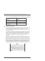

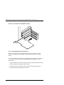

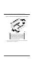
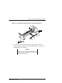

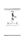

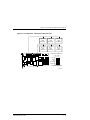


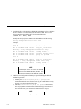


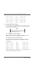


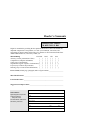


![[TD 2669-CR] Tru64 UNIX Support of Elsa Gloria Synergy](http://vs1.manualzilla.com/store/data/007442235_1-25d13c2c2fac7dc7a07b7bddfb43f1df-150x150.png)