1
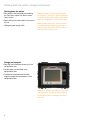
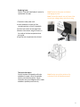
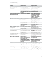
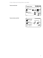
User Manual
V2.1
TRIGEN™ SURESHOT™ Distal Targeting System
User Manual
Table of Contents
Introduction............................................................................................2
Glossary of symbols...............................................................................3
Warnings and cautions..........................................................................4
Quick start guide....................................................................................6
Applied parts for targeting.....................................................................7
Surgical procedure – OR preparation....................................................8
Surgical procedure – After IM nail assembly to the drill guide..............10
Surgical procedure – Freehand interlocking..........................................14
Navigation screen operation..................................................................17
Shutting down the system, storage and transport.................................18
Maintenance..........................................................................................19
Service....................................................................................................22
Troubleshooting......................................................................................23
Product label and transportation case label..........................................25
Technical specifications.........................................................................26
Parts and accessories list......................................................................27
Guidance and manufacturer’s declaration –
Electromagnetic emissions, immunity and separation distances..........28
Warranty.................................................................................................33
Service replacement units warranty.......................................................33
Service replacement program................................................................34
Repair service program..........................................................................34
Manufacturer
Smith & Nephew Orthopaedics
1450 Brooks Rd.
Memphis, TN 38116
USA
1-901-396-2121
www.smith-nephew.com
1
Introduction
Legend
Important warnings appear in orange
Tips, tricks and important information appear
in blue
Indications, contraindications, intended use and training
The Smith & Nephew TRIGEN™ SURESHOT™ Distal Targeting System is intended to
be an intraoperative image-guided localization system. It is a computer-assisted
orthopaedic surgery tool to aid the surgeon with drill positioning for screws during
intramedullary nail implantation. It provides information to the surgeon that is used
to place surgical instruments during surgery utilizing intraoperatively obtained
electromagnetic tracking data. The Smith & Nephew TRIGEN SURESHOT Targeting
System V2.1 is indicated for long bone fractures treated with intramedullary nails in
which the use of stereotactic surgery may be appropriate.
An example of a surgical procedure includes but is not limited to locating and
drilling the distal holes in an intramedullary nail.
Contraindications
The screw targeting software application for this system is contraindicated for all IM
nails other than Smith & Nephew TRIGEN META-NAIL, TAN, FAN, Humeral, Pediatric
and Adolescent nails. Do not operate the TRIGEN SURESHOT Targeter within
200mm of an installed pacemaker. The magnetic field produced by the Targeter
may interfere with the operation of the pacemaker.
Intended use
The TRIGEN SURESHOT Distal Targeting System is only designed for use with the
indicated implants and instruments. Implants and instruments must be used in
accordance with the instructions, as described in this manual and/or in the
non-navigated surgical procedure.
Training
Only trained operators are allowed to use the TRIGEN SURESHOT Distal Targeting
System. The various operating instructions must be fully read and understood as
part of the training. If any part of the instructions is not clear, please contact your
local representative.
Plausibility check
As with all technical equipment, malfunctions may occur due to improper use
or, more rarely, technical failure. To reduce the risks involved with such technical
malfunction the operation can be completed using manually controlled instruments,
providing the malfunction is detected without delay.
It is, therefore, important to check the plausibility of the steps, as indicated by the
system, and to carry out verification of the software targeting, particularly when
using the system for the first time. Should there be any doubt regarding correct
functioning, the targeting should be verified or a switch made to a traditional
X-Ray technique.
2
Glossary of symbols
Trauma Interface
Kommunikationsschnittstelle für Trauma • Interfaz de trauma • Interface trauma • Interfaccia
Trauma • Traumagränssnitt • Trauma-interface • Interface para Traumatismo • Traumeinterface •
Traumegrensesnitt
Consult instructions for use
0086
71692802
2X
T3.15A 250V
5 x 20mm
100-240V~, 50/60 Hz
2.2A
Smith & Nephew, Inc.
Memphis, TN 38116 USA
www.smith-nephew.com
Tel: (901) 396-2121 International
(800) 238-7538 USA Customer Service
MEDICAL ELECTRICAL
EQUIPMENT WITH RESPECT
TO ELECTRICAL SHOCK, FIRE,
AND MECHANICAL HAZARDS.
Equipment classification – Patient Isolation/Type BF Applied Part
4000207
Power ON (connection to the mains)
Patents Pending
81068350 Rev. C
Power OFF (disconnection from the mains)
Catalog number
Serial number
Testing Lab certification
Fuse
T3.15A 250V
5 x 20mm
0086
Made in USA
RECOGNIZED
COMPONENT
CE Mark
Temperature range
Humidity limit
EU Not for general waste
European representative
3
Warnings and cautions
Accessibility of documentation
Please ensure that all instructions are kept in an easily accessible place for
operating personnel.
The operator checks and decides
All the information provided by the TRIGEN™ SURESHOT™ Distal Targeting System is to
help the operator make decisions during the operation. The operator must check all
the suggestions made by the system and is responsible for all decisions taken.
Responsibility of Smith & Nephew Orthopaedics
In the event of improper use, Smith & Nephew accepts no responsibility or liability
whatsoever for the functioning or utility of the TRIGEN SURESHOT Distal Targeting
System when used in the operating theatre.
Cleaning and sterilization
All instruments must be sterilized before use. Detailed information on the cleaning
and sterilization of components is contained in the separate Cleaning and
Sterilization Instructions (Smith & Nephew document 7138-1339).
Repair or modifications to the system
The user is not permitted to modify or service the equipment. There are no
serviceable parts inside the unit. Refer all service to authorized personnel.
Modifications/additions to the software
The user is not permitted to install or uninstall software. Any new software must be
installed by the manufacturer or by authorized personnel.
It is only allowed to connect equipment to the interface and power supply
connections of the TRIGEN SURESHOT Distal Targeting System which are IEC60601-1
approved and which are approved by Smith & Nephew Orthopaedics. Do not
modify this equipment without authorization of the manufacturer.
Electrical safety warning
To avoid risk of electric shock, this equipment must only be connected to a supply
mains with protective earth (=ground).
Avoid spilling water or other liquids on electronic/electrical equipment.
Use only Smith & Nephew disposables and accessories with the Smith & Nephew
TRIGEN SURESHOT Distal Targeting System
Maintenance
To verify accurate functionality, the device should be checked per the Maintenance
section of this document (beginning on page 19). This accuracy check must be
performed at least once every 12 months.
If this accuracy check is not performed as defined in the previous paragraph, all
warranty claims expire and the device is operated at the user’s own risk.
Recycling
Old electrical and electronic equipment must be disposed separately and may not
be included in the regular domestic waste. Alternatively, the unit can be handed
over to Smith & Nephew Orthopaedics for correct recycling.
4
Note Do not unplug the power while the system
is running!
Note Danger of damage and tipping over!
Tip Place the unit on a firm, level surface capable
of holding at least 10kg (22 lbs).
Note To avoid the risk of electric shock,
this equipment must only be connected to a
supply mains with protective earth.
5
Quick start guide
Where to find the components
2
1
Trauma Interface (Cat. No. 7169-2802)
2 Power cord (country specific)
1
Front panel layout
1
Probe sensor ports
2 Targeter port
3
3 Touch screen interface
1
2
Rear panel layout
1
5
Power switch
2 Power connection
3 USB connections (service only)
4 VGA video output (1024 x 768 resolution)
5 VESA mounting posts (10-32 thread pitch, 100mm
screw pattern)
1
2
6
3
4
Applied parts for targeting
TRIGEN™ SURESHOT™ Targeter
(Body Applied Part Type BF)
Note The Targeter will be operated within the
sterile field and may have contact with the skin
of the patient. The drill sleeve inserts will be used
in the incision and have direct bone contact.
Note Verify that the Targeter housing is not
damaged (holes, tears, cracks). If the housing
or the connector is damaged, the Targeter is no
longer safe to use.
Note If the Targeter is not recognized after
its connection to the system, the Targeter is
defective and must be exchanged. (See also
instrument connection).
Note Broken or damaged instruments must
be exchanged immediately and sent back to
Smith&Nephew, Inc.
Note This device is provided non-sterile and
must be cleaned and sterilized per Cleaning
and Sterilization (Smith & Nephew document
7138-1339) prior to use.
TRIGEN SURESHOT Probes
(Body Applied Part Type BF)
TRIGEN SURESHOT META-NAIL™ Standard Drill Guide Probe
Note The probe will be used as an intramedullary
tool inside the nail placed in the patient’s bone.
Note If the probe is not recognized after its
connection to the system, the probe is
defective and must be exchanged. (See also
instrument connection).
Note Broken or damaged instruments must
be exchanged immediately and sent back to
Smith & Nephew, Inc.
Note This device is provided sterile by ethylene
oxide gas and is single use.
Note In case the packaging is compromised,
please replace with new sterile packaged probe.
7
Surgical procedure – OR preparation
Note This procedure will cover only the specific steps of freehand targeting of intramedullary locking
holes using the TRIGEN™ SURESHOT™ Distal Targeting System. For the full surgical procedure, please
refer to the specific surgical technique for the TRIGEN IM Nail System being implanted.
Trauma Interface setup
After the sterile areas have been established,
place the Trauma Interface (7169-2802) in the
desired non-sterile location and turn on the
power switch.
When start-up screen disappears before the
display prompts for tool connections, a warning
screen will appear: Do not operate the TRIGEN
SURESHOT Targeter within 200mm of an installed
pacemaker.
The magnetic field produced by the Targeter may
interfere with the operation of the pacemaker.
8
Tip If the Trauma Interface does not power on,
make sure the switch is in the “on” position.
Note No other electrical devices should be
placed near the Trauma Interface. See the
“Guidance and Manufacturer’s Declaration –
Separation Distances” table at the end of
this document.
TRIGEN™ SURESHOT™ Targeter connection
When the display prompts for tool connections,
connect the TRIGEN SURESHOT Targeter
(7169-2801) to the Targeter port on the
Trauma Interface.
Note The Targeter body may have contact with
the patient and must remain in the sterile field at
all times. Only the cable and connector may be
removed from the sterile field.
Note This step needs to be performed at least
ten minutes prior to targeting in order to ensure
proper accuracy.
Tip When oriented as shown, the connector
should assemble easily. Do not force the
connector into the port.
Note If the Targeter is properly connected to the
system and the application remains in this screen
for more than 30 seconds, the Targeter may have
been damaged during cleaning/sterilization. In
this case another Targeter has to be used.
Tip It is possible at any time to disconnect and
reconnect tools when the application is running.
The display will show a screen reporting the
missing instrument.
Confirmation that the targeter tool has
been connected when the center of the
Targeter lights up orange.
9
Surgical procedure – After IM nail assembly to the drill guide
Probe selection and assembly
Assemble the appropriate probe and set stop
for the TriGEN™ IM nail and drill guide that will
be used.
Note Proper orientation of the probes to the set
stops as shown is required. Failure to do so may
result in inaccurate targeting.
TRIGEN SURESHOT™
META-NAIL™
Standard Drill
Guide Probe
(7169-2814)
TRIGEN SURESHOT
META-NAIL
Semi-extended
Drill Guide Probe
(7169-2803)
TRIGEN SURESHOT
Percutaneous
TAN™/FAN Drill
Guide Probe
(7169-2815)
TRIGEN SURESHOT
Humeral Nail Drill
Guide Probe
(7169-1152)
Red probe
Use only with
META-NAIL
Standard Drill Guide
Blue probe
Use only with
META-NAIL
Semi-extended
Drill Guide
Green probe
Use only with
Percutaneous
TAN/FAN Drill Guide
(7163-1021)
Dark Green probe
Use only with
Humeral Drill Guide
(7175-1129)
Set the probe to the length of the TriGEN IM nail.
For META-NAIL, notches
should face anteriorly
10
For TAN/FAN, notches
should face medially
For Humeral, notches
should face laterally
Probe connection
Connect the probe to either of the probe sensor
ports on the Trauma Interface.
Tip When oriented as shown, the connector
should assemble easily. Do not force the
connector into the port, simply try rotating the
connector until the keys are oriented in the
12 o’clock position.
Note If the probe is properly connected to the
system and the application reports “Probe not
found” for more than 10 seconds, the probe may
be damaged or defective. In this case, the probe
has to be exchanged.
Confirm that the tool connection has
been verified.
Drill sleeve selection
Select the length of the drill sleeve (7169-2804 or
7169-2805) that will be used.
Tip It is possible at any time to disconnect and
reconnect tools when the application is running.
The display will show a screen reporting the
missing instrument.
Tip A different sleeve can be selected at any
time during the procedure by choosing the drill
sleeve option from the drop down menu after the
implant has been selected. The selected sleeve
will be noted on the navigation screen.
Note For Humeral Nails, there is only one option
provided for the drill sleeve (7169-1154)
11
Implant selection screen
Select the TriGEN™ IM nail and size that will
be used.
Tip A different TriGEN IM nail and/or size can
be selected at any time during the procedure by
choosing the Implant option from the drop down
menu. The selected implant and diameter will be
noted on the navigation screen.
Or
For TRIGEN Humeral Nail: Select the TRIGEN
Humeral nail size that will be used.
Tip A different TRIGEN Humeral Nail size can be
selected at any time during the procedure by
choosing the implant option from the drop down
menu. The selected implant and diameter will be
noted on the trauma interface screen.
Drill sleeve attachment
Tightly secure the selected drill sleeve to
the Targeter.
Tip The drill sleeve (7169-2804 or 7169-2805) can
be loosened from the Targeter using the slot in
the TriGEN Hammer (7167-4082).
Tip The drill sleeve (7169-1154) can be loosened
from the targeter using the slot in the TRIGEN
Slotted Hammer (7175-1135).
12
Locking hole accuracy check in the
operative field
Insert the probe with the assembled set stop
through the drill guide and cannulation of the
TRIGEN™ IM nail.
Attach the set stop to the drill guide, ensure that
the probe is oriented correctly and the set stop
position and IM nail length match.
Note The TRIGEN SURESHOT™ Distal Targeting
System cannot be used with the META-NAIL™
Extension Drill Guide (7165-4503) or the
Standard TriGen Drill Guide (7163-1134).
Note All tool cables should be uncoiled
completely and any excess cables should be
kept out of the Targeter measurement volume.
Note To guarantee system accuracy, the
accuracy check has to be performed directly
in the operative field.
For META-NAIL,
notches should
face anteriorly
For TAN™/FAN,
notches should
face medially
For Humeral nail,
notches should
face laterally
Use only with
Meta Standard or
Semi-Extended Drill
Guide 7165-4502 or
7165-4524
Use only with
Percutaneous TAN/
FAN Drill Guide
7163-1021
Use only with
Humeral Drill Guide
Probe (7169-1152)
Place the IM nail with inserted probe directly
beside the patient’s limb. Position the Targeter
over the locking holes and verify the accuracy
on the Trauma Interface.
Optional – Field accuracy check
An optional field accuracy check can be
performed at this point using the instructions in
the Maintenance section.
Note This step should be performed at least
once a year to ensure that the device is
working properly.
13
Surgical procedure – Distal Targeting
Note When the Targeter is out of the preferred range or there is metal or electrical interference, the
green and red Targeter circles on the navigation screen may become unstable and/or a warning
message will be displayed. If the interference is excessive, the IM nail image on the navigation screen
will disappear. If interference cannot be avoided, a standard X-Ray technique must be used.
Note All tool cables should be uncoiled completely and any excess cables should be kept out of the
Targeter measurement volume.
Probe and set stop insertion
Following the removal of the Ball Tip Guide Rod,
insert the probe and set stop into the IM nail
as described in the locking hole accuracy
check on the previous page.
Skin incision
Position the serrated tip of the drill sleeve
(represented by the green circle) over the desired
locking hole and make the initial incision.
Note Reference the warnings and tips in
the locking hole accuracy check on the
previous page.
Tip If performing this procedure using any of the
TriGEN™ femoral antegrade nails (TAN™/FAN/
Pediatric/Adolescent), the Anteversion Locking
Guide (7169-2816) should be used along with a
4.0mm Drill Sleeve/Drill Bit to keep the IM nail
from rotating.
Targeting the locking hole
With the appropriate length TRIGEN
SURESHOT™ 4.0mm Drill Bit (7169-2810 or
7169-2811) or the TRIGEN SURESHOT Humeral
AO Drill Bit (7169-1155) inserted into the Targeter,
insert the tip of the drill sleeve (represented by
the green circle) through the incision and down
to bone.
Critical Verify there are no other metal
objects (including metal triangles) in the field.
Metal interference will cause the system to
be inaccurate.
14
Adjust the trajectory of the Targeter (represented
by the red circle) until both the green and red
circles are concentric and drill through to the
far cortex.
Note The green ring must be fully within the hole
of the IM nail displayed on the navigation screen
to ensure accurate drilling.
The accuracy may be verified using the C-arm.
Note The standard TriGEN™ drill bits are made
from magnetic stainless steel that will cause
interference with the system and cannot be used.
Be sure to use the gold non-magnetic TRIGEN
SURESHOT™ drill bit or long gold non-magnetic
drill bit.
Length measurement
Before drilling through the far cortex, measure
the length using the calibrations on the TRIGEN
SURESHOT 4.0mm Drill Bit or the TRIGEN
SURESHOT Humeral AO Drill Bit (7169-1155).
Tip After measuring the length on the drill
bit prior to drilling the far cortex, add the
appropriate screw length in order to account
for the thickness of the far cortex. Ensure the
Targeter and the sleeve are pushed against
the bone.
Alternatively, the length measurement can be
achieved using the standard Screw Length Gauge
(7163-1189) through the Targeter after removing
the drill sleeve.
Screw insertion
Using the TRIGEN SURESHOT Hexdriver
(7169-2809 or 7169-1153), the screw may be
inserted using the Targeter.
Tip If the Targeter is placed too close to the
bone, the image of the IM Nail on the display
might disappear.
Note The standard TriGEN Hexdrivers are made
from magnetic stainless steel that will cause
interference with the system and cannot be used.
15
The depth of the screw can be verified by
placing a 9.0mm Gold Drill Sleeve (7163-1152 or
7175-1128) down to bone over the hexdriver. The
screw head will be flush with bone when the
groove on the hexdriver is even with the end of
the 9.0mm Gold Drill Sleeve.
The positioning of the screw may be verified
using the C-arm.
16
Navigation screen operation
Overview mode
When the Targeter is greater than 5cm from the
interlocking holes, the navigation screen will
display the IM nail in the overview mode. This
provides the user with a larger field of view in
order to help find the general location of the
interlocking holes.
Note If the desired hole in the nail is not oriented
to be viewed on the screen, then the orientation
of the Targeter is not aligned closely enough
to that specific hole. Try holding the Targeter
generally AP or generally ML to orient the
desired view.
Drilling mode
When the Targeter is moved within 5cm of the
interlocking holes, the navigation screen will
display the IM nail in the drilling mode. This
provides the user with a smaller field of view that
automatically zooms in to the interlocking holes.
The white lines displayed on either side of the IM
nail can be used for targeting blocking screws.
These lines are located 2.5mm from the side of
the IM nail for all IM nails 10mm and larger in
diameter. These lines are located 2mm from the
sides of 8.5mm IM nails.
Drilling mode manual rotation
Each IM nail has several predefined views
that are automatically selected depending
on the position of the Targeter to the IM nail.
Depending on the operating environment, these
predefined views might not be appropriate and
can be manually adjusted.
To rotate the view
Touch the screen near the outside and “drag” the
view in a clockwise or counterclockwise direction.
To flip the view
Touch the “Menu” button and select “Toggle
Back View.”
All changes made for a view are temporarily
stored for that view until program exit.
To reset the view
The default view settings can be restored by
touching the “Menu” button and selecting “Reset
View” or double tapping the center of the screen.
17
Shutting down the system, storage and transport
Shutting down the system
•Shut down the Trauma Interface by selecting
the “Shut Down” option from the on-screen
“Menu” button.
•Switch off the main power switch on the rear of
the unit.
•Unplug the power supply cable.
Note Shut down the Trauma Interface using
the on-screen “Shut Down” option and wait for
the system to power down before switching off
power or unplugging from main power supply.
Note The internal fan of the Trauma Interface
runs continuously whenever the rear power
switch is in the ON position. Switch power off
whenever the unit is not in use.
Storage and transport
•Place the Trauma Interface (screen up) in the
transportation case.
•Coil the power cord and store in the
transportation case.
•Consider the temperature and humidity
range for storage and transportation on the
transportation case.
Caution Do not place any objects on top of the
screen when the Trauma Interface is stored in
the shipping container. Damage to the screen
may occur.
18
Maintenance
Field accuracy check
A field accuracy check procedure should be
performed at least once a year or whenever
the accuracy of a TRIGEN™ SURESHOT™ probe or
TRIGEN SURESHOT Targeter needs to be
verified. This procedure can also be
performed during surgery to verify all
components are working correctly prior to their
use on a patient.
Field accuracy check steps
Attach TRIGEN SURESHOT Field Accuracy Gauge
(7169-2808) to TRIGEN SURESHOT Targeter. The
knob on the Field Accuracy Gauge should be
hand tightened only.
1
2 Attach the META Set Stop (7169-2806) to the end
of the Field Accuracy Gauge, insert a TRIGEN
SURESHOT probe into the set stop and set the
depth to the “REF” mark on the probe body.
3 From the software “Menu” button, select “Field
Check” option.
19
4 A software window will appear informing
the user if the TRIGEN™ SURESHOT™ Targeter and
Probe combination is within the
predefined accuracy parameters (“Pass”
or “Fail” message).
5 If the field accuracy check fails, check the
“Troubleshooting” section of this document for
possible solutions.
Software upgrades
Software upgrades are performed using a
Smith & Nephew, Inc. supplied USB memory
stick and a Work Instruction document. The Work
Instruction document should be filled out and
returned to Smith & Nephew Customer Service
upon completion.
Cleaning and disinfection
The TRIGEN SURESHOT Trauma Interface is used
in the non-sterile area of the operating theatre
and is cleaned and disinfected using commercial
cleaning and disinfectant products such as a mild
detergent and water or a bactericidal cleaning
Note Observe the manufacturer’s instructions for
solution such as 70% isopropyl alcohol.
dilution, exposure time, etc.
Care must be taken not to allow any liquid to
Note DO NOT sterilize with ethylene oxide gas or
pass into any electrical connections or the
steam sterilize the Trauma Interface.
interior of the unit. Let the surfaces dry
Note Probes are NOT reusable.
thoroughly before plugging in the unit. DO NOT
steam sterilize the system. DO NOT submerge
the system for any reason.
All other reusable instruments shall be cleaned
and sterilized according to the Cleaning and
Sterilization Instructions (Smith & Nephew
document 7138-1339).
20
Replacing fuses
See the “Technical Specifications” section for
replacement fuse type.
Note Disconnect the power cord before
exchanging any fuse.
Note To avoid fire hazard, use only fuses of the
correct type, voltage rating, and current rating.
1
Disconnect main power cord.
2 Use a screwdriver to open the fuse
compartment door on the AC receptacle.
3 Pull out fuse carriers to exchange fuses.
4 Reinsert fuse carriers using the arrows on
the inside of the fuse compartment door
as a guide.
5 Snap the fuse compartment door closed.
Technical information
Smith & Nephew Orthopaedics will make
available on request a list of all repairable
exterior parts with descriptions. Interior
schematics and circuit diagrams will be made
available to qualified personnel only.
Note Service can only be performed by
authorized Smith & Nephew personnel.
21
Service
TRIGEN™ SURESHOT™ Distal Targeting
System service philosophy
There are no user-serviceable components inside
the TRIGEN SURESHOT Trauma Interface. Repairs
and adjustments are to be performed only by
Smith & Nephew authorized service centers.
If service becomes necessary, call your
authorized Smith & Nephew customer service
representative prior to returning the device and
request a Return Authorization (RA) number.
Your representative can also explain the available
service replacement and repair programs.
The device should be packaged in its original
transportation case and returned postage paid.
Your Smith & Nephew customer service
representative will provide additional instructions
for shipment.
Electrical interference
This equipment is designed and tested to
minimize interference with other electrical
equipment. However, if interference occurs
with other equipment, it may be corrected by
one or more of the following measures:
•Reorient or relocate this equipment, the other
equipment, or both.
•Increase the separation between the pieces
of equipment.
•Connect the pieces of equipment into different
outlets or circuits.
•Consult a biomedical engineer.
Environmental protection
This equipment contains electronic printed
circuit assemblies. At the end of the useful life
of the equipment, it should be disposed of in
accordance with any applicable national or
institutional related policy relating to obsolete
electronic equipment.
22
Note Product returned that is found to have been
serviced by an unauthorized third-party repair
facility and/or sterilized with a sterilization method
other than one approved by Smith & Nephew
will incur additional costs, regardless of
warranty status.
Troubleshooting
Problem
Trauma Interface unit is
without power
Buttons or items are difficult to
select on the touchscreen
VGA video out not functioning
Possible cause
Mains power plug is not
inserted (properly) or there is
no mains power
No power on the wall outlet
Probe not recognized
Probe will not insert to the
proper depth in the nail
Nail not visible on the screen
Drill bit too short
Drill bit too long
Try other power outlet
One or both mains power fuses Replace mains fuses
are blown
Touchscreen is de-calibrated
Access calibration software
by selecting “Maintenance”
from the “About” option
under the “Menu” options
(password required)
VGA port not activated on
Connect VGA cable to both
Trauma Interface
Trauma Interface and video
monitor before powering on
Trauma Interface
Damaged VGA cable
Replace VGA cable
Video monitor not on
correct input
TRIGEN™ SURESHOT™ Targeter
not recognized
Suggested action
Insert mains power plug into
reliable power supply
Select proper input on
video monitor
Error reading data from Targeter Unplug Targeter, wait
10 seconds, plug back in
Damaged Targeter
Replace Targeter with new unit
Error reading data from probe
Unplug probe, wait 10 seconds,
plug back in
Damaged probe
Replace probe with new unit
Obstruction within the
Re-insert the ball tip guide rod
nail cannulation
into the nail cannulation to clear
any obstruction
Metal interference
Remove any metal objects from
within the TRIGEN SURESHOT
the targeting field
electromagnetic field
TRIGEN SURESHOT Targeter
Move the TRIGEN SURESHOT
and probe not within range of
Targeter closer to the sensor
each other
end of the probe
Short drill bit being used and
Press “Menu”, “Drill Sleeve”
long drill sleeve option selected and select the short drill
within software
sleeve option and use the
short drill bit
Long drill bit being used
Press “Menu”, “Drill Sleeve”
and short drill sleeve option
and select the long drill sleeve
selected within software
option and use the long drill bit
23
Problem
Possible cause
Red and Green targeting circles Incorrect drill sleeve
representing the drill sleeve
length selected
appear incorrect
Metal interference within
the TRIGEN™ SURESHOT™
electromagnetic field
Probe not inserted correctly
within set stop
Damaged probe
Targeting missed the
intended hole
Metal interference
within the TRIGEN SURESHOT
electromagnetic field
Probe not inserted correctly
within set stop
Damaged probe
Drill sleeve cannot be
removed from TRIGEN
SURESHOT Targeter
Over-tightening of drill sleeve
The 4.7mm/4.0mm step drill will Not compatible with
not fit through the drill sleeve
the TRIGEN SURESHOT Distal
Targeting System
Field accuracy check fails
Metal interference within
the TRIGEN SURESHOT
electromagnetic field
Field Accuracy Gauge
improperly installed
on Targeter
META Set Stop improperly
installed on Field
Accuracy Gauge
Probe is incorrectly inserted
within META Set Stop
Probe is damaged
Targeter is damaged
24
Suggested action
Verify the correct drill sleeve
length is selected from the
software menu
Remove any metal objects from
the targeting field
Verify probe is oriented and
seated correctly in the notches
of the set stop
Verify probe accuracy with Field
Accuracy Gauge
Remove any metal objects from
the targeting field
Verify probe is oriented and
seated correctly in the notches
of the set stop
Verify probe accuracy with Field
Accuracy Gauge
Use the Slotted Hammer from
the instrument tray as a wrench
to unscrew the drill sleeve
counter-clockwise from
the Targeter
Only use the long (7169-2811)
and short (7169-2810) drills
designated for use with
the TRIGEN SURESHOT Distal
Targeting System
Remove any metal objects from
the targeting field
Verify Field Accuracy Gauge is
fully seated within Targeter port
and knob is hand tightened
to Targeter
Verify META Set Stop
is correctly oriented and
tightened securely to Field
Accuracy Gauge
Verify probe is oriented
properly and inserted to the
“REF” notches on probe body
Replace probe with a new probe
Replace Targeter with a new
Targeter and return old one
for service
Product label and transportation case label
Trauma Interface label
Trauma Interface
71692802
2X
T3.15A 250V
5 x 20mm
SERIAL
NUMBER
100-240V~, 50/60 Hz
2.2A
FUSE
SEE INSERT
RECOGNIZED
COMPONENT
Smith & Nephew, Inc.
Memphis, TN 38116 USA
www.smith-nephew.com
Tel: (901) 396-2121 International
(800) 238-7538 USA Customer Service
SHOCK
PROTECTION
TYPE BF
MEDICAL ELECTRICAL
EQUIPMENT WITH RESPECT
TO ELECTRICAL SHOCK, FIRE,
AND MECHANICAL HAZARDS.
NOT FOR
GENERAL
WASTE
4000207
Made in USA
81068350 Rev. D
Trauma Interface case label
*smith&nephew
Trauma Interface Case
CATALOG
NUMBER 71692817
Storage and Transport
Contains:
CATALOG
NUMBER
71692802
Dimension 63 x 50 x 35 cm
(DxWxH) 25 x 20 x 14 in
Weight
20KG / 44 lb
90%
50°C
122°F
Trauma Interface
-20°C
-4°F
HUMIDITY
LIMIT
TEMP
LIMIT
10%
0086
CATALOG
NUMBER
0086
Kommunikationsschnittstelle für Trauma • Interfaz de trauma • Interface trauma • Interfaccia
Trauma • Traumagränssnitt • Trauma-interface • Interface para Traumatismo • Traumeinterface •
Traumegrensesnitt
81068365 Rev. B
25
Technical specifications
System power supply
Fuses
Classification
Voltage
Frequency
Connected load
Type
Quantity
Protection class
100–240 VAC
50–60 Hz
≤ 2.2 Amps
T3.15A L 250V
2
Class I (with protective earth [=ground])
IPX0, continuous operation
Ambient conditions
Storage and transport
System
Transportation case
System + case + accessories
Complies with standards
Type
Humidity
Explosion
Temperature
Humidity
Air pressure
Temperature
Humidity
Air pressure
Dimensions (DxWxH)
Weight
Dimensions (DxWxH)
Weight
BF (with hand-held FG, targeting probe)
No protection
No protection
10–40°C
30–75% RH (non-condensing)
700–1060 HPa
-20–50°C
(in original packaging)
10–90% RH (non-condensing)
700–1060 HPa
40cm x 38cm x 20cm
9kg
63cm x 50cm x 35cm
≈ 20kg
USA, Canada, Europe
IEC 60601-1 (2nd edition)
IEC 60601-1-2:2007
CSA C22.2#601-1 (2nd edition)
Electrical safety
The system meets IEC standards (eg IEC 60601). All configurations comply with standard
IEC 60601-1-1. Any person connecting equipment to the system is responsible for the configuration
and must ensure that it complies with system standard 60601-1-1 or equivalent national standards.
Please contact your customer service representative in the event of any queries.
Note The system may reboot after a power line surge greater than 1KV. This is considered a normal
condition and the system will automatically reboot to the software application.
Note Only use 110V/60Hz AC connection when powering the Trauma Interface within the United
States. The Trauma Interface is not certified for 220V/60Hz operation within the United States.
Note This equipment is not suitable for use in the presence of a flammable anesthetic mixture with
air, oxygen, or nitrous oxide.
Note To ensure proper operation, no other electrical components should be located near the
TRIGEN™ SURESHOT™ Distal Targeting unit.
Smith & Nephew reserves the right to make any technical changes.
26
Parts and accessories list
Catalog No.
7169-1151
7169-1153
7169-1154
7169-1156
7169-1152
7169-1155
7169-2801
7169-2802
7169-2803
7169-2804
7169-2805
7169-2806
7169-2807
7169-2808
7169-2809
7169-2810
7169-2811
7169-2814
7169-2815
7169-2816
7169-2817
7169-2819
7169-2830
7169-2831
6680-0193
6680-0291
6680-0213
6680-0303
6680-0302
Description
TRIGEN™ SURESHOT™ Humeral Set Stop
TRIGEN SURESHOT Humeral 3.5mm Hexdriver
TRIGEN SURESHOT Humeral 3.2mm Drill Sleeve
TRIGEN SURESHOT Humeral Instrument Caddy
TRIGEN SURESHOT Humeral Drill Guide Probe
TRIGEN SURESHOT Humeral 3.2mm AO Drill
TRIGEN SURESHOT Targeter
Trauma Interface
TRIGEN SURESHOT META-NAIL™ Semi-extended
Drill Guide Probe
TRIGEN SURESHOT Long Drill Sleeve
TRIGEN SURESHOT Short Drill Sleeve
TRIGEN SURESHOT META Set Stop
TRIGEN SURESHOT Percutaneous TAN™/FAN Set Stop
TRIGEN SURESHOT Field Accuracy Gauge
TRIGEN SURESHOT Hexdriver
TRIGEN SURESHOT Short AO Drill
TRIGEN SURESHOT Long AO Drill
TRIGEN SURESHOT META-NAIL Standard Drill Guide Probe
TRIGEN SURESHOT Percutaneous TAN/FAN Drill
Guide Probe
TRIGEN SURESHOT TAN Anteversion Locking Guide
Trauma Interface Case
TRIGEN SURESHOT TAN Set Stop Bolt
TRIGEN SURESHOT Distal Targeting Instrument Tray
TRIGEN SURESHOT Distal Targeting Instrument Tray Lid
Power Cord, 125 Volt 10 AMP, North America (Hospital Grade)
Power Cord, 250 Volt 10 AMP, Continental Europe
Power Cord, 250 Volt, 10 AMP, UK
Power Cord, 250 Volt, 10 AMP, Australia/New Zealand
Power Cord, 250 Volt, 10 AMP, South Africa/India
Caution Inspect all components regularly for wear.
Caution Use only Smith & Nephew disposables and accessories with the
Smith & Nephew TRIGEN SURESHOT Distal Targeting System.
Caution The TRIGEN SURESHOT probes are defined as single use items. The risk
of reuse includes, but is not limited to, cross contamination between patients, probe
malfunction and probe breakage. After use, the probe should be discarded per
hospital policy/procedures for biohazard material disposal.
27
Guidance and manufacturer’s declaration –
Electromagnetic emissions, immunity and separation distances
Changes or modifications to this system not expressly approved by the manufacturer may result in
increased emissions or decreased immunity performance of the equipment or system and could
cause EMC issues with this or other equipment. This system is designed and tested to comply with
applicable regulations regarding EMC and shall be installed and put into service according to the
EMC information stated as follows.
Note Use of portable phones or other radio frequency (RF) emitting equipment near the system may
cause unexpected or adverse operation.
Note The presence of certain metal objects within the electomagentic tracking volume system may
cause unexpected or adverse operation.
Note The equipment or system shall not be used adjacent to, or stacked with, other equipment.
If adjacent or stacked use is necessary, the equipment or system shall be tested to verify normal
operation in the configuration in which it is being used.
Note The use of accessories, transducers and cables other than those specified may result in
increased emissions or decreased immunity performance of the equipment or system.
Compliant cables and accessories
The table below lists cables, transducers, and other applicable accessories for which the
manufacturer claims EMC compliance.
Note Any supplied accessories that do not affect EMC compliance are not listed.
Part No.
7169-1152
7169-2801
7169-2814
7169-2815
7169-2803
28
Type
Sensor
Field Generator
Sensor
Sensor
Sensor
Description
Humeral Drill Guide Probe
TRIGEN™ SURESHOT™ Targeter
META-NAIL™ Standard Drill Guide Probe
Percutaneous TAN™/FAN Drill Guide Probe
META-NAIL Semi-extended Drill
Guide Probe
Guidance and manufacturer’s declaration – electromagnetic emissions
The TRIGEN SURESHOT Distal Targeting System is intended for use in the electromagnetic environment
specified below. The customer or the user of PiGalileo should assure that it is used in such an environment.
Emission test
Compliance
Electromagnetic environment - guidance
RF emissions
CISPR 11
Group 1
The TRIGEN SURESHOT Distal Targeting System uses RF
energy only for its internal function. Therefore, its RF
emissions are very low and are not likely to cause any
interference in nearby electronic equipment.
RF emissions
CISPR 11
Class A
Harmonic emissions
IEC 61000-3-2
Class A
Voltage fluctuations / flicker
emissions
IEC 61000-3-3
The TRIGEN SURESHOT Distal Targeting System is
suitable for use in all establishments other than domestic
and those directly connected to the public low-voltage
power supply network that supplies buildings used for
domestic purposes.
Complies
29
Guidance and manufacturer’s declaration – electromagnetic immunity
The TRIGEN SURESHOT Distal Targeting System is intended for use in the electromagnetic environment specified below. The
customer or the user of PiGalileo should assure that they are used in such an environment.
IEC 60601
test level
Immunity test
Electrostatic
discharge (ESD)
IEC 61000-4-2
Electrical fast
transient / burst
IEC 61000-4-4
Surge
IEC 61000-4-5
Voltage dips, short
interruptions and
voltage variations on
power supply lines
IEC 61000-4-11
Power frequency
(50/60 Hz)
magnetic field
Compliance
level
±6 kV contact
±6 kV contact
±8 kV air
±8 kV air
±2 kV for power supply
lines
±1 kV for input/output
lines
±1 kV line(s) to line(s)
±2 kV for power supply
lines
±1 kV for input/output
lines
±1 kV differential mode
±2 kV line(s) to earth
<5 % UT
±2 kV common mode
<5 % UT
(>95% dip in UT)
(>95% dip in UT)
for 0,5 cycle
for 0,5 cycle
40% UT
(60% dip in UT)
40% UT
(60% dip in UT)
for5 cycles
for5 cycles
70% UT
(30% dip in UT)
70% UT
(30% dip in UT)
for 25 cycles
for 25 cycles
<5% UT
<5% UT
(>95% dip in UT)
(>95% dip in UT)
for 5s
for 5s
3 A/m
not tested
IEC 61000-4-8
Note: UT is the a.c. mains voltage prior to application of the test level.
30
Electromagnetic environment - guidance
Floors should be wood, concrete or ceramic tile. If
floors are covered with synthetic material, the
relative humidity should be at least 30%
Mains power quality should be that of a typical
commercial or hospital environment.
Mains power quality should be that of a typical
commercial or hospital environment.
Mains power quality should be that of a typical
commercial or hospital environment. If the user of
the table requires continued operation during
power mains interruptions, it is recommended that
the TRIGEN SURESHOT Distal Targeting System is
powered from an uninterruptible power supply or a
battery.
If image distortion occurs, it may be necessary to
position the TRIGEN SURESHOT Distal Targeting
System further from sources of power frequency
magnetic fields or to install magnetic shielding. The
power frequency magnetic field should be
measured in the intended location to assure that it
is sufficiently low.
Guidance and manufacturer’s declaration – electromagnetic immunity
The TRIGEN SURESHOT Distal Targeting System is intended for use in the electromagnetic environment
specified below.
The customer or the user of the tables should assure that they are used in such an environment.
Immunity test
IEC 60601
test level
Compliance
Level
Electromagnetic environment guidance
Portable and mobile RF communications
equipment should be used no closer to any
part of the TRIGEN SURESHOT Distal
Targeting System, including cables, than the
recommended separation distance
calculated from the equation applicable to
the frequency of the transmitter.
Conducted RF
IEC 61000-4-6
3 Vrms
150 kHz to 80 MHz
3 Vrms
Radiated RF
IEC 61000-4-3
3 V/m
80 MHz to 2,5 GHz
3 V/m
Recommended separation distance
d = 1,2
d = 1,2
80 MHz to 800 MHz
d = 2,3
800 MHz to 2,5 GHz
where P is the maximum output power rating
of the transmitter in watts (W) according to
the transmitter manufacturer and d is the
recommended separation distance in metres
(m). b
Field strengths from fixed RF transmitters as
determined by an electromagnetic site
survey, a
should be less than the compliance level in
each frequency range. b
Interference may occur in the vicinity of
equipment marked with the following
symbol:
NOTE 1
At 80MHz and 800MHz, the higher frequency range applies.
NOTE 2
These guidelines may not apply in all situations. Electromagnetic propagation is affected by
absorption and reflection from structures, objects and people.
a
Field strengths from fixed transmitters, such as base stations for radio (cellular/cordless) telephones and
land mobile radios, amateur radio, AM and FM radio broadcast and TV broadcast cannot be predicted
theoretically with accuracy. To assess the electromagnetic environment due to fixed RF transmitters, an
electromagnetic site survey should be considered. If the measured field strength in the location in which
the TRIGEN SURESHOT Distal Targeting System is used exceeds the applicable RF compliance level
above, the patient table THS or IGS Trauma should be observed to verify normal operation. If abnormal
performance is observed, additional measures may be necessary, such as re-orienting or relocating the
TRIGEN SURESHOT Distal Targeting System.
b
Over the frequency range 150kHz to 80MHz, field strengths should be less than 10 V/m.
31
Recommended separation distances between portable and mobile RF
communications equipment and the TRIGEN SURESHOT Distal Targeting
System
The TRIGEN SURESHOT Distal Targeting System is intended for use in the electromagnetic environment in
which radiated RF disturbances are controlled. The customer or the user of the TRIGEN SURESHOT Distal
Targeting System can help prevent electromagnetic interference by maintaining a minimum distance between
portable and mobile RF communications equipment (transmitters) and the TRIGEN SURESHOT Distal
Targeting System as recommended below, according to the maximum output power of the communication
equipment.
Rated maximum output power
of transmitter
Separation distance according to frequency of transmitter
m
150 kHz to 80 MHz
80 MHz to 800 MHz
800 MHz to 2.5 GHz
W
d = 1,2
d = 1,2
d = 2,3
0,01
0,12
0,12
0,23
0,1
1
10
100
0,38
1,2
3,8
12
0,38
1,2
3,8
12
0,73
2,3
7,3
23
For transmitters rated at a maximum output power not listed above, the recommended separation distance d in
metres (m) can be estimated using the equation applicable to the frequency of the transmitter, where P is the
maximum output power rating of the transmitter in watts (W) according to the transmitter manufacturer.
NOTE 1
At 80MHz and 800MHz, the separation distance for the higher frequency range applies.
NOTE 2
These guidelines may not apply in all situations. Electromagnetic propagation is affected by
absorption and reflection from structures, objects and people.
32
Warranty
Smith & Nephew products are guaranteed to be free from defects in materials and workmanship
for the warranty period for a particular product, beginning from the date of invoice. Refer to the
current Smith & Nephew product catalog or contact Smith & Nephew customer service for specific
warranty information.
This limited warranty is restricted to repair or replacement by Smith & Nephew, at its option, of any
product found to be defective during the warranty period. Damage inflicted to a product by the
user that causes it to be unsuitable for refurbishment may result in additional charges, regardless of
warranty status. All warranties apply to the original buyer only. In no event shall Smith & Nephew be
liable for and anticipated profits, consequential damages, or loss of time incurred by the buyer with
the purchase or use of any product.
No other warranty, expressed or implied, is given.
Service replacement units warranty
The Smith & Nephew TRIGEN™ SURESHOT™ Trauma Interface replacement unit assumes the
remainder of the original unit’s warranty (if applicable). If the replacement unit is new to the customer
or replacing a unit with less than 90 days remaining on the original warranty, this unit is warranted to
be free from defects in material and workmanship for 90 days from the date of original invoice unless
otherwise provided by local law.
33
Service replacement program
Smith & Nephew offers a 48-hour Service Replacement Program for its products to minimize
downtime in your operating room. For a Return Authorization (RA) number, or for additional
information on this program, call Customer Service at 800-238-7538 US or +1-901-396-2121 INTL,
or contact your authorized representative.
Repair service program
For devices no longer under warranty, repairs can be made by Smith & Nephew or by an
authorized agent. Non-warranty repairs will be made at the list price of replacement parts plus
labor. If requested, we will provide an estimate of repair cost and time required for the repair
before any work is done. Repair items should be carefully repackaged, marked with the return
Authorization (RA) number, and returned postage-paid to the appropriate Smith & Nephew Customer
Service Center. Smith & Nephew Customer Service or your local authorized representative can
provide shipping information.
Smith & Nephew
Orthopaedics GmbH
Tuttlingen, Germany
34
Notes
35
Notes
36
0086
Orthopaedics
Smith & Nephew, Inc.
7135 Goodlett Farms Pkwy
Cordova, TN 38016
USA
www.smith-nephew.com
EC representative:
Smith & Nephew Orthopaedics GmbH
Alemannenstrasse 14
78532 Tuttlingen, Germany
Tel: 07462/208-0
Fax: 07462/208-135
Telephone: 1-901-396-2121
Information: 1-800-821-5700
Orders and Inquiries: 1-800-238-7538
™Trademark of Smith & Nephew. Certain marks Reg. US Pat. & TM Off.
©2011 Smith & Nephew, Inc. All rights reserved.
7118-1927 REVA 08/11