1
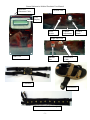
General Informative Medical Prosthetic User Manual
Introduction
Thank you for choosing the General Informative Medical Prosthetic (G.I.M.P.).
This system is designed as an accessory to a typical prosthetic leg and will assist you in
the use of your medical prosthetic by providing sensor feedback of the pressures being
placed on the bottom of the prosthetic foot. For users who are still learning to walk with
their prosthetics, the system also provides a training mode to help them learn to walk
properly
The G.I.M.P. system will help users maintain balance by monitoring four thin
pressure sensors placed in the sole of a typical shoe and a clinometer attached to the calf,
which measures the angle of the lower leg. The main control unit worn on the calf then
maps the pressures detected to the user through a cloth strap containing ten vibration
motors worn around the thigh. Depending on where pressure on the foot is detected, the
motors will vibrate at the front, back, left, and/or right side of the strap. The control
circuitry can be contained in a box strapped to the prosthetic calf, or ideally, it can be
placed in the core of the prosthetic to reduce excess bulk added to the prosthetic.
The system will also help those new to using a lower limb prosthetic device learn
to walk correctly with their prosthetic. The system has a training mode designed to teach
the user how to walk by vibrating the motor strap in a particular order to indicate to the
user which way they need to move or apply pressure to the prosthetic. In addition, the
system is capable of recording data about the device usage for review by a doctor or
therapist.
-1-
General Informative Medical Prosthetic User Manual
Motor and
Clinometer Cable
Left Side View
LCD
Display
Power
Switch
Contrast
Adjustment
Right Side View
Front View
Ethernet
Port
Foot Sensor
Cable
Clinometer
Foot Sensors
Vibration Motor Feedback Strap
-2-
Control
Knob
General Informative Medical Prosthetic User Manual
Setup Instructions
Note: These setup instructions are based on the control system residing in a box
outside of the prosthetic. If the system has been integrated into your prosthetic, setup
will not require attaching the control box and the locations of the controls and battery
may be different.
Installing the battery
Loosen the screw in the control knob and remove it. Then remove the retaining
nut from the control knob shaft. Remove the six screws securing the top of the case and
lay the top to the side, being careful not to pull out the cable attached to the LCD screen.
Remove the retaining nut from the power switch and remove it from its hole in the case.
Gently pull up on the circuit board on the side opposite the control knobs until it is free
from the case and lay it to the side as well. Place a 7.2-volt RC battery in the battery
straps located in the bottom of the case and connect it to the battery cable of the circuit
board. Replace the circuit board in the case by placing the control knob shaft through the
appropriate hole in the case and then gently pressing the opposite side of the board into
place. Replace the power switch, refasten the top of the case, and reattach the retaining
nut and control knob to the control knob shaft.
Wearing the device
Secure the control box to the calf of the leg using the straps on the back of the box.
The motor cable should be at the top of the calf. Wrap the motor feedback strap around
your thigh fastening the attached clip so that it is tight, but not so tight that it becomes
uncomfortable.
Note: The motor feedback strap may be worn over or underneath clothing but wearing
the device over thick clothing will reduce the ability to feel vibration feedback
Connect the plug of the motor strap to the motor strap cable of the control box. Then
fasten the clinometer strap to the prosthetic just below the knee making sure the
clinometer is on the side of the leg. Connect the clinometer to the control box using the
appropriate plug. Finally, put on the shoe containing the sensors and connect it to the
sensor cable of the control box.
-3-
General Informative Medical Prosthetic User Manual
Use Instructions
The General Informative Medical Prosthetic has three different modes: direct
map, training, and upload. The current mode and battery level are displayed on the LCD
located on the front of the control box. The current mode is displayed on the top line and
the battery level is indicated by the number of # symbols on the bottom line. More #
symbols indicate a stronger charge and no symbols indicate a dead battery. On startup,
the device is in direct map mode. Turning the control knob scrolls the bottom line of the
display through the modes and pressing the knob sets the mode shown as the current
mode.
In direct map mode, the device vibrates a certain pattern of motors in the feedback
strap in response to pressures detected by the sensors in the sole of the shoe. For example,
pressure on the heel of the foot will activate motors at the back of the strap while
pressures on the toe will activate motors at the front of the strap.
In training mode, the device vibrates the motors in a sequence to prompt the user
to perform the next action needed in the process of taking a step. The actions indicated
by the motor combinations are indicated in the following table.
Training Mode Motor Patterns
all motors on
lift leg
back motors on
apply pressure to heel of foot
side motors on
apply pressure to ball of foot
front motors on
apply pressure to toes
Once the sensors detect the correct action, the motors for the completed step are turned
off and the motors for the nest step of the sequence are activated.
In upload mode, the device can be connected to a computer using a standard
network crossover cable and statistics about the device usage can be viewed by a standard
web browser. Entering the IP address 192.190.2.5 in the address bar of the browser will
trigger the device to display the usage data currently stored in the device to the browser
window.
-4-
General Informative Medical Prosthetic User Manual
Troubleshooting
Problem:
Device will not power on.
Solutions:
- Check the battery level.
-
Make sure the battery connection is secure and retry.
Problem:
Device powers on but the screen is blank.
Solutions:
- Adjust the LCD contrast using a small screwdriver.
-
Remove the top of the control box and make sure the cable connection
between the LCD to the circuit board is securely connected.
-
Reset the device.
Problem:
Motors do not vibrate at all or do not vibrate in the correct pattern.
Solutions:
- Make sure the device is in the proper mode.
-
Reset the device.
-
Make sure all cable selections are secure.
-
Check the battery level.
-
Contact a service technician or doctor qualified to calibrate the device
and have the system recalibrated.
Problem:
Data cannot be retrieved from the device.
Solutions:
- Make sure the device is in upload mode.
-
Make sure the correct IP address is entered in the browser window.
-
Make sure a crossover cable is being used to connect the device to the
PC.
If troubleshooting does not solve your problem, contact the manufacturer for additional
troubleshooting options, service or replacement.
-5-