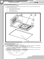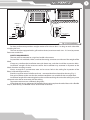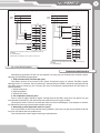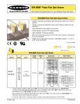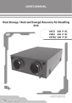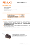
1
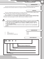
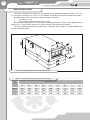
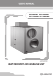
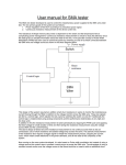
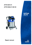
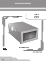
OPERATION MANUAL
PА 01 Е
PА 02 Е
PА 03 Е
Air Supply Unit
2
PА Е
CONTENTS
Introduction
Purpose
Delivery Set
Designation key
Basic technical data
Safety Requirements
Design and Operating Principle
Installation and Setup
Power Mains Connection
Technical Maintenance
Troubleshooting
Storage and Transportation Rules
Manufacturer’s Warranty
Acceptance Certificate
Connection Certificate
Warranty Card
3
3
3
3
4
5
6
6
8
9
10
10
11
12
12
12
3
INTRODUCTION
The present Operation Manual consisting of technical details, operating instructions and technical
specification for the installation of the PA E air supply unit of VENTS series (hereinafter Unit).
PURPOSE
The unit is designed to supply heated air in air supply systems of private residences, offices, hotels,
cafes, conference halls and other accommodation and public spaces.
PA E is a component unit and is not designed for autonomous operation.
The transported air must not contain any combustible or explosive mixtures, chemical fumes,
coarse dust, soot, fat or any environment prolific for the formation of harmful substances (toxic
substances, dust and pathogens) as well as sticky substances and fibrous materials.
The unit is not intended for operation by children or any persons with reduced
physical, mental or sensory capacities as well persons lacking the required training.
The unit must be handled only by properly qualified personnel after the
appropriate safety briefing
The installation are of the unit must be chosen to prevent access by unattended
children.
DELIOVERY SET
Unit Operation Manual
Delivery Packing: wooden box
- 1 piec;
- 1 piec;
- 1 piec.
DESIGNATION KEY
PА ХХ
Е
3
Number of power voltage phases
Heater Type
Е - electric heater
Capacity, m3/h
01, 02, 03
Unit Type
PA - air supply unit
4
PА Е
BASIC TECHNICAL DATA
The unit is designed for operation in an enclosed area at ambient temperatures from -25 ºC to +
55 ºC for PA 01 Е and from -25 ºC to + 45 ºC for PA 02 Е and PA 03 Е at relative humidity of up to 80%.
Hazardous parts access and water ingress protection standard:
unit motors - IP 44;
unit assembly connected to air ducts - IP 22.
The unit series designations, outside and connecting connections as well and its appearance are
given on Fig .1 and in Table 1 whereas the Table 2 contains the technical parameters.
The units undergo continuous improvements - therefore, some models may slightly differ from
the ones described herein.
Fig. 1. Outside and Connection Dimensions of Unit
Table. 1. Outside and Connecting Dimensions of Unit
Dimensions, mm
Type
B
B1
B2
B3
H
H1
H2
L
L1
PA 01 Е
400
420
624
582
200
220
374
1145
1106
PА 02 Е
500
520
689
646
300
320
447
1250
1212
PА 03 Е
600
620
888
744
350
370
500
1252
1212
5
Table. 2 . Unit Technical Parameters
Model
PА 01 Е
Supply Voltage, V/50 Hz
PА 02 Е
PА 03 Е
3 ~ 400
Maximum Fan Power, W
320
620
1330
Fan Current, A
0,55
1,05
2,4
Electric Heater Power, kW
12,0
18,0
21,0
Electric Heater Current, A
17,4
26,0
30,0
Total Unit Power, kW
12,4
19,0
22,4
Maximum Unit Current, A
18,0
27,1
32,4
Maximum Air Flow, m3/h
1275
2500
3350
Rotation speed, min-1
2700
2690
2730
Sound Pressure Level at 3m. , dB(A)
51
54
57
Maximum Transported Air Temperature, °C at T
from -25 to + 55
from -25 to + 45
Casing Material
Aluzinc
Insulation
50 mm, mineral wool
Filter
Panel type G4
Connected duct size, mm
400х200
500х300
600х350
Weight, kg
56
61
91
SAFETY REQUIREMENTS
While operating and mounting the unit consider the requirements of the present operation manual
as well as general requirements of all applicable local and national building and electrical codes and
standards.
The unit must be properly earthed!
Before connecting the unit to power mains make sure that the unit is free of any visible damages or
any other foreign objects inside the casing that can damage the impeller blades. Otherwise contact the
service center.
Warning!
Disconnect the unit from power supply prior to any mounting, servicing, connection
or repair operations with the unit.
•
•
•
Do not!
Do not operate the unit beyond the specified temperature range or in an aggressive
and explosive medium!
Do not connect clothes dryers or similar equipment to the ventilation system!
Do not operate the unit in the air and dust mixture medium!
6
PА Е
DESIGN AND OPERATING PRINCIPLE
The unit is designed for supply of purified and heated intake air. The unit design is given on Fig. 2.
The basic configuration includes:
Electric motor with a fan (Item 1).
Built-in electric heater (Item 2).
Class G4 filter (Item 3).
Detachable cover (Item 4).
2
1
3
4
Fig. 2. Unit Assembly and Operating Principle
INSTALLATION AND SETUP
The unit installation must ensure sufficient access for maintenance, servicing or replacement
operations. The arrow on cover must match the air flow direction in the system.
The unit is suspended on a rod threaded into an expansion anchor or, alternatively, securely fixed
in a horizontal position (Fig. 3).
The unit is integrated into a ventilation system by connection to rectangular or round air ducts
with the appropriate fittings (not included in the basic package).
7
Example 1
Spacer
Nut
Nut
Spacer
Rubber Vibration
Damper
Example 2
Nut
Spacer
Rubber Vibration
Damper
Nut with
Locknut
Fig. 3. Unit Installation
For best performance provide a straight section of air duct at least 1 m long on each side while
installing the unit.
The unit must be equipped with a grill or other device (maximum mesh size - 12.5 mm) to prevent
free access to the fans.
SAFETY REQUIREMENTS
The unit must be mounted on a rigid and stable substructure.
Suspend the unit with bolts. Make sure that the mating structure can withstand the weight of the
block.
If necessary, reinforce the installation area with beams etc., and then install the suspension bolts.
Insufficient strength of the structure used for the installation may resonate in response to the
block vibrations resulting in noise.
Always arrange for a maintenance zone and an access hole in the ceiling for inspection of the
filters, heat exchanger and fans.
Provide a separate access hole for each unit - see more details on the outline drawing (Fig. 1).
Prior to installation make sure that the ambient conditions are suitable for the unit operation.
Insufficient length of the mounting bolts to be used for attaching the unit to the ceiling may cause
abnormal noise due to resonance with the ceiling.
To prevent resonance use sufficiently long bolts.
If the abnormal noise is generated at the coiled duct mating replace the coiled duct with a flexible
line, or, alternatively, use flexible inserts to eliminate resonance.
8
PА Е
POWER MAINS CONNECTION
Disconnect the unit from the power mains prior to any electrical work.
The power mains connection shall only be performed by professional electricians
qualified for unassisted operations with electrical installations up to 1000 V after careful
reading of the present operation manual.
The rated electrical parameters of the unit are given on the manufacturer’s label.
Any tampering with the internal connections is prohibited and will void the warranty.
The unit is designed for connection to 400 V / 50 Hz three-phase AC mains.
The connection is made using durable, insulated and heat-resistant conductors (cables and wires)
with the minimum section of 4 mm2.
However, the given section value is tentative.
The choice of the required wire section in each case shall be based on the wire type, its maximum
permissible heating temperature, its insulation, length and installation method.
Use only copper core wires.
The unit must be connected to the power mains via an automatic cutout switch built into
the stationary wiring with a magnetic breaker. The trip current shall slightly exceed the current
consumption (see Table 2).
The fan electric motor connections shall be made on terminal block X1 mounted inside the
terminal box on the unit side wall in accordance with the electrical wiring diagram and terminal
designations.
Fig. 4 shows the fan motor connection diagram for three-phase mains.
The terminal designation diagram is glued on the inside of the terminal box.
The cables are routed into terminal box on the unit side wall through a sealed lead-in on the box
wall to ensure protection class compliance.
The external lead-in (400V/50Hz) must be equipped with an automatic cutout switch with a
magnetic breaker built into the stationary wiring to disconnect all the mains phases.
The position of QF external switch must ensure free access for quick power-off.
The electric heater power (contacts L1, L2 and L3) is supplied autonomously to terminal block X2
on the heater side wall according to the electrical wiring diagram (Fig. 4).
The same block terminates the normally closed contacts of thermal switches (TS1 and TS2 — from
the automatic reset thermal switch; TS3 and TS4 — from the emergency thermal switch with manual
reset) which commutate the electric heater power circuits depending on the customer’s needs.
If the product is equipped with a complete automatic control system the internal
electrical connections and the external connections must be made in accordance with
«Automatic Control System of Air Supply Unit with Electric Air Heater» operation manual
(included in the delivery package).
9
b) Electric Heater Power Wiring Diagram
a) Unit Fan Electric Motor Wiring Diagram
~400 V
50 Hz
L1
L1
L2
~400 V L2
50 Hz L3
PE
L3
PE
X1
1
W2
2
V2
3
U2
L1
4
U1
L2
5
V1
L3
6
W1
QF
L1
L2
L3
QF2
X2
L1
2
L2
L3
TB1
TB2
TB1
9
TB1
TB2
10
TB2
where QF is the automatic switch (not included in the delivery
package);
X1 - terminal block;
TB1 and TB2 - thermal protection contacts of the motor.
5
6
N
PE
3
4
7
8
1
7
8
TS1/1
TS1/2
1
1
2
2
TS2/1
3
3
TS2/2
4
4
where QF2 is the automatic switch (not included in the delivery
package);
X2 - terminal block;
Fig. 4. Unit Wiring Diagram
TECHNICAL MAINTENANCE
Maintenance operations of the unit are required 3-4 times per year. Maintenance includes regular
cleaning and the following operations:
1. Filter maintenance (3-4 times per year).
Dirty filters increase air resistance in the system and reduce supply air volume. The filters require
cleaning once in 3-4 months. Vacuum cleaning is allowed. Worn out filters should be replaced with the
new filters once or twice per year. Contact your local manufacturer representative for new filters. To
replace the filter:
1. Remove the cover.
2. Replace the filter.
3. Reinstall the cover.
2. Fan inspection (once per year).
Even in case of regular perform regular maintenance of the filter, some dust and grease can get
accumulated inside the fan and reduce the unit performance and supply air flow.
Clean the fan with a soft brush or cloth. No water and abrasive detergent, sharp objects or solvents
are allowed for cleaning to prevent the impeller damage.
3. Ductwork system inspection (once in 5 years).
Even if you follow all the listed maintenance guidelines, some dust can get accumulated inside the
air ducts and reduce the unit performance.
Duct maintenance means regular cleaning or replacements.
10
PА Е
TROUBLESHOOTING
Possible faults and fault handling
Trouble
Possible reasons
The fan does not
No power supply.
get started.
Cold supply air.
Low air flow.
Noise, vibration.
Fault handling
Make sure the power supply line is
connected correct, otherwise troubleshoot
the connection error.
Filter is clogged.
Clean or replace the filter.
Filter or fan is clogged.
Clean or replace the filter; clean the fan.
Ventilation system is clogged or
damaged.
Fan impeller is clogged.
The fan screws are loose.
Check the grille and clean it if required.
Make sure that the air ducts are not soiled
and not damaged.
Clean the fan impeller.
Check the screw tightening.
STORAGE AND TRANSPORTATION RULES
Store the unit in the manufacturer’s original packing box in a closed ventilated premise with
temperature range from +10°C to +40°C and relative humidity less than 80% (at +20°C).
Vapors or particles which can cause corrosion or damage the insulation or connection tightness
are not allowed in the storage environment.
Use hoist machinery for handling and transportation to prevent possible mechanical damages
of the unit.
Fulfill the requirements for transportation of the specified cargo type during cargo-handling
operations.
Use any vehicle types for the unit transportation provided that it is protected against mechanical
or weather damage.
Avoid any mechanical shocks and strokes during handling operations.
11
MANUFACTURER’S WARRANTY
Manufacturer hereby guarantees normal performance of the unit during two years from the date of
retail sale provided compliance with transport, storage, mounting and operation regulations.
In case of no confirmation of the sales date the warranty period is calculated from the manufacturing
date.
In case of failures in the unit operation during the warranty period the manufacturer will accept
reclamations and complaints from the owner of the device only after receiving technically sound act
with detailed description of the failure.
Unit damage as a result of unauthorized tampering with the circuit diagram is not a warranty case.
For warranty and post-warranty services of the unit please contact the product manufacturer.
In case of warranty claim please submit the present user’s manual with the seller’s stamp, filled
connection certificate and warranty card.
Warranty repair services and post-warranty services are fulfilled at the manufacturing facility.
WARRANTY CLAIMS ARE ACCEPTED WITH THIS USER’S MANUAL AND FILLED
CONNECTION CERTIFICATE ONLY.
The MANUFACTURER is not responsible for any mechanical or physical damages
resulting from the manual requirements violence, the unit misuse or gross mechanical
effect.
Fulfill the requirements set in the user’s manual to ensure proper functioning of the
unit.
12
PА Е
ACCEPTANCE CERTIFICATE
The air handling unit with heat recovery PA E
has been duly certified as serviceable.
Acceptance Inspector’s Stamp
Date of manufacture _____________________
Sold by
Name of trade company _______________________________________________________________
___________________________________________________________________________________
Date of sale _____________________________
ELECTRICAL CONNECTION CERTIFICATE
This is to certify that the air handling unit PA E has been connected to power mains pursuant to
the requirements stated in the present user’s manual by a qualified technician:
Company:
Name:
Date:
Signature
WARRANTY CARD
V53ENG-02