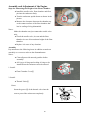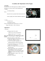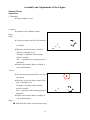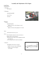
1
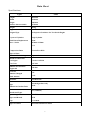
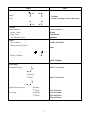
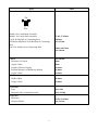
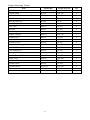
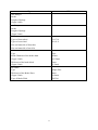
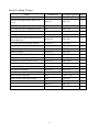
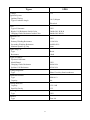
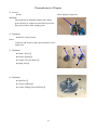
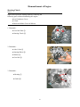
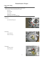
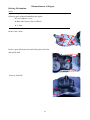
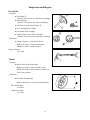
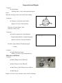
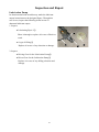
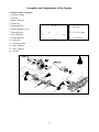
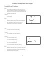
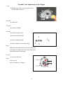
Brief Introduction Notices This User Manual, compiled by ACCESS MOTOR, is especially for the distributors and service personnel of ACCESS MOTOR. Impossibility of covering all knowledge related to ATV defines the User Manual to be used by the mechanic, who can further develop a good sense of theory of engine, procedure of maintenance, and skills of maintenance, in only maintaining and repairing ACCESS MOTOR ATV. In the event of lacking such know-how, either inappropriate fitting or danger upon assembly, in the process of repairing ATV, will occur. ACCESS MOTOR will try hart to improve all types and inform the distributors in advance in case of any modification or alteration of the specifications and make it incorporated into the revised User Manual. It is important to notice. The following three words always appear in the Manual and are outlined below: WARNINGS: it indicates some procedures must be abide by; otherwise may cause damages to the operator, other persons or vehicles and even cause death. NOTICES: it indicates some procedures must be abided by, so as to avoid damages upon vehicles. NOTE: it indicates some procedures are detailed in the note. 1 1. Identification of the ATV Body and Engine 1.1 Stenciling Position of VIN Number 2nd European Code 50CC:RK3SP10037A000001 1.2 Stenciling Position of Engine Number 50CC:E03R000001 2 2. Important Notes A. Preparations 1. Assuredly clear up dirt and dust on the engine of automobile to avoid it to be interfused in the engine or other parts. 2. Special tools, appropriate instrument, and correct operation should be applied to special places in efforts not to damage the special parts, e.g. double open-box wrench set and socket wrench shall be used instead of spanner. 3. It is noticeable for dismantlement and assembly. Measure and record the dismantlement as reference for the assembly. Keep the dismantled parts by classification in order to avoid mixing and loss. Clean the engine, gears and other parts with kerosene and diesel oil and have them dried with air after being dismantled. Compare the repaired and maintained parts to that before being dismantled and then assemble them. Parts for assembly must be kept from any foreign matter. All bumpers must be operated before assembly. All movable parts must be supplied with lubricants or greases. Lock screws with the designed torque. Closely coordinate with each other in order to avoid loss or disoperation. 4. No fire is permitted during the maintenance and in the maintenance place. B. Gasket, Oil Seal and O-typed Oil Ring 1. Gaskets, asbestos gaskets, oil rings, bolts and small clips shall not be reused after being dismantled. C. Special Tools Special tools shall be applied to special places in efforts not to damage the special parts during dismantlement and assembly. Adjustment and Measurement 1. Engine Speed Meter: to test the engine speed 2. Gage: To measure the gasoline level of the floating chamber 3 3.Torque Wrench: To lock screw caps and bolts and measure the torque 4. Avometer: To test the voltage, current and resistance 5. Vernier Scale: To measure the depth, inside diameter and diameter etc. 6. High Voltage Coil Meter: To detect the gap of the spark plug. Engine 1. Crankcase Tools To dismantle the crank shaft and the crank case. 4 2. Rotating Part Fixer To unfasten and fasten the screw caps and fix the clutch assembly and generator. 3. Generator Flyer Drawer To dismantle the generator. 4. Clutch Twister To remove the clutch springs. 1 2 5. Oil Seal Assembly Tools Oil Seal Leading Tools Oil Seal Assembly Tools To be used to assemble the oil seal of the crank shaft 6. Oil Seal Leading Tools To be used to assemble the oil seal of the clutch 5 7. Clutch Cover Scotch To fix the clutch disk 8. Wrench To fasten or unfasten the caps on the clutch 1 3 2 9. Crank Assembly Tools Crank Assembly Tube Crank Assembly Bolt Crank Assembly Connecting Tube To be used to assemble the crank shaft and the crankcase 10. Shock Eliminator Adjustable Wrench To adjust the shock eliminator’s springs 11. Tyre Pressure Gauge To be used to detect the tyre pressure 6 Data Sheet Specifications: SP50 Types Length 1825 mm Width 1230 mm Height 1140 mm Distance between shafts 1270 mm Weight 181 kg Engine Original Type Air-Injection Crankcase for Two-Stroke Engine Layout of Cylinders Single Cylinder Total Piston Displacement 49cm³ Bore * Stroke 40.0mm*39.2mm 9.5:1 Compression Ratio Electric/Foot Kick Types of Start Method of Lubricating Separate Lubrication Brands of Lubricants For Engine 2 Stroke SAE #20 For Gears SAE #40 Amount of Lubricants Engine Oil Gear Oil Amount Changed Total Amount Air Filter Fuel Type Amount in Gasoline Tank Carburetor Brands and Types 110±10cc 0.2L 0.22L Wet Materials unleaded gasoline Only 14.8L TK (VM16SS) Spark Plug BPR7HS Types and Brands NGK Gap 0.9~1.0mm Types of Clutch Dried Inward Direct-Loaded 7 Types SP50 Cylinder Head: Torque Limit: 0.03mm * Check according to the six directions Cylinder Inside Diameter: (Upper Limit) Taper Limit Out of Round Limit (39.993~40.012mm) 0.1mm 0.05/100mm 0.006mm Piston: Size of Piston: 39.958~39.972mm Measurement Position*: 5mm Piston Clearance: 0.035~0.040mm Piston Ring: Sectional Drawing: BxT=1.2x1.6(mm) B Top Ring: 2nd Ring: BxT=1.2x1.6(mm) B Depth of Ring Groove: Close Gap: Top Ring : 2nd Ring: Top Ring: 0.15~0.35(mm) 0.15~0.35(mm) 0.03~0.05(mm) 0.03~0.05(mm) nd 2 Ring: 8 Types SP50 Crank Shaft: F C C D A Width A for Crank Shaft Assembly: Width C for Crank Shaft Assembly: Gap D for Big End of Connecting Rod: Oscillation Amplitude E for Bid End of Connecting Rod: Gap F for Small End of Connecting Rod: Clutch Thickness of Clutch (Upper Limit) Length of Pressure Spring External Diameter of Balancing Weight 37.90~37.95mm 0.03mm 0.2~0.5mm 0.004~0.017mm 0.4~0.8mm 0.4~0.8mm 2mm 1mm 29.9mm 15.0mm 14.5mm (Upper Limit) V-Belt Width of Belt (Upper Limit) 16.6mm 14.6mm Foot Pedal Type Designed Value of Spring Pressure Gear Idle 0.15~0.25Kg Leaf Valve Thickness Obstruct Height 0.150~0.154mm 6.0~6.4mm 9 Engine Fastening Torque Item Thread Dia Torque (Kg-cm) Qty Spark Plug M14x1.25 150~250 1 Cylinder Head M7x1.0 130~150 4 Double-Headed Bolts for Cylinder M7x1.0 140~200 4 Bolts for Water Pump Cover M6x1.0 70~100 2 Bolts for Dust Cap M5x0.8 30~50 2 Lubricating Pump M5x0.8 30~50 2 Leaf Valve M6x1.0 70~100 4 Air Filter M6x1.0 70~100 2 Exhaust Pipe M6x1.0 70~100 2 Exhaust Tailpipe M8x1.25 120~150 1 Crankcase R, L M6x1.0 70~100 6 Crankcase Cover M6x1.0 70~100 8 Gear Box Cover M6x1.0 70~100 6 Bolts for Discharging Oil M8x1.25 70~100 1 Gear Idle Plate M6x1.0 70~100 2 Foot Starting Rod M6x1.0 70~100 1 Starting Motor M6x1.0 70~100 2 Counter Grooved Wheel Assembly M28x1.0 450~550 1 Clutch Cover M6x1.0 100~160 1 One Way Clutch M10x1.25 250~350 1 Generator Seat M6x1.0 70~100 1 Generator Rotor M10x1.25 250~350 1 Drive Sprocket M14x1.5 300~400 1 10 Types SP50 Front Damper Stroke Length of Springs (Upper Limit) Rear Damper Stroke Length of Springs (Upper Limit) Wheel Types of front wheel Types of rear wheel Size and materials of front disc Size and materials of rear disc 21x7-10 20x11-9 Brake Type Inside Diameter of the brake drum (Upper Limit) Thickness of the brake block (Upper Limit) Disc 85mm (85.5mm) 3mm (1.5mm) Rear Brake Type Thickness of the Brake Sheet (Upper Limit) Single Disc 4mm (0.8mm) Type of Brake Fluid DOT#4 11 Body Locking Torque Item Thread Dia. Torque (Kg-cm) Qty Bolts for Holders above Handles M8 150~250 2 Nuts for Steering Linkage Axle Seat Cover M8x1.25 200~300 4 Nuts for Steering Linkage M8x1.25 200~300 2 Self-Lock Nuts for Front Brake Drum M12 650~700 1 Fixing Nuts for Front Disc M14 900~1000 2 Fixing Nuts for A Arm M10 450~600 8 M10x1.25 450~600 4 Self-Lock Nuts for Steering System M10x1.25 450~600 4 Bolts for Gasoline Pipe M10 450~600 4 Bolts for Engine Fixer M8 200~300 6 Bolts for Engine M10x1.25 450~600 2 Bolts for Rear Damper Cover M12x1.25 650~700 1 Bolts for Rear Stirrup M8x1.25 200~300 2 Fixing Bolts for Rear Wheel Axle M14x1.25 900~1000 1 Bolts for Rear Brake Caliper M12x1.25 650~700 4 Bolts for Holders of Rear Brake Disc M8x1.25 200~300 2 Rear Shock Eliminator M10x1.25 450~600 4 Self-Lock Nuts for Rear Disc Holder M10x1.25 450~600 2 Rear Nuts for Front Disc M18 1200~1350 2 Bolts for Rear Chain Wheel Base M10 450~600 8 Bolts for Gasoline Tank M10 450~600 4 M8x1.25 200~300 5 M6x1.0 75~120 2 Upper and Lower Bolts and Nuts for Front Shock Eliminator 12 Types SP50 Voltage Ignition System Ignition Timing Type of Advance Angle 12V 18∘/5,000rpm Electrical CDI Type of Generator Ripple Coil Resistance Inside/Color Charging Choke Resistance Inside/Color 3XG 500Ω±20% W/R-B 800Ω±20% B/R-B Ignition Coil Type Primary Winding Resistance Secondary Winding Resistance Minimal Spark-Lug Gap 3XG 1.1Ω±20% 6.6KΩ±20% 6mm Spark Plug Lid Type Resistance Resin 10kΩ Types of Charge Flywheel Generator Model/Brand Charging Choke Resistance Ignition Coil Resistance 3XG 0.6Ω±20% 0.5Ω±20% Voltage Regulator Type Short Circuit by Semiconductors Selenium Rectifier Type Capacity SH614-12 8A Storage Batteries Capacity Specific Gravity 12V 5AH 1.32 Starting Motor Type 3XG Breaker Type Fuse 4A 13 Total Torque Specification (Standard Bolt) This table is conformable to the Bolt Locking Specifications released by the International Standard Association. Lock bolts across or subject to the designed order in order to avoid any torsion or unbalance. ※ Use a torque wrench to test the torque ※1kgf.cm=0.098066N.m Total Torque A B 10mm 6mm 60 12mm 8mm 150 14mm 10mm 300 17mm 12mm 550 19mm 14mm 850 22mm 16mm 1300 Kg/cm A: Through Space B: External Diameter of Screw Thread A B 14 Inspection & Adjustment Section The maintenance intervals in the follow table are based upon average riding and condition. Riding in usually dusty areas requires more frequent servicing. Periodic Maintenance/Lubricating Table First 200km and 30-hour’s Riding Every 100 hours Every 200 hours Every 300 hours Engine Oil I I I I Gear Box Oil R Items R Air Filter C Fuel Filter R R Oil Filter R Spark Plug I Carburetor I I I Engine Idle I I I I Throttle Valve Operation I Fuel Pipe I Turning of Front Arm A L Steering Linkage Operation I Brake Gasket I Driving System I Suspension System I Batteries I DRIVE BATTERY I Wheel Bearing I Chains A Throttle Cable I Cooling Water in Water Tank Inspect and add every day before riding Brake System Inspect every day before riding Type Pressure Inspect and add every day before riding NUTS/BOLTS/FASTENERS A: Adjust T C: Clean I: Inspection R: Replace T: Tighten L: Lubricate 15 Dismantlement of Engine Notes: The engine shall not be dismantled in case of removal of the following parts: ● Main and Counter Grooved Wheel ● Carburetor ● CDI Generator ● Starting Motor ● Lubrication Pump ● Cylinder Head ● Cylinder ● Piston Cushion, Covers, Storage Batteries, Boxes and Foot Pedal 1. Dismantle: ● Cushion ● Covers ● Storage Batteries Carburetor 1. Dismantle: ● Ventilating Tube (beside the carburetor) ● Air Filter ① ① 2. Dismantle: ② ● Lubricating Pipe ① ① ● Carburetor Assembly ② 16 Dismantlement of Engine Pipes, Wire Ropes and Wires Uint 1. Dismantle: ● Lubricating Pipe ① ① (beside the lubricating box) ● High-Voltage Wires ② ② ● Power Line of Thermal Switch ③ ③ Notes: Clog the lubricating pipe ① and the openness of the lubricating box in order to prevent lubricants from flowing. 2. Dismantle: ② ● Cooling Water Pipes ① Connecting Water Tank to Engine ● Generator Housing ② ① 3. Dismantle: ● Lubrication Pump Housing ① ① 4. Dismantle: ● Lubrication Pump Wire Rope ① ① 17 Dismantlement of Engine 5. Dismantle: ① ● CDI Generator Wires Unit① ● Starting Motor Wires Unit② ② ① 6. Dismantle: ● Fixing Screws of Exhaust Pipe ① ● Fixing Screws behind Exhaust Pipe ② Notes: Pay attention to the temperature of the exhaust pipe. ② 7. Dismantle: ● Engine ①② ① 18 ② Dismantlement of Engine Cylinder Head, Cylinder and Piston Notes: Inspect and repair the cylinder head, cylinder and piston by removing the following parts without dismantling the engine: ● Covers ● Food Pedal ● Carburetor 1. Dismantle: ● Engine Mount ① ① 2. Dismantle: ● Intake Manifold ① ● Leaf Valve ● Gaskets ① 3. Dismantle: ② ● Spark Plug ① ① ● Cylinder Head ② ● Gaskets Notes: ● Loosen the nuts across ● Loosen each nut by ¼ circle and take down after loosing all nuts. 19 Dismantlement of Engine 4. Dismantle: ① ● Cylinder ① ● Gaskets of Cylinder ② ② 5. Dismantle: ● Grip Ring for Piston Pin ① ① Notes: Clog the opening of the crankcase with dried textile to prevent the grip ring ① from slipping into the case. 6. Dismantle: ● Piston Pin ① ● Piston ② ● Bearings on Small End Notes: ② Remove the collected carbons from the grip ring groove and the pin hole before dismantling the piston pin to make the operation easy. Notes: A hammer is prohibited for dismantlement of the piston pin. 20 ① Dismantlement of Engine Foot Shaft, Main and Counter Grooved Wheel and V-Belt Notes: Inspect and repair the foot shaft, main and counter grooved wheel and V-belt without dismantling the engine and any part. 1. Discharge the gear oil. 2. Dismantle: ① ② ● Foot Lever ① ● Crankcase Cover (Left) ② ● Anchor Pin 3. Dismantle: ● Foot Small Gears ① ● Clamp ② ③ ① ② 4. Take down: ● Extension Springs ③ 5. Dismantle: ● Grip Ring ① ② ① ● Plain Washer ② ● Sleeves ③ ● Foot Shaft Assembly ④ ● Plain Washer ⑤ ③ ⑤ ④ 6. Dismantle: ● O-Type Oil Ring ① ● Nuts for Clutch Hub ② Notes: ② Use Pneumatic tools to dismantle. 21 ① 22 Dismantlement of Engine 7. Dismantle: ● Counter Grooved Wheel Assembly ① ● V-Belt ② ● Gaskets ③ Notes: As shown in the picture, push with hands the counter grooved wheel assembly to remove the wheel assembly and the V-belt together. ③ ② ① 8. Dismantle: ● Nuts for Main Grooved Wheel ① Notes: Use Pneumatic tools to dismantle. ① 9. Dismantle: ● Fastigiate Spring Gasket ① ● One Way Clutch ② ● Gasket ③ ● Main Fixing Grooved Wheel ④ ● Plain Washer ⑤ ② 10. Dismantle: ● Axle Collar ● Main Sliding Grooved Wheel Notes: Hold the cam and grooved wheel together to prevent the counter-weight balls from dropping. 23 ① Dismantlement of Engine 11. Loosen: ● Nuts Warnings: Nuts shall not be dismantled unless the counter grooved wheel is compressed and fixed to prevent the grooved wheel from springing out. Clutch Spring Compressor 12. Dismantle: Lock Nut Wrenchr ● Nuts for Clutch Carrier Notes: Compress and fix the counter grooved wheel with a torque tool. ① ③ ② 13. Dismantle: ● Clutch Carrier ① ● Pressure Spring ② ● Counter Grooved Wheel ③ ● Spring Seat ④ ④ 14. Dismantle: ② ● Guide Pin ① ● ① ● O-Type Oil Ring ② ● Counter Sliding Grooved Wheel ③ ③ 24 ① Dismantlement of Engine Starting Clutch Notes: Inspect and repair the starting clutch by removing the following parts without dismantling the engine: ● Left Crankcase Cover ● V-Belt ● Main and Minor Grooved Wheels ① 1. Dismantle: ● Gear Idle Plate ① ● Starting Clutch ② ② ② ① 2. Dismantle: ● Axle Collar ① ③ ● Starting Wheel ② ● Washer ③ ● Gear Idle ④ ④ 3. Dismantle: ② ● Bearing ① ● Gasket ② ① 25 Dismantlement of Engine CDI Generator Notes: Inspect and repair the CDI generator by removing the following parts without dismantling the engine: ● Covers ● Foot Pedal ● Inlet eye of Cylinder 1. Dismantle: ● Nuts for Rotor ① ① ● Plain Washer Notes: Use Pneumatic tools to dismantle. 2. Dismantle: ● Rotor ① ① Notes: Remove the rotor with a flywheel drawer ② ② ③ 3. Dismantle: ① ● Armature Assembly ① ② ● Semi-Round Key ② ● Gasket ③ 26 Dismantlement of Engine Lubrication Pump Notes: Inspect and repair the lubrication pump by removing the following parts without dismantling the engine: ● Covers ● Foot Pedal ● Air Filter ● Inlet Eye of Cylinder ● Wire Rope of Lubrication Pump 1. Dismantle: ● Lubrication Pump ① ① 2. Dismantle: ● Clip Link ① ② ● Drive Gear ② ① 3. Dismantle: ● Anchor Pin ① ① ● Clip Link ② ② 27 Dismantlement of Engine Driving Mechanism Notes: Inspect and repair the driving mechanism by removing the following parts without dismantling the engine: ● Left Crankcase Cover ● Main and Counter Grooved Wheel ● V-Belt Remove the 9 bolts. Bolts Remove gear shift drum.Gear shift fork guide shaft.Gear shift guide shaft. Gear Shift Guide Shaft Gear Shift Drum Gear Shift Fork Guide Shaft Remove shift fork. Shift ,Fork 28 Dismantlement of Engine Remove washer plate、main axle comp、main axle. Washer , Plate Main Axle Main Axle Comp Remove drive gear primary. Drive Gear, Primary Check all the bearing are normal, if not, change to new parts Bearing Bearings Bearing 29 Dismantlement of Engine Check all the gear operation are normal, if not, change to the new parts. Install the brake pad as the reverse process. NOTS: Install gear shift fork guide shaft、gear shift drum need to line up to the 3rd tooth of the gear 30 Dismantlement of Engine Starting Motor Notes: Inspect and repair the starting motor by removing the following parts without dismantling the engine: ● Exhaust Pipe Assembly ● Rear Wheel 1. Dismantle: ① ● Starting Motor① Crankcase (Right) 1. Dismantle: ● Screws M6x35 ● Oil Seal Blocking Sheet ① ② ① 2. Dismantle: ● Crankcase (Right) ② Notes: Loosen each nut by ¼ circle and take down after loosing all nuts. ③ Process of Crankcase Dismantlement: ● Install crankcase dismantlement tools ③ Notes: Lock the screws of the tool and make it paralleled to the crankcase. Loosen slightly one fixing screw when necessary in order to adjust the tool to parallel. 31 Dismantlement of Engine ● Constantly tap each installation base of the engine in turn during dismantlement operation and then remove the right crankcase. ● Tap each strengthening part of the crankcase with a plastic hammer. ● Don’t tap the gasket of the crankcase. ● Pay attention to the dismantlement. ● Remove the right as well as the left crankcases completely. Take down the dismantlement tool and reinstall it if the right or the left crankcase doesn’t have been removed completely. Don’t dismantle the crankcases by force but check if screws haven’t been unfastened. 3. Dismantle: ② ● Crank Shaft ① ① Notes: ● Remove the crank shaft with the crankcase dismantlement tool②. ● Lock the screws of the tool and make it paralleled to the crankcase. Loosen slightly one fixing screw when necessary in order to adjust the tool to parallel. 32 Inspection and Repair Cylinder Head 1. Remove: ● Collected carbon from the combustion chamber with a scraper① Notes: Don’t use pointed tools in order to prevent the spark plug installation teeth from being damaged or scratched. 2. Inspect: ● Cylinder Head Replace it in case of any scratch or damage 3. Measure: ● Warpage Adjust it in case of any inconformity Warpage Limit: 0.03mm ************************************ Measuring Steps: ● Put an angle square① on the cylinder head and measure the Warpage with a thickness gauge②. ● Adjust the cylinder head in case of inappropriate Warpage. ************************************* 4. Finish ● Cylinder Head ************************************* Repair Steps: Put a sand paper #400~600 on a flat face and finish the cylinder head on it at an order like 8. Notes: Rotate the cylinder head to finish it in order to avoid much abrasion of one edge of the cylinder head. ************************************* 33 ① Inspection and Repair Cylinder and Piston 1. Remove: ● Collected carbon with round-headed scrapper Notes: Don’t use pointed tools in order to prevent damage or scratch. 2. Inspect: ● Cylinder Wall Hone or replace it in case of any abrasion or scratch. 3. Remove: ● Collected carbon from the piston crown and the ring grooves. ● Piston Crown Replace it in case of any scratch or damage. 5. Remove: ● scratch or collected carbon from the piston walls with sand paper #600~800 Notes: Remove it across and avoid over attrition. 6. Inspect: ● Piston Walls Replace it in case of any abrasion, scratch or damage. 34 Inspection and Repair 7. Measure: ● Clearance between piston and cylinder **************************************** Measuring Steps: Step 1: ● Measure the C value of the cylinder with a cylinder gauge. Notes: Parallel the cylinder gauge to the crank shaft at a right angle and then measure the average value. Reference Value Wear Limit C Value of Cylinder 53.993~54.112mm 54.93~54.012mm 51.993~52.112mm 52.93~52.012mm 49.993~50.112mm 50.93~50.012mm 39.993~40.112mm 40.93~40.012mm Taper (T) ----- 0.05mm Out-of Round (R) ----- 0.006mm If C=D, the max.: T: (max. of D1 or D2)―(max. of D5 or D6) R: (max. of D1, D3 or D5)- (max. of D2, D4 or D6) ● Hone or replace the cylinder, the piston and the piston ring in case of any inconformity. Step 2: ● Measure the P value of the skirt section of the piston with a micrometer caliper. ⓐ5mm shall be started from the bottom of the piston. Piston Size “P”: Standard Size: 53.958~53.972mm 51.958~51.972mm 49.958~49.972mm 39.958~39.972mm 35 ⓐ ● Replace the piston and the piston ring in case of any inconformity. 36 Inspection and Repair Steps 3: ● Calculate the clearance between piston and cylinder according to the following formula: Clearance to Cylinder: C value of Piston to Cylinder P value of skirt section of the clutch ● Hone or replace the cylinder, the piston and the piston ring in case of any inconformity. Clearance between Piston and Cylinder: 0.035~0.040mm Upper Limit: 0.1mm ************************************* Piston Ring 1. Measure: ● Side Clearance Replace the piston in case of any inconformity or/and measure it with a thickness gauge①. Side Clearance: Top Ring: 0.03~0.05mm 2nd Ring: 0.03~0.05mm 2. Install: ● Piston into the cylinder Notes: Put the piston ring into the cylinder and press it down with the piston crown in order to make it vertical to the cylinder walls. 3. Measure: ● Tip Clearance Replace it in case of any inconformity Measure it with a thickness gauge①. Tip Clearance: Top Ring: 0.15~0.35mm 2nd Ring: 0.15~0.35mm 37 Inspection and Repair Piston Pin and Bearing 1. Inspect: ● Piston Pin Replace it in case of any burn or scratch and examine the lubricating system. ⓐ 2. Measure: ● External Diameter of the Piston Pinⓐ Replace it in case of any inconformity. ED (Piston Pin)ⓐ: 9.996~10.000mm ⓑ 3. Measure: ● Clearance between Piston Pin and Piston. Replace it in case of any inconformity. Clearance between Piston Pin and Piston: 0.008~0.015mm 4. Inspect: ● Bearing of the Piston Pin Replace it in case of any deformation or damage. Leaf Valve 1. Inspect: ● Leaf Valve ① ● Leaf Valve Stopper ② Replace it in case of any crack or damage. 38 Inspection and Repair Foot Shaft 1. Inspect: ● Foot Shaft ① Replace it in case of any abrasion or damage. ● Return Spring Replace it in case of any crack or damage. ● Nail Groove (Foot Small Gear) ② ● Gear Teeth③of Foot Shaft ● Foot Small Gear Teeth④ ● Toothed Fact of One Way Clutch⑤ Replace it in case of any abrasion or damage. 2. Measure: ● Clamp Tension← (Foot Small Gear) Replace it in case of any inconformity. Measure it with a spring balancer. Clamp Tension: 150~250g Clutch 1. Inspect: ● Inside walls of the clutch hub Replace it in case of any scratch or rust. Polish the inside walls with emery clothes in case of any scratch. 2. Measure: ● ID of the clutch hubⓐ Replace the hub in case of any inconformity. ID (Clutch Hub): 112.0mm (Abrasion Limit): 112.3mm 39 ⓐ Inspection and Repair 3. Inspect: ● Clutch Block Polishing Parts→rub it with rough sand papers. Notes: Wipe the clutch up with a clean textile after rubbing. 4. Measure: ● Thickness of ⓐ of the clutch block Replace it in case of inconformity Thickness of Clutch Block: 2mm (Abrasion Limit): 1mm 5. Measure: ● Flexible Length of the Clutch Balance A Weight Spring (Balance Weight Spring)ⓐ Replace it in case of any inconformity. Flexible Length (Balance Weight Spring)ⓐ: 29.9mm 6. Inspect: ● Clutch Block Movement Replace it in case of any unsmooth ness. Main Grooved Wheel 1. Inspect: ● Main Sliding Grooved Wheel① ③ ① ● Main Fixing Grooved Wheel② ● Shaft Sleeves ③of Sliding Grooved Wheel ● Shaft Ring ④ Replace it in case of any abrasion, crack, scratch or damage. 40 ④ ② Inspection and Repair 2. Inspect: ● Free Movement Put the shaft ring①into the main sliding grooved wheel② to test the free movement. Replace the grooved wheel or the shaft ring in case of getting stuck or loosen. 3. Inspect: ● Ball Bearings Replace them in case of any damage 4. Inspect: ● ED of Ball Bearings Replace them in case of any inconformity. ED of Balance Weight : 15.0mm (Limit) :14.5mm A A: Worn Parts B: Measurement Points A 5. Inspect: ● Cam① of Main Grooved Wheel ● Sliding Fittings② ② Replace them in case of any abrasion or damage. ① 6. Inspect: ● Cam Movement Situation Repair in case of any unsmoothness. 41 Inspection and Repair V-Belt 1. Inspect: ● V-Belt Replace it in case of any crack, abrasion, off-line and gap. Replace it in case of any oil remains. 2. Measure: ● Width of V-Belt ⓐ Replace it in case of any inconformity. Width of V-Belt: 16.6mm (Limit): 14.6mm Notes: Measure each poison of the V-belt. a ⓐ Counter Grooved Wheel 1. Inspect: ● Counter Grooved Wheel (Fixed) ● Counter Grooved Wheel (Movable) ① ② ● Oil Seal② dd Replace the set in case of any scratch, crack or damage. dd ① 2. Inspect: ● Torque Guide Channel① dd ● Guide Pin② dd Replace the set in case of any abrasion or damage. dd 3. Inspect: ● Movement of the Sliding Grooved Wheel ① Replace the set in case of any unsmoothness. ③ dd ② dd dd 4. Measure: ● Spring Flexible Length (Counter Grooved Wheel) dd dd 42 dd Replace it in case of any inconformity. Flexible Length (Counter Grooved Wheel)ⓐ: 94.0mm (Limit): 91.0mm 43 Inspection and Repair Starting Clutch Gear 1. Inspect: ● Starting Clutch ① Insert the anchor pin①into the groove and turn it counterclockwise. Replace the starting clutch assembly in case of unsuccessful operation. 2. Inspect: ① ● Starting Gear Teeth① ● Gear Idle Teeth② Replace them in case of any burn, deformation, ② abrasion or gap. 3. Inspect: ● Contact Surface (Starting Wheel) ① ● Contact Surface (Bearing) ② ③ ② ① ● Gasket③ Replace them in case of any falling or damage. 4. Inspect: ● Operation of the Starting Clutch ********************************************** Steps: ● Install the starting wheel on the starting clutch and then make the clutch not to move. ● Turn the starting wheel counter clockwise to where marked A, and the wheel and the clutch get stuck. Their failure to get stuck indicates the clutch is damaged, so replace it. ● Turn the starting wheel clockwise to where marked B, and the wheel and the clutch can move individually. The failure indicates the clutch is damaged, so replace it. ********************************************** 44 B A Inspection and Repair Lubrication Pump Its abrasion and inside troubles may make the lubricant output inconsistent to the designed figure. Though this case is rare, inspect the following items in case of abnormal lubricant output. 1. Inspect: ● Lubricating Pipe1.2① ② Blow it through or replace it in case of block or crack. ● O-type Oil Ring② Replace it in case of any abrasion or damage. 2. Inspect: ● Driving Gear for the Lubrication Pump③ ● Driven Gear for the Lubrication Pump④ Replace it in case of any falling, abrasion and damage. 45 ① ④ ③ Inspection and Repair Crank Shaft 1. Measure: ● Out-Of-Round “C” ● Side Clearance “D” of the big end of the connecting rod ● Free clearance limit “F” of the small end of the connecting rod. Replace it in case of any inconformity. Measure the values above with V-type bearing seat, micrometer and thickness gauge. Limit of Out-of-Round “C”: 0.03mm Side Clearance “D”: 0.2~0.5mm Free clearance limit “F”: 0.4~0.8mm Crankcase 1. Clean the crankcases with neutral solvent. 2. Clean all contact surfaces on the crankcases, including the gasket contact surface and the surfaces of the right and left crankcases. 3. Inspect: ● Crankcase Replace it in case of any crack or damage. Bearing and Oil Seal 1. Inspect: ● Bearing for Engine Rotate the inside edge by hands after being cleaned and lubricated. Replace it in case of bad performance. 2. Inspect: ● Bearing for Engine Replace it in case of any abrasion or damage. 46 F c c Assembly and Adjustment of the Engine Crankcase and Crankshaft 1. Oil Seal Stopper 2. Oil Seal 3. Right Crankcase 4. Anchor in 5. Bearing6204C3 6. Engine Damper Cover 7. Starting Motor 8. Left Crankcase C:0.03mm D:00.2~0.5mm F:0.4~0.8mm 9. Needle Bearing 10. Crank Pin 11. Connecting Rod 12. Left Crankcase 13. Left Crankcase 14. Oil Seal 3 6 1 7 2 OIL 4 13 5 6 8 9 10 11 14 12 5 47 Assembly and Adjustment of the Engine Crankshaft and Crankcase Notes: Lay the lithium soap greases on the oil seal lip in order to make the installation of the crankshaft easy and prevent it from being scratched and lubricate the bearings with engine oils. 1. Install: ● Bearing① b Notes: Make the signed surfaceⓐ,ⓑof the bearing facing the crankshaft and give a pressure from the exposed part of the bearing to assemble it. 2. Lay: ● Engine oil on the crank bearing 3. Install: ● Crankshaft (to the left crankcase) 4. Install: ● Crank Assembly Tools 1 ● Crank Assembly Tube① ● Crank Assembly Bolt② 2 ● Crank Assembly Connecting Tube③ Notes: Make the connecting rod stay at the top stuck point and turn the assembly tool till the lower part of the crankshaft contacts the bearing. 48 3 Assembly and Adjustment of the Engine 5. Lay: ● Binding agent on the contact surface of the left and right crankcases. 6. Install: ● Anchor Pin 7. Install: ● Crankcase (Right) 8. Install: ● Crank Assembly Tools ●Crank Assembly Tube① 1 ●Crank Assembly Bolt② 2 ●Crank Assembly Connecting Tube③ Notes: Make the connecting rod stay at the top stuck point and turn the assembly tool till the lower part of the crankshaft contacts the bearing. 9. Lock: ● Screws(Crankcase) Notes: Lock it across. Screws(Crankcase): 90Kg/cm 49 3 Assembly and Adjustment of the Engine 10. Install: ● Oil Seal (Unused)① ② Into the Left Crankcase ① Notes: ● With a oil seal assemble tool② ● Smear the oil seal lip with lithium soap greases. Notes: An unused oil seal is required. 11. Install: ● Oil Seal (Unused)① Into the Left Crankcase Notes: Smear the oil seal lip with lithium soap greases. Notes: An unused oil seal is required. 12. Inspect: ● Operation of the crank shaft. Tap with a plastic hammer the crankcase till return to the original point. Notes: Do not knock the crack shaft. 13. Install: ● Oil Seal Stopper① Screws (Oil Seal Stopper): 90Kg/cm ① 50 Assembly and Adjustment of the Engine 14. Install: ● Starting Motor① ① Bolts (Starting Motor): 130Kg/cm 51 Assembly and Adjustment of the Engine Driving Mechanism 1. Bearing 2. Oil Seal 3. Oil Filter Plug 4. O-type Oil Ring 5. Copper Plain Washer 6. Bolt for Discharging Oil 7. Driven Shaft 8. Bearing 9. Gear Idle 10. Conical Spring Gasket 11. Oil Seal 12. External Clamp 13. Gear Box Cover 14. Gasket for Gear Box Cover 15. Anchor Pin 16. Bearing 17. Main Driving Gear 18. Gasket for Left Crankcase Cover 3 1 2 4 chang new parts OIL chang new parts 7 17 5 16 6 15 chang new parts 12 chang new parts 11 15 14 chang new parts 52 9 10 13 18 8 Assembly and Adjustment of the Engine Lubrication Pump and CDI Generator 1. Water Pump Assembly 11. Magneto Assembly 2. Bearing 12.A.C.G Gasket 3. Spacer Tube 13. Oil Pump Assembly 4. Anchor Pin 14. Anchor Pin 5. Pump Actuator Disc 15. External Clamp 6. External Clamp 16. Drive,Gear, Oil-Pump 7. Pump Actuator Bolt 8. Nut 9. Plain Washer 10. Fly Wheel 100kg/cm 7 8 9 10 1 2 11 3 2 chang new parts 15 4 16 15 5 380kg/cm 6 chang new parts 14 13 80kg/cm 12 chang new parts 40kg/cm 53 Assembly and Adjustment of the Engine Lubrication Pump 1. Install: ● Clamping Ring① ② ● Anchor Pin② ① 2. Install: ● Driving Gear① ① ② 3. Smear: ● The O-type Oil Ring① with the lithium MULTI-PURPOSE GREASES soap greases. ① 4. Smear additionally: ● The lubrication pump gear 15cc with the lithium soap greases. 5. Install: ① ● Lubrication Pump① Screws (Lubrication Pump): 40Kg/cm 54 Assembly and Adjustment of the Engine CDI Generator 1. Install: ① ● Gasket① ② ● Semicircular Key② Warnings: New gaskets are required. 2. Install: ● Oil Seal Notes: ● Smear the oil seal lip with the lithium soap greases. ● Inspect the oil seal and replace it in case of any damage. ① ② 3. Install: ● Grommet① ① ● Armature Assembly② Screws (Armature Assembly): 80kg/cm Notes: ② ● Put CDI generator wires unit through the crankcase hole. ● Install the grommet as shown in the picture. 4. Install: ● Rotor① ● Plain Washer② ① ② ● Nut③ ③ Notes: ● Clean the conical parts of the crack shaft and the rotor. 55 ● Insert completely the semicircular key into the groove of the crank key when installing the rotor. Screws (Rotor): 380Kg/cm 56 Assembly and Adjustment of the Engine Starting Clutch 1. 2. 3. 4. 5. 6. 7. Starting Clutch Electric Starting Clutch Gear Needle Bearing Gear Drum Plain Washer Spacer Pipe Gear Idle Plate 8. Gear Idle Shaft 9. Plain Washer 10. Gear Idle 9 10 9 8 7 380kg/cm 6 5 4 3 2 1 57 Assembly and Adjustment of the Engine V-Belt and Main and Counter Grooved Wheels 1. 2. 3. 4. 5. 6. 7. 8. Oil Ring Clutch Cover Clutch Twister Return Spring for Clutch Pressure Spring Spring Seat Oil Ring Counter Grooved Wheel 9. V-Belt 10. Guide Pin 11. Guide Pin 21. Sliding Key of the Plate Cam 12. Counter Grooved Wheel 13. Conical Spring Gasket 14. One Way Clutch 15. Pliers Gasket 16. Main Fixing Grooved Wheel 17. Axle Collar of Clutch 18. Main Sliding Grooved Wheel 19. Heavy Roller 20. Cam Plate A Abrasion Limit of Clutch Cover: 112.3mm B Abrasion Limit of Clutch Shoe: 1mm C Abrasion Limit of V-Belt: 14.6mm D Return Spring Length of Clutch: 29.9mm chang new parts 7 6 5 4 3 500kg/cm 2 400kg/cm 1 11 12 chang new parts 7 9 20 21 10 19 8 18 17 16 400kg/cm 15 14 58 13 chang new parts Assembly and Adjustment of the Engine Foot Shaft 1. Starting Return Spring 2. Starting Shaft Gear 3. Spring of Foot Small Gear 4. Foot Small Gear 5. Left Crankcase Cover 6. Starting Shaft Sleeves 7. Plain Washer for Starting Shaft 8. Foot Starting Rod Tension of the Food Small Gear: 150g~250g 2 1 90kg/cm 3 5 4 90kg/cm 9 90kg/cm 6 7 8 chang new parts 59 Assembly and Adjustment of the Engine Starting Clutch 1. Install: ② ● Gasket① ● Bearing② ① Notes: Lay the MOS2 engine oil on the gear casing. 2. Install: ● Gasket① ④ ● Gear Idle② ● Gasket③ ⑤ ① ● Starting Wheel④ ③ ② ● Axle Collar⑤ 3. Install: ● Starting Clutch① ② ● Gear Idle Plate② Notes: ● Lay the greases on the gear idle. ● Lay the MOS2 engine oil on the inside roller of the clutch. Screws (Gear Idle Plate): 90kg/cm V-Belt, Main and Counter Grooved Wheels and Foot Shaft 1. Clean: ● Sliding Surface (Counter Grooved Wheel) 2. Lay: ● The lithium soap greases on the sliding surface of the sliding grooved wheel. 3. Install: 60 ① ● Sliding Grooved Wheel into the Sliding Grooved Wheel Notes: Wrap with adhesive tapes the part marked ⓐ of the fixing grooved wheel and flat the pointed part in order to prevent the oil seal from being damaged as the sliding grooved wheel moves. No rotation of the oil seal lip is permitted during the assembly process. 61 Assembly and Adjustment of the Engine 4. Install: ● Guide Pin① ① ② ● O-type Oil Ring② Warnings: An unused O-type oil ring is required. 5. Lay: ● The lithium soap greases on the torque cam groove ① and O-type oil ring②. ① 6. Inspect: ● Operation of the Sliding Grooved Wheel Repair it in case of bad performance. ② 7. Install: ● Spring Seat① ① ● Counter Grooved Wheel ● Pressure Spring ● Clutch Twister Notes: Get rid of the overmuch grease. 8. Clean: ● Contact surface between the nut and the clutch twister. 9. Install: ● Nut (Clutch Twister) Notes: Compress and fix the counter grooved wheel with a clutch twister in order to install the nut. 62 Assembly and Adjustment of the Engine 10. Lock: ● Nut (Clutch Twister) Notes: Install the counter grooved wheel onto the main driving shaft and lock it with a pneumatic tool. 11. Clean: ● Sliding Surface (Balance Weight) ① 12. Install: ● Balance Weight① to the sliding groove② ② 13. Install: ● Cam (Main Grooved Wheel) ● Slip Fitting (Main Grooved Wheel) 14. Inspect: ● Operation of the Cam(Main Grooved Wheel) Repair it in case of bad performance. 15. Install: ● Axle Collar①. ② ● Set of the Main Sliding Grooved Wheel②. ① Notes: Hold the cam and sliding grooved wheel by hands in order to prevent the balance weight from falling. 63 Assembly and Adjustment of the Engine 16. Install: ● Plain Washer① ● One Way Clutch② ● Gasket③ ● Main Fixing Grooved Wheel④ ● Plain Washer⑤ ● Nut⑥ Notes: Lock them with a pneumatic tool. 17. Install: ③ ● Gasket① ● V-Belt② ② ● Counter Grooved Wheel Assembly③ ① ● Clutch Casing④ Wind the V-belt onto the grooved wheels and press the spring of the counter grooved wheel in order to make the belt into the wheel. Notes: ● Make the arrow sign on the belt forward. ● Get rid of the remained grease or lubricant from the contact surface between the main and counter grooved wheel and the belt before installing the belt. 18. Install: ● Nut ● O-type Oil Ring 64 ④ Notes: Lock them with a pneumatic tool. Warnings: An unused O-type oil ring is required. 65 Assembly and Adjustment of the Engine 19. Install: ● Generator’s Housing 20. Install: ● Foot Shaft Assembly① ⑤ ● Return Spring② ① ④ ③ ● Sleeves③ ② ● Plain Washer④ ● Clamp Ring⑤ 21. Hook: ● Return Spring Notes: ⓐ ② ① ⓑ Hook the end of the spring ① to the convex part ⓐ and hook another end ②to the groove of the foot shaft as showed in the right pictureⓑ. ② 22. Install: ● Stop Clamp① ● Foot Small Gear② Notes: Install the stop clamp as shown in the right picture. 66 ① 67 Assembly and Adjustment of the Engine 23. Install: ● Anchor Pin ① ● Left Crankcase Cover① Screws (Left Crankcase Cover): 90kg/cm Notes: Lock them across. ① 24. Install: ● Food Lever① Notes: Parallel the arm to the edge of the crankcase. 68 Assembly and Adjustment of the Engine Cylinder Head, Cylinder and Piston 1. Gassing Bolt 2. Gassing Bolt Cover 3. Spark Plug 4. Temperature Switch 5. Cylinder Head 6. Head Waterproof Oil Ring 7. Head Oil Ring 8. Cylinder 11. Piston Clamp Ring 12. Piston 13. Piston 14. Small Roller Bearing 15. Intake Manifold 16. Check Valve Assembly 17. Check Valve Gasket 9. Cylinder Gasket 10. Piston Ring Clearance between Piston and Cylinder: A 0.035~0.040mm B Warpage Limit of Cylinder Head: 0.03mm C Piston Side Clearance: 0.03~0.05mm D Tip Clearance of Piston Ring: 0.15~0.35mm Spark Plug: BP8HSA-R (NGK) E Clearance: 0.9~1.0mm 15 90kg/cm 16 17 chang new parts 1 3 2 4 9 8 7 11 6 150kg/cm 14 5 10 69 13 12 11 Assembly and Adjustment of the Engine Cylinder Head, Cylinder and Piston 1. Install: ● Piston (Top and Second Ring) Notes: Have the signed face of the piston ring upward. 2. Lay: ● Two-stroke lubricant on the bearing, crankshaft and the piston groove, the pin and the skirt. Oil 3. Install: ● Bearing of the Small End ① ② ● Piston① ● Piston Pin② ⓐ ③ ● Piston Pin Clamp③ Notes: ● Have the piston top with the arrowⓐ downwards. ● Block the opening of the crankcase with a clean textile in order to prevent the clamp ① ③ from slipping into the crankcase. Notes: An unused clamp is required. 4. Install: ② ● Gasket (Cylinder)① ● Cylinder② Notes: Unused gaskets are required. Notes: 70 ● Install the piston ring as shown in the right picture before the installation of the cylinder. ● Hold the cylinder body with one hand and press the piston ring with another hand. ① Top Ring ② Second Ring 71 Assembly and Adjustment of the Engine 5. Install: ● Gasket (Cylinder) ① ● Cylinder① ● Spark Plug② ② Notes: ● Use an unused gasket. ● Have the convex face of the gasket toward the cylinder head. Notes: Lock the nuts across. Nuts (Cylinder Head): 140kg/cm Spark Plug: 180kg/cm 6. Install: ● Gasket ● Leaf Valve ● Intake Manifold① ① Notes: An unused gasket is required. 7. Install: ● Gasket (Exhaust Pipe) ● Exhaust Pipe Assemble Bolt (Exhaust Pipe) ①:110Kg/cm Bolt(Silencer) ②:260Kg/cm ① ② 72 Assembly and Adjustment of the Engine Installation of the Engine Notes: Pay attention to the following items in addition to install the engine as a converse order as the dismantlement. ① ② 1. Install: ● Bolt (Stand)① ● Bolt (Engine Body)② 2. Install: ● Carburetor Notes: Insert the convex part of the carburetor into the groove of the manifold. 3. Install: ● Air Filter Notes: Insert the concave part of the carburetor into the connecting groove of the air filter. 4. Add: ● Gear Oil 5. Discharge: ● Air in the lubrication pump. 6. Adjust: ● Wire rope of the lubrication pump. 7. Adjust: ● Engine Idle Idle Speed: ~1800~1900r.p.m/min 73 Assembly and Adjustment of the Engine Carburetor Disassembly 1. Dismantle: ● Air Filter① ① ② 2. Dismantle: ① ● Carburetor① ④ ● Lubricating Pipe② ③ ● Carburetor Cover③ ② ● Screws (Carburetor Body)④ Notes: Block the opening of the lubricating pipe two in order to prevent the lubricant from leaking. 3. Dismantle: ① ● Choke Wire Unit① 4. Dismantle: ① ● Carburetor Assemble① Notes: 74 ② Unlock the screws② before dismantling the carburetor in order to discharge the gasoline in the carburetor. 75 Assembly and Adjustment of the Engine Disassembly: 1. Dismantle: ① ● Float Chamber Cover① ● Sealing Oil Ring 2. Dismantle: ● Float Chamber Pin① ● Float Chamber ① ● Needle Valve③ ③ 3. Dismantle: ② ● Fixing Seat① ● Needle Valve Seat② ● Main Oil Jet③ ② ① ● Main Oil Jet Tube④ ④ ● Guide Oil Nozzle⑤ ③ ⑤ 4. Dismantle: ● Throttle Set Screw① ● Spring② ● O-type Oil Ring③ 76 ② ① ③ 5. Dismantle: ● Guide Screw① ● Spring② Notes: Count the number of circles as dismantling the guide screw. ① 77 ② Assembly and Adjustment of the Engine Inspection 1. Inspect: ● Carburetor Body Clean it in case of block. Notes: Clean it with paraffinic solvents and blow all oil nozzles with compressed air. 2. Inspect: ① ● Float Chamber Cover① ① ② Replace it in case of any damage. ● Sealing Gasket② ① Replace it in case of any damage. 3. Inspect: ③ ● Needle Valve① ● Needle Valve Seat② ② ● Float Chamber③ ① Replace if in case of any damage. ① 4. Inspect: ● Throttle Valve① Replace it in case of any abrasion or damage. 78 Assembly and Adjustment of the Engine 5. Inspect: ● Movement Replace in case of bad performance. Insert the throttle valve into the carburetor body to test the movement status. 6. Inspect: ● Needle Valve① ③ Replace it in case of any bend or abrasion. ① ● Main Oil Jet② ● Guide Oil Nozzle③ ② Replace them in case of block. 7. Inspect: ● Throttle Set Screw ● Guide Screw Replace them in case of any abrasion or damage. 8. Inspect: ● O-type Oil Ring Replace it in case of any damage. 9. Inspect: ● Chocker Piston Replace it in case of any abrasion or damage. 10. Measure: ● Height of the Float Chamberⓐ Check the needle valve, float chamber and needle valve seat in case of any inconformity. Height of Float Chamber:~18.5mm 79 Assembly and Adjustment of the Engine Steps for Measuring the Height of the Float Chamber: ● Install the needle valve, float chamber and float pin into the carburetor body. ● Turn the carburetor upside down as shown in the picture. ● Measure the clearance between the chamber top to the contact surface of the float chamber that has its sealing oil ring dismantled. Notes: Make the chamber arm just contact the needle valve only. ● Check the needle valve, its seat and the float chamber in case of inconsistent height of the float chamber. ● Replace it in case of any abrasion. Assembly Pay attention to the following items in addition to make an assembly as a converse order as the dismantlement: Notes: ● Clean all parts with unused gasoline before assembly. ● All O-type oil rings and sealing oil rings to be installed into the carburetor must be unused. 1. Install: ● Float Chamber Cover① 2. Install: ● Throttle Valve① Notes: Insert the grooveⓐ of the throttle valve into the convex part of the carburetor completely. 80 ① Assembly and Adjustment of the Engine Assembly Pay attention to the following items in addition to make an assembly as a converse order as the dismantlement: 1. Install: ● Carburetor Body Notes: ⓐ ⓑ Insert the convex partⓐ of the carburetor into the concave partⓑ of the intake manifold completely. 2. Adjust: ● Guide Screw ● Throttle Set Screw Circles of Unlocking the Guide Screw:¾±¼Circle Engine Idle Speed: ~1800~1900r/min Adjustment 1. Measure: ● Height of the Oil Levelⓐ Adjust in case of any inconformity. Height of Oil Level: ~3.3~4.3mm a Steps for Measuring and Adjusting the Oil Level: ● Place the engine on a flat surface. ● Support the engine from its bottom in order to keep the carburetor vertical. ● Connect the gasoline gauge① to the discharge pipe② as shown in the picture. ● Unlock the discharge screws and heat the engine for several minutes. ● Measure the height of the oil level ⓐ with a gasoline gauge. ● Check if the needle vale, its seat and the float chamber are worn or torn or not. Replace them in case of any abrasion. (the needle valve and its seat must be replaced together.) ● Adjust the chamber tongue if they are in good situation. ● Install the carburetor. 81 2 1 ● Re-measure the height of the oil level. 82 Assembly and Adjustment of the Engine Manual Choke Inspection 1. Dismantle: ● Front and Rear Covers 2. Inspect: ● Operation of the Manual Choker Steps: Step1: ● Connect an proper tube① to the starting air inlet②. ● Blow the air into the tube to check if the tube is through or not. Through→ operation of the starting piston is normal. Not → operation of the starting piston is abnormal. ● Replace the manual choker assembly in case of abnormality. Step 2: ● Pull upward the manual choker wire ① to the utmost. ● Blow the air into the tube to check if the tube is through or not. Through→ operation of the starting piston is normal. Not → operation of the starting piston is abnormal. ● Replace the manual choker assembly in case of abnormality. Step 3: ● Push back the choker seat and repeat step1. 83 Assembly and Adjustment of the Engine Leaf Valve Dismantlement 1. Dismantle: ● Carburetor 2. Dismantle: ● Intake Manifold① ● Leaf Valve ① ● Gasket Inspection 1. Inspect: ● Intake Manifold Replace it in case of any damage or crack. ● Leaf Valve Replace if it looses the springiness or is crack. Steps: ● Check the leaf valve by eyes. Notes: The leaf should contact the valve seat closely or slightly under a normal situation. ● Suck the leaf in order to test the tightness (beside the carburetor). ● The leakage should be stable and unsharp. 2. Measure: ● Heightⓐ of the leaf valve stopper Replace it in case of any inconformity. Height of Leaf Valve Stopper: ~6.0~6.4mm 84 Assembly and Adjustment of the Engine 3. Measure: ⓐ ● Bend Limit of the Leaf Valveⓐ Replace it in case of any inconformity. Bend Limit of Leaf Valve: 1.0mm Installation Pay attention to the following items in addition to make an assembly as a converse order as the dismantlement: 1. Install: ● Gasket ● Leaf Valve ● Intake Manifold① Notes: Unused gaskets are required. 85 Assembly and Adjustment of the Engine Removal of Troubles in Carburetor Phenomenon 1: The mix ratio is too thin. ●The engine idle speed is too fast or blow out. ● Bad acceleration ●CO-Low,HC-High Inspect: ● if the intake guide tube of the air filter is off or not? ● if the intake manifold is cracked or not? Yes No ● Dismantle the connector of the air pipe near the carburetor, block the opening of the connector and unlock the air guide bolt for 3/4 circle. ● Restart the engine. NG ● Check the operation of the throttle wire rope. ● Check the carburetor. ● Others (Such as air filter) NG Repair, Clean or Replace 86 Repair/Replace Assembly and Adjustment of the Engine Removal of Troubles in Carburetor Phenomenon 2: The mix ratio is too thick. ● The engine idle speed is unstable or blow out. ● Bad Acceleration ●CO and HC values are high. Check: ●If the filter pulp of the air filter is blocked by dirt or not? Yes No ●Dismantle the connector of the air pipe near the carburetor, block the opening of the connector and unlock the air guide bolt for 3/4 circle, that is the original circles and the 3/4 circle. ● Restart the engine. NG ●Check the operation of the throttle wire rope. ● Check the carburetor. ●Others (Such as air filter) NG Repair, Clean or Replace 87 Clean/Replace ATV Body FRONT WHEEL, SUPENSION AND STEERING 1. PARTS DRAWING 2. TROUBLESHOOTING 3. HANDLEBAR 4. THROTTLE HOUSING 5. FRONT WHEEL 6. FRONT BRAKES 7. STEERING SYSTEM 1.PARTS DRAWING 88 ATV Body 89 ATV Body 2.TROUBLESHOOTING HARD STEERING FRONT WHEEL WOBBLING BRAKE DRAG STEERS TO ONE SIDE POOR BRAKE PERFORMANCE FRONT SUSPENSION HARD SUSPENSION SOFT SUSPENSION Faulty tire Steering shaft holder too tight Insufficient tire pressure Faulty steering shaft bushing Damaged steering shaft bushing Faulty tire Worn front brake drum bearing Bent rim Axle nut not tightened properly Incorrect brake adjustment Sticking brake cable Bent tie rods Wheel installed incorrectly Unequal tire pressure Bent frame Worn swing arm pivot bushing Incorrect wheel alignment Brake shoes worn Worn brake drum Brake lining oily, greasy or dirty Improper brake adjustment Loose front suspension fastener Binding suspension link Faulty front swing arm bushing Improperly installed front swing arms Bent front shock absorber swing rod Wear front shock absorber springs Worn or damage front swing arm bushing 90 ATV Body 3.HANDLEBAR Remove the following parts: Seat, cover Fender , front fender and handlebar cover. Remove the right and left master cylinder and remove bands then disconnect the rear and front fluid tube from the handlebar. Remove the two screws and remove the handlebar switch. Remove the screw and remove throttle unit. Screw Screws Bolts Remove the handlebar cover, then remove four handlebar holder bolts and handlebar holder. Handlebar Holder INSPECTION Inspect the handlebar. Cracks/bends/ damage → Replace. 91 ATV Body INSTALLATION Install handlebar and handlebar holder, then tighten the four bolts. Torque: 220 kgf-cm (22Nm, 16 lbf-ft) Notes: Align the mark on the handlebar with the lower handlebar holder surface. Notes: Be sure the upper handlebar holder mark face to front. First tighten the bolts on the front side of the handlebar holder, and then tighten the bolts on the rear side. Install the handlebar switch by aligning the pin on the handlebar switch with the hole in the handlebar and then tighten the two screws. Pin 92 Hole ATV Body “UP” Mark Place the right and left brake master cylinder on the handlebar and install the master cylinder holder with the “UP” mark facing up. First tighten the upper bolt and then tighten the lower blot. Torque: 100 kg –cm (10 Nm, 7.2 lbf-ft) Install the throttle unit in the handlebar and then install the lower holder and tighten the screw. 93 ATV Body 4. THROTTLE HOUSING Disassembly Unscrew the screws on the throttle housing cover. Remove throttle housing cover and gasket. Disconnect throttle cable from the throttle arm and remove from the throttle housing. Assembly is in the reverse order of disassembly. 5. FRONT WHEEL FRONT WHEEL REMOVAL AND INSPECTION Place the machine on a level place. Remove four nuts attaching the front wheel hub and front wheel. Elevate the front wheels by placing a suitable stand under the frame. Nuts Notes: Support the machine securely so there is no danger of it falling over. 6. FRONT BRAKES BRAKE PADS REMOVAL Remove the front wheel. (chapter 14) Remove the two bolts and then remove brake caliper. Bolts 94 ATV Body Compress the brake caliper holder and remove brake pads. A wear indicator is provided on each brake. The indicators allows checking of brake pads wear. Check the position of the indicator. FRONT BRAKE DISK Measure the brake disk thickness. Service Limit:. 2.7(0.0106) Measure the brake disk run out. Service Limit: 0.3 mm(0.012 in) INSTALLATION Reverse the “BRAKE PADS REMOVAL” procedures. 95 ATV Body 7. STEERING SYSTEM REMOVAL AND INSPECTION Remove handlebar. Bolts Steering Bracket Remove the two bolts and remove the cable holder, steering brackets and dust seal. Steering Bracket 96 Dust Seal ATV Body Remove the cotter pins and nuts attaching the tie-rods, then disconnect the tie-rods from the steering column. Cotter Pin Remove the cotter pin and nut attaching the steering column under the frame body, then remove steering column. Inspect the steering column. Bends/damage → Replace. Notes: Do not attempt to straighten a bent shaft, this may dangerously weaken the shaft. Thiar holder surface. Inspect the steering brackets and oil seal. Wear damage → Replace. 97 Nut ATV Body INSTALLATION Reverse the “REMOVAL” procedures. Install the steering column, then tighten the nut under the frame body. Torque: 700 kgf-cm (70 Nm, 50 lbf-ft) Install the cotter pin and band ends of cotter pin. Notes: Always use a new cotter pin. Assembly the steering column and tighten the two bolts. Torque: 220 kgf-cm (22 Nm, 16 lbf-ft) Install the tie rods, then tighten the nut. Torque: 350 kgf-cm (35 Nm, 25 lbf-ft) Install the cotter pins and band ends of cotter pins. Notes: Always use a new cotter pin. Nut Nut Refer to the “TOE-IN ADJUSTMENT” section in the CHAPTER 3 to adjust toe-in Remove the cotter pin and nut attaching the tie-rod and steering column. Remove the cotter pin, and nut attaching the tie-rod and steering knuckle. Then remove tie-rod. Cotter pin 98 Cotter pin ATV Body Inspect the tie-rod. Bend/damage → Replace. Cheek the tie-rod end movement. Tie-rod end exists free play or turns roughly → Replace. Check the tapered surface of the tie-rod end.’ Pitting/wear/damage → Replace. Adjust the tie-rod length Adjustment steps: (The following procedures are done on both tie-rods, right and left.) Loosen the tock nuts. Adjust the tie-rod length by tuning both tierod ends. Tie rod length: 430±1 mm 99 ATV Body Set the rod-end (steering column side)in an angle where the indentation surface of the toe-rod is parallel to the rod-end shaft, and then tighten the lock nut. Torque: 300 kgf-cm(30 Nm, 22lbf-ft) Notes: After making adjustment on both tie rods be sure to mark them R and L for identification. Notes: The threads on both rod-end must be of the same length. INSTALLATION Reverse the “REMOVAL/INSPECTION” procedures. Install the tie-rod onto the steering knuckle and steering column, then tighten the nuts. Torque: Steering knuckle side: 210 kgf-cm (21Nm, 15 lbf-ft) Steering column side: 350 kgf-cm (35Nm, 25lbf-ft) Notes: Be sure that the rod-end on the indentation surface side is connected to the steering knuckle. Install the all cotter pins and band ends of cotter pins. Notes: Always use a new cotter pin. 100 ATV Body REAR WHEEL SYSTEM 1. PARTS DRAWING 2. TROUBLESHOOTING 3. REMOVE REAR WHEEL AND REAR BRAKE 4. REAR BRAKE AND WHEEL INSTALLATION 5. SHOCK ABSORBER 6. SWING ARM 1. PARTS DRAWING 101 ATV Body 102 ATV Body 2. TROUBLESHOOTING Bad Brake Performance Vibration or wobble Brake Drag Hard Suspension Soft Suspension Brake shoes are worn Bad brake adjustment Brake lining are oily, greasy or dirty Brake drums are worn Brake arm setting is improperly engage Axle is not tightened well Bent rim Axle bearings are worn Faulty tires Rear axle bearing holder is faulty Incorrect brake adjustment Sticking brake cam Sticking brake cable Bent damper rod Faulty swing arm pivot bushing Wear shock absorber damper Wear shock absorber spring 103 ATV Body 3. REMOVE REAR WHEEL AND REAR BRAKE Remove 4 bolts. Wheel Nuts Remove Cotter pin and Cross thread nut。 Remove the 2 caliper ass'y bolt. 104 ATV Body Pressure downward to remove the brake pads. Check the brake pad if the thickness is under the warning line. If it is under, remove change to new pads. 4. REAR BRAKE AND WHEEL INSTALLATION Install the brake pad as the reverse process. 105 ATV Body 5. SHOCK ABSORBER Remove shock link, rear bolt. Remove shock link, rear. Remove shock absorber bolt. Remove shock absorber super bolt Install the parts as the reverse process. 106 ATV Body FENDER AND EXHAUST PIPE 1. FRONT FENDER REMOVAL 2. REAR FENDER REMOVAL 3. EXHAUST PIPE REMOVAL 4. EXHAUST PIPE INSTALLATION 1. FRONT FENDER REMOVAL Remove the four plastic rivets and headlight connector. Plastic Rivet Remove the bolts from the support bracket, and remove the right & left Signal Light connector, main switch connector. Bolt 107 Bolt ATV Body Remove the screws from the two side fenders. Screw 2. REAR FENDER REMOVAL Remove the two bolts. Bolts 108 Screw ATV Body Remove the plastic rivet from the rear fender. Plastic Rivet Plastic Rivet Bolts Fuse Box Bolts Remove the 2 bolts from support under rear Fender and right & left signal light, tail light connector. Relay Remove the battery wire. Remove the two screws from rear cover fender. Screws 109 ATV Body 3. EXHAUST PIPE REMOVAL Remove exhaust muffler 2PCS bolt. Remove exhaust muffler 2PCS bracket bolt. 4. EXHAUST PIPE INSTALLATION Installation is the reverse order of removal. Torque: Exhaust muffler bolts 300Kg/cm NOTE: After installation, check entire system to make sure that there are no exhaust leaks. 110 ATV Body ELECTRICAL SYSTEM 1. TROUBLESHOOTING 2. IGNITION COIL 3. IGNITION TIMING 4. ALTERNATOR EXCITER COIL 5. BATTERY CAUTION 6. BATTERY VOLTAGE 7. CHARGING 8. ELECTRIC STARTER 9. LIGHT BULBS REPLACEMENT 10.WIRING DIAGRAMS 111 1. TROUBLESHOOTING ENGINE STARTS BUT STOPS NO SPARK AT PLUG ENGINE STARTS BUT RUNS POORLY CHARGING SYSTEM FAILURE IMPROPER IGNITION TIMING FAULTY SPARK PLUG ENGINE STOP SWITCH AT LEFT OR RIGHT POSITION GEARSHIFT BAR IS NOT AT NEUTRAL POSITION FAULTY IGNITION COIL FAULTY GENERATOR FAULTY CDI UNIT POORLY CONNECTED: Between CDI and ignition coil Between alternator and CDI unit Between CDI and engine stop switch Between ignition coil and spark plug Between generator and CDI unit IGNITION PRIMARY CIRCUIT Faulty generator Faulty CDI unit Faulty alternator Loosen contacted terminals Faulty ignition coil IGNITION SECONDARY CIRCUIT Faulty plug Loosen contacted spark plug wire IMPROPER IGNITION TIMING Faulty generator Faulty CDI unit LOOSE, BROKEN OR SHORTED WIRE. FAULTY ALTERNATOR FAULTY IGNITION SWITCH 112 ATV Body 2. IGNITION COIL Remove the spark plug cap from the spark plug. Disconnect the ignition coil primary wire. Measure the primary coil resistance. STANDARD: 1.1Ω±20% Measure the secondary coil resistance with the spark plug cap in place. STANDARD: 6.61 KΩ±20% 3. IGNITION TIMING The ignition advance is 18 The capacitive discharge ignition(CDI) system is factory pre-set and does not require adjustment. 4. ALTERNATOR EXCITER COIL Remove the seat/ rear fender and front fender. disconnect the exciter coil wire. Measure the resistance between the yellow or white or green wire and ground. STANDARD : 467-700Ω Electrolyte is poisonous. Drink large quantities of water or milk and call a physician if swallowed. 5. BATTERY CAUTION The battery gives off explosive gases; keep sparks, flames and cigarettes away. Provide adequate ventilation when charging or using the battery in an open area. The battery contains sulfuric acid (electrolyte). Contact with skin or eyes may cause severe burns. Wear protective clothing and a face shield. Electrolyte is poisonous. Drink large quantities of water or milk and call a physician if swallowed. 113 ATV Body 6. BATTERY VOLTAGE Battery is under the seat; you can see this battery after removing the seat. Measure the battery voltage using a voltmeter. VOLTAGE: Fully charged : 13.1 V Undercharged : Below 12.0 V BATTERY REMOVAL Remove the seat, then you can see the battery. Disconnect the negative cable and then the position cable and remove the battery. BATTERY INSTALLATION Install the battery in the reverse order of removal. After installing the battery, terminals with clean grease. 7. CHARGING Connect the charge positive cable to the attery positive terminal. Connect the charge egative cable to the battery negative terminal. Using 9A charging current about 5 hours. Normal charging) Or using 4A charging current about 1 hour. (Quick charging) Keep flames and spark away from a battery being charged. Quickcharging should be limited to an emergency; normal charging is preferred. 114 ATV Body 8. ELECTRIC STARTER Information A weak battery may be unable run the starter motor quickly enough. If the battery voltage is enough while the engine is not cranking, the starter motor may be damaged. Troubleshooting Starter motor turns slowly Weak battery. Poorly connected starter motor cable. Faulty starter motor. Poorly connected battery ground cable. Starter motor will not turn Engine stop switch at left or right position. Gearshift bar is not at neutral position. Check for a blown fuse near battery. Make sure that the battery is fully charged and in good condition. 115 ATV Body 9. LIGHT BULBS REPLACEMENT Remove the front fender cover. Remove the rubber boot from the headlight case. Disconnect the headlight wire connector. Relax the lock clips to remove the bulb and replace with a new one. Install the bulb, aligning the bulb socket groove with the bulb tab and set the lock clips. Connect headlight were connector. Install the rubber boot. Install the front fender cover in the reverse order of removal. POSITION LIGHT Remove the bulb socket by pulling it out. Remove the bulb. Install the bulb in the reverse order of Removal 116 ATV Body TAIL/BRAKE LIGHT Remove two screws and brake light cover. Remove the bulb socket by turning it counterclockwise. Remove the bulb. Install the bulb in the reverse order of removal. Screws Rubber Boot SIGAL LIGHT (ON ROAD) FRONT Remove the rubber boot from the turn signal light case. Remove the bulb socket by turning it counterclockwise. Bulb Remove the bulb. Install the bulb in the reverse order of removal. 117 Bulb Bulb Socket ATV Body REAR Remove the nut . Remove rear signal light cover.(It is install without screw.) Remove the bulb socket by turning it counterclockwise. Remove the bulb. Install the bulb in the reverse order of removal. Nut Signal light cover 118 ATV Body 10.WIRING DIAGRAMS 119 ATV Body 1. TROUBLESHOOTING RH. FR. WINKERBLUB BAT L/W R/W R G/Y G/Y L/W B B/W B R Br Br B/R B/W O B W/R B R/W B B Br M R Br L B B/W Br G/Y Br G/Y Br G/Y Br G/Y G/Y Br G/Y (12V 5W) Br B POSITIONBULB 12V 9AH START MOTOR COMB. SW. DG B DG R/W (12V 10W) HEADLIGHT BULB R (HS112V 35/35W) G Y B RH. RR. WINKERBULB (12V 21W) B DG OIL PILOT DG B Y/B R TEMPERATURE PILOT G/W R B DBr LH. RR. WINKERBULB (12V 10W) W/R DG BR/W R WR L ACC Hi LO START HORN SW. SW. WINKER SW. DIMMER SW. FLUSHER HORN HORN WINKER START WARNING W B COMB. SW. DIMMER LH. FR. WINKERBLUB DBr B REG./REC RELAY LEFT SWITCH (12V 10W) O/B B B O FUEL UNIT ACG. L Y G L/W B/L P Br Br BR/W R P Br L Y G DG BR/W DBR L/W B P B B B W/R W Y ST SGHOACC O/B DBr B MAGNET B Y/W B G Br O Y/W DBr B B Y B G Br Y/W HIGH BEAM (12V 5W/21W) Br R SENSOR SENSOR +5V L-WINKER PILOT BL/YL Y/W L RPM GND Br B B FUEL METER G/Y LG/R B W/R R-WINKER PILOT 120 OIL UNIT IG. COIL SPEEDOMETER SENSOR ATV Body 11.TROUBLE SHOOTING 1. Engine does not start 2. Poor Performance at low and idle speed 3. Poor Performance at high speed 4. Loss of power 5. Poor handling 11-1.Engine does not start Check fuel flow to Carburetor Possible Causes No fuel in fuel tank Clogged float valve Clogged fuel tank cap breather hole Clogged fuel line or filter N.G OK Faulty Spark Plug Fouled spark Plug Weak or No Spark Faulty CDI unit Faulty Alternator Faulty engine stop switch Poor connection / Broken or shorted wires Broken or shorted ignition coil Broken or shorted spark plug wire Faulty pulse generator Faulty ignition switch N.G Spark Test OK N.G Cylinder Compression Test Worn cylinder and/or piston rings Low Compression Damaged cylinder head gasket OK Start the Engine Auto choke off or damaged N.G Engine starts Stops OK Remove spark Plug And Inspect Auto choke power wire disconnected Improper adjustment of air screw Improper ignition timing Fuel/Air mixture ratio to lean Carburetor flooded Improper adjustment of air screw Fuel/Air mixture ratio to rich N.G Wet plug Auto choke stuck or damaged Air cleaner dirty 121 ATV Body 11-2 Poor Performance at Low / Idle Speed Check Ignition Timing Possible Causes N.G Faulty CDI Unit or Pulse generator OK Check Carburetor and Air Screw Adjustment N G. Improper Air Screw adjustment OK Check for intake pipe leak N.G Deteriorated insulator O-Ring OK Preform Spark Plug Test N.G Weak or Intermittent Spark 122 Loose or disconnected ignition system wires Faulty spark plug, carbon fouled or wet Faulty alternator Faulty CDI unit Faulty ignition switch Faulty ignition coil Faulty pulse generator Broken or shorted spark plug wire Faulty engine stop switch ATV Body 11-3 Poor performance at high speed Check Ignition Timing Possible cause Faulty CDI unit or Pulse generator N.G OK Check Fuel Flow to Carburetor . N.G Fuel Flow Restricted Clogged fuel filter Clogged fuel tank breather hose OK Remove Carburetor check for clogged jets Lack of fuel in tank Clogged fuel line Clogged fuel valve N.G clogged Clean jets with high pressure air gun OK Check Air Clean Element N.G Dirty Clean or Replace air clean element 123 ATV Body 11-4 Loose of power Raise wheels off of ground and Spin by hand N.G Does not spin freely Brake dragging – Adjust brake Drive chain too tight Damaged wheel bearing Wheel bearings need lubricated OK Check Tire Pressure N.G Low tire pressure Punctured tire Faulty tire pressure value OK Accelerate Lightly N.G Engine speed does Not increase OK Check Ignition Timing Fuel / Air mixture ratio to rich or lean Clogged air cleaner element Clogged exhaust muffler Fuel flow restriction Lack of fuel in tank Clogged fuel valve Clogged fuel filter Clogged fuel tank breather hose N.G Faulty CDI unit Faulty pulse generator N.G Leaking head gasket Worn Cylinder and/or piston rings OK Test Cylinder Compression Low pressure OK Check Carburetor N.G Clean fuel jets Clean float valve Clogged OK Check Spark Plug OK Check for Engine Overheating N.G Clean/Re-gap spark plug Fouled or Discolored Faulty spark plug Spark plug is incorrect heat range Wrong fuel type Fuel/Air Ratio mixture to lean Use of poor quality or old fuel Excessive carbon deposits in combustion chamber N.G Overheating OK Accelerate or Run at High Speed N.G Knocks 124 Worn piston and/or cylinder Fuel/Air Mixture ratio to lean Wrong fuel type Ignition timing to advanced Excessive carbon deposits in combustion chamber ATV Body 11-5 Poor Handing Possible Causes Steering feels heavy N.G Damaged steering bearing Damaged steering shaft bushing Bent steering shaft OK One wheel is wobbling N.G Bent rim Improperly installed wheel hub Excessive wheel bearing play Bent swing arm Bent frame Excessive wear of swing arm bushing Bent Axle OK Vehicle pulls to one side N.G Bent tie-rod Incorrect tie-rod adjustment Rear tire pressure incorrect Improper wheel alignment Bent frame 125