1
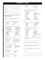
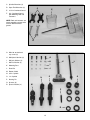
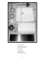
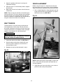
User Manual
Read and understand this manual before using machine.
INDUSTRIAL SHAPER
Model Numbers
48115
48120
®
C
US
STEEL CITY TOOL WORKS
VER. 1.07
Manual Part No. OR73436
w Steel City
signed, tested, and
de
en
be
s
ha
er
ap
sh
s
hi
T
Industrial Shaper.
n properly
he
W
d.
in
m
in
,
er
om
st
cu
inspected with you, the
ovide you with years
pr
ill
w
er
ap
sh
ur
yo
d,
used and maintaine
ed by one of
ck
ba
is
it
hy
w
is
ch
hi
w
of trouble free service,
nties in the business.
ra
ar
w
ry
ne
hi
ac
m
t
es
ng
the lo
e Steel City’s
th
in
ts
uc
od
pr
y
an
m
of
This shaper is just one
is proof of our
d
an
ry
ne
hi
ac
m
ng
ki
or
family of woodw
omer satisfaction.
commitment to total cust
cellence each and
ex
r
fo
ve
ri
st
to
ue
in
nt
co
At Steel City we
customer. For
r
ou
u,
yo
of
n
io
in
op
e
every day and value th
City Tool Works, please
l
ee
St
or
er
ap
sh
ur
yo
t
comments abou
tytoolworks.com .
ci
el
te
.s
w
w
w
at
te
si
eb
visit our w
rchasing your ne
pu
r
fo
U
O
Y
K
N
A
H
T
2
TABLE OF CONTENTS
INTRODUCTION
SECTION 1
Warranty .................................................................................................................................................4
SECTION 2
Product Specifications ............................................................................................................................7
SECTION 3
Accessories and Attachments ................................................................................................................7
SECTION 4
Definition of Terms ..................................................................................................................................7
SECTION 5
Feature Identification ..............................................................................................................................8
SECTION 6
General Safety........................................................................................................................................9
SECTION 7
Product Safety ......................................................................................................................................11
SECTION 8
Electrical Requirements........................................................................................................................12
SECTION 9
Unpacking & Inventory..........................................................................................................................14
SECTION 10
Assembly ..............................................................................................................................................19
SECTION 11
Adjustments ..........................................................................................................................................26
SECTION 12
Operations ............................................................................................................................................28
SECTION 13
Maintenance .........................................................................................................................................30
SECTION 14
Troubleshooting ....................................................................................................................................31
SECTION 15
Parts List...............................................................................................................................................32
INTRODUCTION
This user manual is intended for use by anyone working with this machine. It should be kept available
for immediate reference so that all operations can be performed with maximum efficiency and safety.
Do not attempt to perform maintenance or operate this machine until you have read and understand the
information contained in this manual.
The drawings, illustrations, photographs, and specifications in this user manual represent your machine
at time of print. However, changes may be made to your machine or this manual at any time with no
obligation to Steel City Tool Works.
3
WARRANTY
STEEL CITY TOOL WORKS
5 YEAR LIMITED WARRANTY
Steel City Tool Works, LLC (“SCTW”) warrants all “STEEL CITY TOOL WORKS” machinery to be
free of defects in workmanship and materials for a period of 5 years from the date of the original retail
purchase by the original owner. SCTW will repair or replace, at its expense and at its option, any
SCTW machine, machine part, or machine accessory which in normal use has proven to be defective,
provided that the customer returns the product, shipping prepaid, to an authorized service center with
proof of purchase and provides SCTW with a reasonable opportunity to verify the alleged defect by
inspection. This warranty does not apply to defects due directly or indirectly to misuse, abuse,
negligence, accidents, or lack of maintenance, or to repairs or alterations made or specifically authorized
by anyone other than SCTW. Normal wear components are also excluded under this coverage. Every
effort has been made to ensure that all SCTW machinery meets the highest quality and durability
standards. We reserve the right to change specifications at any time due to our commitment to
continuous improvement of the quality of our products.
EXCEPT AS SET FORTH ABOVE, SCTW MAKES NO EXPRESS OR IMPLIED REPRESENTATIONS OR WARRANTIES WITH RESPECT TO ITS MACHINERY, OR ITS CONDITION,
MERCHANTABILITY, OR FITNESS FOR ANY PARTICULAR PURPOSE OR USE. SCTW
FURNISHES THE ABOVE WARRANTIES IN LIEU OF ALL OTHER WARRANTIES, EXPRESS
OR IMPLIED, INCLUDING THE WARRANTIES OF MERCHANTABILITY AND FITNESS FOR A
PARTICULAR PURPOSE, WHICH ARE HEREBY SPECIFICALLY DISCLAIMED.
SCTW SHALL NOT BE LIABLE FOR ANY (A) SPECIAL, INDIRECT, INCIDENTAL, PUNITIVE
OR CONSEQUENTIAL DAMAGES, INCLUDING WITHOUT LIMITATION LOSS OF PROFITS,
ARISING FROM OR RELATED TO THIS WARRANTY, THE BREACH OF ANY AGREEMENT OR
WARRANTY, OR THE OPERATION OR USE OF ITS MACHINERY, INCLUDING WITHOUT
LIMITATION DAMAGES ARISING FROM DAMAGE TO FIXTURES, TOOLS, EQUIPMENT,
PARTS OR MATERIALS, DIRECT OR INDIRECT LOSS CAUSED BY ANY OTHER PARTY, LOSS
OF REVENUE OR PROFITS, FINANCING OR INTEREST CHARGES, AND CLAIMS BY ANY
THIRD PERSON, WHETHER OR NOT NOTICE OF SUCH POSSIBLE DAMAGES HAS BEEN
GIVEN TO SCTW; (B) DAMAGES OF ANY KIND FOR ANY DELAY BY OR FAILURE OF SCTW
TO PERFORM ITS OBLIGATIONS UNDER THIS AGREEMENT; OR (C) CLAIMS MADE A
SUBJECT OF A LEGAL PROCEEDING AGAINST SCTW MORE THAN ONE (1) YEAR AFTER
SUCH CAUSE OF ACTION FIRST AROSE.
The validity, construction and performance of this Warranty and any sale of machinery by SCTW shall
be governed by the laws of the Commonwealth of Pennsylvania, without regard to conflicts of laws provisions of any jurisdiction. Any action related in any way to any alleged or actual offer, acceptance or
sale by SCTW, or any claim related to the performance of any agreement including without limitation
this Warranty, shall take place in the federal or state courts in Allegheny County, Pennsylvania.
STEEL CITY TOOL WORKS
4
WARRANTY CARD
Name ________________________________________________
Street _______________________________________________
8.
Apt. No. ______________________________________________
City _________________________ State ______ Zip __________
___ Advance
Phone Number_________________________________________
E-Mail ________________________________________________
9.
Model No.: ___________________________________________
Serial No. _____________________________________________
CUT HERE
3.
4.
___ Horizontal Boring Machine
___ Lathe
___ Mortiser
___ Planer
___ Panel Saw
___ Power Feeder
Where did you purchase your STEEL CITY machine?
Store: ____________________________________________
___ Radial Arm Saw
___ Spindle Sander
___ Shaper
___ Table Saw
City:______________________________________________
___ Vacuum Veneer Press
___ Wide Belt Sander
Other____________________________________________
How did you first learn of Steel City Tool Works?
___ Advertisement
___ Mail Order Catalog
___ Web Site
___ Friend
___ Local Store
Other_______________________
11. Which benchtop tools do you own? Check all that apply.
___ Belt Sander
___ Belt / Disc Sander
___ Drill Press
___ Band Saw
___ Grinder
___ Mini Jointer
___ Mini Lathe
___ Scroll Saw
___ Spindle / Belt Sander
Other______________________
Which of the following magazines do you subscribe to?
___ American Woodworker
––– Cabinetmaker
___ American How-To
___ Family Handyman
___
___
___
___
___
___
___
___
___
___ Fine Woodworking
___ Old House Journal
___ Popular Science
___ Today’s Homeowner
___ Woodcraft
___ Woodshop News
___ Woodwork
___ Woodworker’s Journal
Other_________________
Fine Homebuilding
Journal of Light Construction
Popular Mechanics
Popular Woodworking
WOOD
WOODEN Boat
Woodsmith
Woodworker
Workbench
12. Which portable / hand held power tools do you own?
Check all that apply.
___ Biscuit Jointer
___ Belt Sander
___ Dust Collector
___ Circular Saw
___ Detail Sander
___ Drill / Driver
___ Miter Saw
___ Orbital Sander
___ Palm Sander
___ Portable Thickness Planer
___ Saber Saw
___ Reciprocating Saw
___ Router
Other_______________________
13. What machines / accessories would you like to see added to the
STEEL CITY line?
Which of the following woodworking / remodeling shows do
you watch?
___ Backyard America
____________________________________________________
____________________________________________________
___ The American Woodworker
___ Home Time
___ The New Yankee Workshop
___ This Old House
___ Woodwright’s Shop
Other__________________________________________
5.
How many Steel City machines do you own? _____________
___ Dust Collection
___ Jointer
The following information is given on a voluntary basis
and is strictly confidential.
2.
___ Master Craftsman
10. What stationary woodworking tools do you own?
Check all that apply.
___ Air Compressor
___ Band Saw
___ Drill Press
___ Drum Sander
Product Description:_____________________________________
1.
How would you rank your woodworking skills?
___ Simple
___ Intermediate
14. What new accessories would you like to see added?
____________________________________________________
____________________________________________________
What is your annual household income?
___ $20,000 to $29,999
___ $30,000 to $39,999
___ $40,000 to $49,999
___ $50,000 to $59,999
___ $60,000 to $69,999
___ $80,000 to $89,999
15. Do you think your purchase represents good value?
___Yes
___ 70,000 to $79,999
___ $90,000 +
___ No
16. Would you recommend STEEL CITY products to a friend?
6.
___ Yes
What is your age group?
___ 20 to 29 years
___ 40 to 49 years
___ 60 to 69 years
___ 30 to 39 years
___ 50 to 59 years
___ 70 + years
___ No
17. Comments:
____________________________________________________
____________________________________________________
7.
____________________________________________________
____________________________________________________
____________________________________________________
How long have you been a woodworker?
___ 0 to 2 years
___ 2 to 8 years
___ 8 to 20 years
___ over 20 years
5
FOLD ON DOTTED LINE
PLACE
STAMP
HERE
Steel City Tool Works
P.O. Box 10529
Murfreesboro, TN 37129
FOLD ON DOTTED LINE
6
PRODUCT SPECIFICATIONS
Spindles Furnished
3/4”, 1”
Voltage
230V
Spindle Speeds
7000 / 10,000 RPM
Phase
Single
Capacity Under Nut
3 1/2”
Hertz
60
Spindle Travel
3”
RPM
3450
Table Size (with extension)
31” x 28 1/2”
Table Height
34 “
Insert Openings
1-3/8”, 2-3/4”, 4”, 5”
Footprint
23-1/4” x 20-3/4”
Table T-Slot
3/4” x 3/8”
Width
28-1/2”
Forward and Reversing
Yes
Depth
31”
Fence
Wood Laminate
Height
48”
Router Collet
Yes (1/4”, 1/2”)
Net Weight
370 lbs.
Dust Port Size
4”
PRODUCT DIMENSIONS
SHIPPING DIMENSIONS
MOTOR
Width
24-1/2”
Type
Induction, TEFC
Depth
29-1/2”
Horsepower
3HP
Height
40”
Amps
14
Gross Weight
395 lbs.
ACCESSORIES AND ATTACHMENTS
There are a variety of accessories available for your Steel City Product. For more information on
any accessories associated with this and other machines, please contact your nearest Steel City
distributor, or visit our website at: www.steelcitytoolworks.com.
DEFINITION OF TERMS
Arbor – A shaft, driven by the shaper motor that turns
the cutting tools.
Miter gauge – A tool that slides in a slot on the table.
A miter gauge can be adjusted to different angles and is
used to slide the stock past the cutterhead.
Collet – The sleeve that grips the shank of a router bit.
Pitch – A sticky sap based residue that comes from
wood products.
Featherboard – A piece of wood with thin “fingers” that
hold a board against a fence or down against the table.
Runout – The amount of wobble in the spindle.
Fence – A straight guide used to keep a board a set
distance from the cutterhead.
Template – A pattern to guide the marking or cutting of
a shape.
Kickback – When a workpiece is thrown back, in the
opposite direction the cutter is turning.
7
FEATURE IDENTIFICATION
D
D
C
E
F
B
G
H
A
A. Raise/Lower Handwheel
B. Arbor Stabilizer Knob
C. Fence
D. Fence Lock Knobs
E. Miter Gauge
F.
Power Switch
G. Cutterhead Rotation Switch
H. Adjustable Depth Scale
8
GENERAL SAFETY
!
WARNING
!
WARNING
TO AVOID serious injury and damage to the machine,
read and follow all Safety and Operating Instructions
before assembling and operating this machine.
This manual is not totally comprehensive. It does not
and can not convey every possible safety and operational problem which may arise while using this
machine. The manual will cover many of the basic and
specific safety procedures needed in an industrial environment.
Exposure to the dust created by power sanding, sawing, grinding, drilling and other construction activities
may cause serious and permanent respiratory or
other injury, including silicosis (a serious lung disease), cancer, and death. Avoid breathing the dust,
and avoid prolonged contact with dust. The dust
may contain chemicals known to the State of
California to cause cancer, birth defects or other
reproductive harm.
All federal and state laws and any regulations having
jurisdiction covering the safety requirements for use of
this machine take precedence over the statements in
this manual. Users of this machine must adhere to all
such regulations.
Some examples of these chemicals are:
• Lead from lead-based paints.
• Crystalline silica from bricks, cement and other
masonry products.
• Arsenic and chromium from chemically-treated
lumber.
Below is a list of symbols that are used to attract your
attention to possible dangerous conditions.
!
This is the safety alert symbol. It is used to alert you to
potential personal injury hazards. Obey all safety messages that follow this symbol to avoid possible injury or
death.
!
Always operate tool in well ventilated area and provide for proper dust removal. Use a dust collection
system along with an air filtration system whenever
possible. Always use properly fitting NIOSH/OSHA
approved respiratory protection appropriate for the
dust exposure, and wash exposed areas with soap
and water.
DANGER
Indicates an imminently hazardous situation which, if
not avoided, WILL result in death or serious injury.
!
1. To avoid serious injury and damage to the machine,
read the entire User Manual before assembly and
operation of this machine.
WARNING
Indicates a potentially hazardous situation which, if not
avoided, COULD result in death or serious injury.
!
CAUTION
!
WARNING
Indicates a potentially hazardous situation, if not avoided, MAY result in minor or moderate injury. It may also
be used to alert against unsafe practices.
2. ALWAYS wear eye protection. Any machine can
throw debris into the eyes during operations,
which could cause severe and permanent eye
damage. Everyday eyeglasses are NOT safety
glasses. ALWAYS wear Safety Goggles (that
comply with ANSI standard Z87.1) when operating power tools.
CAUTION
CAUTION used without the safety alert symbol indicates a potentially hazardous situation which, if not
avoided, may result in property damage.
NOTICE
This symbol is used to alert the user to useful information about proper operation of the machine.
9
!
11. DO NOT FORCE the machine to perform an operation for which it was not designed. It will do a safer
and higher quality job by only performing operations
for which the machine was intended.
WARNING
12. DO NOT stand on a machine. Serious injury could
result if it tips over or you accidentally contact any
moving part.
3. ALWAYS wear hearing protection. Plain cotton is
not an acceptable protective device. Hearing
equipment should comply with ANSI S3.19
Standards.
!
13. DO NOT store anything above or near the machine.
14. DO NOT operate any machine or tool if under the
influence of drugs, alcohol, or medication.
WARNING
15. EACH AND EVERY time, check for damaged parts
prior to using any machine. Carefully check all
guards to see that they operate properly, are not
damaged, and perform their intended functions.
Check for alignment, binding or breakage of all
moving parts. Any guard or other part that is damaged should be immediately repaired or replaced.
4. ALWAYS wear a NIOSH/OSHA approved dust
mask to prevent inhaling dangerous dust or airborne particles.
16. Ground all machines. If any machine is supplied
with a 3-prong plug, it must be plugged into a 3contact electrical receptacle. The third prong is
used to ground the tool and provide protection
against accidental electric shock. DO NOT remove
the third prong.
5. ALWAYS keep the work area clean, well lit, and
organized. DO NOT work in an area that have slippery floor surfaces from debris, grease, and wax.
6. ALWAYS unplug the machine from the electrical
receptacle when making adjustments, changing
parts or performing any maintenance.
17. Keep visitors and children away from any machine.
DO NOT permit people to be in the immediate work
area, especially when the machine is operating.
7. AVOID ACCIDENTAL STARTING. Make sure that
the power switch is in the “OFF” position before
plugging in the power cord to the electrical
receptacle.
!
18. KEEP protective guards in place and in working
order.
19. MAINTAIN your balance. DO NOT extend yourself
over the tool. Wear oil resistant rubber soled shoes.
Keep floor clear of debris, grease, and wax.
WARNING
20. MAINTAIN all machines with care. ALWAYS KEEP
machine clean and in good working order. KEEP all
blades and tool bits sharp.
21. NEVER leave a machine running, unattended. Turn
the power switch to the OFF position. DO NOT
leave the machine until it has come to a complete
stop.
8. AVOID a dangerous working environment. DO
NOT use electrical tools in a damp environment
or expose them to rain or moisture.
!
22. REMOVE ALL MAINTENANCE TOOLS from the
immediate area prior to turning the machine ON.
WARNING
23. SECURE all work. When it is possible, use clamps
or jigs to secure the workpiece. This is safer than
attempting to hold the workpiece with your hands.
24. STAY ALERT, watch what you are doing, and use
common sense when operating any machine. DO
NOT operate any machine tool while tired or under
the influence of drugs, alcohol, or medication. A
moment of inattention while operating power tools
may result in serious personal injury.
9. CHILDPROOF THE WORKSHOP AREA by
removing switch keys, unplugging tools from the
electrical receptacles, and using padlocks.
10. DO NOT use electrical tools in the presence of
flammable liquids or gasses.
10
25. USE ONLY recommended accessories. Use of
incorrect or improper accessories could cause serious injury to the operator and cause damage to the
machine. If in doubt, DO NOT use it.
28. SAVE these instructions and refer to them frequently and use them to instruct other users.
29. Information regarding the safe and proper operation
of this tool is also available from the following
sources:
26. THE USE of extension cords is not recommended
for 230V equipment. It is better to arrange the
placement of your equipment and the installed
wiring to eliminate the need for an extension cord.
If an extension cord is necessary, refer to the chart
in the Grounding Instructions section to determine
the minimum gauge for the extension cord. The
extension cord must also contain a ground wire and
plug pin.
Power Tool Institute
1300 Summer Avenue
Cleveland, OH 44115-2851
www.powertoolinstitute.org
National Safety Council
1121 Spring Lake Drive
Itasca, IL 60143-3201
American National Standards Institute
25 West 43rd Street, 4th floor
New York, NY 10036
www.ansi.org
27. Wear proper clothing, DO NOT wear loose clothing,
gloves, neckties, or jewelry. These items can get
caught in the machine during operations and pull
the operator into the moving parts. Users must
wear a protective cover on their hair, if the hair is
long, to prevent it from contacting any moving parts.
ANSI 01.1 Safety Requirements for
Woodworking Machines, and the U.S. Department
of Labor regulations
www.osha.gov
PRODUCT SAFETY
1. Serious personal injury may occur if normal safety
precautions are overlooked or ignored. Accidents
are frequently caused by lack of familiarity or failure
to pay attention. Obtain advice from supervisor,
instructor, or another qualified individual who is
familiar with this machine and its operations.
6. Safety decals are on this machine to warn and
direct you to how to protect yourself or visitors from
personal injury. These decals MUST be maintained
so that they are legible. REPLACE decals that are
not legible.
7. DO NOT leave the unit plugged into the electrical
outlet. Unplug the unit from the outlet when not in
use and before servicing, performing maintenance
tasks, or cleaning.
2. Every work area is different. Always consider safety first, as it applies to your work area. Use this
machine with respect and caution. Failure to do so
could result in serious personal injury and damage
to the machine.
8. ALWAYS turn the power switch “OFF” before
unplugging the shaper.
3. Prevent electrical shock. Follow all electrical and
safety codes, including the National Electrical Code
(NEC) and the Occupational Safety and Health
Regulations (OSHA). All electrical connections and
wiring should be made by qualified personnel only.
!
!
WARNING
9. DO NOT handle the plug or shaper with
wet hands.
WARNING
10. USE accessories only recommended by Steel City.
4. TO REDUCE the risk of electrical shock. DO
NOT use this machine outdoors. DO NOT
expose to rain or moisture. Store indoors in a
dry area.
11. DO NOT pull the shaper by the power cord. NEVER
allow the power cord to come in contact with sharp
edges, hot surfaces, oil or grease.
12. DO NOT unplug the shaper by pulling on the power
cord. ALWAYS grasp the plug, not the cord.
5. STOP using this machine, if at any time you experience difficulties in performing any operation.
Contact your supervisor, instructor or machine
service center immediately.
13. REPLACE a damaged cord immediately. DO NOT
use a damaged cord or plug.
11
14. DO NOT use the shaper as a toy. DO NOT use
near or around children.
23. SET UP operations whenever possible to have the
cutters under the workpiece.
15. KEEP hands away from cutting tool.
24. When shaping with a starting pin and rub collar,
BE SURE that the workpiece is of sufficient size to
insure control. It is best to shape a larger piece
and then cut to size on a table saw.
16. NEVER run stock between the fence and the cutter.
17. ALWAYS use a miter gauge and clamp attachment
when shaping small pieces. The fence should be
removed during this operation.
25. BE SURE that there is sufficient bearing surface of
the workpiece on the rub collar to insure support
throughout the operation.
18. ALWAYS feed against the rotation of the cutter.
26. MAKE SURE cutters are properly secured before
starting shaper.
19. The wooden fence halves SHOULD BE adjusted
endwise so the opening is never more than is
required to clear the cutter.
20. KEEP cutters sharp and free from rust and pitch.
27. USE guards, guides, and hold-down wherever
possible.
21. ONLY use flat workpieces in the shaper, never use
warped or twisted lumber.
28. ALWAYS use proper speed setting for the cutter
being used.
22. NEVER take off too much material in one pass.
Make several lighter passes.
29. DO NOT perform any operation freehand. Use the
fence for straight shaping, the miter gauge for end
shaping, and a starting pin and collar for curve
shaping.
ELECTRICAL REQUIREMENTS
!
WARNING
The switch provided with your shaper is designed for
230 volt single phase usage only. The switch has a
plug that is designed to plug into a 230 volt outlet.
There are many different configurations for 230 volt
outlets, so it is conceivable that the configuration of the
plug may not match the configuration of your existing
outlet. If this is the case, you will have to replace the
plug with a UL/CSA approved plug that matches the
configuration of your 230V outlet.
To reduce the risk of electric shock, follow all electrical and safety codes, including the National Electric
Code (NEC) and the Occupational Safety and Health
Regulations (OSHA). All electrical connections and
wiring should be made by qualified personnel only.
12
GROUNDING INSTRUCTIONS
!
The motor supplied with your machine is a 230 volt,
single phase motor. Never connect the green or ground
wire to a live terminal.
WARNING
A machine with a 230 volt plug should only be connected to an outlet having the same configuration as the
plug.
This machine MUST BE GROUNDED while in use to
protect the operator from electric shock.
EXTENSION CORDS
In the event of a malfunction or breakdown, GROUNDING provides the path of least resistance for electric
current and reduces the risk of electric shock. The plug
MUST be plugged into a matching electrical receptacle
that is properly installed and grounded in accordance
with ALL local codes and ordinances.
!
If a plug is provided with your machine DO NOT modify
the plug. If it will not fit your electrical receptacle, have
a qualified electrician install the proper connections to
meet all electrical codes local and state. All connections
must also adhere to all of OSHA mandates.
WARNING
To reduce the risk of fire or electrical shock, use the
proper gauge of extension cord. When using an
extension cord, be sure to use one heavy enough to
carry the current your machine will draw.
IMPROPER ELECTRICAL CONNECTION of the equipment-grounding conductor can result in risk of electric
shock. The conductor with the green insulation (with or
without yellow stripes) is the equipment-grounding conductor. DO NOT connect the equipment-grounding conductor to a live terminal if repair or replacement of the
electric cord or plug is necessary.
The smaller the gauge-number, the larger the diameter
of the extension cord is. If in doubt of the proper size of
an extension cord, use a shorter and thicker cord. An
undersized cord will cause a drop in line voltage resulting in a loss of power and overheating.
Check with a qualified electrician or service personnel if
you do not completely understand the grounding
instructions, or if you are not sure the tool is properly
grounded.
USE ONLY a 3-wire extension cord that has a 3-prong
grounding plug and a 3-pole receptacle that accepts the
machine’s plug.
!
If you are using an extension cord outdoors, be sure it
is marked with the suffix “W-A” (“W” in Canada) to indicate that it is acceptable for outdoor use.
PLUGS/RECEPTACLES
!
CAUTION
Make certain the extension cord is properly sized, and
in good electrical condition. Always replace a worn or
damaged extension cord immediately or have it
repaired by a qualified person before using it.
WARNING
Protect your extension cords from sharp objects, excessive heat, and damp or wet areas.
• Electrocution or fire could result if this machine is
not grounded properly or if the electrical configuration does not comply with local and state electrical
codes.
MINIMUM RECOMMENDED GAUGE FOR EXTENSION CORDS (AWG)
230 VOLT OPERATION ONLY
• MAKE CERTAIN the machine is disconnected
from power source before starting any electrical
work.
• MAKE SURE the circuit breaker does not exceed
the rating of the plug and receptacle.
13
25’ LONG
50’ LONG
100’ LONG
0 to 6 Amps
16 AWG
16 AWG
14 AWG
6 to 8 Amps
16 AWG
16 AWG
12 AWG
8 to 12 Amps
14 AWG
14 AWG
10 AWG
12 to 15 Amps
12 AWG
12 AWG
10 AWG
15 to 20 Amps
10 AWG
10 AWG
Not
recommended
UNPACKING & INVENTORY
!
can be removed by spraying WD-40 on them and
wiping it off with a soft cloth. This may need redone
several times before all of the protective coatings are
removed completely.
WARNING
After cleaning, apply a good quality paste wax to any
unpainted surfaces. Make sure to buff out the wax
before assembly.
• The machine is heavy, two people are required to
unpack and lift.
Compare the items to inventory figures; verify that all
items are accounted for before discarding the shipping
box.
• Use a safety strap to avoid tip over when lifting
machine.
Check shipping carton and machine for damage before
unpackaging. Carefully remove packaging materials,
parts and machine from shipping carton. Always check
for and remove protective shipping materials around
motors and moving parts. Lay out all parts on a clean
work surface.
!
WARNING
If any parts are missing, do not attempt to plug in the
power cord and turn “ON” the machine. The machine
should only be turned “ON” after all the parts have been
obtained and installed correctly. For missing parts,
contact Steel City at 1-877-SC4-TOOL.
Remove any protective materials and coatings from all
of the parts and the shaper. The protective coatings
A. Main Fence Casting
B. Laminated Fence Halves (2)
B
A
14
C. Spindle Wrenches (2)
D. Open End Wrenches (2)
C
F.
F
E
E. 3-1/2-in Overhead Guard
6-in Overhead Guard
with Mounting Rod and
Fasteners
NOTE: Rod and fasteners are
interchangeable and are to be
used on both overhead
guards.
D
G. M6 x 20 socket head
cap screw (4)
H
M6 Nylock Hex Nut (4)
G
I.
M6 Lock Washer (4)
H
J.
M6 Flat Washer (4)
K
L
I
K. Mounting Post
J
L. Draw Bar
M. Router Collett
N. 3/4-in. Spindle
O. 1-in. Spindle
O
N
Q
P. Starting Pin
Q. Spacers (6)
R. Special Washer (2)
M
P
R
15
W
V
U
S
X
Z
AA
T
Y
S.
Fence Lock Knobs with Flat Washers
T.
Top Cover Lock Knobs with Flat Washers
U.
Top Cover
V.
Guard Mounting Bracket
W. Hold Down Bracket
X.
Barrier Guard with Shaft
Y.
Chip Deflector with Shaft
Z.
Extension Rod
AA. Lock Handles with Flat Washers (2)
16
HH
BB
CC
DD
BB
BB
FF
EE
GG
BB. Table Inserts (3)
CC. Dust Chute (Small Half)
DD. Dust Chute (Large Half)
EE. Motor Cover
FF. Handwheel
GG. Extension Wing
HH. Miter Gauge Assembly
17
OO
PP
II
JJ
KK
LL
QQ
RR
MM
SS
NN
II.
M5 x 10mm Pan Head Screw(6)
JJ.
M5 Flat Washer(6)
KK. M5 Lock Washer(6)
LL.
M6 x 12mm Pan Head Screw(6)
MM. M6 Flat Washer(6)
NN. M6 Lock Washer(6)
OO. M8 x 20mm Socket Head Cap Screw
PP. M10 x 65mm Socket Head Cap Screw
QQ. M10 Flat Washer(2)
RR. M10 Lock Washer
SS. M10 Hex Nut
18
ASSEMBLY
Before beginning assembly, take note of the following
precautions and suggestions
In order to connect to a dust collection system, you will
need to attach the dust port (A) to the rear of the
machine using four M5 x 10mm pan head screws.
SEE FIG. 1.
The shaper is bolted to the pallet. Before attempting any of the assembly procedures remove all of
the loose parts and hardware from the inside of the
shaper and unbolt the machine from the pallet.
Fig. 1
A
CAUTION
FLOOR
!
This tool distributes a large amount of weight over a
small area. Make certain that the floor is capable of
supporting both the weight of the machine and the
operator. The floor should also be a level surface.
If the unit wobbles or rocks once in place, be sure to
eliminate by using shims.
WORKING CLEARANCES
Take into consideration the size of the material to be
processed. Make sure that you allow enough space for
you to operate the machine freely.
REMOVING SHIPPING STRAP
There is a metal strap (A) located inside of the cabinet
that is bolted to both the motor and the cabinet to help
prevent damage during shipping. This strap must be
removed prior to operating the shaper. SEE FIG. 2.
OUTLET PLACEMENT
Outlets should be located close enough to the machine
so that the power cord or extension cord is not in an
area where it would cause a tripping hazard. Be sure
to observe all electrical codes if installing new circuits
and/or outlets.
!
Fig. 2
B
WARNING
A
• DO NOT assemble the Shaper until you are certain
that the machine is not plugged in and the power
switch is in the OFF position.
• DO NOT connect the machine to the power source
until the machine is completely assembled and you
read and understand the entire User Manual.
C
DUST COLLECTION
Since the Shaper generates a large amount of dust and
wood shavings, using an appropriate Dust Collection
system is highly recommended. Make certain to construct your ducting to achieve optimum airflow and
allow for adequate working clearances.
To remove:
1. Remove the two hex head cap screws (B) located
on the outside of the shaper. SEE FIG. 2.
2. A third bolt (C) is located behind the motor attaching the lower end of the strap to the motor plate.
Remove using an open end wrench
19
2. Install the larger half of the dust chute, making sure
that the notch (A) lines up with the shaft (B).
Fasten into place using four M5 x 10mm pan head
screws, four M5 lock washers, and four M5 flat
washers. SEE FIG. 4.
INSTALLING DUST CHUTE
The dust chute comes in two halves. The smaller piece
fits to the left of the shaft and the larger piece with the
notch cut out, goes to the right of the shaft. To install:
1. Insert the smaller half of the dust chute into the
cabinet and fasten using two M5 x 10mm pan head
screws, two M5 lock washers, and two M5 flat
washers. SEE FIG. 3.
Fig. 4
Fig. 3
A
B
3. Once dust chute is installed, place rubber boot (C)
around the shaft. SEE FIG. 5.
Fig. 5
C
20
ATTACHING SWITCH
INSTALLING MOTOR COVER
The switch is designed to be mounted on a swivel arm
so that it can be put in various positions depending on
the job. To attach
The motor cover provides easy access to the motor and
is located on the side of the shaper. Once all of the
internal parts of the shaper have been assembled, you
can install the motor cover. Attach the motor cover to
the cabinet using six M6 x 12mm pan head screws, six
M6 lock washers and six M6 flat washers. SEE FIG. 8.
1. Insert the arm (A) into the bracket on the saw and
line up the hole on the arm (B) with the hole on the
bracket (C). SEE FIG. 6.
Fig. 8
Fig. 6
C
B
A
ATTACHING EXTENSION WING
The shaper has one extension wing that needs to be
mounted before it can be operated.
2. Fasten the swivel arm to the bracket using one M10
x 65mm Socket Head Cap Screw, two M10 flat
washers, one M10 lock washer, and one M10 hex
nut.
To install:
1. Attach the extension wing to the table using three
M10 x 35MM socket head cap screws, three M10
lock washers, and three M10 flat washers.
3. Position the swivel arm so that the other hole in the
swivel arm lines up with one of the three holes in
the bracket (D) and secure in place using one M8 x
20mm socket head cap screw. SEE FIG. 7.
2
Slide the extension wing until the front of the wing
is flush with the main table.
3. Using a straight edge, align the extension wing to
the table and securely tighten the three socket head
cap screws. SEE FIG 9.
Fig. 7
Fig. 9
D
21
3. Insert the draw bar (A) through the bottom of the
quill, making sure that the beveled edge of the
drawbar nut (B) is facing upwards. SEE FIG 12.
ATTACHING HANDWHEEL
The handwheel is used to raise and lower the spindle.
To install:
Fig. 12
1. Line up the keyway in the handwheel with the key
on the shaft.
2. Insert handwheel over the shaft.
3. Secure handwheel to the shaft by tightening set
screw (A). SEE FIG 10.
Fig. 10
A
B
A
INSTALLING SPINDLE
!
4. Use the spindle wrench to hold the top flats on the
spindle while tightening the draw bar nut using an
open end wrench. SEE FIG 13.
WARNING
MAKE CERTAIN THAT THE SHAPER IS DISCONNECTED FROM THE POWER SOURCE.
Fig. 13
1. Select the appropriate spindle for your shaping
operation. This Shaper comes equipped with a 3/4”
spindle, a 1” spindle, and a router collet that
accepts 1/4” and 1/2” router bits.
2. Insert the end of the spindle into quill of the shaper.
MAKE CERTAIN to align the keyway in the spindle
with the tab on the quill. SEE FIG 11.
Fig. 11
KEYWAY
22
SETTING TABLE INSERTS
ATTACHING CUTTERS AND
COLLARS TO SPINDLES
The table inserts are preinstalled at the factory. They
should be adjusted so that the top surface of the insert
is level with the tabletop. If any adjustment is necessary:
!
!
WARNING
MAKE CERTAIN THAT THE SHAPER IS DISCONNECTED FROM THE POWER SOURCE.
WARNING
MAKE CERTAIN THAT THE SHAPER IS DISCONNECTED FROM THE POWER SOURCE.
1. When attaching a cutter, remember to position the
cutter as close to the bottom of the spindle as
possible.
1. Remove the three screws in the top of the insert.
2. Remove both spindle nuts (A) and special washer
(B). SEE FIG 15.
2. With the screws removed, you can see the three
insert leveling screws (A). SEE FIG 14.
Fig. 15
Fig. 14
B
A
D
C
A
3. Decide which collars you will need to use, if any,
and place over the spindle.
3. Using a 6mm hex wrench, turn the adjusting screws
so that the insert sits flush with the table.
4. Attach the cutter (D) to the spindle.
5. Add collar (if any) and then attach the special
washer (B). Figure 15 shows a collar (C) installed
above the cutter.
4. Replace the screws removed in step 1.
!
WARNING
MAKE CERTAIN that the special washer goes on just
before you replace the spindle nuts. This washer prevents the spindle nut(s) from loosening if the cutter is
stalled.
6. Replace spindle nuts (A) and tighten using the
spindle wrenches.
23
6. Attach Guard Mounting Bracket (D) to the Top
Cover (E) using four M6 x 20mm Socket Head Cap
Screws, four M6 flat washers, four M6 lock washers, and four M6 Nylock hex nuts. SEE FIG. 18.
ASSEMBLING FENCE
!
WARNING
MAKE CERTAIN THAT THE SHAPER IS DISCONNECTED FROM THE POWER SOURCE.
Fig. 18
1. Install the fence by placing the main fence casting
(A) on the table surface. SEE FIG 16.
D
Fig. 16
F
F
B
A
E
2. Use the two locking handles (B) provided to secure
the fence casting to the table by threading the
handles into the holes in the table located slightly
behind the spindle opening.
7. With the Guard Mounting Bracket now attached to
the Top Cover, fasten the top cover to the fence
casting using the two supplied Lock Knobs (F) and
flat washers.
3. Attach the laminated wooden fence halves by placing one flat washer (not shown) over the fence lock
knob (A), insert the handle through the hole (B) in
the fence, and thread into the bracket on the back
of the laminated wooden fence half. SEE FIG. 17.
8. There are several types of guards that should be
attached to the shaper fence depending on the
operation that you are performing. Figures 19 and
Fig 20 show how the Barrier Guard (G), the Hold
Down Bracket (H), the Chip Deflector (I), and the
Overhead Guard(J) are attached to the Fence
Assembly SEE FIGS. 19 and 20.
Fig. 17
C
Fig. 19
B
I
A
4. Tighten fence lock knob until the fence half is
securely in place.
H
NOTE: The fence lock handles are spring loaded and
can be adjusted by pulling out on the handle and repositioning on the shaft.
G
5. Repeat steps 3-4 to attach the remaining fence half.
24
NOTICE: Guard segments will need to be repositioned
for the operation being attempted. The guards should
be as close as possible without interfering with the
travel of the workpiece or cutter.
Fig. 20
H
J
25
ADJUSTMENTS
CHANGING SPEEDS
RAISING AND LOWERING
THE SPINDLE
This shaper is constructed with a 2 step pulley on both
the motor pulley (A) and on the spindle pulley (B). This
two step configuration allows for speeds of either 7,000
RPM or 10,000 RPM. With the belt on the larger step
of the motor pulley and the smaller step on the spindle
pulley, the spindle speed will be 10,000 RPM. Conversely, with the belt on the smaller step of the motor
pulley and the larger step on the spindle pulley, the
spindle speed would be 7,000 RPM. The belt can be
moved from one step on the pulley to the other by
simply walking the belt. SEE FIG. 21.
The Spindle can be raised or lowered by loosening the
stabilizer knob (B) and turning the handwheel (C). To
raise the spindle height, turn the handwheel clockwise.
To lower the spindle height, turn the handwheel counterclockwise. The adjustable scale (D) on the front of
the shaper shows the height of the spindle and can be
positioned to set your zero mark at multiple locations.
Once the spindle is in the desired location you can
stabilize the position by turning the knob (B) located on
the side of the machine. SEE FIG. 22.
Fig. 22
Fig. 21
D
A
B
C
B
A
FENCE POSITIONING
!
WARNING
The two faces of the fence are independent of one
another and can be set at different positions to allow for
different shaping tasks. To adjust
The two settings listed above are the only combinations
available for this shaper. DO NOT attempt to skew the
belt so that it rides on either both small pulleys or both
large pulleys. Doing so may result in damage to the
machine and/or injury to the operator.
1. Loosen lock lever (A). SEE FIG 23.
Fig. 23
REVERSING SPINDLE ROTATION
The shaper is equipped with a switch (A) that controls
which way the cutter spins. Turning the switch to left
runs the cutter in the forward direction, while turning it
to the right runs the cutter in the reverse direction.
When the switch is positioned in the middle , as shown
in Fig 22, this is the neutral position. SEE FIG 22.
!
A
WARNING
DO NOT attempt to change the spindle rotation while
the machine is running. Turn the machine “OFF” and
wait for the spindle to come to a complete stop before
changing the rotation.
B
26
2. Adjust the position of the fence by turning the
adjustment knob (B)
FENCE ALIGNMENT
3. When the fence is in the desired position, retighten
the lock lever.
Before using the shaper, it is important to make sure
that the two fence faces are parallel. Use the following
steps to ensure the parallelism of the two fence halves.
4. Repeat this process for the other side of the fence,
if necessary.
1. Use a straight edge that is long enough to span the
length of the entire fence and position it up against
both fence halves (A). SEE FIG 25.
NOTE: There are two sets of holes on the table top for
attaching the fence. The most common set-up positions
the fence so that it runs parallel to the miter slot. The
fence can, however, be rotated 90° from the position by
using the second set of holes in the table top.
Fig. 25
BELT TENSION
The belt tension is set at the factory and should not
need adjustment on initial setup. The belt will need
occasional adjustment as the belt will stretch over time.
The belt should yield 1/4” of deflection when squeezed
together at the midpoint. To adjust belt tension:
!
WARNING
A
MAKE CERTAIN THAT THE SHAPER IS DISCONNECTED FROM THE POWER SOURCE.
1. Loosen the two hex head bolts (A). SEE FIG 24.
2. Slide the motor and bracket assembly (B) away
from the spindle cartridge (C) until the slack is
removed from the belt.
3. Retighten the two hex bolts loosened in step 1.
Fig. 24
B
C
NOTE: Before placing the straight edge up against the
fence, make certain that the fence lock knobs (B) are
securely tightened.
A
2. Adjust the fence faces so that they are as close as
possible to the same parallel position.
27
OPERATIONS
!
SHAPING USING THE FENCE
WARNING
Using the fence is the safest method of shaping. Most
straight cuts that use the fence for support can be performed by following the guidelines below
MAKE CERTAIN THAT THE SHAPER IS DISCONNECTED FROM THE POWER SOURCE.
1. If performing a cut where a portion of the workpiece
is not touched by the cutterhead, both sides of the
fence will be set at the same depth.
!
WARNING
2. When performing a cut where the entire edge of the
workpiece is removed, the fence must be positioned
differently. If the fence halves are kept in line, once
the workpiece passes through the cutterhead, the
shaped edge would no longer be supported against
the fence. To prevent this, the outfeed side of the
fence must be positioned further out to compensate
for the material being removed. Advance the outfeed side of the fence until it contacts the shaped
edge of the workpiece.
ALWAYS wear eye protection. Any machine can
throw debris into the eyes during operations, which
could cause severe and permanent eye damage.
Everyday eyeglasses are NOT safety glasses.
ALWAYS wear Safety Goggles (that comply with
ANSI standard Z87.1) when operating power tools.
!
3.
If using a miter gauge, the infeed side of the fence
MUST be parallel with the miter slot. Also make
certain that the outfeed side of the fence is positioned out of the way so that it does not contact the
workpiece after it passes through the cutterhead.
WARNING
FREEHAND SHAPING
Freehand Shaping is shaping without the use of a miter
gauge or fence. Beginning the cut is the most dangerous part of freehand shaping. Many times when the
workpiece first contacts the cutter, the workpiece will
tend to kickback or jerk, which can surprise the operator. To help reduce the frequency of these incidents
and increase the safety aspect of freehand shaping, a
starting pin is provided with your shaper. This pin will
allow you to anchor and slowly pivot the workpiece into
the cutter at the beginning of the cut. When freehand
shaping, it is always best to use a template jig.
ALWAYS wear a NIOSH/OSHA approved dust mask
to prevent inhaling dangerous dust or airborne
particles.
NOTICE
The following section was designed to give
instructions on the basic operations of this
shaper. However, it is in no way comprehensive
of every shaper application. It is strongly recommended that you read books, trade magazines, or
get formal training to maximize the potential of
your shaper and to minimize the risks.
!
WARNING
Use EXTREME care when freehand shaping. With the
fence removed, more of the cutter is exposed increasing the risk of injury.
To set up the shaper for freehand operation
1. Remove the fence assembly from the shaper
2. Insert the starting pin (A) in the most suitable hole
(B) on the table insert. SEE FIG 26, page 29.
28
Fig. 26
B
USING COLLARS
! WARNING
B
When shaping workpieces that have irregular shapes, it
is essential to use a collar. There are three basic types
of setup for the collar. Each setup has it’s advantages
and disadvantages
A
Below the Cutter
The advantage of the collar being positioned below the
cutter is that the user can see the progress of the cut.
While this method provides a good view of the cut
being made, the disadvantage is that any lifting of the
workpiece, even slightly, will cause the cutter to gouge
the wood and ruin the workpiece. SEE FIG 28.
B
Fig. 28
CUTTER
WORKPIECE
3. Attach the Mounting post (C) to the table using two
provided socket head cap screws and attach overhead (D) guard to the post. SEE FIG. 27.
Fig. 27
COLLAR
COLLAR BELOW THE CUTTERHEAD
Above the Cutter
This type of setup is the safest of the three and produces the most consistent results. Two advantages of
this setup are that
D
C
1. The cut will not be affected by slight variations in
the thickness of the workpiece
2. The workpiece will not be gouged if you accidentally lift it off the table. If the workpiece lifts off the
table, simply run it though the cutter again to produce a finished cut
The only disadvantage of this type of setup is that the
user will not be able to see the cut being made as it will
be on the underside of the workpiece. SEE FIG. 29.
Fig. 29
WORKPIECE
4. Use a hold down jig or rubberized push blocks to
support or guide the workpiece and help protect
your hands from injury.
COLLAR
5. Place the workpiece against the starting pin.
6. Slowly pivot and feed the workpiece into the cutter.
Try to avoid starting your cut on the corner of a
workpiece to help reduce the risk of a kickback.
7. Once the cut is started, the workpiece should be
pulled away from the starting pin.
CUTTER
COLLAR ABOVE THE CUTTER
29
Between two Cutters
Fig. 30
The advantage of this setup is that you can make two
profile cuts in a single pass so it is frequently used
when both edges of the workpiece are to be shaped.
The disadvantage with this method, like the “Below the
Cutter” method, is that any accidental lifting of the
workpiece will cause gouging and ruin the workpiece.
SEE FIG. 30.
CUTTER
COLLAR
WORKPIECE
CUTTER
COLLAR BETWEEN TWO CUTTERS
MAINTENANCE
This shaper requires very little maintenance other than
minor lubrication and cleaning. The following sections
detail what will need to be done in order to assure continued operation of your shaper.
MODEL 48115 ONLY
The tabletop is an unfinished metal surface that, over
time, will accumulate rust if not properly cared for.
When the shaper is not in use, keep a light coat of
WD-40 on the table top as this will help prevent rust
from occurring. If rust has already accumulated on the
table, use WD-40 and a fine steel wool to get rid of the
rust. Using a quality paste wax on the tabletop and
wings is a good preventative measure to help prevent
rust from forming.
LUBRICATION
The shaper has sealed lubricated bearings in the motor
housing and the arbor assembly that do not require any
additional lubrication from the operator.
CLEANING
MODEL 48120 ONLY
Keep the inside of the cabinet clear of saw dust and
wood chips. With the shaper unplugged, vacuum out
the inside of the cabinet or blow out the inside with an
air hose. Be sure to use air pressure no higher than
50 P.S.I. as high pressure air may damage insulation.
The table top is designed to be maintenance free and,
under normal shop conditions, the Titanium Nitrite (TiN)
coating will minimize the chance of rust forming on the
table top. While the distinctive gold color of your Steel
City cast-iron top is an indication that the surface is protected against rust and corrosion, that protection does
not diminish if the gold color is worn away by abrasion
due to normal use over time. A paste wax may be
applied to the table top to give it a shiny appearance.
!
WARNING
Be sure to wear protective eyewear and dust mask
when cleaning out the cabinet of the shaper.
30
TROUBLESHOOTING GUIDE
PROBLEM
LIKELY CAUSE(S)
SOLUTION
The shaper does
not start or the
breaker trips.
1. The supply circuit has low voltage,
or high resistance.
1. If you are unqualified to test voltage, determine circuit
loads, or rewire electrical connections, contact a
qualified electrician.
2. The motor start capacitor is open
or shorted.
2. Unplug the shaper and inspect the capacitor for oily
residue, bubbled plastic, foul odor, and test and replace
accordingly.
3. Forward/reverse switch is in the neutral
position.
3. Make sure the switch is in the forward or reverse
position.
1. The belt-to-pulley ratio is set to 7,000 RPM.
1. Unplug the shaper and move the belt to the 10,000 RPM
pulley position.
2. The extension cord used is the wrong gauge
and has too much resistance, or the supply
circuit has low voltage, or high resistance.
2. Eliminate the extension cord and move the shaper closer
to the wall receptacle. If you are unqualified to test
voltage or determine circuit loads, contact a qualified
electrician.
The drive belt tears
or runs off of the
shaper.
1. The belt tension is too low and the belt has
run off of the pulley.
1. Increase the belt tension to prevent slippage. DO NOT
over tighten the belt tension.
The shaper vibrates,
the spindle is
loose, or the
cutter chatters.
1. The shaper is unstable and wobbles.
1. Stabilize the shaper with the floor, using shims.
2. The spindle, cutter, or router bit spindle
adapter is loose or out of alignment.
2. Reinstall spindle, cutter, or router bit spindle adapter
as outlined.
3. The shaper has a loose motor or spindle
cartridge.
3. Unplug the shaper and carefully look for loose motor,
motor mounts, spindle cartridge, or other parts.
Tighten fasteners as required.
4. The motor or spindle cartridge bearings are
at fault.
4. Replace bearings or spindle cartridge assembly as
required.
The shaper runs
slow.
31
PARTS
32
KEY
NO.
PART
NO.
DESCRIPTION
1A
OR72106
EXTENSION WING
1B
OR72198
EXTENSION WING (TITANIUM FINISH)
KEY
NO.
PART
NO.
DESCRIPTION
1
50
OR72126
WARNING LABEL
1
1
51A
OR72120
TABLE
1
QTY.
QTY.
2
OR90230
M10 FLAT WASHER
3
51B
OR72199
TABLE (TITANIUM FINISH)
1
3
OR90227
M10 LOCK WASHER
3
52
OR72121
TABLE INSERT
1
4
OR94401
M10 x 35mm SOC HEAD CAP SCR
3
53
OR72122
TABLE INSERT
1
5
OR72107
SIDE COVER
1
54
OR72125
TABLE INSERT
1
6
OR94403
STRAIN RELIEF
1
55
OR72124
TABLE INSERT
1
7
OR90320
M6 X 12mm PAN HEAD SCREW
6
56
OR72123
PIN
1
8
OR90502
M6 LOCK WASHER
6
57
OR91756
M5 x 20mm HEX SOC HD SCR
3
9
OR90059
M6 FLAT WASHER
6
58
OR94408
SCREW
3
10
OR91776
M4 X 20mm PAN HEAD SCREW
2
59
OR73401
SHIPPING STRIP
1
11
OR73374
SCALE
1
60
OR73386
INSULATOR
1
12
OR73375
MAGNETIC STRIP
1
61
OR73387
POWER CORD
1
13
OR73376
SCALE STRIP
1
62
OR73388
INSULATOR
1
14
OR90078
HEX NUT M4
2
63
OR73389
POWER CORD
1
15
OR73377
SCALE PIN
2
65
OR73390
SWITCH ASSY CONST. OF;REF 66 TO REF 79
1
16
OR90308
M8 x 20mm HEX BOLT
1
66
OR90761
M5 X 10mm PAN HEAD SCREW
8
17
OR91499
M8 FLAT WASHER
1
67
OR90145
M5 LOCK WASHER
8
18
OR91500
M8 LOCK WASHER
1
68
OR90462
M5 FLAT WASHER
8
19
OR73378
STAND BODY
1
69
OR73391
SWITCH’S BACK BOX
1
20
OR70321
SPEC PLATE
1
70
OR73392
SWITCH’S BOX WASHER
1
21
OR70484
NAME PLATE
1
71
OR73393
SWITCH’S FRONT BOX
1
22
OR93823
RIVET
4
72
OR72109
SWITCH BOX GASKET
1
23
OR72111
COVER
1
73
OR72112
FOR / REV SWITCH
1
24
OR91828
M4.8 X 16mm PAN HEAD SELF TAPPING SCREW
3
74
OR72108
3HP MAGNETIC SWITCH
1
25
OR72115
COVER
1
75
OR73394
PLASTIC BLOCK
2
26
OR91828
M4.8 X 16mm PAN HEAD SELF TAPPING SCREW
3
76
OR91778
M5 X 16mm PAN HEAD SCREW
4
27
OR90462
M5 FLAT WASHER
6
77
OR90145
M5 LOCK WASHER
4
28
OR90145
M5 LOCK WASHER
6
78
OR90462
M5 FLAT WASHER
4
29
OR90761
M5 X 10mm PAN HEAD SCREW
6
79
OR73395
SWITCH BRACKET
2
30
OR73379
FLOOR PANEL-1
1
80
OR73396
SWITCH MOUNT ASSY CONST. OF REF 81 TO REF 94
1
31
OR73380
FLOOR PANEL-2
1
81
OR90228
M10 HEX NUT
1
32
OR73381
FLOOR PANEL-3
1
82
OR90227
M10 LOCK WASHER
1
33
OR73382
DOOR
1
83
OR73397
FLAT HEAD RIVETED NUTS
4
34
OR73383
4” DUST PORT
1
84
OR73398
SWITCH MOUNT BRACKET
1
35
OR90761
M5 X 10mm PAN HEAD SCREW
4
85
OR90230
M10 FLAT WASHER
2
36
OR90863
M5 x 12mm PAN HEAD SCREW
8
86
OR94815
M10 x 65mm HEX SOC HD SCR
1
37
OR90462
M5 FLAT WASHER
8
87
OR73399
LOCK KNOB
1
38
OR90145
M5 LOCK WASHER
8
88
OR91499
M8 FLAT WASHER
1
39
OR91563
M5 HEX NUT
8
89
OR90502
M6 LOCK WASHER
4
40
OR72117
HINGE
2
90
OR91826
M6 X 16mm PAN HEAD SCREW
4
41
OR73384
DOOR LOCK HANDLE
1
91
OR91826
M6 X 16mm PAN HEAD SCREW
4
42
OR94407
M8 THIN HEX NUT
1
92
OR90502
M6 LOCK WASHER
4
43
OR73385
DOOR LOCK
1
93
OR90059
M6 FLAT WASHER
4
44
OR91499
M8 FLAT WASHER
1
94
OR73400
SWITCH SUPPORT BRACKET
1
45
OR91500
M8 LOCK WASHER
1
95
OR72127
WARNING LABEL
1
46
OR91501
M8 HEX NUT
1
96
OR91501
M8 HEX NUT
2
47
OR90230
M10 FLAT WASHER
4
97
OR91500
M8 LOCK WASHER
2
48
OR90227
M10 LOCK WASHER
4
98
OR91499
M8 FLAT WASHER
4
49
OR90777
M10 x 25mm SOC HEAD CAP SCR
4
99
OR93381
M8 x 20mm HEX SOC HD SCR
2
33
34
KEY
NO.
PART
NO.
DESCRIPTION
QTY.
KEY
NO.
PART
NO.
DESCRIPTION
101A
OR70426
101B
OR70373
MOTOR (3HP,230VAC,15AMP,1 PHASE)
1
140
OR93912
M12 LOCK WASHER
MOTOR SPEC PLATE
1
141
OR93526
M12 x 45mm HEX HEAD SCREW
101C
4
OR72129
CAPACITOR
1
142
OR94412
THRUST BEARING (51203)
1
102
OR72130
MOTOR PULLEY
1
143
OR94413
M16 FLAT WASHER
1
103
OR90222
M6 x 10mm HEX SOC SET SCREW
2
144
OR93922
M16 x 1.5 NYLOK NUT
1
104
OR72131
BELT
1
145
OR72141
WORM SHAFT
1
105
OR94409
4.76mm x 4.76mm x 32mm KEY
1
146
OR90219
5mm x 5mm x 30mm KEY
1
106
OR93891
M8 x 40mm HEX BOLT
4
147
OR72142
SHAFT MOUNT
1
107
OR94816
M8 BIG FLAT WASHER
4
148
OR94414
M6 x 5mm HEX SOC SET SCREW
1
108
OR94816
M8 BIG FLAT WASHER
4
149
OR91499
M8 FLAT WASHER
3
3
QTY.
4
109
OR91500
M8 LOCK WASHER
4
150
OR91500
M8 LOCK WASHER
110
OR91501
M8 HEX NUT
4
151
OR91752
M8 x 25mm HEX BOLT
3
111
OR72132
MOTOR MOUNT PLATE
1
152
OR72143
BUSHING
1
112
OR90230
M10 FLAT WASHER
2
153
OR72144
BUSHING
2
113
OR90227
M10 LOCK WASHER
2
154
OR94415
COPPER FLAT WASHER
1
114
OR93546
M10 x 40mm HEX HEAD BOLT
2
155
OR94416
WAVE WASHER
1
115
OR93381
M8 x 20mm HEX SOC HD SCR
2
156
OR72145
SLEEVE
1
116
OR91500
M8 LOCK WASHER
2
157
OR91816
M6 X 8mm SETSCREW
2
117
OR91499
M8 FLAT WASHER
2
158
OR72146
HANDWHEEL
1
118
OR72135
SUPPORT PLATE
1
159
OR91764
M5 x 10mm HEX SOC SET SCREW
1
119
OR72136
SUPPORT PIN
1
160
OR72147
HANDLE
1
120
OR72133
SUPPORT WASHER
1
161
OR94412
THRUST BEARING (51203)
1
121
OR94410
SPRING
1
162
OR72148
GEAR
1
122
OR73402
SUPPORT WASHER
1
163
OR94061
5MM x 5mm x 10mm KEY
1
123
OR90499
M16 HEX NUT
3
164
OR72149
ELEVATION LEAD SCREW
1
124
OR94413
M16 FLAT WASHER
2
165
OR91746
M10 x 45mm HEX HEAD BOLT
1
126
OR72138
GIB
1
166
OR90227
M10 LOCK WASHER
1
127
OR94821
M5 X 8mm HEX SOC HD SCR
1
167
OR90230
M10 FLAT WASHER
1
128
OR90145
M5 LOCK WASHER
1
168
OR72152
SPINDLE SLIDE
1
129
OR90462
M5 FLAT WASHER
1
169
OR94816
M8 BIG FLAT WASHER
1
130
OR72137
LOCK KNOB
1
170
OR91500
M8 LOCK WASHER
1
131
OR72139
LOCK KNOB SHAFT
1
171
OR94817
M8 x 15mm HEX BOLT
1
132
OR73403
GIB BLOCK 2
1
172
OR93372
M6 x 12mm SOC HEAD CAP SCREW
2
133
OR92193
M5 x 6mm HEX SOC SET SCREW
2
173
OR90502
M6 LOCK WASHER
2
134
OR90308
M8 x 30mm HEX BOLT
4
174
OR90059
M6 FLAT WASHER
2
135
OR91501
M8 HEX NUT
4
175
OR73404
POINTER MOUNT
1
136
OR73404
GIB BLOCK 1
4
176
OR73405
POINTER
1
137
OR91786
M5 X 25mm PAN HEAD SCREW
1
177
OR90059
M6 FLAT WASHER
2
138
OR72140
ELEVATION HOUSING
1
178
OR90502
M6 LOCK WASHER
2
139
OR90304
M12 FLAT WASHER
4
179
OR93371
M6 x 10mm HEX SOC HD SCR
2
35
36
KEY
NO.
PART
NO.
201
OR73418
DESCRIPTION
QTY.
SPINDLE CARTRIDGE ASSY CONST. OF ;
REF 202 TO REF 216
1
KEY
NO.
PART
NO.
DESCRIPTION
231
OR72161
1” SPINDLE NUT
2
232
OR72162
1” SPINDLE WASHER
1
233
OR73410
1” SPACER (1” SPINDLE)
1
234
OR73411
1/2” SPACER (1” SPINDLE)
1
235
OR73412
1/4” SPACER (1” SPINDLE)
1
236
OR73413
1” SPINDLE
1
240
OR73420
3/4” SPINDLE ASSY CONST. OF; REF 241 TO REF 246
1
241
OR72166
3/4” SPINDLE NUT
2
242
OR72167
3/4” SPINDLE WASHER
1
243
OR73414
1” SPACER (3/4” SPINDLE)
1
244
OR73415
1/2” SPACER (3/4” SPINDLE)
1
245
OR73416
1/4” SPACER (3/4” SPINDLE)
1
246
OR73417
3/4” SPINDLE
1
260
OR73421
ROUTER BIT SPINDLE ASSY CONST. OF;
REF 261 TO REF 263
1
1
QTY.
202
OR73406
SPINDLE CARTRIDGE
1
203
OR91824
5mm x 5mm x 15mm KEY
1
204
OR91777
CROSS RECESSED PAN HEAD M5x15
4
205
OR90145
M5 LOCK WASHER
4
206
OR90462
M5 FLAT WASHER
4
207
OR72155
FLANGE
1
208
OR94418
BEARING (6205-2Z)
2
209
OR72156
HOUSING
1
210
OR94419
SNAP RING
3
211
OR94420
SNAP RING
1
212
OR72157
PULLEY
1
213
OR73407
SPANNER NUT WASHER
1
214
OR73408
SPANNER NUT
1
215
OR73409
DRAW BAR
1
261
OR72206
ROUTER BIT CAP
216
OR72159
DRAW NUT
1
262
OR73422
1/4” ROUTER BUSHING
1
230
OR73419
1” SPINDLE ASSY CONST. OF; REF 231 TO REF 236
1
263
OR73423
ROUTER BIT BODY
1
37
38
KEY
NO.
PART
NO.
DESCRIPTION
QTY.
KEY
NO.
300
OR73440
301
OR73424
302
48106 FENCE ASSY CONST. OF ; REF 301 TO REF 379
1
344
OR72191
KNOB
RIGHT WOOD FENCE ASSY
1
345
OR94428
M5 NYLOK HEX NUT
1
OR73425
LEFT WOOD FENCE ASSY
1
346
OR90462
M5 FLAT WASHER
1
303
OR73426
GUIDE
2
347
OR72192
BRACKET
1
304
OR91806
M8 X 25mm HEX SOC HD SCR
4
348
OR91501
M8 HEX NUT
1
305
OR72171
FENCE BLOCK
1
349
OR94008
M8 x 45mm HEX HEAD BOLT
1
306
OR91499
M8 FLAT WASHER
2
350
OR94427
M5 x 30mm SOC HEAD CAP SCREW
1
307
OR73427
LOCK LEVER
2
351
OR90502
M6 LOCK WASHER
4
308
OR72174
HOOD
1
352
OR91812
M6 x 20mm SOC HEAD CAP SCREW
4
309
OR72175
ADJUSTMENT SCREW
2
353
OR72193
CAM WASHER
2
310
OR94818
M6 X 10mm HEX SOCKET SET SCREWS
WITH CUP POINT
354
OR73428
CHANNEL
1
2
355
OR94279
M5 x 10mm SOC HEAD CAP SCREW
2
356
OR90847
M5 X 25mm HEX SOC HD SCR
1
357
OR90462
M5 FLAT WASHER
1
358
OR94428
M5 NYLOK HEX NUT
1
359
OR93913
M8 x 12mm HEX SOC SET SCREW
10
360
OR72184
BLOCK
5
361
OR72185
VERTICAL BAR
1
362
OR72186
VERTICAL BAR
1
363
OR72187
VERTICAL BAR
1
364
OR72188
HORIZONTAL BAR
1
365
OR73429
3.5 INCH GUARD
1
366
OR90059
M6 FLAT WASHER
2
367
OR90502
M6 LOCK WASHER
2
368
OR90235
M6 HEX NUT
2
369
OR73430
GUARD BAR
1
371
OR93908
M10 x 30mm HEX SOC HD SCR
2
372
OR90227
M10 LOCK WASHER
2
373
OR90230
M10 FLAT WASHER
2
374
OR73431
HEX SOCKET SET SCREWS WITH CUP POINT
1
375
OR73432
SHAFT MOUNT
1
376
OR73433
SHAFT
1
377
OR73434
6 INCH GUARD
1
378
OR73435
GUARD BAR WASHER
1
379
OR94009
M6 X 20mm FLAT HEAD SCREW
2
380
OR90289
2.5mm HEX WRENCH
1
381
OR90804
3mm HEX WRENCH
1
382
OR90805
4mm HEX WRENCH
1
383
OR91728
5mm HEX WRENCH
1
384
OR91729
6mm HEX WRENCH
1
385
OR90807
8mm HEX WRENCH
1
386
OR90050
10mm/12mm OPEN END WRENCH
1
387
OR94429
14mm/17mm OPEN END WRENCH
1
311
OR72176
ADJUSTMENT KNOB
2
312
OR93903
M5 LOCK NUT
2
313
OR90462
M5 FLAT WASHER
2
314
OR73427
STRIP
1
315
OR91805
M5 X 20mm CROSS RECESS COUNTERSUNK
HEAD SCREW
2
316
317
318
OR72177
OR90462
OR90145
POINTER
M5 FLAT WASHER
M5 LOCK WASHER
2
2
2
319
OR90761
M5 X 10mm PAN HEAD SCREW
2
320
OR72178
LOCK HANDLE
2
321
322
OR94819
OR72179
M10 EXTRA BIG FLAT WASHER
LOCK LEVER
2
2
323
OR72173
RAM
2
324
OR72172
FENCE BLOCK
1
325
OR93372
M6 x 12mm SOC HEAD CAP SCREW
2
326
OR90502
M6 LOCK WASHER
2
327
OR90059
M6 FLAT WASHER
2
328
OR72180
HOLD DOWN GUIDE
1
329
OR72189
GUIDE
1
330
OR90462
M5 FLAT WASHER
2
331
OR90145
M5 LOCK WASHER
2
332
OR90877
M5 x 12mm SOC HEAD CAP SCREW
2
333
OR72181
HOLD DOWN
1
334
OR91816
M6 x 8mm HEX SOC SET SCREW
2
335
OR72182
HORIZONTAL BAR
1
336
OR72183
GUARD
1
337
OR90059
M6 FLAT WASHER
1
338
OR90502
M6 LOCK WASHER
1
339
340
OR90306
OR94425
M6 x 20mm PAN HEAD SCREW
M6 NYLOK HEX NUT
1
4
341
OR90059
M6 FLAT WASHER
4
342
OR72190
PLATE
1
343
OR94820
M8 EXTRA BIG FLAT WASHER
2
39
PART
NO.
DESCRIPTION
QTY.
2
388
OR72908
27mm/30mm OPEN END WRENCH
1
389
OR73448
30mm/32mm OPEN END WRENCH
1
40
KEY
NO.
PART
NO.
DESCRIPTION
QTY.
KEY
NO.
PART
NO.
DESCRIPTION
400
OR73439
401
OR73449
MITER GAUGE ASSY CONST OF REF 401 TO REF 419
1
412
OR73457
PIN-MITER-GAUGE
MITER BAR
1
413
OR93928
M4 X 20mm FLAT HEAD SCREW
402
2
OR73450
ADJUST GLIDE PAN
2
414
OR73458
POINTER MITER GAUGE
1
403
OR90056
M4 X 6mm HEX SOC SET SCREW
4
415
OR90079
M4 FLAT WASHER
1
404
OR92717
M4 X 14mm HEX SOC HD CAP SCREW
2
416
OR90077
M4 LOCK WASHER
1
405
OR73451
SPECIAL WASHER
1
417
OR90346
M4 X 8mm PAN HEAD SCREW
1
406
OR93926
M5 X 8mm FLAT HEAD SCREW
1
418
OR73459
KNOB-MITER
1
407
OR73452
MITER GAUGE PIN
1
419
OR73460
BIG WASHER
1
408
OR73453
MITER GAUGE BODY
1
500
OR73436
MANUAL (NOT SHOWN)
1
409
OR73454
PIN MITER GAUGE KNOB
1
501
OR73437
MANUAL FRENCH (NOT SHOWN)
1
410
OR73455
PIN MITER GAUGE SUPPORT
1
502
OR73438
MANUAL SPANISH (NOT SHOWN)
1
411
OR73456
SPRING
1
41
QTY.
1
N NOTES N
42
STEEL CITY
TOOL WORKS
www.steelcitytoolworks.com
1-877-SC4-TOOL
(1-877-724-8665)
N
5 Year Warranty
43
44