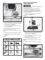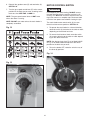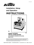
1
®
User Manual
Read and understand this manual before using machine.
INDUSTRIAL STOCK FEEDERS
Model Number
35660
®
C
US
Model Number
35655
STEEL CITY TOOL WORKS
VER. 10.06
Manual Part No. OR73267
®
l City Stock Feeder.
ee
St
w
ne
ur
yo
ng
si
ha
rc
THANK YOU for pu
, and inspected with you,
ed
st
te
,
ed
gn
si
de
en
be
s
This stock feeder ha
, used and mained
bl
m
se
as
ly
er
op
pr
n
he
the customer, in mind. W
with years of trouble free
u
yo
e
id
ov
pr
ill
w
er
ed
tained, your stock fe
longest machinery
e
th
of
e
on
by
ed
ck
ba
is
service, which is why it
ss.
warranties in the busine
in the Steel City’s
ts
uc
od
pr
y
an
m
of
e
on
This stock feeder is just
t
proof of our commitmen
is
d
an
ry
ne
hi
ac
m
ng
ki
family of woodwor
ction.
to total customer satisfa
cellence each and every
ex
r
fo
e
riv
st
to
ue
in
nt
At Steel City we co
. For comments
er
om
st
cu
r
ou
u,
yo
of
n
day and value the opinio
eb
Works, please visit our w
ol
To
ity
C
l
ee
St
or
er
ed
about your stock fe
works.com .
site at www.steelcitytool
2
TABLE OF CONTENTS
INTRODUCTION
SECTION 1
Warranty .................................................................................................................................................4
SECTION 2
Product Specifications ............................................................................................................................7
SECTION 3
Feature Identification ..............................................................................................................................8
SECTION 4
General Safety........................................................................................................................................9
SECTION 5
Product Safety ......................................................................................................................................11
SECTION 6
Electrical Requirements and Grounding Instructions ...........................................................................12
SECTION 7
Unpacking & Inventory..........................................................................................................................14
SECTION 8
Assembly ..............................................................................................................................................16
SECTION 9
Adjustments ..........................................................................................................................................19
SECTION 10
Operations ............................................................................................................................................22
SECTION 11
Maintenance .........................................................................................................................................24
SECTION 12
Parts List...............................................................................................................................................26
INTRODUCTION
This user manual is intended for use by anyone working with this machine. It should be kept available
for immediate reference so that all operations can be performed with maximum efficiency and safety.
Do not attempt to perform maintenance or operate this machine until you have read and understand the
information contained in this manual.
The drawings, illustrations, photographs, and specifications in this user manual represent your machine
at time of print. However, changes may be made to your machine or this manual at any time with no
obligation to Steel City Tool Works.
3
WARRANTY
1 YEAR LIMITED WARRANTY
Steel City Tool Works, LLC (SCTW) warrants this SCTW machinery to be free of defects in workmanship and materials for a period
of 1 years from the date of the original retail purchase by the original owner for domestic use. Granite components are warranted for
1 years based on normal use and is void if non SCTW accessories are used that cause the break or chip. Customer must advise
SCTW within 30 days for any damage or defect found upon receipt of the product to qualify for the warranty on granite.
The warranty does not cover any product used for professional or commercial production purpose nor for industrial or educational
applications. Such cases are covered by our 1 year Limited Warranty with the Conditions and Exceptions listed below.
Conditions and exception:
Warranty applies to the original buyer only and may not be transferred. Original proof of purchase is required.
Warranty does not include failures, breakage or defects deemed after inspection by an Authorized Service Center, (ASC) or agent of,
have been directly or indirectly caused by or resulting from improper use, lack of or improper maintenance, misuse or abuse,
negligence, accidents, damage in handling or transport, or normal wear and tear of any part or component.
Additionally, warranty is void if repairs or alterations are made to the machine by an unauthorized service center without the direct
consent of SCTW
Consumables such as blades, knives, bits and sandpaper are not covered.
Wear items such as drive belt, bearings, switch, are covered for 1 year.
To file a claim of warranty or to find a service center, call toll free 877-724-8665 or email [email protected] and
you must be able to present the original or photo copy of the sales receipt including the serial number from the machine and/or carton.
SCTW will inspect, repair or replace, at its expense and its option, any part that has proven to be defective in workmanship or
material, provided that the customer returns the product prepaid to a designated ASC and provides SCTW with a reasonable
opportunity to verify the alleged defect by inspection. SCTW will return the product or replacement at our expense unless it is
determined by us that there is no defect or that the defect resulted from causes not within the scope of our warranty in which case we
will, at your direction, dispose of or return the product. In the event you choose to have the product returned, you will be responsible
for the handling and shipping costs of the return.
SCTW furnishes the above warranties in lieu of all other warranties, express or implied. SCTW shall not be liable for any special,
indirect, incidental, punitive or consequential damages, including without limitation loss of profits arising from or related to the
warranty, the breach of any agreement or warranty, or the operation or use of its machinery, including without limitation damages
arising from damage to fixtures, tools, equipment, parts or materials, direct or indirect loss caused by and other part, loss of revenue
or profits, financing or interest charges, and claims by and third person, whether or not notice of such possible damages has been
given to SCTW. Damages or any kind for any delay by or failure of SCTW to perform its obligations under this agreement or claims
made a subject of a legal proceeding against SCTW more than one (1) year after such cause of action first arose.
The validity, construction and performance of this Warranty and any sale of machinery by SCTW shall be governed by the law of the
Commonwealth of Pennsylvania, without regard to conflicts of law’s provisions of any jurisdiction. Any action related in any way to
any alleged or actual offer, acceptance or sale by SCTW or any claim related to the performance of and agreement including without
limitation this Warranty, shall take place in the federal or state courts in Allegheny County, Pennsylvania.
Warranty registration card must be submitted to SCTW for purpose of proof within 90 days of purchase with a copy of the sales
receipt. Failure to do so will, revert the 1 year warranty to 1/2 year as in the terms stated above. This registration is also ne
eded to
facilitate contact in case of a safety recall.
This warranty gives you specific legal rights and you may have other rights which vary in certain States or Provinces.
Note to user
This instruction manual is meant to serve as a guide only. Specification and references are subject to change without prior notice.
Check the website www.steelcitytoolworks.com for updated manuals with reference to the VER# located on the front page.
LIMITED WARRANTY
The warranty does not cover any product used for professional or commercial production purpose nor for industrial or educational
applications. Such cases are covered by our 30 days Limited Warranty with the Conditions and Exceptions listed previously.
4
WARRANTY CARD
Name ________________________________________________
Street _______________________________________________
Apt. No. ______________________________________________
City _________________________ State ______ Zip __________
Phone Number_________________________________________
8.
How would you rank your woodworking skills?
___ Simple
___ Intermediate
___ Advance
___ Master Craftsman
9.
How many Steel City machines do you own? _______________
E-Mail ________________________________________________
10. What stationary woodworking tools do you own?
Check all that apply.
___ Air Compressor
___ Band Saw
Product Description:_____________________________________
Model No.: ___________________________________________
Serial No. _____________________________________________
The following information is given on a voluntary basis
and is strictly confidential.
1.
Where did you purchase your STEEL CITY machine?
Store: ____________________________________________
City:______________________________________________
2.
How did you first learn of Steel City Tool Works?
___ Advertisement
___ Mail Order Catalog
___ Web Site
___ Friend
___ Local Store
Other_______________________
CUT HERE
3.
4.
___ Fine Woodworking
___
___
___
___
___ Old House Journal
___ Popular Science
___ Today’s Homeowner
___ Woodcraft
Journal of Light Construction
Popular Mechanics
Popular Woodworking
WOOD
6.
___ Mortiser
___ Planer
___ Panel Saw
___ Power Feeder
11. Which benchtop tools do you own? Check all that apply.
___ Belt Sander
___ Belt / Disc Sander
___ Drill Press
___ Band Saw
___ Grinder
___ Mini Lathe
___ Spindle / Belt Sander
___ Mini Jointer
___ Scroll Saw
Other_____________________
12. Which portable / hand held power tools do you own?
Check all that apply.
___ Belt Sander
___ Biscuit Jointer
___ Dust Collector
___ Circular Saw
___ WOODEN Boat
___ Woodshop News
___ Detail Sander
___ Miter Saw
___ Drill / Driver
___ Orbital Sander
___ Woodsmith
___ Woodworker
___ Workbench
___ Woodwork
___ Woodworker’s Journal
Other_________________
___ Palm Sander
___ Saber Saw
___ Router
___ Portable Thickness Planer
___ Reciprocating Saw
Other______________________
13. What machines / accessories would you like to see added to the
STEEL CITY line?
Which of the following woodworking / remodeling shows do
you watch?
___ Backyard America
___ The American Woodworker
___ Home Time
___ This Old House
___ The New Yankee Workshop
___ Woodwright’s Shop
___________________________________________________
___________________________________________________
14. What new accessories would you like to see added?
Other__________________________________________
5.
___ Drum Sander
___ Horizontal Boring Machine
___ Lathe
___ Radial Arm Saw
___ Shaper
___ Spindle Sander
___ Table Saw
___ Vacuum Veneer Press
___ Wide Belt Sander
Other_______________________________________________
Which of the following magazines do you subscribe to?
___ American Woodworker
___ American How-To
––– Cabinetmaker
___ Family Handyman
___ Fine Homebuilding
___ Drill Press
___ Dust Collection
___ Jointer
___________________________________________________
___________________________________________________
What is your annual household income?
___ $20,000 to $29,999
___ $40,000 to $49,999
___ $30,000 to $39,999
___ $50,000 to $59,999
___ $60,000 to $69,999
___ $80,000 to $89,999
___ 70,000 to $79,999
___ $90,000 +
What is your age group?
___ 20 to 29 years
___ 40 to 49 years
___ 60 to 69 years
15. Do you think your purchase represents good value?
___Yes
___ No
16. Would you recommend STEEL CITY products to a friend?
___ Yes
___ No
___ 30 to 39 years
___ 50 to 59 years
___ 70 + years
17. Comments:
___________________________________________________
___________________________________________________
7.
___________________________________________________
___________________________________________________
How long have you been a woodworker?
___ 0 to 2 years
___ 2 to 8 years
___ 8 to 20 years
___ over 20 years
___________________________________________________
5
FOLD ON DOTTED LINE
PLACE
STAMP
HER E
SteelCityToolWorks
#4 Northpoint Court
Bolingbrook, IL 60440
FOLD ON DOTTED LINE
6
PRODUCT SPECIFICATIONS
MODEL 35655 (3-wheel)
MODEL 35660 (4-wheel)
MOTOR
MOTOR
Type
Induction TEFC
Type
Induction TEFC
Horsepower
1HP
Horsepower
1HP
Amps
4.2/2.5
Amps
4.2/2.5
Voltage
230V only
Voltage
230V only
Phase
single
Phase
single
Hertz
60
Hertz
60
RPM
3210-1700
RPM
3210-1700
PRODUCT DIMENSIONS
PRODUCTION DIMENSIONS
Height
29in.
Height
29in.
Length
(arm fully extended)
25in.
Length
(arm fully extended)
25in.
Net weight
141lbs
Net weight
152lbs
GENERAL
GENERAL
Number of rollers
3 (rubber)
Number of rollers
4 (rubber)
Number of speeds
4
Number of speeds
8
Speed ranges
(13,26,36,72Ft/min.)
(4,8,10,20M/min.)
Speed ranges
(6.5,13,18,22,36,43,
55,108Ft/min.)
Max height of rollers
parallel to table
8in.
Swing
360deg.
Forward and reversing
Yes
(2,4,5.5,6.7,11,13
16.5,33M/min.)
SHIPPING DIMENSIONS
Box 1
Max height of rollers
parallel to table
8in.
Swing
360deg.
Forward and reversing
Yes
Box 2
Length
21.5 in
Length
30 in.
Width
21.5 in.
Width
12 in.
Depth
11 in.
Depth
12 in.
Gross Weight
68 lbs.
Gross Weight
79 lbs.
SHIPPING DIMENSIONS
Box 1
7
Box 2
Length
29.5 in.
Length
30 in.
Width
22 in.
Width
12 in.
Depth
11 in.
Depth
12 in.
Gross Weight
79 lbs.
Gross Weight
79 lbs.
FEATURE IDENTIFICATION
Model 35660 Shown
4
5
6
3
2
7
9
8
1
1. Base
2. Handwheel (horizontal)
3. Horizontal Arm
4. Handwheel (vertical)
5. Motor
6. Switch
7. Elevating Bracket
8. Vertical Arm
9. Motor Clamp
8
GENERAL SAFETY
!
WARNING
!
WARNING
TO AVOID serious injury and damage to the machine,
read and follow all Safety and Operating Instructions
before assembling and operating this machine.
This manual is not totally comprehensive. It does not
and can not convey every possible safety and operational problem which may arise while using this
machine. The manual will cover many of the basic and
specific safety procedures needed in an industrial environment.
Exposure to the dust created by power sanding, sawing, grinding, drilling and other construction activities
may cause serious and permanent respiratory or
other injury, including silicosis (a serious lung disease), cancer, and death. Avoid breathing the dust,
and avoid prolonged contact with dust. The dust
may contain chemicals known to the State of
California to cause cancer, birth defects or other
reproductive harm.
All federal and state laws and any regulations having
jurisdiction covering the safety requirements for use of
this machine take precedence over the statements in
this manual. Users of this machine must adhere to all
such regulations.
Some examples of these chemicals are:
• Lead from lead-based paints.
• Crystalline silica from bricks, cement and other
masonry products.
• Arsenic and chromium from chemically-treated
lumber.
Below is a list of symbols that are used to attract your
attention to possible dangerous conditions.
!
This is the safety alert symbol. It is used to alert you to
potential personal injury hazards. Obey all safety messages that follow this symbol to avoid possible injury or
death.
!
Always operate tool in well ventilated area and provide for proper dust removal. Use a dust collection
system along with an air filtration system whenever
possible. Always use properly fitting NIOSH/OSHA
approved respiratory protection appropriate for the
dust exposure, and wash exposed areas with soap
and water.
DANGER
Indicates an imminently hazardous situation which, if
not avoided, WILL result in death or serious injury.
!
1. To avoid serious injury and damage to the machine,
read the entire User Manual before assembly and
operation of this machine.
WARNING
Indicates a potentially hazardous situation which, if not
avoided, COULD result in death or serious injury.
!
CAUTION
!
WARNING
Indicates a potentially hazardous situation, if not avoided, MAY result in minor or moderate injury. It may also
be used to alert against unsafe practices.
2. ALWAYS wear eye protection. Any machine can
throw debris into the eyes during operations,
which could cause severe and permanent eye
damage. Everyday eyeglasses are NOT safety
glasses. ALWAYS wear Safety Goggles (that
comply with ANSI standard Z87.1) when operating power tools.
CAUTION
CAUTION used without the safety alert symbol indicates a potentially hazardous situation which, if not
avoided, may result in property damage.
NOTICE
This symbol is used to alert the user to useful information about proper operation of the machine.
9
!
11. DO NOT FORCE the machine to perform an operation for which it was not designed. It will do a safer
and higher quality job by only performing operations
for which the machine was intended.
WARNING
12. DO NOT stand on a machine. Serious injury could
result if it tips over or you accidentally contact any
moving part.
3. ALWAYS wear hearing protection. Plain cotton is
not an acceptable protective device. Hearing
equipment should comply with ANSI S3.19
Standards.
!
13. DO NOT store anything above or near the machine.
14. DO NOT operate any machine or tool if under the
influence of drugs, alcohol, or medication.
WARNING
15. EACH AND EVERY time, check for damaged parts
prior to using any machine. Carefully check all
guards to see that they operate properly, are not
damaged, and perform their intended functions.
Check for alignment, binding or breakage of all
moving parts. Any guard or other part that is damaged should be immediately repaired or replaced.
4. ALWAYS wear a NIOSH/OSHA approved dust
mask to prevent inhaling dangerous dust or airborne particles.
16. Ground all machines. If any machine is supplied
with a 3-prong plug, it must be plugged into a 3contact electrical receptacle. The third prong is
used to ground the tool and provide protection
against accidental electric shock. DO NOT remove
the third prong.
5. ALWAYS keep the work area clean, well lit, and
organized. DO NOT work in an area that have slippery floor surfaces from debris, grease, and wax.
6. ALWAYS unplug the machine from the electrical
receptacle when making adjustments, changing
parts or performing any maintenance.
17. Keep visitors and children away from any machine.
DO NOT permit people to be in the immediate work
area, especially when the machine is operating.
7. AVOID ACCIDENTAL STARTING. Make sure that
the power switch is in the “OFF” position before
plugging in the power cord to the electrical
receptacle.
!
18. KEEP protective guards in place and in working
order.
19. MAINTAIN your balance. DO NOT extend yourself
over the tool. Wear oil resistant rubber soled shoes.
Keep floor clear of debris, grease, and wax.
WARNING
20. MAINTAIN all machines with care. ALWAYS KEEP
machine clean and in good working order. KEEP all
blades and tool bits sharp.
21. NEVER leave a machine running, unattended. Turn
the power switch to the OFF position. DO NOT
leave the machine until it has come to a complete
stop.
8. AVOID a dangerous working environment. DO
NOT use electrical tools in a damp environment
or expose them to rain or moisture.
!
22. REMOVE ALL MAINTENANCE TOOLS from the
immediate area prior to turning the machine ON.
WARNING
23. SECURE all work. When it is possible, use clamps
or jigs to secure the workpiece. This is safer than
attempting to hold the workpiece with your hands.
24. STAY ALERT, watch what you are doing, and use
common sense when operating any machine. DO
NOT operate any machine tool while tired or under
the influence of drugs, alcohol, or medication. A
moment of inattention while operating power tools
may result in serious personal injury.
9. CHILDPROOF THE WORKSHOP AREA by
removing switch keys, unplugging tools from the
electrical receptacles, and using padlocks.
10. DO NOT use electrical tools in the presence of
flammable liquids or gasses.
10
28. SAVE these instructions and refer to them frequently and use them to instruct other users.
25. USE ONLY recommended accessories. Use of
incorrect or improper accessories could cause serious injury to the operator and cause damage to the
machine. If in doubt, DO NOT use it.
29. Information regarding the safe and proper operation
of this tool is also available from the following
sources:
Power Tool Institute
1300 Summer Avenue
Cleveland, OH 44115-2851
www.powertoolinstitute.org
National Safety Council
1121 Spring Lake Drive
Itasca, IL 60143-3201
American National Standards Institute
25 West 43rd Street, 4th floor
New York, NY 10036
www.ansi.org
ANSI 01.1 Safety Requirements for
Woodworking Machines, and the U.S. Department
of Labor regulations
www.osha.gov
26. THE USE of extension cords is not recommended
for 230V equipment. It is better to arrange the
placement of your equipment and the installed
wiring to eliminate the need for an extension cord.
If an extension cord is necessary, refer to the chart
in the Grounding Instructions section to determine
the minimum gauge for the extension cord. The
extension cord must also contain a ground wire and
plug pin.
27. Wear proper clothing, DO NOT wear loose clothing,
gloves, neckties, or jewelry. These items can get
caught in the machine during operations and pull
the operator into the moving parts. Users must
wear a protective cover on their hair, if the hair is
long, to prevent it from contacting any moving parts.
PRODUCT SAFETY
6. Safety decals are on this machine to warn and
direct you to how to protect yourself or visitors from
personal injury. These decals MUST be maintained
so that they are legible. REPLACE decals that are
not legible.
1. Serious personal injury may occur if normal safety
precautions are overlooked or ignored. Accidents
are frequently caused by lack of familiarity or failure
to pay attention. Obtain advice from supervisor,
instructor, or another qualified individual who is
familiar with this machine and its operations.
7. DO NOT leave the unit plugged into the electrical
outlet. Unplug the unit from the outlet when not in
use and before servicing, performing maintenance
tasks, or cleaning.
2. Every work area is different. Always consider safety first, as it applies to your work area. Use this
machine with respect and caution. Failure to do so
could result in serious personal injury and damage
to the machine.
8. ALWAYS turn the power switch “OFF” before
unplugging the stock feeder.
3. Prevent electrical shock. Follow all electrical and
safety codes, including the National Electrical Code
(NEC) and the Occupational Safety and Health
Regulations (OSHA). All electrical connections and
wiring should be made by qualified personnel only.
!
!
WARNING
9. DO NOT handle the plug or stock feeder with
wet hands.
WARNING
10. USE accessories only recommended by Steel City.
11. DO NOT pull the machine by the power cord.
NEVER allow the power cord to come in contact
with sharp edges, hot surfaces, oil or grease.
4. TO REDUCE the risk of electrical shock. DO
NOT use this machine outdoors. DO NOT
expose to rain or moisture. Store indoors in a
dry area.
12. DO NOT unplug the stock feeder by pulling on the
power cord. ALWAYS grasp the plug, not the cord.
13. REPLACE a damaged cord immediately. DO NOT
use a damaged cord or plug. If the machine is not
operating properly, or has been damaged, left outdoors or has been in contact with water.
5. STOP using this machine, if at any time you experience difficulties in performing any operation.
Contact your supervisor, instructor or machine
service center immediately.
11
22. Cutting tools MUST be rotating before feeding.
14. DO NOT use the stock feeder as a toy. DO NOT
use near or around children.
23. DO NOT overload the cutting tool by feeding too
fast.
15. KEEP hands away from rollers.
24. ALWAYS keep hands away from rotating parts.
16. NEVER feed stock between the fence and the
cutter.
25. PROVIDE support for long stock on out-feed end of
table.
17. ALWAYS feed against the rotation of the cutter.
26. STOP the feeder before stopping the cutting tool.
18. ONLY use flat workpieces in the stock feeder, never
use warped or twisted lumber.
27. NEVER turn the feeder on with the work piece
contacting the stock feeder.
19. NEVER take off too much material in one pass.
Make several lighter passes.
28. ALLOW the blade of the cutting machine to come
to full speed BEFORE feeding a work piece into the
stock feeder.
20. USE guards, guides, and hold-down wherever
possible.
29. Turn the machine OFF and DISCONNECT POWER
before adjusting or changing set ups or when
making repairs.
21. ALWAYS use proper speed setting for the cutter
being used.
ELECTRICAL REQUIREMENTS
!
WARNING
The switch provided with your stock feeder is designed
for 230 volt single phase usage only. The switch has a
plug that is designed to plug into a 230 volt outlet.
There are many different configurations for 230 volt
outlets, so it is conceivable that the configuration of the
plug may not match the configuration of your existing
outlet. If this is the case, you will have to replace the
plug with a UL/CSA approved plug that matches the
configuration of your 230V outlet.
To reduce the risk of electric shock, follow all electrical and safety codes, including the National Electric
Code (NEC) and the Occupational Safety and Health
Regulations (OSHA). All electrical connections and
wiring should be made by qualified personnel only.
12
GROUNDING INSTRUCTIONS
!
The motor supplied with your machine is a 230 volt,
single phase motor. Never connect the green or ground
wire to a live terminal.
WARNING
A machine with a 230 volt plug should only be connected to an outlet having the same configuration as the
plug.
This machine MUST BE GROUNDED while in use to
protect the operator from electric shock.
EXTENSION CORDS
In the event of a malfunction or breakdown, GROUNDING provides the path of least resistance for electric
current and reduces the risk of electric shock. The plug
MUST be plugged into a matching electrical receptacle
that is properly installed and grounded in accordance
with ALL local codes and ordinances.
!
If a plug is provided with your machine DO NOT modify
the plug. If it will not fit your electrical receptacle, have
a qualified electrician install the proper connections to
meet all electrical codes local and state. All connections
must also adhere to all of OSHA mandates.
WARNING
To reduce the risk of fire or electrical shock, use the
proper gauge of extension cord. When using an
extension cord, be sure to use one heavy enough to
carry the current your machine will draw.
IMPROPER ELECTRICAL CONNECTION of the equipment-grounding conductor can result in risk of electric
shock. The conductor with the green insulation (with or
without yellow stripes) is the equipment-grounding conductor. DO NOT connect the equipment-grounding conductor to a live terminal if repair or replacement of the
electric cord or plug is necessary.
The smaller the gauge-number, the larger the diameter
of the extension cord is. If in doubt of the proper size of
an extension cord, use a shorter and thicker cord. An
undersized cord will cause a drop in line voltage resulting in a loss of power and overheating.
Check with a qualified electrician or service personnel if
you do not completely understand the grounding
instructions, or if you are not sure the tool is properly
grounded.
USE ONLY a 3-wire extension cord that has a 3-prong
grounding plug and a 3-pole receptacle that accepts the
machine’s plug.
!
If you are using an extension cord outdoors, be sure it
is marked with the suffix “W-A” (“W” in Canada) to indicate that it is acceptable for outdoor use.
PLUGS/RECEPTACLES
!
CAUTION
Make certain the extension cord is properly sized, and
in good electrical condition. Always replace a worn or
damaged extension cord immediately or have it
repaired by a qualified person before using it.
WARNING
Protect your extension cords from sharp objects, excessive heat, and damp or wet areas.
• Electrocution or fire could result if this machine is
not grounded properly or if the electrical configuration does not comply with local and state electrical
codes.
MINIMUM RECOMMENDED GAUGE FOR EXTENSION CORDS (AWG)
230 VOLT OPERATION ONLY
• MAKE CERTAIN the machine is disconnected
from power source before starting any electrical
work.
• MAKE SURE the circuit breaker does not exceed
the rating of the plug and receptacle.
13
25’ LONG
50’ LONG
100’ LONG
0 to 6 Amps
16 AWG
16 AWG
14 AWG
6 to 8 Amps
16 AWG
16 AWG
12 AWG
8 to 12 Amps
14 AWG
14 AWG
10 AWG
12 to 15 Amps
12 AWG
12 AWG
10 AWG
15 to 20 Amps
10 AWG
10 AWG
Not
recommended
UNPACKING & INVENTORY
!
After cleaning, apply a good quality paste wax to any
unpainted surfaces. Make sure to buff out the wax
before assembly.
WARNING
• The machine is heavy, two people are required to
unpack and lift.
Compare the items to inventory figures; verify that all
items are accounted for before discarding the shipping
box.
Check shipping carton and machine for damage before
unpackaging. Carefully remove packaging materials,
parts and machine from shipping carton. Always check
for and remove protective shipping materials around
motors and moving parts. Lay out all parts on a clean
work surface.
!
WARNING
If any parts are missing, do not attempt to plug in the
power cord and turn “ON” the machine. The machine
should only be turned “ON” after all the parts have been
obtained and installed correctly. For missing parts,
contact Steel City at 1-877-SC4-TOOL.
Remove any protective materials and coatings from all
of the parts and the stock feeder. The protective coatings can be removed by spraying WD-40 on them and
wiping it off with a soft cloth. This may need redone
several times before all of the protective coatings are
removed completely.
Model 35655
14
Model 35660
1. Handle
2. Base
3. Elevating Bracket
4
3
4. Horizontal Arm
8
5. Vertical Arm
6. Drilling Template
(not shown)
7. Grease gun
(not shown)
8. Motor Clamp
2
5
1
15
ASSEMBLY
!
ATTACHING THE
SUPPORT ASSEMBLY
WARNING
The stock feeder and auxiliary machine to which you
are mounting the stock feeder should be disconnected
from the power during installation.
!
WARNING
NOTE: Keep in mind the length of the horizontal arm
when mounting the stock feeder so you have room for
proper adjustment.
Make certain that both machines are disconnected
from the power source.
NOTE: DO NOT drill though any table ribs or table
supports.
1. Loosen locking lever (A). SEE FIG. 2.
2. Insert vertical arm (B) of support assembly into the
mounting bracket (C).
NOTE: Leave enough space around the work area for
loading and off-loading stock.
3. Tighten locking lever (A) on the mounting bracket to
hold the support assembly in place.
ATTACHING THE
TABLE MOUNTING BRACKET
!
Fig. 2
WARNING
Make certain that both machines are disconnected
from the power source.
1. Determine the location for the mounting bracket on
the table.
2. Clean the mounting surface and apply the supplied
drilling template in the location selected.
B
3. Center punch and drill four 3/8” diameter holes.
Remove drilling template.
NOTE: DO NOT drill though any table ribs or table
supports.
4. Secure the mounting bracket to the table with four
2” bolts, four flat washers and four hex nuts (not
provided) through the four holes in the mounting
bracket. SEE FIG. 1.
Fig. 1
A
16
C
4. Thread the handle (D) into the handwheel with the
supplied 3-1/2” screw and nut. SEE FIG. 3.
Fig. 4-1
5. Loosen locking lever (E).
6. Insert the horizontal arm (G) into elevating
bracket (F).
NOTE: The gear rack of the horizontal arm must be on
the bottom. The horizontal arm must be started with the
end that has the gear rack extending all the way to the
end.
7. Tighten locking handle (E).
B
Fig. 3
A
D
E
2. Rotate the motor assembly clockwise until the
switch (C) is on the same side of the stock feeder
as the gear cover (D). SEE FIG.4-2.
Fig. 4-2
G
C
F
D
REPOSITIONING
THE MOTOR ASSEMBLY
!
WARNING
Make certain that both machines are disconnected
from the power source.
1. Loosen and remove the four bolts and four lock
washers (A), (only two are shown) on the motor
collar (B). SEE FIG.4-1.
3. Align the four holes in the motor collar (B) with the
four threaded holes in the feeder base. Reinstall
and tighten the four bolts and four lock washers
removed in Step 1. SEE FIG. 4-1.
17
ATTACHING
THE MOTOR CLAMP
!
ATTACHING THE STOCK FEEDER
TO THE SUPPORT ASSEMBLY
WARNING
!
WARNING
Make certain that both machines are disconnected
from the power source.
Make certain that both machines are disconnected
from the power source.
1. Place the motor clamp (C) around the motor collar.
SEE FIG. 4-3.
1. Loosen two bolts (B) on the arm bracket (A).
SEE FIG. 4-4.
2. Install the locking lever (A) and the bolt (B) into the
motor clamp (C).
2. Place the arm bracket (A) over the horizontal arm
as far as it will go and tighten the two bolts (B).
Fig. 4-3
Fig. 4-4
A
B
A
B
NOTE: The arm bracket goes over the end of the
horizontal arm where there is no gear rack.
C
3. Tighten the locking lever (A) and the bolt (B),
keeping the gap on both sides of the collar (C)
equal.
18
ADJUSTMENTS
Fig. 6
BASIC FEEDER AND SUPPORT
ASSEMBLY MOVEMENTS
!
WARNING
N
Make certain that both machines are disconnected
from the power source.
L
K
1. To rotate the entire stock feeder assembly, loosen
locking lever (A) on the base and swing the
assembly into the desired position. SEE FIG. 5.
2. To raise or lower the stock feeder, (G) loosen the
locking lever (C) and rotate the handwheel (D),
clockwise to raise and counter clockwise to lower.
M
3. To move the stock feeder (G) in or out, loosen
locking lever (E) and rotate the handwheel (B),
clockwise to extend and counter clockwise to
retract.
NOTE: The locking lever is spring loaded and can be
repositioned by pulling out on the handle and repositioning it on the nut located underneath the handle.
4. To adjust the position of the stock feeder (G)
parallel with the table, loosen locking lever (H) and
manually move the feeder into the desired position.
Retighten locking lever (H) after adjustments are
made.
7. Tighten all locking levers after adjustments are
complete.
FEED RATE ADJUSTMENTS
MODEL 35655 ONLY
NOTE: It may be necessary to loosen the two bolts (N)
on the arm bracket for proper alignment. Make sure to
retighten bolts after adjustment is made. SEE FIG. 6.
5. To adjust the stock feeder (G) in relation to the
fence, loosen locking lever (F) and manually move
the feeder into position. Retighten locking lever (F)
after adjustments are made. SEE FIG. 5.
!
WARNING
Make certain that both machines are disconnected
from the power source.
The 35655 Stock Feeder has 4 speeds available –
(13, 26, 33, 66 Ft/min.) - (4, 8, 10, 20 M/min.) –
depending on gear arrangement and motor switch
position.
Fig. 5
D
F
E
1. Unscrew the two knobs (A) and remove the gearbox cover (B). SEE FIG. 7.
C
Fig. 7
B
B
H
J
A
G
6. To rotate the stock feeder (L), loosen the locking
lever (K) on the motor clamp (M) and manually
move the feeder into the desired position. Retighten
the locking lever after adjustments are made.
SEE FIG. 6.
A
19
Fig. 8
FEED RATE ADJUSTMENTS
MODEL 35660 ONLY
!
WARNING
Make certain that both machines are disconnected
from the power source.
The 35660 Stock Feeder has 8 speeds available –
(6.5,13,18,22,36,43,55,108Ft/min.); (2,4,5.5,6.7,11,
13,16.5,33M/min.) depending on the configuration of
the gears, the position of the gear speed control lever,
and motor switch position.
D
1. Unscrew the two knobs (A) and remove the gearbox cover (B). SEE FIG. 10.
Fig. 10
C
2. Refer to the speed chart in Fig. 9 to select the feed
rate you want. This chart also appears on the inside
of the gearbox cover. SEE FIG. 9.
B
3. To change the gears (C), remove the hex nuts and
washers (D). SEE FIG. 8.
4. Remove the gears (C) from the shafts and reposition as shown on the feed rate chart.
A
NOTE: Make sure the keyway on the gears and shafts
line up.
2. Refer to the speed chart in Fig. 12 to select the feed
rate you want. This chart also appears on the inside
of the gearbox cover. SEE FIG. 12.
5. Reinstall the hex nuts and washers (D) and tighten.
6. Reinstall the gearbox cover (B) and two knobs (A).
SEE FIG. 7.
3. To change the gears (C), remove the hex nuts and
washers (D). SEE FIG. 11.
Fig. 9
4. Remove the gears (C) from the shafts and reposition as shown on the feed rate chart.
NOTE: Make sure the keyway on the gears and shaft
line up.
5. Reinstall the hex nuts and washers (D) and tighten.
Fig. 11
D
C
20
6. Reinstall the gearbox cover (B) and two knobs (A).
SEE FIG. 10.
MOTOR CONTROL SWITCH
!
7. Turn the gear speed control lever (E) to the correct
position for the feed rate you want according to the
feed rate chart. SEE FIGS. 12 AND 13.
WARNING
If a workpiece jams while feeding, DO NOT reverse
the feed direction while the auxiliary machine is still
running. Turn OFF both machines and wait till the cutting blade comes to a complete stop. Disconnect both
machines from power source before clearing the jam.
NOTE: The gear speed control lever will NOT move
unless the motor is running.
NOTE: DO NOT start motor unless the stock feeder is
completely assembled.
The stock feeder motor control switch (A) has two
forward and two reverse positions. SEE FIG. 14.
Fig. 12
1. To operate the stock feeder in a forward direction,
rotate the switch (A) clockwise to the turtle or rabbit
depending on the desired feed rate.
2. To reverse the direction of feed, rotate the switch
(A) counter clockwise to the turtle or rabbit depending on the desired feed rate.
NOTE: See the feed rate chart Fig. 9 for Model 35655
or Fig. 12 for Model 35660 to help select the switch
position for the feed rate you want.
3. To turn the feeder OFF, rotate the switch to any of
the three (0) positions.
Fig. 14
A
Fig. 13
E
21
OPERATIONS
This section covers basic stock feeder setup. It does
not and cannot convey every possible safety and
operational problem that may arise while using this
machine. Always follow all warning and operating
instructions for the machine that the stock feeder is
being attached to.
!
STOCK FEEDER ON A JOINTER
Position the stock feeder assembly on the Jointer so
that all of the rollers are over the outfeed table. The first
roller should be approximately 1/4” from the leading
edge of the outfeed table. The outfeed roller should be
approximately 1/4” closer to the fence than the infeed
roller. SEE FIG. 16.
WARNING
When used properly a stock feeder reduces the chance
of a kick back, however it is still possible. NEVER stand
directly behind the workpiece while feeding stock.
Fig. 16
Stock Feeder on Jointer
NOTE: If your stock feeder only has three rollers,
disregard the fourth dotted line roller.
STOCK FEEDER ON A TABLE SAW
Position the stock feeder assembly on the table saw so
that the center of the saw blade is between the infeed
roller and the middle roller. The outfeed roller should be
approximately 1/4” closer to the fence than the infeed
roller. SEE FIG. 15.
NOTE: Make certain the saw blade is no higher than
1/8 inch above the workpiece. Avoid contact with the
stock feeder rollers.
Fig. 15
Stock Feeder on Table Saw
Front of Table
22
STOCK FEEDER ON A SHAPER
STOCK FEEDER HEIGHT
ADJUSTMENT
Position the stock feeder assembly so that the cutter
head is between the first and middle rollers. The outfeed roller should be approximately 1/4” closer to the
fence than the infeed roller. SEE FIG.17.
Position the stock feeder height so that the distance
between the table and the feed rollers is approximately
1/8” less than the thickness of the work piece.
SEE FIG. 18.
Fig. 17
Fig. 18
Stock Feeder on Shaper
Stock Feeder Height Adjustment
STOCK FEEDER ROLLER
ALIGNMENT
Position the stock feeder so that all of the rollers make
contact with and set squarely on the work piece. SEE
FIG. 19.
Fig. 19
Wrong
Correct
Wrong
Wrong
Correct
23
Wrong
MAINTENANCE
LUBRICATION
! WARNING
GEARS AND CHAINS
Periodically lubricate the gears and chains (See Fig. 7
and 8 for Model 35655 or Fig. 10 and 11 for Model
35660) with a #2 grease or equivalent.
Make certain that both machines are disconnected
from the power source.
Fig. 20
CHANGING THE ROLLERS
!
WARNING
Make certain that both machines are disconnected
from the power source.
B
To remove a roller, loosen and remove the four cap
head screws (C) from the hub of the roller. Pull the
roller from the shaft. Installation is the reverse.
SEE FIG. 20.
C
NOTE: Rotating the roller positions periodically will
prolong the life of the rollers.
A
C
CLEANING
!
ROLLERS
Every 200 working hours, or 30 days the stock feeders
rollers should be greased using a # 2 grease or equivalent. Each roller has a grease fitting in the center of the
hub (A). SEE FIG. 20.
WARNING
Make certain that both machines are disconnected
from the power source.
!
WARNING
GEARBOX
After the first 200 working hours, or 30 days, the gearbox oil should be changed. After the initial oil change,
change every 1000 working hours, or 6 months with a
good quality gear oil.
With the stock feeder unplugged, blow off the motor
with low-pressure air to remove dust or dirt. Air
pressure above 50 P.S.I. should not be used, as
high-pressure air may damage insulation. The operator should always wear eye protection when using
compressed air.
To change oil:
1. Remove oil cap (B). SEE FIG. 20.
2. Turn the stock feeder body upside down, and
completely drain all oil into a catch pan.
!
3. Turn the stock feeder right side up and level.
CAUTION
Do not use flammable materials to clean the stock
feeder.
4. Model 35655 (3 wheel): Using new oil, add 300cc
or 10 oz. of oil.
Model 35660 (4 wheel): Using new oil, add 380cc
or 12.5 oz. of oil.
After cleaning, apply a good quality paste wax to all
unpainted surfaces.
NOTE: The oil level should be about 2" from the rim.
5. Reinstall the oil cap (B).
24
N NOTES N
25
PARTS
Model 35655 (3 wheel)
26
KEY
NO.
PART
NO.
DESCRIPTION
QTY.
KEY
NO.
PART
NO.
DESCRIPTION
100
OR73062
101
OR73202
Bearing
1
142
OR73116
Chain (40S)
Sprocket Case Assy, Const of: Ref 102 thru 105
1
143
OR73221
Worm Gear Assy, Const of: Ref 144 thru 149
102
1
OR73140
Grease Nipple
1
144
OR73080
Worm Gear 38T
1
103
OR73075
Sprocket Case
1
145
OR90304
Flat Washer M12
1
104
OR73127
Spring
1
146
OR90280
Hex Nut M12
1
QTY.
1
105
OR73148
Case Cap
1
147
OR73095
Wormgear Shaft
1
106
OR73204
Sprocket Case Assy, Const of: Ref 107 thru 110
2
148
OR73118
Key
1
107
OR73140
Grease Nipple
2
149
OR73120
Snap Ring
1
108
OR73075
Sprocket Case
2
150
OR73219
109
OR73127
Spring
2
Wormgear Box Cover Assy, Const of:
Ref 151 thru 154
1
151
OR73134
O-Ring
1
152
OR73078
Wormgear Box Cover
1
153
OR73135
Oil Seal
1
154
OR93955
Cap Screw M5x16
4
155
OR73223
Gear (25T/40T) Assy, Const of: Ref 156 thru 159
1
156
OR73048
Gear (25T)
1
157
OR73049
Gear (40T)
1
158
OR73133
O-Ring
1
159
OR73141
Grease Gun
1
160
OR73161
Motor Assy, Const of: Ref 161,162
1
161
OR72906
Spec. Plate
1
162
OR73158
Switch Assy, Const of: Ref 163 thru 175
1
163
OR73256
Switch (Not Shown)
1
110
OR73148
Case Cap
2
111
OR73206
Roller Support Assy, Const of: Ref 112 thru 116
3
112
OR73076
Roller Support
3
113
OR73047
Sprocket
3
114
OR91758
Cap Screw M6x16
6
115
OR92923
Cap Screw M8x40
6
116
OR73114
Chain (26S)
3
117
OR73208
Tube Assy, Const of: Ref 118,119
3
118
OR73081
Tube
3
119
OR73121
Snap Ring
3
120
OR73210
Sprocket Shaft Assy, Const of: Ref 121,122
2
121
OR73094
Sprocket Shaft
2
122
OR73119
Snap Ring
2
123
OR73212
Main Sprocket Shaft Assy, Const of:
Ref 124 thru 126
164
OR73257
Switch Box (Not Shown)
1
1
165
OR73258
Capacitor (Not Shown)
1
124
OR73101
Main Sprocket Shaft
1
166
OR73259
Switch Mounting Support (Not Shown)
1
125
OR90304
Flat Washer M12
1
167
OR73260
Forward/Reverse Label (Not Shown)
1
126
OR90280
Hex Nut M12
1
170
OR73261
Special Pan Head Screw (Not Shown)
1
127
OR73214
Roller Spindle Assy, Const of: Ref 128 thru 130
3
171
OR73262
Switch Knob (Not Shown)
1
128
OR73140
Grease Nipple
3
172
OR73263
129
OR73100
Roller Spindle Assy, Const of: Ref 129A,129B,129C
3
Pan Head Self-Tapping Screw 3.8mm x 22mm
(Not Shown)
4
173
OR73264
Power Cord (Not Shown)
1
174
OR73265
Cord Grommet (Not Shown)
1
175
OR73266
Warning Label (Not Shown)
1
176
OR73229
Gearbox Cap Assy, Const of: Ref 177 thru 179
1
177
OR73131
O-Ring
1
178
OR73145
Gearbox Cap
1
179
OR90877
Cap Screw M5x12
2
180
OR73151
Housing Cover, Incl: Ref 181,182,183
1
181
OR73246
Nameplate
1
129A
129B
129C
OR73253
OR73254
OR73255
Special Hex Bolt
Shaft
Retaining Ring
3
3
3
130
OR93912
Lock Washer M12
3
131
OR73217
Oil-Cap Assy, Const of: Ref 132,133
1
132
133
134
OR73143
OR73130
OR73163
Oil Cap
O-Ring
Housing Frame Assy, Const of: Ref 135 thru 137
1
1
1
135
OR73063
Housing Frame
1
135A
OR73245
Lubrication Label
1
136
OR73040
Bushing
1
137
OR90222
Set Screw M6x10
3
138
OR73165
Transmission Assy, Const of: Ref 139 thru 142
1
139
OR73042
Sprocket 12T
2
140
OR73117
Chain (62S)
1
141
OR73045
Double-Sprocket 12T
2
27
182
OR73247
Rivet
2
183
OR73248
Warning
1
184
OR73147
Knob
2
185
OR73138
Roller Assy, Const of: Ref 186 thru 188
3
186
OR73157
Tire
3
187
OR73079
Inner and Outer Wheel
3
188
OR93381
Cap Screw M8x20
6
Model 35660 (4 wheel)
28
KEY
NO.
PART
NO.
DESCRIPTION
QTY.
KEY
NO.
PART
NO.
DESCRIPTION
200
OR73062
201
OR73203
Bearing
1
251
OR73051
Gear 34T
1
Sprocket Case Assy, Const of: Ref 202 thru 205
2
252
OR73052
Gear 20T
202
1
OR73140
Grease Nipple
2
253
OR73103
Transmission Shaft
1
203
OR73075
Sprocket Case
2
254
OR90304
Flat Washer M12
1
204
OR73127
Spring
2
255
OR90280
Hex Nut M12
1
205
OR73148
Case Cap
2
256
OR73220
206
OR73205
Sprocket Case Assy, Const of: Ref 207 thru 210
2
Wormgear Box Cover Assy, Const of:
Ref 257 thru 260
1
257
OR73134
O-Ring
1
258
OR73078
Wormgear Box Cover
1
259
OR73135
Oil Seal
1
260
OR93955
Cap Screw M5x16
4
261
OR73168
Speed Lever Assy, Const of: Ref 262 thru 269
1
262
OR73096
Gear Lever
1
263
OR73122
Lock Pin
1
264
OR73129
O-Ring
1
265
OR73137
Steel Ball
1
266
OR73126
Comp. Spring
1
267
OR73146
Speed Lever
1
268
OR90145
Lock Washer M5
1
269
OR90877
Cap Screw M5x12
1
270
OR73169
Speed Lever Socket Assy, Const of:
Ref 271 thru 273
1
271
OR73131
O-Ring
1
272
OR73055
Speed Lever Socket
1
273
OR90877
Cap Screw M5x12
2
274
OR73224
Gear 25T/40T Assy, Const of: Ref 275,276
1
275
OR73048
Gear 25T
1
276
OR73049
Gear 40T
1
277
OR73133
O-Ring
1
278
OR73141
Grease Gun
1
279
OR73161
Motor Assy, Const of: Ref 280,281
1
4
280
OR72905
Spec. Plate
1
207
OR73140
Grease Nipple
2
208
OR73075
Sprocket Case
2
209
OR73127
Spring
2
210
OR73148
Case Cap
2
211
OR73207
Roller Support Assy, Const of: Ref 212 thru 216
4
212
OR73076
Roller Support
4
213
OR73047
Sprocket
4
214
215
OR91758
OR92923
Cap Screw M6x16
Cap Screw M8x40
8
8
216
OR73114
Chain (26S)
4
217
OR73209
Tube Assy, Const of: Ref 218,219
4
218
219
OR73081
OR73121
Tube
Snap Ring
4
4
220
OR73211
Sprocket Shaft Assy, Const of: Ref 221,222
3
221
OR73094
Sprocket Shaft
3
222
OR73119
Snap Ring
3
223
OR73213
Main Sprocket Shaft Assy, Const of:
Ref 224 thru 226
224
OR73101
Main Sprocket Shaft
1
1
225
OR90304
Flat Washer M12
1
226
OR90280
Hex Nut M12
1
227
OR73215
Roller Spindle Assy, Const of: Ref 228 thru 230
4
228
OR73140
Grease Nipple
4
229
OR73100
Roller Spindle Assy, Const of:
Ref 229A,229B,229C
QTY.
229A
OR73253
Special Hex Bolt
4
281
OR73158
Switch Assy, Const of: Ref 282 thru 294
1
229B
OR73254
Shaft
4
282
OR73256
Switch (Not Shown)
1
229C
OR73255
Retaining Ring
4
283
OR73257
Switch Box (Not Shown)
1
230
OR93912
Lock Washer M12
4
284
OR73258
Capacitor (Not Shown)
1
231
OR73218
Oil-Cap Assy, Const of: Ref 232,233
1
285
OR73259
Switch Mounting Support (Not Shown)
1
232
OR73143
Oil Cap
1
286
OR73260
Forward/Reverse Label (Not Shown)
1
233
OR73130
O-Ring
1
289
OR73261
Special Pan Head Screw (Not Shown)
1
234
OR73164
Housing Frame Assy, Const of: Ref 235 thru 237
1
290
OR73262
Switch Knob (Not Shown)
1
291
OR73263
Pan Head Self-Tapping Screw 3.8mm x 22mm
(Not Shown)
4
292
OR73264
Power Cord (Not Shown)
1
293
OR73265
Cord Grommet (Not Shown)
1
235
OR73064
Housing Frame
1
235A
OR73245
Lubrication Label
1
236
OR73040
Bushing
1
237
OR90222
Set Screw M6x10
4
238
OR73166
Transmission Assy, Const of: Ref 239 thru 242
1
239
OR73042
Sprocket 12T
2
240
OR73116
Chain (40S)
2
241
OR73045
Double-Sprocket 12T
4
242
OR73117
Chain (62S)
1
243
OR73171
Worm Gear Assy, Const of: Ref 244 thru 247
1
244
OR73056
Gear 31T
1
245
OR73039
Worm Gear 38T
1
246
OR73057
Gear 17T
1
247
248
OR73040
OR73167
Bushing
Clutch Spindle Assy, Const of: Ref 249 thru 255
1
1
249
OR73043
Bushing
1
250
OR73050
Clutch
1
29
294
OR73266
Warning Label (Not Shown)
1
295
OR73230
Gearbox Cap Assy, Const of: Ref 296 thru 298
1
296
OR73131
O-Ring
1
297
OR73145
Gearbox Cap
1
298
OR90877
Cap Screw M5x12
2
1
299
OR73152
Housing Cover, Incl: Ref 300 thru 302
300
OR73246
Nameplate
1
301
OR73247
Rivet
2
302
OR73248
Warning
1
303
OR73147
Knob
2
304
OR73138
Roller Assy, Const of: Ref 305 thru 307
4
305
OR73157
Tire
4
306
OR73079
Inner and Outer Wheel
4
307
OR93381
Cap Screw M8x20
8
30
KEY
NO.
PART
NO.
DESCRIPTION
QTY.
KEY
NO.
PART
NO.
DESCRIPTION
300
OR73182
301
OR73082
Vertical Column Assy, Const of: Ref 301 thru 304
1
328
OR94331
Hex Screw M10x50
Vertical Column
1
329
OR73191
Swivel Cone Assy, Const of: Ref 330 thru 334
302
1
OR73108
Rack
1
330
OR73030
Swivel Cone
1
303
OR94279
Cap Screw M5x10
2
331
OR73086
Stud
1
304
OR93955
Cap Screw M5x16
1
332
OR73088
Lever
1
305
OR73183
Overarm Assy, Const of: Ref 306 thru 308
1
333
OR73124
Lock Pin
1
306
OR73083
Overarm
1
334
OR73104
Elevating Screw
1
307
OR73109
Rack
1
335
OR73194
Column Cap Assy, Const of: Ref 336, 337
1
308
OR94279
Cap Screw M5x10
4
336
OR73070
Column Cap
1
309
OR73185
Elevating Bracket Assy, Const of: Ref 310 thru 313
1
337
OR93913
Set Screw M8x12
3
310
OR73037
Elevating Bracket
1
338
OR73195
Handwheel Assy, Const of: Ref 339,340
1
311
OR73087
Lever
2
339
OR73155
Handwheel, Elevating
1
QTY.
2
312
OR73107
Stud
2
340
OR73125
Lock Pin
1
313
OR90304
Flat Washer M12
2
341
OR73144
Wheel-Handle
1
314
OR73186
Handwheel Assy, Const of: Ref 315,316
1
342
OR73199
Base Assy, Const of: Ref 343 thru 346
1
315
OR73153
Handwheel, Extension
1
343
OR73036
Column Base
1
316
OR73125
Lock Pin
1
344
OR73089
Lever
1
317
OR73188
Pinion Assy, Const of: Ref 318 thru 321
1
345
OR73107
Stud
1
318
OR73085
Pinion
1
346
OR90304
Flat Washer M12
1
319
OR94218
Set Screw M8x25
1
347
OR73200
Motor Clamp Assy, Const of: Ref 348 thru 350
1
320
OR90248
Lock Washer M8
1
348
OR73031
Motor Clamp
1
321
OR90307
Hex Nut M8
1
349
OR91497
Hex Bolt M8x50
1
322
OR73190
Overarm Cone Assy, Const of: Ref 323 thru 328
1
350
OR73139
Lever
1
323
OR73038
Overarm Cone
1
351
OR73249
Mounting Template (Not Shown)
1
324
OR73086
Stud
1
360
OR73267
Owner’s Manual English
1
325
OR73088
Lever
1
361
OR73269
Owner’s Manual Spanish
1
326
OR90227
Lock Washer M10
2
362
OR73268
Owner’s Manual French
1
327
OR73124
Lock Pin
1
31
DATE
MAINTENANCE PERFORMED
REPLACEMENT COMPONENTS REQUIRED
®
STEEL CITY
TOOL WORKS
www.steelcitytoolworks.com
1-877-SC4-TOOL
(1-877-724-8665)
NOTES
www.steelcitytoolworks.com
Steel City Tool Works, LLC Bolingbrook, IL. USA 60440
Tech Service: 1.877.724.8665